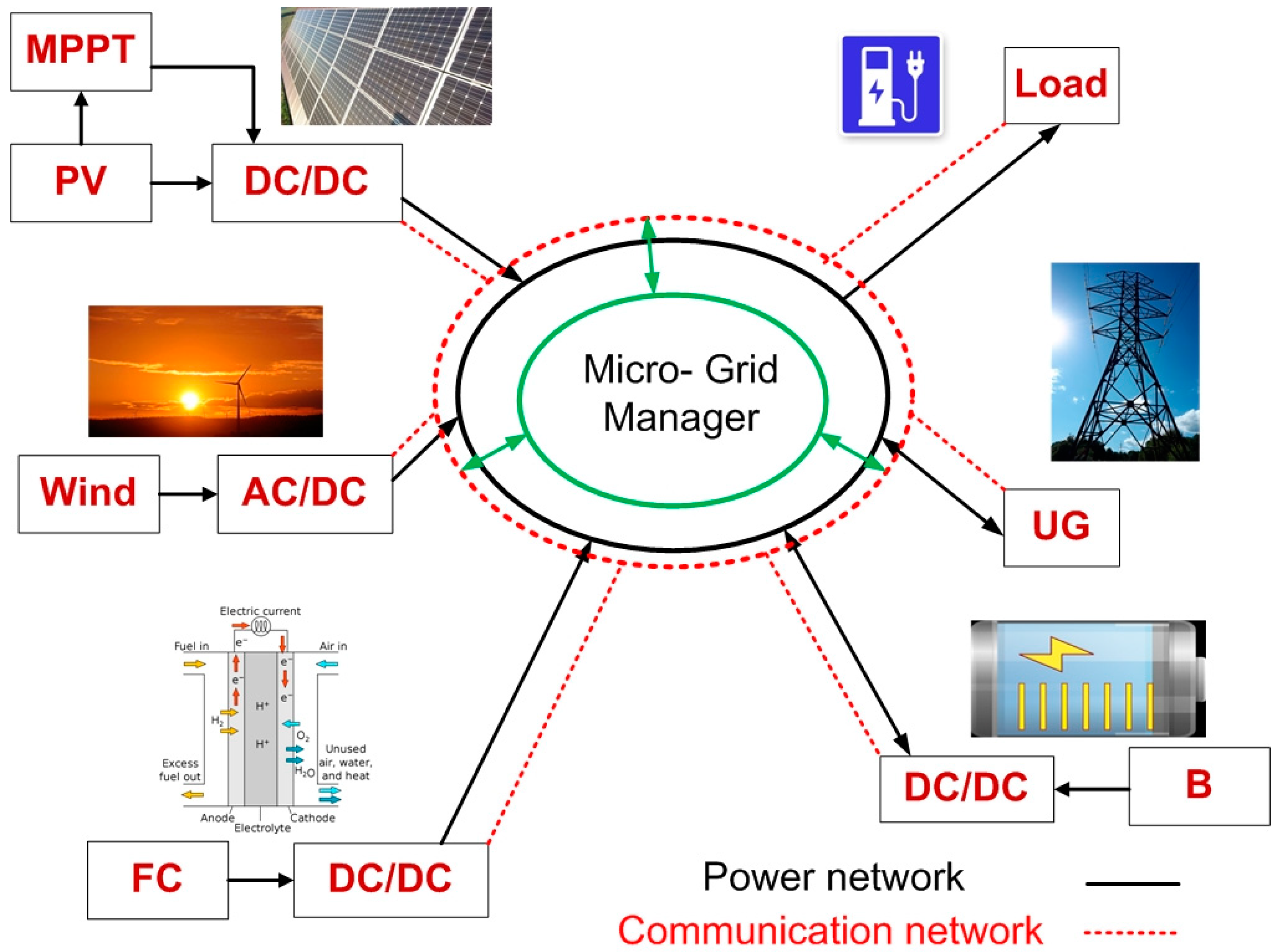
In power system grids, the microgrid is identified as a distributed energy system (DES), including generators, energy storage elements like batteries (B) and supercapacitors to balance the generated power and the consumed power [
1,
2,
3], an energy management system to control the entire operation of the microgrid sources [
4,
5], and load. All of these items are combined together and work in parallel with the utility grid, or out of grid as a stand-alone system used for a small area and few consumers [
6,
7]. Generally, the microgrid is considered a cluster of the utility grid [
8], as shown in
Figure 1. Using a utility grid for power distribution has some disadvantages, such as transmission losses, especially when the generating plants are far away from the consumers, bad environmental impact because of emission, and climate change due to the use of conventional resources in the generation phase. Microgrids represent an alternative option that has the potential to overcome these problems. Microgrids can minimize power losses through transmission, reduce CO
2 emissions, and limit climate change, especially when using renewable energy resources in electricity generation. It also saves money in several ways, such as preventing outage, selling electricity to national grids through feed, and tariff or net metering systems. Using power systems that combine renewable sources with zero emission besides energy storage elements makes the system able to achieve maximum efficiency compared to systems containing conventional sources [
9,
10,
11]. An energy management system is a system that controls the operation of the microgrid (MG) system. It uses many approaches and control strategies to get maximum system performance. These control strategies may include a state machine, a classic proportional–integral (PI) control, a fuzzy logic control, an external energy maximization, an equivalent minimization, and a frequency decoupling control strategy [
12].
Manoj et al. [
13] discussed the two main types of MG: Alternative current microgrid (ACMG) and direct current microgrid (DCMG). The DCMG has some advantages over the ACMG, such as high efficiency, easy connection on the DC bus, and system reliabilities. They confirmed that in DCMGs, there are three factors influencing power disturbance: Fluctuation of power exchange, power variation between the storage system and the power sources, and the fast change in the DC bus load. Ravichandrudu et al. [
14] designed an MG system using renewable sources, which has the benefits of utilizing renewable energy sources and reducing transmission losses when using wind and hydro. The proposed microgrid system has three operation modes. Phurailatpam et al. [
15] proposed a DCMG system that includes a photovoltaic (PV) power system and uses the battery as an energy storage system. The DC/DC converters were discussed, as well as the maximum power point tracking (MPPT) for the PV. The system performance at constant and variable values for irradiance, wind speed, and load was monitored and analyzed. The simulation results showed that the system maintained the DC bus voltage at constant value, which confirmed the advantages of the DCMG compared with the ACMG. Elsied et al. [
16] proposed a novel energy management strategy based on binary particle swarm optimization (BPSO) to optimize the performance of the MG, maximize the micro grid power, and decrease the system CO
2 emissions. The system was supported by an experimental lab test. The obtained results proved that the BPSO is efficient when used with the MG. For a DCMG hybrid system, Garita et al. [
17] examined the efficiency of an energy management strategy (EMS) used in a DCMG configuration containing a PV and a battery integrated together in one unit. An energy management system was used with three main system configurations. It works through seven operation modes as power flow direction under two different case studies (OFF—grid and peak shaving) to achieve maximum system performance. In their study of DCMG, Eghtedarpour et al. [
18] propose three levels of control to improve the performance of the DCMG. The first level is where no communication is required and the control is done based on the local measurements. The second level is based on a DC microgrid energy management system. The third level is the top level of control, which controls multi-microgrids. Shehata et al. [
19] proposed an energy management strategy for DCMG based on a multi-agent system applied using the JADE framework, where PI controllers are used as an EMS. The interface between the multi-agent system and the MATLAB/Simulink software was done through the MACSimJX interface. An analytical solution used as a reference model supported by a numerical method was proposed by Hadj-Said et al. [
20] to confirm the suitability of the proposed EMS used in parallel hybrid electric vehicles (HEV) to achieve maximum system performance. The proposed EMS was applied successfully on continuous and discrete optimization cases. Sedaghati et al. [
21] discussed a PV–FC–B–SC hybrid system based on grid-connected microgrids. A control strategy called adaptive fractional fuzzy sliding mode control (AFFSMC) was used for the inverter. The fuzzy rules are designed to accurately estimate the uncertain parameters. The results showed that the proposed strategy works efficiently. When the analytical solution was applied for a certain model, such as the optimal auxiliary functions method (OAFM) proposed by Herisanu et al. [
22], it was found to be a reliable and efficient tool for mechanical and electrical performance of the system. For the PV/wind hybrid system in a microgrid, the wind turbine generator is characterized by its slow response, while the PV array enjoys a fast response. If both generators are combined in one system, the voltage of the DC bus takes a long time to reach a stable condition that affects the overall system response, especially when the load is variably switching [
23]. For the battery/supercapacitor hybrid system, as proposed by Vasily et al. [
24], a number of the internal problems of the battery negatively affects the system’s overall performance, such as its short life cycle and its low efficiency due to the number of charging/discharging times, causing fast breakdown of the battery. For the PV/FC hybrid power system, the main problem is the efficiency of both the PV and the FC, and the low density and high initial cost of the PV arrays. Despite the concerns raised for the mentioned hybrid systems, sometimes the configuration itself cannot achieve its target, as [
25], when all the system components are connected in a series and, as a result, if there is a problem in any component (PV, Electrolyzer, storage, and FC), the power production could be affected, thus impacting the system’s financial return and cost. Using the PV as a preliminary source decreases the unwanted side effects of using the FC, such as low efficiency during the operation period, high cost, unstable low generated voltage, and finally, the high ripple current linked to the output voltage which reduces the FC lifetime [
26,
27].
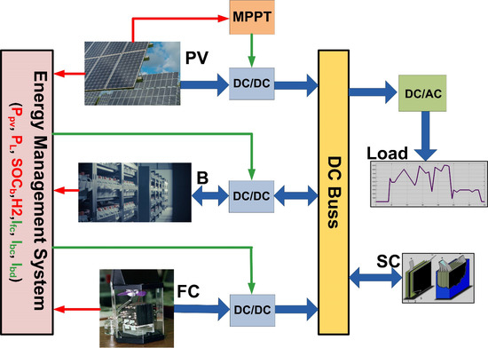
Along the same lines, a number of studies explored the same application with the same configuration; however, compared with the present paper, it was found that all the previous works that have the same components connected the SC to the DC bus through a DC/DC converter to control the charging/discharging of the SC [
28,
29,
30]. By contrast, in the present paper, the SC has been directly connected to the DC, which has two advantages over other connection methods. The first one is reducing the cost of the system through removing one DC/DC converter, and the second advantage is the fast response of the SC to load changing. One of the important parameters for the proton exchange membrane fuel cell (PEMFC) used in this paper is that it works at low temperatures, which gives the chance to enhance its size to achieve maximum power production. The solid oxide fuel cell (SOFC) used for the hybrid system [
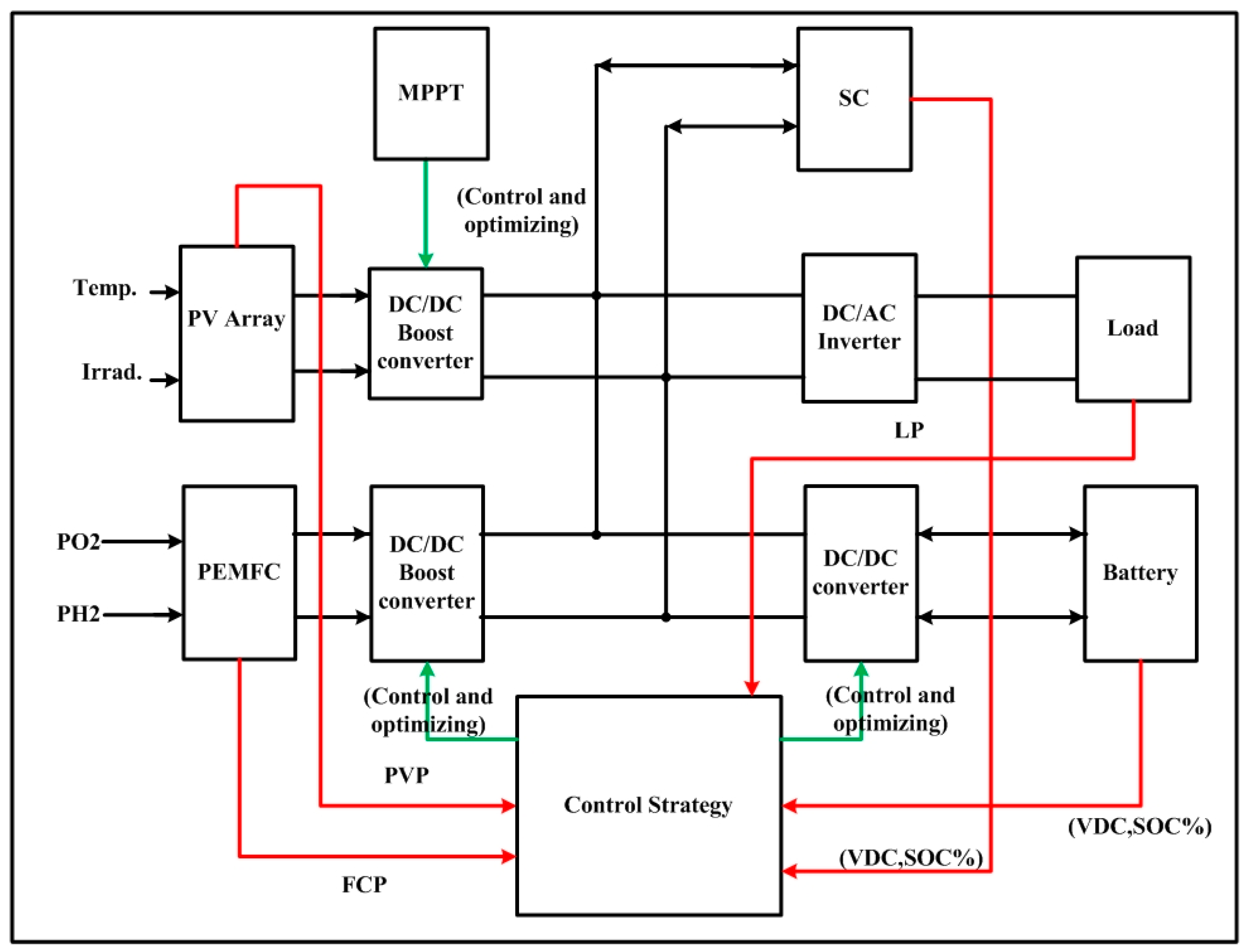
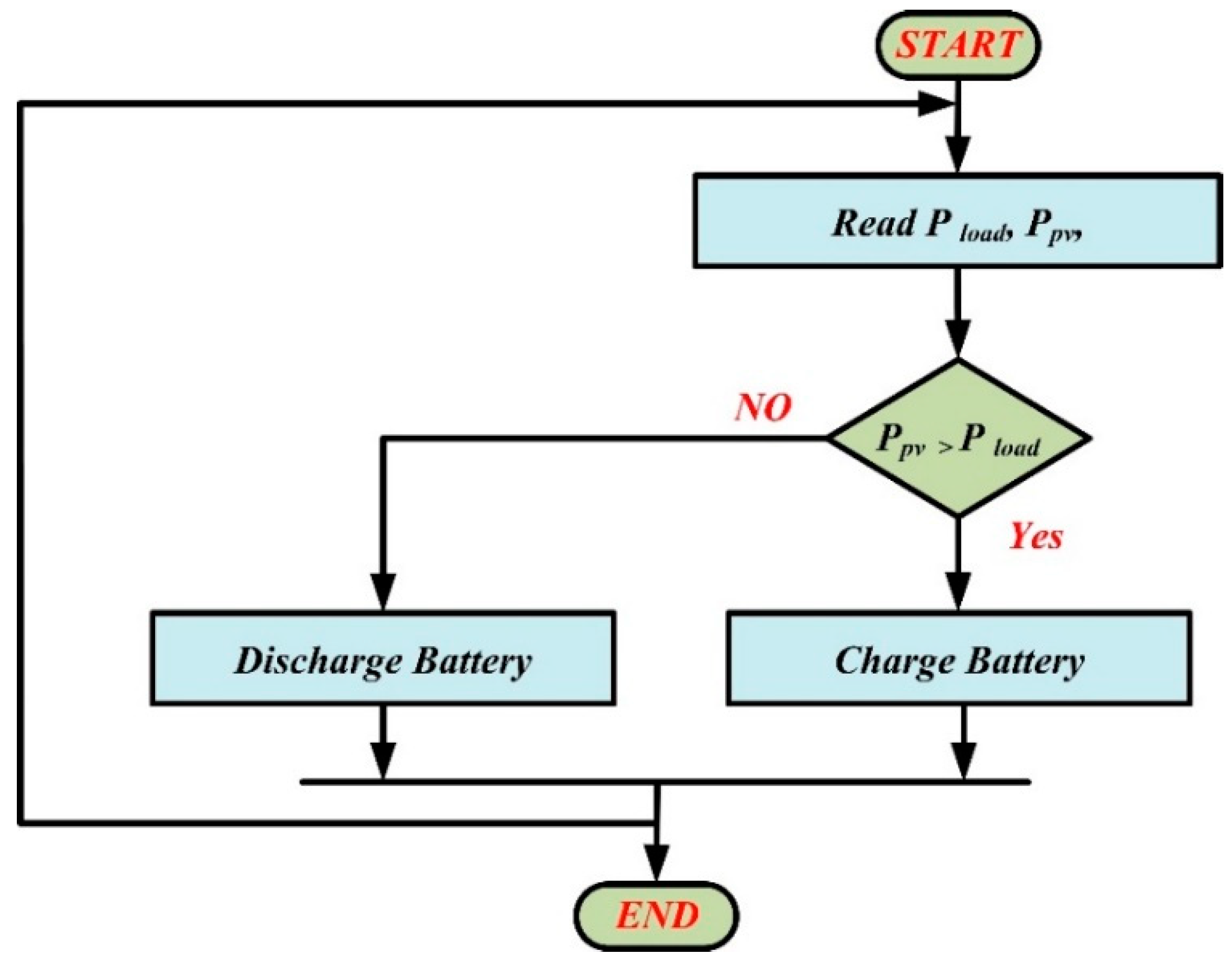
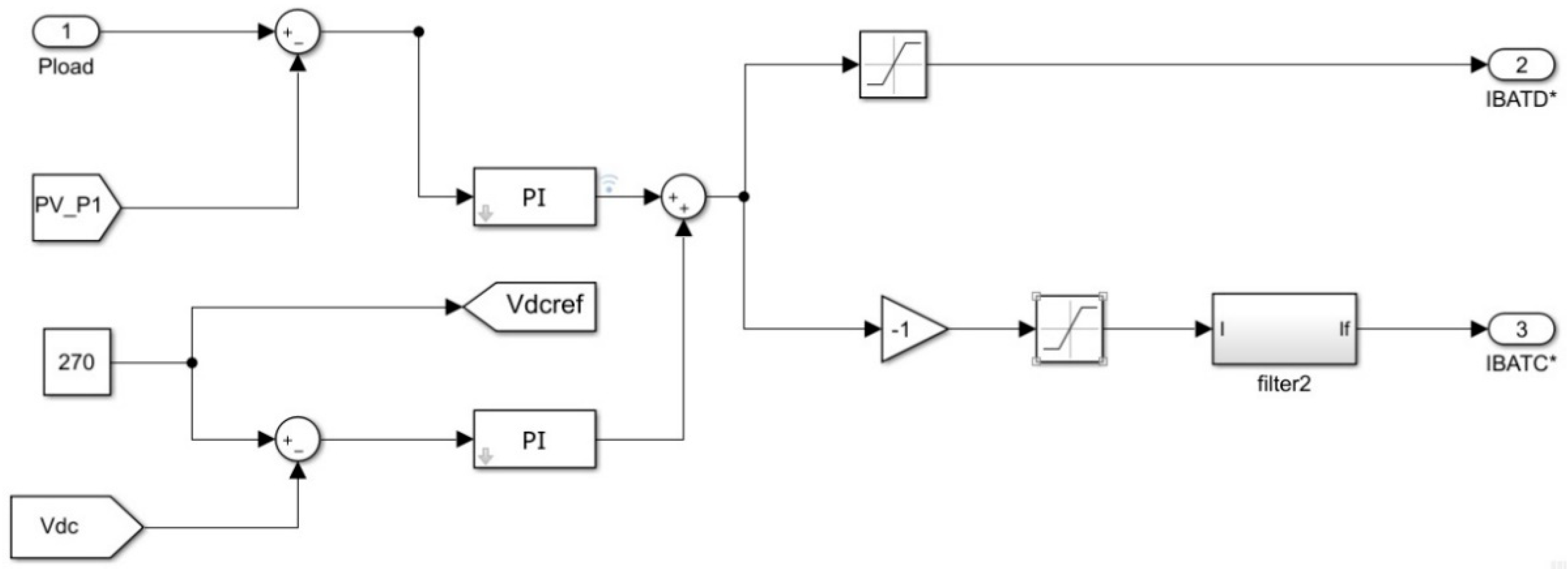
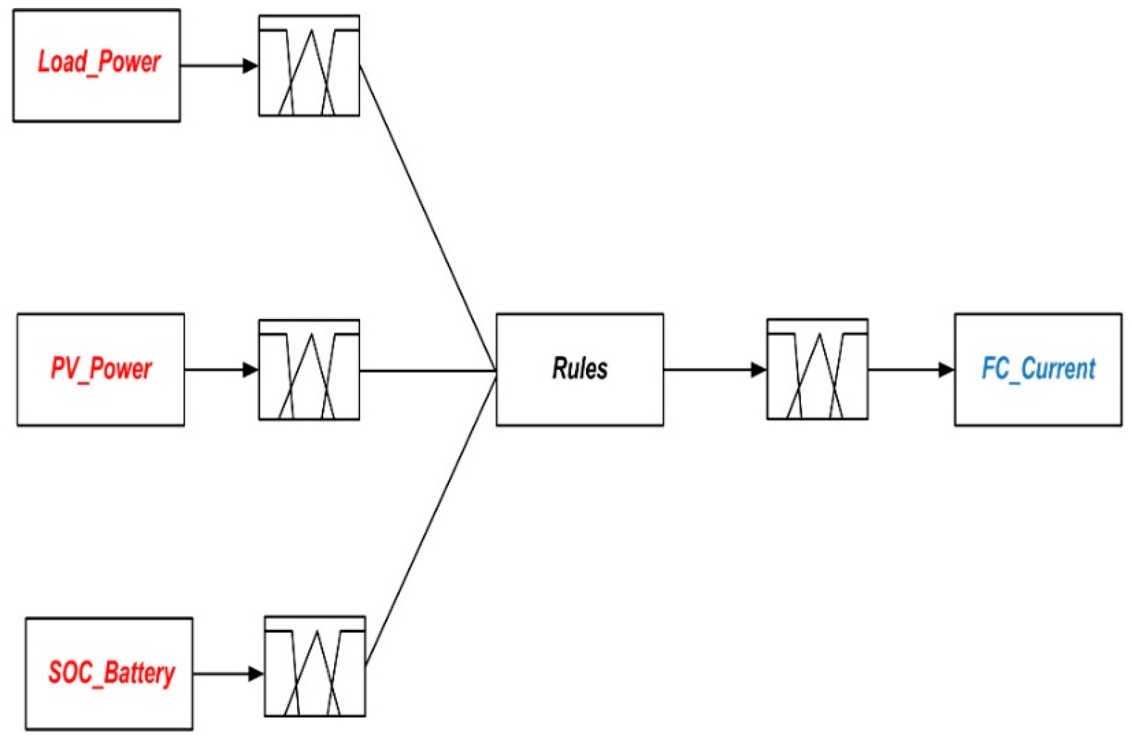
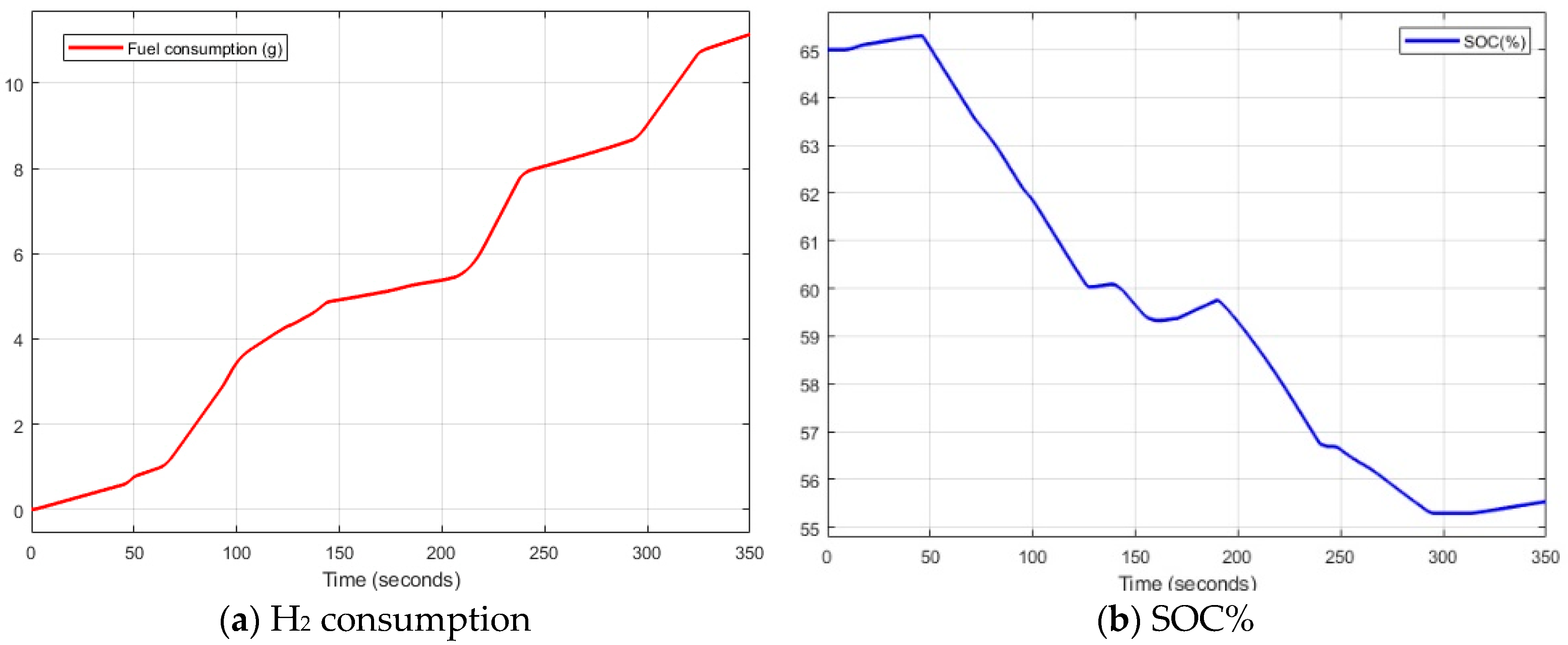
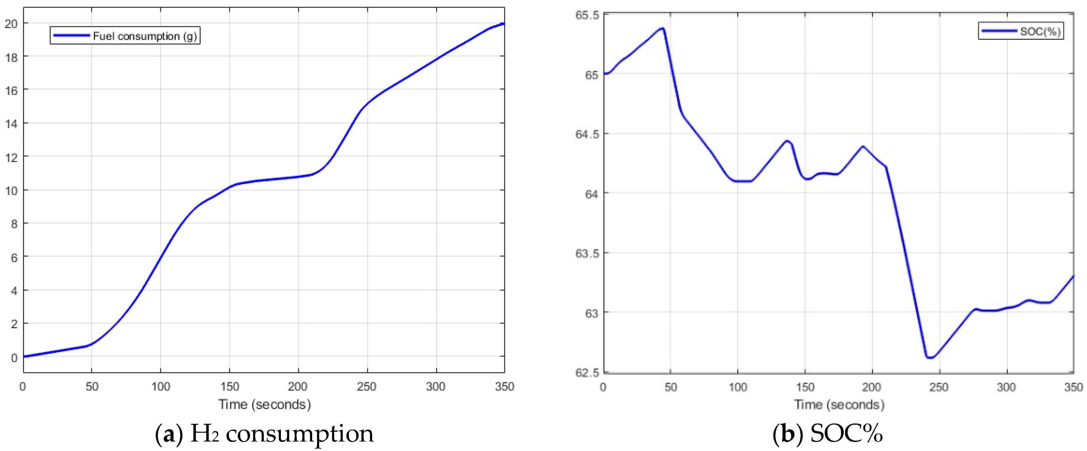
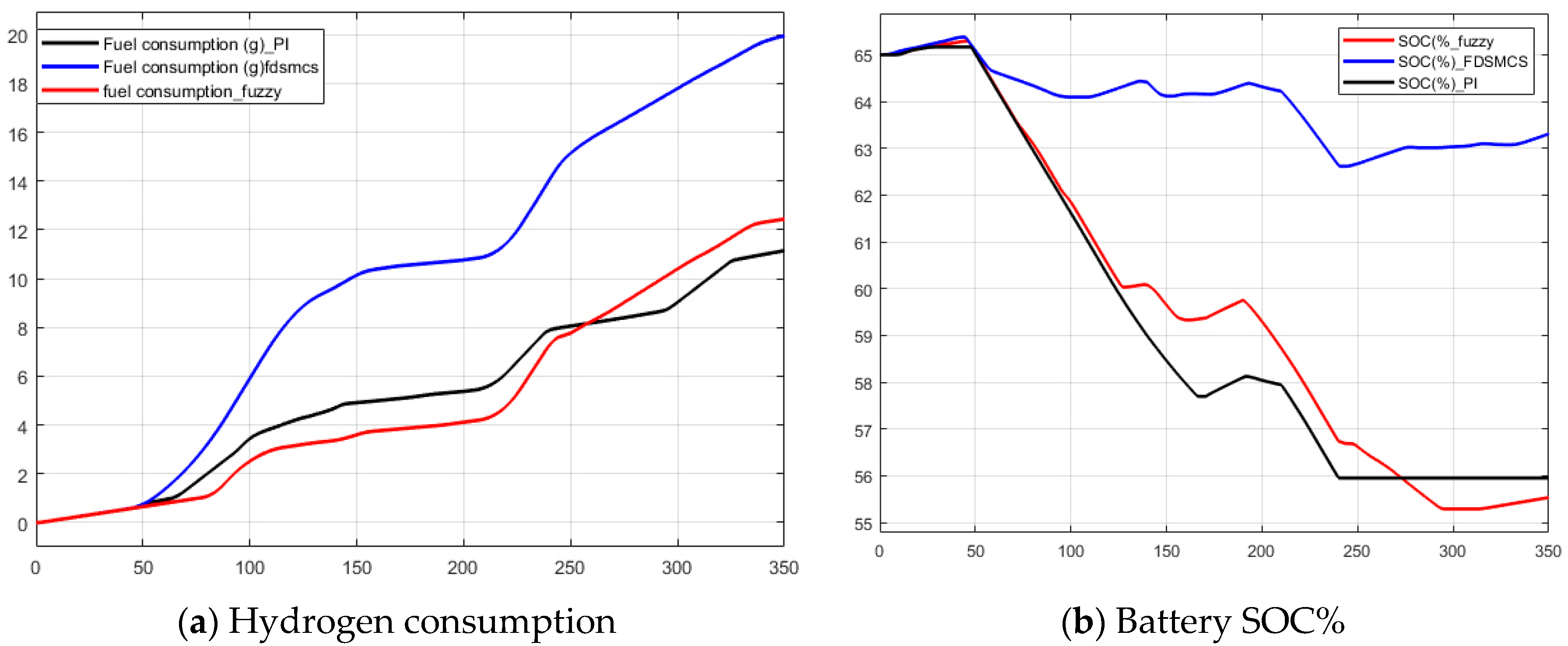
21], by contrast, needs long start-up times and requires insulation and heat dispersion due to temperature concerns. In addition, the PEMFC has higher efficiency, more fuel flexibility, smaller size as it does not require cooling or thermal dissipation, and is less expensive compared to SOFC. The main contribution of this paper is to propose an MG configuration containing PV/FC/B/SC to supply a dump AC variable load with its needed power. It also proposes a classic PI control strategy as an EMS to control the FC current and calculate the hydrogen consumed by the fuel cell. For the proposed system, the PV system decreases the FC hydrogen consumption during day light when it is available, especially in areas of high irradiance values, for a long time. It also gives a chance to increase the size of the clean power generated to decrease greenhouse gasses and global warming, which is good for the environment and climate change. Also, using a battery and a supercapacitor as storage elements gives the system an advantage over individual systems, as the specific power is low, while the specific energy is high—but the supercapacitor has a high specific power and low specific energy [
31,
32]. In this paper, the performance of the system is simulated using two different energy management strategies (fuzzy logic control strategy and high frequency decoupling and state machine control strategies) to validate the proposed PI control strategy. The simulation results show that the PI control strategy is better than the high frequency decoupling and state machine control strategy in terms of hydrogen consumption. Although the hydrogen consumed by the fuzzy logic control strategy is close to the consumed value by PI, the PI control strategy is easy and simple for implementation. The overall system performance proves that the system works efficiently when applied for a three-phase AC variable load. The cost optimization issue was not calculated in this study, and could be considered in future papers. The next sections of this paper present the overall system description of the proposed system structure, system components, the control strategy, results and discussion, and finally, the conclusion.
