Article

Fabrication of Porous Si@C Composites with Core-Shell Structure and Their Electrochemical Performance for Li-ion Batteries

1
School of Chemistry and Chemical Engineering, Chongqing University, Chongqing 400030, China
2
Department of Chemistry, Hengshui University, Hengshui 053000, China
3
Department of Pharmaceutical and Cosmetical Engineering, Woosuk University, Jeollabuk-do 55338, Korea
4
National Oil Reserve Center, Beijing 100000, China
*
Authors to whom correspondence should be addressed.
Batteries 2019, 5(1), 27; https://doi.org/10.3390/batteries5010027
Submission received: 17 January 2019 / Revised: 23 February 2019 / Accepted: 25 February 2019 / Published: 27 February 2019

Abstract

:
The pores in silicon particles can accommodate the volume expansion of silicon during the charging–discharging process. However, pores in silicon particles are easily occupied by carbon during the preparation of silicon/carbon composites. In this paper, sulfur was adsorbed in the pores of porous silicon particles before polyaniline (PANI) coating by in-situ polymerization, so that the pores were preserved in porous silicon@carbon (p-Si/@C) composites after the sublimation of sulfur during carbonization. The microstructure and the electrochemical performances of the obtained p-Si/@C composites were investigated. The results indicate that p-Si/@C composites prepared with a sulfur-melting process show a better high-rate performance than those without a sulfur-melting process. Remarkably, the former show a better capacity retention when returning to a low current density. The reversible capacities of the former were 1178 mAh·g−1, 1055 mAh·g−1, 944 mAh·g−1, and 751 mAh·g−1 at 0.2 A·g−1, 0.3 A·g−1, 0.5 A·g−1, and 1.0 A·g−1, respectively. Moreover, the reversible capacities could return to 870 mAh·g−1, 996 mAh·g−1, and 1027 mAh·g−1 when current densities returned to 0.5, 0.3, and 0.2 A·g−1, respectively.

1. Introduction

With the burgeoning of electric vehicle industries and portable electronics, lithium ion batteries using graphite as anode do not easily satisfy the continuously growing energy demands on the aspects of high energy and power density, because of the low theoretical capacity (372 mAh·g−1) and unsatisfactory high-rate capability of graphite [1,2,3]. Among the anode materials that have been studied, Si has attracted great attention as an alternative negative electrode material due to its high theoretical capacity (~3500 mAh·g−1), low lithiation potential (~0.5 V versus Li/Li+), environment-friendly properties, and natural abundance. However, the key challenge for the application of Si anodes is the huge volume change (~300%) during the lithiation and de-lithiation processes, which leads to the pulverization of the Si anode and even the mechanical disintegration of the working electrode, resulting in the rapid fade of capacity during cycling [4,5,6]. Additionally, many new surfaces continuously form during the cycling, because of the constant pulverization of the Si anode. Hence, the solid-electrolyte interface (SEI) becomes thicker and thicker with the decomposition of the liquid electrolyte and the loss of active lithium whose content is limited by the cathode material in lithium-ion batteries, thus the capacity drops constantly [7,8,9].
In order to improve the electrochemical performance of Si anodes, many efforts have been made, such as preparing nanostructured Si particles with different morphology [10,11,12,13,14], fabricating Si-based composites [15,16,17,18,19], and exploiting novel binders [20,21,22]. Recent works have demonstrated that nano-Si/C composites exhibit an improved cyclic stability and rate capability, because the small size of Si particles can shorten the diffusion distance of lithium ions, and carbon as the buffer layer can effectively alleviate the volume change of Si particles [5,23,24]. Nevertheless, in nano-Si/C composites prepared by the mixing of nano-Si and a carbon precursor and further carbonization (e.g., liquid phase method), the nano-Si particles are difficult to disperse evenly in the carbon matrix due to their characteristic of easy agglomeration, which worsens the electrochemical performance of nano-Si/C composites. Meanwhile, nano-Si/C composites with uniform carbon coating can be obtained via different approaches (e.g., chemical vapor deposition technique [25] and hydrothermal method [26]), but the high production cost and difficulty in large-scale production limit their commercial applications.
From a practical point of view, micro-sized Si particles are easier to mass produce than nano-sized Si, but the former suffer from limited kinetics at high current densities and large internal stress. Many studies have shown that fabricating Si/C composites from porous micro-size Si particles could effectively improve the electrochemical performance of micro-sized Si particles [27,28,29,30]. This is because the porous structure in micro-sized Si particles can provide space for volume expansion, and the external carbon coating not only acts as a buffer layer but also enhances the electronic conductivity of the composites.
In this study, porous micro-size Si particles were obtained from commercial Al-Si alloy composites by acid etching and further ball milling, and then porous Si particles/polyaniline-based carbon (p-Si@C) composites with a core-shell structure were prepared by the sulfur-melting process, in-situ polymerization of aniline, and further carbonization. During the preparation, the sulfur-melting process is a key step. Sulfur is adsorbed to avoid the blockage of pores in porous Si particles by polyaniline (PANI) during polymerization, so that the pores can be preserved in Si particles as core materials of p-Si@C composites. The structure and high-rate performances of p-Si@C composites prepared with and without the sulfur-melting process were compared.

2. Experiment

2.1. Preparation of p-Si@C Composites

Porous micro-size Si particles were obtained by immersing 5 g Al-Si alloy microspheres (Hunan Ningxiang Jiweixin Metal Powder Co., Ltd.) with a particle size distribution of 0.6~10 μm, as shown in Figure S1, into HCl solution (2 M, 500 mL). Next, they were filtrated, washed by de-ionized water, dried, and ball-milled. The conditions of ball-milling were as follows: The revolving velocity was 200 r/min and the time was 2 h. The p-Si particles had a surface area of 62 m2·g−1. Their N2 adsorption/desorption isotherm is shown in Figure S2. The isotherm exhibits type B hysteresis loops, which is typical of slit-shaped pores or the space according to the BDDT (Brunauer-Deming-Deming-Teller) classification [31].
Figure 1 displays the preparation process of p-Si@C composites. Sulfur/p-Si particles composites were prepared before polymerization by a melting–diffusion method. Sublimed sulfur (≥99.5 wt.%, Chengdu Kelong Chemical Reagent Factory) and p-Si particles with a mass ratio of 2:1 were milled for 30 min. The mixture was heated, first, at 155 °C for 8 h under N2, and then the temperature further increased to 200 °C and held for 2 h, during which the heating rate was 0.5 °C·min−1.
The sulfur/p-Si particles composites and aniline monomer (≥99.5 wt.%, Chongqing Chuandong Chemical (group) Co., Ltd.) were added to 180 mL 0.12 M HCl solution (36~38 wt.%, Chongqing Chuandong Chemical (group) Co., Ltd.), then, 30 mL 0.12 M HCl solution containing (NH4)·S2O8 (≥98 wt.%, Chengdu Kelong Chemical Reagent Factory) was continuously dropped into the above solution. The maniline:mp-Si particles was 2:1. The polymerization was carried out in an ice bath, and the polymerization time was 24 h. After washing with deionized water and further drying at 60 °C for 12 h, sulfur/porous Si particles@PANI composites were obtained. p-Si/@C composites were prepared after the carbonization of sulfur/p-Si particles@PANI composites at 900 °C for 2 h under N2 with a heating rate of 1 °C·min−1. The carbon contents in p-Si@C composites were about 45 wt.% according to the results of thermogravimetric analysis, as shown in Figure S3. p-Si/C composites were prepared under the same method without the sulfur-melting process.

2.2. Characterization

SU8020 scanning electron microscopy (SEM) and Tecnai G2 F20 high resolution transmission electron microscopy (HRTEM) were used to characterize the morphology of samples and check the carbon layer on the surface of composites. X-ray diffraction (XRD) patterns were collected on PANalytical X’Pert Powder diffractometer.

2.3. Electrochemical Measurements

The working electrode was prepared by spreading the water slurry of 60 wt.% p-Si@C composites, 20 wt.% multi-walled carbon nanotubes (>91 wt.%, Suzhou Tanfeng Graphene Tech. Inc.), and 20 wt.% sodium carboxymethyl cellulose (CMC2200, DAICEL(CHINA) INVESTMENT CO., LTD.) on copper foil, and drying at 60 °C for 24 h. Next, the electrode was punched into round electrode sheets with a diameter of 13 mm. The loading of p-Si@C composites on the round working electrode sheet was about 1.02 mg·cm−2. Coin-type cells (CR2430) were fabricated in a glovebox filled with argon, using lithium foil (99.9%, China Energy Lithium CO., LTD.) as the counter electrode, Celgard 2325 as the separator, and 1M LiPF6 in a mixture of ethylene carbonate and diethyl carbonate containing fluoroethylene carbonate (LBC3401A4, Shenzhen Capchem Technology Co., LTD.) as the electrolyte. 3~5 batteries was assembled per sample to ensure a high reproducibility of the results.
The high-rate performance and cycling stability of samples were conducted on a Neware battery testing system (Neware Co., Ltd.) within the voltage range of 0.005~2.0 V at current densities of 0.1, 0.2, 0.3, 0.5, and 1 A·g−1 at room temperature. Electrochemical impedance measurements were performed on CHI604E electrochemical system (CH Instruments, Inc.) with the frequency range of 100 k~0.01 Hz.

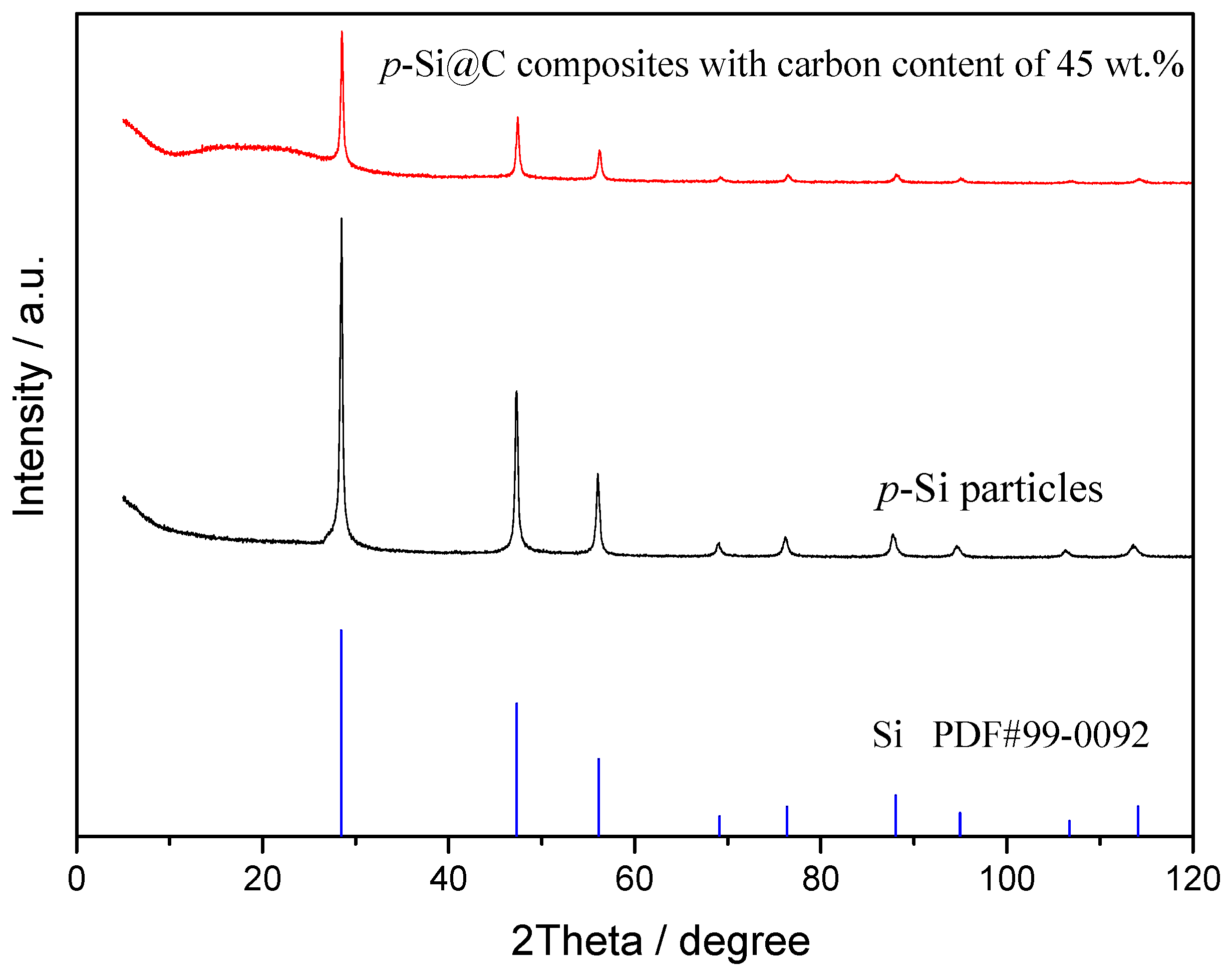
3. Results and Discussion

Figure 2 shows the XRD patterns of p-Si particles and p-Si@C composites with carbon content of 45 wt.%. For p-Si particles, the diffraction peaks at about 28.4°, 47.3°, 56.1°, 69.1°, 76.4°, 88.0°, and 95.0° correspond to (111), (220), (311), (400), (331), (422), and (511) planes, respectively [32,33]. p-Si@C composites exhibited the same diffraction peaks as that of micro-size Si particles, indicating that the crystal structure of p-Si particles was not affected and no new species were produced during the preparation of p-Si@C composites. On the other hand, an unobvious wide diffraction peak at about 20° for p-Si@C composites indicated that the carbon in composites was amorphous.
SEM images of p-Si particles and p-Si@C composites with a carbon content of 45 wt.% are shown in Figure 3. It is apparent that p-Si particles are bulky irregular particles, the p-Si@C composites are still well dispersed, but the particle size increased slightly. In order to observe whether the p-Si particles were evenly coated by carbon layer, energy dispersive spectroscopy (EDS) measurement for p-Si@C composites was carried out. Figure 4 exhibits the distributions of the elements Si and C in the tested area, respectively. As can be seen from EDS spectrum, Si and C elements were observed, and O element was also detected. Oxygen should come from amorphous silica layer formed on surface of silicon particles during the preparation of Si/C composites. From Figure 4, it can also be seen that the distribution of element Si is consistent with most of the shape of the particles in the tested area and the distribution of element C is homogeneous, demonstrating that the Si particles are uniformly coated by PANI-based carbon layer. The results of HRTEM further clarify that crystalline Si particles were well encapsulated by disordered PANI-based carbon layer, as shown in Figure 5b. The thick carbon layer could not only avoid the direct contact of Si particles with electrolyte, but also enhanced the electronic conductivity of composites. Furthermore, the carbon layer as an effective buffer could keep the stable structure of p-Si@C composites during the charge–discharge process. However, for the particle pointed out by an oval, C is the main element. The results indicate that a few pure carbon particles also exist in p-Si@C composites, because of the high mass ratio of aniline monomer and p-Si particles during polymerization.
The results of galvanostatic charge–discharge test are shown in Figure 6. From Figure 6a, the reversible capacity of p-Si particles faded quickly with the increase of the charge–discharge rate, although they exhibited a high reversible capacity at 0.1 A·g−1. Moreover, the coulombic efficiency of p-Si particles obtained from the charge and discharge capacity was relatively low. The coulombic efficiency at 0.2 A·g1 increases slowly to 95 from 85% implying the continuous consumption of Li+ and formation of SEI (Solid electrolyte interface) film on the surface of p-Si particles during cycling. Note that, the reversible capacities of Si/C composites prepared with and without the sulfur-melting process all showed a much higher capacity when the current densities increased to 1 A·g−1 from 0.2 A·g−1. Moreover, when the current densities returned to 0.5, 0.3, and 0.2 A·g−1 from 1 A·g−1, the reversible capacities of Si/C composites could be returned to their original level. Moreover, the coulombic efficiencies of Si/C composites prepared with and without sulfur-melting process remain above 98% and 96% after the first cycle at 0.1 A·g1, respectively, indicating the formation of a stable SEI film. These results indicate that PANI-based carbon layer in Si/C composites can effectively alleviate the volume expansion of silicon during charging–discharging process, so that the integrity of the electrode can be maintained.
On the other hand, with the increase of the charge–discharge rate, the reversible capacities of p-Si@C composites prepared with the sulfur-melting process were higher than that without the sulfur-melting process. For p-Si@C composites prepared with the sulfur-melting process, their reversible capacities were 1178, 1055, 944, and 751 mAh·g−1 at 0.2, 0.3, 0.5, and 1.0 A·g−1, respectively. Interestingly, when the current densities return to 0.5, 0.3, and 0.2 A·g−1, the discharge capacities return to 870, 996, and 1027 mAh·g−1, respectively (Figure 6a). Furthermore, the electrochemical performances of p-Si@C composites with different carbon contents were also investigated. With the increase of carbon content to 51 from 45 wt.%, the p-Si@C composites still displayed a good high-rate performance (Figure S4), although the capacities decreased with the increase of the carbon content in composites. The capacity retention for p-Si@C composites with a carbon content of 45 wt.% is about 65% after 120 cycles at 0.5 A·g−1, and that reaches 76% after 120 cycles at 0.2 A·g−1 (Figure 6b), indicating a good cycling performance. These results demonstrate that pore structure in inner Si particles in p-Si@C composites also plays an important role in the improvement of the electrochemical performance. Furthermore, the outer PANI-based carbon-coating layers serves as an effective buffer layer. The high-rate capability of p-Si@C composites is higher than that of the nano-silicon/polyaniline composites which has been reported [34], but the cycling performance and the initial coulombic efficiency should be improved further.
Figure 7 displays the results of a.c. impedance measurement, and Bode and local Nyquist plots are shown in Figure S5. As revealed in Figure 7 and Figure S5, all the Nyquist plots comprise two semicircles in the relative high frequency range corresponding to the two time constants in the Bode plots, and a sloping straight line in the range of relative low frequency. In order to facilitate the comparison, the impedance spectra are simulated by Z-view software and the equivalent circuit is shown in the inset of Figure 7. In the equivalent circuit, Rs is the solution resistance, Rf corresponding to the time constant (τ1) at high frequency in Figure S5 represents the resistance of SEI film, Rct corresponding to the time constant (τ2) from high to middle frequencies in Figure S5 is the charge-transfer resistance [35,36]. W (referring to the Warburg impedance) corresponding to the sloping line in the low-frequency region is related to the diffusion of lithium ions in electrode materials [37]. The simulation results are shown in Table 1.
The diffusion coefficient of lithium ion (DLi) is calculated by Equation 1 and 2 [38]. In the following formula, R (molar gas constant) is 8.314 J·mol−1·K−1; T (absolute temperature) is 298 K; F (Faraday constant) is 96,485 C·mol−1; A (the area of the electrode surface) is about 1.33 cm2; ω represents the angular frequency; n (=1) represents the number of electrons transferred in the half-reaction for the redox couple; cLi (the molar concentration of Li+) is 4.17 × 10⁻³ mol·cm−3, and σ (Warburg impedance coefficient) is obtained from the slope of the lines in Figure 8. The value of DLi is also listed in Table 1.
D L i = ( R T ) 2 2 ( A n 2 F 2 c L i σ ) 2
Z r e = R s + R c t + σ ω 1 2
As seen in Table 1, p-Si particles have larger Rf than p-Si@C composites with carbon content of 45 wt.%, because of the continuous formation of thick SEI film on the surface of p-Si particles exposed to electrolytes during the charge–discharge process. This is because the thick and whole carbon-coating layer for p-Si@C composites with carbon content of 45 wt.% can avoid direct contact between Si particles and electrolytes, and is helpful for the formation of stable and thin SEI film. On the other hand, the larger DLi of p-Si@C composites with a carbon content of 45 wt.% than that of p-Si particles should also be attributed to the stable and thin SEI film. The results further demonstrate that introducing a carbon-coating layer with an appropriate thickness into p-Si@C composites can improve their electrochemical performances.

4. Conclusions

p-Si@C composites with core-shell structure have been fabricated by the following steps: Adsorbing molten sulfur, coating PANI by in-situ polymerization, and further carbonization. During the preparation, the adsorption of sulfur was done to avoid the blockage of pores in Si particles by PANI during polymerization, so that the pores can be preserved in Si particles as core materials of p-Si@C composites. Moreover, their electrochemical performances were further investigated, and p-Si@C composites prepared with the sulfur-melting process exhibited a better high-rate performance and cycling stability than p-Si/C composites prepared without the sulfur-melting process. For p-Si@C composites prepared with the sulfur-melting process, the pore structure in inner p-Si particles could accommodate the volume change and alleviate the internal stress of particles, and the external carbon coating layers with proper thickness offer good electrical contact and served as an effective buffer layer during the charge–discharge process.

Supplementary Materials

The following are available online at https://www.mdpi.com/2313-0105/5/1/27/s1.

Author Contributions

Conceptualization, X.X.; Investigation, Y.X.; Methodology, W.L.; Supervision, S.Z.; Validation, N.L.

Funding

This research was funded by the Chongqing science and technology project (No. cstc2018jszx-cyzdX0087), Chongqing Foundation and Advanced Research Projects (No. cstc2016jcyjA0462) and the Fundamental Research Funds for the Central Universities (No. 106112017CDJXFLX0014, 2018CDXYHG0028) for financial assistance.

Conflicts of Interest

The authors declare no conflict of interest.

References

  1. Jang, J.; Kang, I.; Yi, K.-W.; Cho, Y.W. Highly conducting fibrous carbon-coated silicon alloy anode for lithium ion batteries. Appl. Surf. Sci. 2018, 454, 277–283. [Google Scholar] [CrossRef]
  2. Firnadya, S.A.; Syahrial, A.Z.; Subhan, A. Enhancing battery performance by nano Si addition to Li4Ti5O12 as anode material on lithium-ion battery. Ionics 2018, 24, 1029–1037. [Google Scholar] [CrossRef]
  3. Yao, M.; Zeng, Z.; Zhang, H.; Yan, J.; Liu, X. Electrophoretic deposition of carbon nanofibers/silicon film with honeycomb structure as integrated anode electrode for lithium-ion batteries. Electrochim. Acta 2018, 281, 312–322. [Google Scholar] [CrossRef]
  4. Zhao, Y.; Yang, L.; Zuo, Y.; Song, Z.; Liu, F.; Li, K.; Pan, F. Conductive Binder for Si Anode with Boosted Charge Transfer Capability via n-Type Doping. ACS Appl. Mater. Interfaces 2018, 10, 27795–27800. [Google Scholar] [CrossRef] [PubMed]
  5. Jia, H.; Zheng, J.; Song, J.; Luo, L.; Yi, R.; Estevez, L.; Zhao, W.; Patel, R.; Li, X.; Zhang, J.-G. A novel approach to synthesize micrometer-sized porous silicon as a high performance anode for lithium-ion batteries. Nano Energy 2018, 50, 589–597. [Google Scholar] [CrossRef]
  6. Zhao, S.; Yao, C.; Sun, L.; Xian, X. Si/polyaniline-based porous carbon composites with an enhanced electrochemical performance as anode materials for Li-ion batteries. Ionics 2018, 24, 1039–1048. [Google Scholar] [CrossRef]
  7. Zhang, X.; Huang, M.; Yang, C.; Dai, G.; Huang, J. Fabrication of porous Si/nitrogen doped carbon composite and its enhanced lithium storage capability. Mater. Chem. Phys. 2017, 201, 302–310. [Google Scholar] [CrossRef]
  8. Holtstiege, F.; Wilken, A.; Winter, M.; Placke, T. Running out of lithium? A route to differentiate between capacity losses and active lithium losses in lithium-ion batteries. Phys. Chem. Chem. Phys. 2017, 19, 25905–25918. [Google Scholar] [CrossRef] [PubMed]
  9. Smith, A.J.; Burns, J.C.; Xiong, D.; Dahn, J.R. Interpreting High Precision Coulometry Results on Li-ion Cells. J. Electrochem. Soc. 2011, 158, A1136–A1142. [Google Scholar] [CrossRef]
  10. Jeong, M.-G.; Du, H.L.; Islam, M.; Lee, J.K.; Sun, Y.-K.; Jung, H.-G. Self-Rearrangement of Silicon Nanoparticles Embedded in Micro-Carbon Sphere Framework for High-Energy and Long-Life Lithium-Ion Batteries. Nano Lett. 2017, 17, 5600–5606. [Google Scholar] [CrossRef] [PubMed]
  11. Chiu, K.-F.; Su, S.-H.; Leu, H.-J.; Wu, C.-Y. Silicon thin film anodes coated on micron carbon-fiber current collectors for lithium ion batteries. Surf. Coat. Technol. 2015, 267, 70–74. [Google Scholar] [CrossRef]
  12. Yi, Y.; Lee, G.-H.; Kim, J.-C.; Shim, H.-W.; Kim, D.-W. Tailored silicon hollow spheres with Micrococcus for Li ion battery electrodes. Chem. Eng. J. 2017, 327, 297–306. [Google Scholar] [CrossRef]
  13. Balderas-Valadez, R.F.; Antúnez, E.E.; Olive-Méndez, S.F.; Pacholski, C.; Campos-Alvarez, J.; Bokhimi, X.; Agarwal, V. Porous silicon pillar and bilayer structure as a nucleation center for the formation of aligned vanadium pentoxide nanorods. Ceram. Int. 2017, 43, 8023–8030. [Google Scholar] [CrossRef]
  14. Zhang, F.; Wan, L.; Chen, J.; Li, X.; Yan, X. Crossed carbon skeleton enhances the electrochemical performance of porous silicon nanowires for lithium ion battery anode. Electrochim. Acta 2018, 280, 86–93. [Google Scholar] [CrossRef]
  15. Liu, X.; Wang, Z.; Guo, H.; Li, X.; Zhou, R.; Zhou, Y. Chitosan: A N-doped carbon source of silicon-based anode material for lithium ion batteries. Ionics 2017, 23, 2311–2318. [Google Scholar] [CrossRef]
  16. Yi, Z.; Lin, N.; Xu, T.; Qian, Y. TiO2 coated Si/C interconnected microsphere with stable framework and interface for high-rate lithium storage. Chem. Eng. J. 2018, 347, 214–222. [Google Scholar] [CrossRef]
  17. Carbonari, G.; Maroni, F.; Birrozzi, A.; Tossici, R.; Croce, F.; Nobili, F. Synthesis and characterization of Si nanoparticles wrapped by V2O5 nanosheets as a composite anode material for lithium-ion batteries. Electrochim. Acta 2018, 281, 676–683. [Google Scholar] [CrossRef]
  18. Assresahegn, B.D.; Ossonon, B.D.; Bélanger, D. Graphene nanosheets and polyacrylic acid grafted silicon composite anode for lithium ion batteries. J. Power Sources 2018, 391, 41–50. [Google Scholar] [CrossRef]
  19. Zhou, Z.; Zhang, Y.; Hua, Y.; Dong, P.; Lin, Y.; Xu, M.; Wang, D.; Li, X.; Han, L.; Duan, J. Molten salt electrolytic synthesis of silicon-copper composite nanowires with enhanced performances as lithium ion battery anode. J. Alloys Compd. 2018, 751, 307–315. [Google Scholar] [CrossRef]
  20. Zhao, X.; Yim, C.-H.; Du, N.; Abu-Lebdeh, Y. Shortly Branched, Linear Dextrans as Efficient Binders for Silicon/Graphite Composite Electrodes in Li-Ion Batteries. Ind. Eng. Chem. Res. 2018, 57, 9062–9074. [Google Scholar] [CrossRef]
  21. Lee, S.-Y.; Choi, Y.; Hong, K.-S.; Lee, J.K.; Kim, J.-Y.; Bae, J.-S.; Jeong, E.D. Influence of EDTA in poly(acrylic acid) binder for enhancing electrochemical performance and thermal stability of silicon anode. Appl. Surf. Sci. 2018, 447, 442–451. [Google Scholar] [CrossRef]
  22. Zhang, G.; Yang, Y.; Chen, Y.; Huang, J.; Zhang, T.; Zeng, H.; Wang, C.; Liu, G.; Deng, Y. A Quadruple-Hydrogen-Bonded Supramolecular Binder for High-Performance Silicon Anodes in Lithium-Ion Batteries. Small 2018, 14, 1801189. [Google Scholar] [CrossRef] [PubMed]
  23. Matsumoto, T.; Kimura, K.; Nishihara, H.; Kasukabe, T.; Kyotani, T.; Kobayashi, H. Fabrication of Si nanopowder from Si swarf and application to high-capacity and low cost Li-ion batteries. J. Alloys Compd. 2017, 720, 529–540. [Google Scholar] [CrossRef]
  24. Liang, G.; Qin, X.; Zou, J.; Luo, L.; Wang, Y.; Wu, M.; Zhu, H.; Chen, G.; Kang, F.; Li, B. Electrosprayed silicon-embedded porous carbon microspheres as lithium-ion battery anodes with exceptional rate capacities. Carbon 2018, 127, 424–431. [Google Scholar] [CrossRef]
  25. Ding, X.; Wang, H.; Liu, X.; Gao, Z.; Huang, Y.; Lv, D.; He, P.; Huang, Y. Advanced anodes composed of graphene encapsulated nano-silicon in a carbon nanotube network. RSC Adv. 2017, 7, 15694–15701. [Google Scholar] [CrossRef] [Green Version]
  26. Ruttert, M.; Holtstiege, F.; Huesker, J.; Boerner, M.; Winter, M.; Placke, T. Hydrothermal-derived carbon as a stabilizing matrix for improved cycling performance of silicon-based anodes for lithium-ion full cells. Beilstein J. Nanotechnol. 2018, 9, 2381–2395. [Google Scholar] [CrossRef] [PubMed]
  27. Su, J.; Zhang, C.; Chen, X.; Liu, S.; Huang, T.; Yu, A. Carbon-shell-constrained silicon cluster derived from Al-Si alloy as long-cycling life lithium ion batteries anode. J. Power Sources 2018, 381, 66–71. [Google Scholar] [CrossRef]
  28. Zhou, X.; Chen, S.; Zhou, H.; Tang, J.; Ren, Y.; Bai, T.; Zhang, J.; Yang, J. Enhanced lithium ion battery performance of nano/micro-size Si via combination of metal-assisted chemical etching method and ball-milling. Microporous Mesoporous Mater. 2018, 268, 9–15. [Google Scholar] [CrossRef]
  29. Zhang, Y.; Du, N.; Chen, Y.; Lin, Y.; Jiang, J.; He, Y.; Lei, Y.; Yang, D. Carbon dioxide as a green carbon source for the synthesis of carbon cages encapsulating porous silicon as high performance lithium-ion battery anodes. Nanoscale 2018, 10, 5626–5633. [Google Scholar] [CrossRef] [PubMed]
  30. Guo, S.; Hu, X.; Hou, Y.; Wen, Z. Tunable Synthesis of Yolk–Shell Porous Silicon@Carbon for Optimizing Si/C-Based Anode of Lithium-Ion Batteries. ACS Appl. Mater. Interfaces 2017, 9, 42084–42092. [Google Scholar] [CrossRef] [PubMed]
  31. Zhao, S.; Ka, O.; Xian, X.; Sun, L.; Wang, J. Effect of primary crystallite size on the high-rate performance of Li4Ti5O12 microspheres. Electrochim. Acta 2016, 206, 17–25. [Google Scholar] [CrossRef]
  32. Yu, H.; Liu, X.; Chen, Y.; Liu, H. Carbon-coated Si/graphite composites with combined electrochemical properties for high-energy-density lithium-ion batteries. Ionics 2016, 22, 1847–1853. [Google Scholar] [CrossRef]
  33. Zhuang, X.; Zhang, Y.; He, L.; Zhu, Y.; Shi, Q.; Wang, Q.; Song, G.; Yan, X.; Li, L. Strategy to form homogeneously macroporous Si as enhanced anode material of Li-ion batteries. J. Alloys Compd. 2018, 731, 1–9. [Google Scholar] [CrossRef]
  34. Feng, M.; Tian, J.; Xie, H.; Kang, Y.; Shan, Z. Nano-silicon/polyaniline composites with an enhanced reversible capacity as anode materials for lithium ion batteries. J. Solid State Electrochem. 2015, 19, 1773–1782. [Google Scholar] [CrossRef]
  35. Kim, N.; Oh, C.; Kim, J.; Kim, J.S.; Jeong, E.D.; Bae, J.S.; Hong, T.E.; Lee, J.K. High-Performance Li-Ion Battery Anodes Based on Silicon-Graphene Self-Assemblies. J. Electrochem. Soc. 2017, 164, A6075–A6083. [Google Scholar] [CrossRef]
  36. Gómez-Cámer, J.L.; Thuv, H.; Novák, P. Electrochemical study of Si/C composites with particulate and fibrous morphology as negative electrodes for lithium-ion batteries. J. Power Sources 2015, 294, 128–135. [Google Scholar] [CrossRef]
  37. Wang, J.P.; Wang, C.Y.; Zhu, Y.M.; Wu, N.N.; Tian, W.H. Electrochemical stability of optimized Si/C composites anode for lithium-ion batteries. Ionics 2015, 21, 579–585. [Google Scholar] [CrossRef]
  38. Zhao, S.; Zhang, M.M.; Xian, X.C.; Ka, O.; Wang, Z.H.; Wang, J. Insight into the formation mechanism of Li4Ti5O12 microspheres obtained by a CTAB-assisted synthetic method and their electrochemical performances. J. Mater. Chem. A 2017, 5, 13740–13747. [Google Scholar] [CrossRef]
Figure 1. Schematic illustration of preparation of p-Si@C composites.
Batteries 05 00027 g001
Figure 2. XRD patterns of p-Si particles and p-Si@C composites with carbon content of 45 wt.%.
Batteries 05 00027 g002
Figure 3. SEM images of (a) p-Si particles and (b) p-Si@C composites with carbon content of 45 wt.%.
Batteries 05 00027 g003
Figure 4. EDS elemental mapping (Si and C) and EDS spectrum for the selected area of the p-Si@C composites with carbon content of 45 wt.%.
Batteries 05 00027 g004
Figure 5. HRTEM images of (a) p-Si particles and (b) p-Si@C composites with carbon content of 45 wt.%.
Batteries 05 00027 g005
Figure 6. (a) High-rate capabilities for p-Si particles, PANI-based carbon and p-Si@C composites prepared with and without sulfur-melting process and (b) cycling stability of p-Si@C composites with carbon content of 45 wt.% at 0.2 and 0.5 A·g1.
Batteries 05 00027 g006
Figure 7. Nyquist plots for p-Si particles and p-Si@C composites.
Batteries 05 00027 g007
Figure 8. Z’ plots against ω−1/2 at the low frequency region of EIS (electrochemical impedance spectroscopy).
Batteries 05 00027 g008
Table 1. Equivalent circuit parameters obtained from the results of Figure 7 and Figure 8.
SamplesRsRfRctσDLi/cm2·s−1
p-Si particles3.78441.64118.2157.73.89 × 10−14
p-Si@C composites3.88113.2735.9561.382.57 × 10−13

