1. Introduction
Today, lithium-ion batteries (LIBs) are by far the most common energy storage solutions in mobile devices such as electric vehicles (EVs), drones, computers, and phones. Thanks to recent advances in LIB technology the EV market is growing, a trend that is expected to continue [
1]. With the growth of the LIB market, LIB testing instruments, LIB characterization and modeling methods, as well as, measuring techniques applied to LIBs may be improved. Specifically, techniques such as hybrid pulse power current (HPPC), incremental capacity analysis (ICA), galvanic intermittent titration technique (GITT), and electrochemical impedance spectroscopy (EIS) can advance LIB testers. Nonetheless, these techniques demand modern instrumentation and measurement accuracy.
LIBs are designed and operated under dc current principles [
2], and for that reason traditionally ac currents have been recommended to be reduced by manufactures [
3]. Therefore, the main LIB technological advances have been focusing essentially in dc current related features, like for instance life cycle or charge acceptance. Probably for this reason, for large LIB cells intended for automotive applications, particularly for frequencies above 200 Hz, no LIB tester with ac current capability can be found among major manufactures [
4,
5,
6,
7], leading to tailor-made LIB testers like the one described in [
8] and in this paper. However, in real applications LIBs unavoidably have to interact with switch-mode power converters (SMPC). Subsequently, this means that LIBs may be subjected to a wide variety of harmonic currents. An example of this can be seen in [
9] where it is reported that frequencies from 150 Hz to up to several kHz, with magnitudes up to 17 A, were observed in a commercial hybrid bus. Even though off-the-shelf commercial testers with the above mentioned ac current capability cannot be found on the market, research requiring them has become popular in recent years. Different examples can be found in the literature. For instance, in [
10,
11,
12], the impact of ac currents on the life expectancy of LIBs is investigated. In [
13,
14,
15,
16], ac currents superimposed to the dc currents were used in an attempt to improve charging performance. In [
17] it is reported that charge acceptance has increased in lead-acid batteries by pre-commissioning them with ac current. In [
18,
19,
20,
21], ac current is used as a heating mechanism for subzero temperature battery applications. In this context, considering large LIB cells intended to be used in the automotive sector, an experimental setup was designed to enable investigations related to the above mentioned topics.
This paper details the design and performance of an experimental setup with ac current capability for evaluating large LIB cells. The evaluation of LIB cell performance depends on characterization methods which may be repetitive and often time consuming [
22]. Additionally, for a fair cell performance comparison, the characterization methods must be carried out with precise voltage and current measurements. Thus, this paper focuses on the precision of such measurements and on their impact on the different characterization methods. The experimental setup accommodates the most relevant LIB cell characterization methods: capacity and energy efficiency characterizations, HPPC, ICA, and GITT, experimental tests procedures which are shown in this paper.
The paper is organized as follows: In
Section 2.1, the design of the power system is presented; in
Section 2.2, the instruments used for the measurement system are presented, and measurement errors of the setup are addressed; in
Section 2.3, the coordination between the power and the measurement systems required to ensure safe operation is explained. In
Section 3, LIB cells at beginning of life (BOL) are used to test the setup’s performance when operated with the different characterization methods (capacity cycle, HPPC, ICA, and GITT). Finally, in
Section 4, preliminary capacity fading results are presented.
2. Experimental Setup and Implemented Configuration
The setup was designed to test LIB cells intended for EV traction applications with large charging rates (C-rate), i.e., 28 Ah. C-rate may be defined as the rate of discharge current from a full energy charge to an entire energy discharge in one hour. The experimental setup specifications can be found in
Table 1. To safely achieve the specifications of
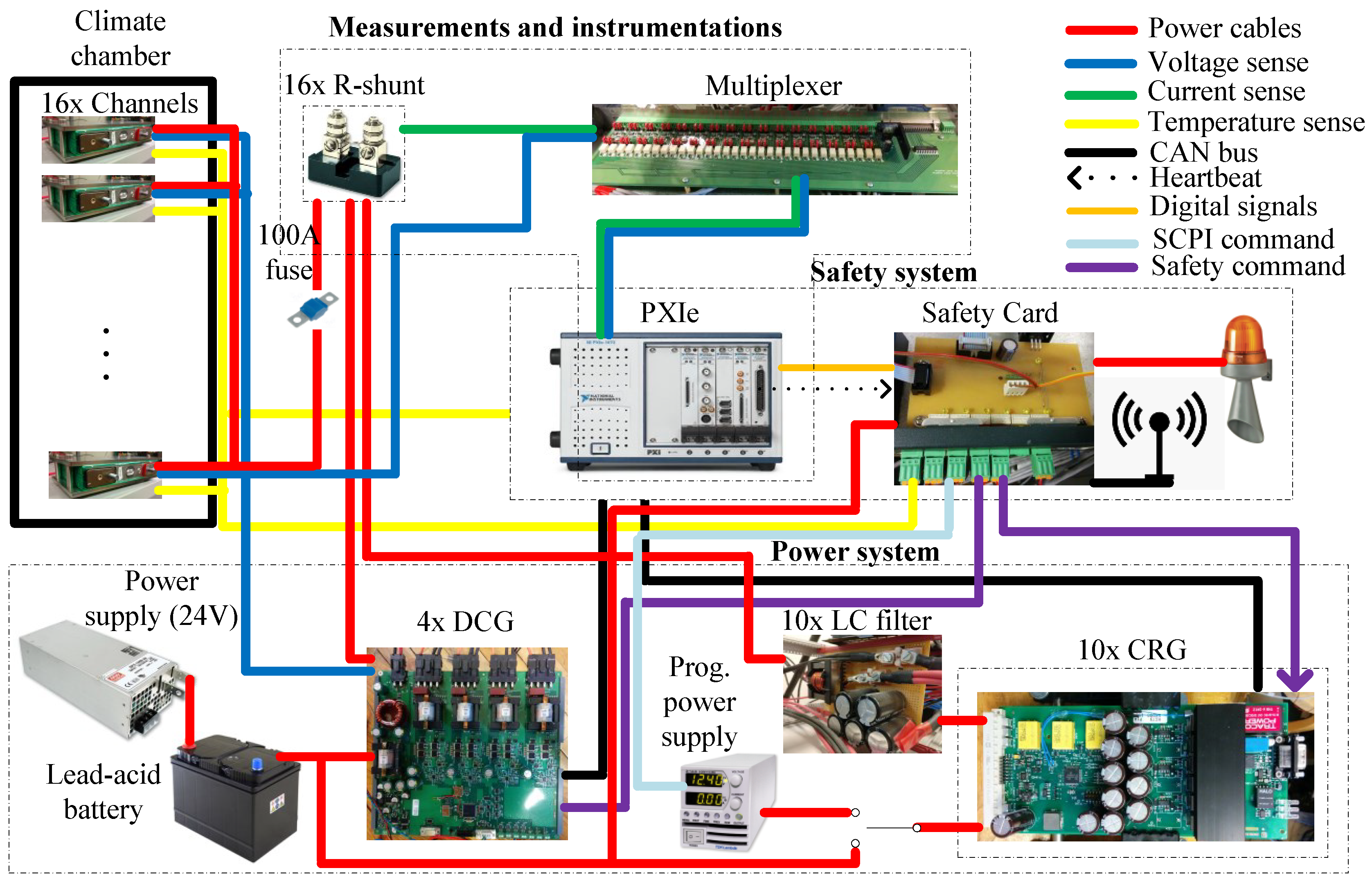
Table 1, the setup configuration depicted in
Figure 1 was constructed.
2.1. Power System
The 16 independent channels may supply dc, ac, or ac superimposed on a dc current. To produce such current, two circuit boards were used, one dedicated to generate dc current (DCG) and one which could generate both dc and ac current, the latter is here called current ripple generator (CRG). The DCG board is described in [
23]. Both circuit boards are fed with 24 V by the 1.5 kW power supply from Mean Well (Mean Well Enterprises CO., LTD., New Taipei City, Taiwan), which is connected in parallel with lead-acid batteries. This configuration enables the charge cycle currents to flow back-and-forth, i.e., from the lead-acid batteries to the cells as well as from the cells to the two lead-acid batteries. This makes the setup more energy efficient, as the 24 V power supply only needs to compensate for the losses of the charge cycle process. In addition, this configuration made possible for the setup to temporarily provide high currents (while maintaining a stable voltage) to the cells and to downsize the 24 V power supply.
The setup is equipped with four DCGs and ten CRGs. Each DCG has itself four independent dc-dc converters (hence, the total 16 channels) capable of ±40 A each. The DGC and CRG boards were connected in a power panel with 16 outputs, one per LIB cell. This allowed the boards to be interchangeable, meaning that any channel may be connected to any board. Also, this allowed to group the boards in the same setup’s channel, for instance, one DCG plus one CRG or two CRGs in parallel. This allows for further current capability per channel, which is limited by 100 A fuses. The use of filters to connect both the CRG and DCG to the cells is addressed in [
24].
The CRG is a three-phase voltage source converter (VSC) equipped with six IPP120N20NFD MOSFETs from Infineon (Infineon Technologies AG, Neubiberg, Germany). The MOSFETS can handle 200 V nominally, are capable of continuously delivering 20 A with the present heatsink. When the three-phase legs are connected in parallel, this configuration allowed the CRG to continuously generate ±60 A. Each CRG may be fed by the 24 V power supply or by a dedicated Z+ TDK programable power supply from TDK-Lambda (TDK-Lambda Corporation, Tokyo, Japan), depending on whether it is operated alone or in cooperation with a DCG. The CRG is controlled using the microcontroller TMS320F28065 Picolo
TM from Texas Instruments allowing a switching frequency up to 70 kHz. The TMS320F28065 Picolo
TM was programmed in C-language using Code Composer Studio (Code composer studio is a registered trademark of Texas instruments, Dallas, TX, USA). The C-code can be found in appendix C of [
25]. The generated ac current is achieved using a proportional integral (PI) close-loop current control and pulse width modulation (PWM). The CRG’s output current is filtered by a low pass LC filter to minimize the current ripple due to switching action of the CRG. The different current shapes, namely sinusoidal, triangular, and square, were pre-programmed and may be selected in the setup’s graphical user interface.
The DCGs and CRGs are both controlled via CAN by means of a National Instruments (NI) PXIe-8513 CAN card (National Instruments Corporation, Austin, TX, USA). This communication protocol was chosen because CAN is recommenced in EV traction applications [
26]. Details of the CAN implementation can be found in [
27].
2.2. Measurements and Instrumentations
The current and the cell voltage are measured at a sample rate of 4 MHz with the NI PXIe-6124 data acquisition card. The card input voltage range is set to ±5 V. Considering that the bit resolution of the PXIe-6124 is 16 bits, the corresponding voltage resolution is 150 V/bit. The current is measured by measuring the voltage across a shunt resistor with a resistance of 500 (±0.25%) and a current rating of 100 A. The reason for selecting shunt resistors is related with the fact that shunt resistors allow the measured signals to be acquired with virtually infinite bandwidth, i.e., no magnitude attenuation and no artificial phase shift displacement. This is an important feature when measuring high frequency signals (on this application on the range of 100 kHz) simultaneously with a dc signal. Additionally, in order to test very low impedance cells, accurate acquisition of the voltage/current phase shift is crucial for EIS testing, a functionality that is planned in a future upgrade of the setup. To mitigate the noise and phase shift distortion in the current and voltage signals, each signal was transmitted to the PXIe-6124 using a dedicated shielded cable with twisted pair wires and floating ground. However, this measurement method makes the amplitude of the signal low and therefore noise permeable. Thus, the voltage across the shunt resistors is amplified 50 times and low-pass filtered (with a cut-off frequency at 2 MHz) using a LT1999-50 linear amplifier (from Linear Technology Corporation, Milpitas, CA, USA) with 0.5% gain accuracy. This signal is then measured differentially simultaneously with the cell voltage (also measured differentially) by the NI PXIe-6124.
Offset Analyses and Compensation
The LT-1499-50 revealed to have large variations in offset and amplification. As the temperature changed during the day the performance of the LT-1499-50 changed as well.
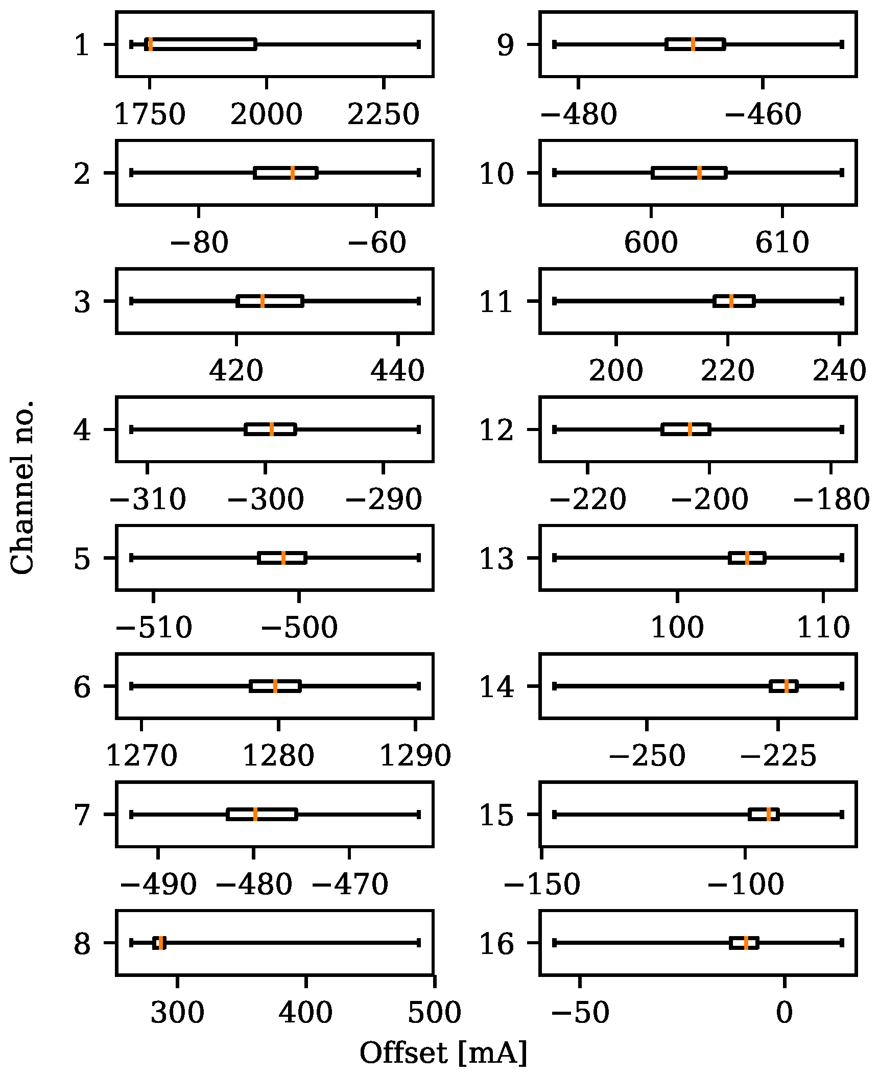
Figure 2 is a box-and-whiskers plot illustrating the current offset and its variance during 168 h of data. The 168 h offset test was carried out with no cells, meaning that the current measured through the shunt resistor was zero A. As it can be seen in
Figure 2, different offsets, some of them with hundreds of mA and considerable variances, were recorded for the several channels.
Without compensation for this error, the current measurement would jeopardize the state of charge control and subsequently all the characterization studies. For this reason, an hourly offset measurement was implemented which automatically compensated for this error.
The maximum error of the current measurement was estimated by comparing the setup’s current measurement with a reference ammeter. The reference ammeter had a specified error of up to currents up to 10 A (its maximum rated current). The largest deviation between the two measurements was 50 mA, which means that the maximum error of the setup’s current measurement is 50 mA plus the maximum error of the reference (0.01 × 10 A which is equal to 100 mA), i.e., 150 mA out of the 10 A which is ±1.5%.
Considering that each pair of voltage/current must be measured simultaneously, and the setup has 16 channels, the PXIe-6124’s four channels are insufficient for measuring the 32 measurements simultaneously. For this reason, a multiplexer using IM06 relays from TE connectivity (TE connectivity, Schaffhausen, Switzerland) was designed. The multiplexer has 32 channels which are commanded in pairs (i.e., 16 voltage/current pairs, each pair corresponding to a single cell). They are controlled by 16 of the 24 digital input/output ports also available in the PXIe-6124. The multiplexer is programmed to connect two cells (four multiplexer channels) every second to the four differential PXIe-6124 channels in a loop. Only channels which are active are muxed, i.e., if only six cells on three channels are cycling, the other channels are ignored. Hence, the maximum measurement time error introduced by the setup is eight seconds.
The temperature was measured using resistance thermometers (PT100/RTDs, from Innovative Sensor Technology IST AG, Ebnat-Kappel, Switzerland), model number P0K1.202.3FW.B.007. At 25 °C, their error is ±0.425 °C. They were used in 2-wire fashion where a reference current of 900 A was supplied by a PXIe-4357 data acquisition card from NI. Each cell temperature was measured by a PT100 sensor affixed to either the positive or the negative pole. This location was chosen for temperature measurement because each pole is threaded, allowing for secure fixation of the PT100.
2.3. Safety System
LIBs contain lithiated graphite and flammable solvents. If operated outside of specific safety margins they can undergo rapid exothermic activity and runaway reactions [
28]. Thermal runaway can subsequently lead to disastrous scenarios, such as explosions [
29] and toxic gas releases [
30]. The setup must reliably run continuously for long periods (months) and handle by itself any safety situations which may occur. To increase the setup’s operational availability, distinct safety actions, depending on detected symptoms were implemented. The safety actions were divided in two categories: alarm (constituted by actions 1, 2 and 4) and warning (constituted by actions 3 and 4) were the actions correspond to the following list:
Trigger evacuation signs, i.e., siren and emergency light
Disable all DCG and CRG
Disable (DCG’s or CRG’s) power sources linked to endangered cells
Alert the operator (on call) via email and GSM message
Fuse blows
It is assumed that an alarm can never happen without a previous warning, and with this reasoning, a set of automatic actions in reply to detected symptoms were defined.
Table 2 gathers the experimental setup safety structure.
The aspects covered in
Table 2 are accomplished by two independent hardware devices, i.e., the PXIe safety system and a safety card specially designed for this setup. The goal is to ensure redundancy between these two devices. The connection between the PXIe safety system, the safety card, and the cells is illustrated in
Figure 1.
2.3.1. PXIe Safety System
The PXIe safety system was implemented in Labview and via the PXIe-6124 card an operator can command the safety card, which is the actuator of all the automatic safety actions. For instance, if the power of the PXIe shuts down, all the digital commands sent to the safety card will be set to low, which will be interpreted by the safety card as a turn off command for the DCGs and CRGs. The PXIe is also responsible for safety functionalities, namely the heartbeat and the operator’s sanity check.
Hearthbeat
As any kind of computer, the PXIe can freeze due to software errors such as infinite loops. For such scenarios, the PXIe safety system cannot be trusted anymore, since the cell data cannot be properly processed anymore. To solve this dangerous situation, a PXIe heartbeat was created. It is a digital clock beat which is continuously sent to the safety card. This communication is carried out every second, which corresponds to the time involved in the PXIe safety verification loop.
Sanity Check
To prevent human operational errors, all the setup’s safety values are software locked. For instance, if by mistake the operator inputs cycling voltage values higher than the safety ones, that will simply not work. Sanity check functionality also takes into account the hardware, i.e., CRG and DCG limitations, so that they operate within safety margins.
2.3.2. Safety Card
The safety card is designed to supervise the DCGs and CRGs and to disable them in case of unsafe contingencies. The four DCGs are enabled/disabled by means of on-off digital signals, transmitted by the four 24 V relays available on this card. Also, when the CRGs are connected to the programmable power supplies, the same operation can be done using global standard commands for programmable instruments (SCPI) transmitted by an ethernet port. In addition, the safety card controls a GSM antenna used for sending text messages to the designated operator on call. Also, the safety card controls evacuation signals, i.e., the siren and emergency light. The safety card has two main surveillance activities: checking the climate chamber temperature and acknowledging the heartbeat of the PXIe safety system. The software of the safety card reflects
Table 2 and it is implemented using C programming language on a microcontroller. The safety card is powered by a 24 V power supply in parallel with two lead-acid batteries with a capacity of hundreds of Ah. This means that in case of an energy failure, the safety card will be able to continue operating for a very long time.
3. Experimental Setup in Operation
For the purpose of demonstrating the experimental setup in the different operation modes, commercial LIB cells with 28 Ah are tested at their BOL. The LIB’s cell positive electrodes were made of LiNi1/3Mn1/3Co1/3O2 (NMC), while the negative electrodes were graphite. The electrolyte was a dimethyl carbonate/ethyl-methyl carbonate/diethyl carbonate/ethylene carbonate (DMC/EMC/DEC/EC) mixture with lithium hexafluorophosphate (LiPF6) salt.
3.1. State of Charge Control
To follow the progress of capacity loss over time, one should define the concept of capacity so the state of charge (SOC) cycle is precisely controlled. The cell’s full capacity is the amount of charge extracted from a 100% SOC (defined at a specific voltage) all the way down to 0% (also defined at a specific voltage). However, besides of defining upper and lower voltages, also a specific current has to be defined in order to properly assess capacity. This is due to the fact that the higher the current, the more losses will occur. Subsequently, the higher the losses, the lower the cell voltage will be during discharge (and vice versa during charge).
The SOC control was implemented using the following method: the cells are charged with constant current until their voltage exceeds a specified voltage, for instance 4.1 V. When the upper voltage limit is reached, the charging changes from galvanostatic (constant current) to potentiostatic (constant voltage). The constant voltage charging is achieved simply by decreasing the current by 20% every time the upper voltage limit is exceeded. This continues until the current falls below 10% of its initial value. This charging pattern is known as the constant current constant voltage charging (CC-CV) method. At this point the cell is considered to be fully charged, i.e., SOC 100% and the discharge of the cell starts. Then, the cells are discharged with a constant current (CC) until their voltage hits a specified value, for instance 3.0 V. At this voltage the cells are considered fully discharged, i.e., 0% SOC. Unlike during charge, no constant voltage mode is used at the end of discharge.
3.2. Capacity and Energy Efficiency Characterizations
LIB cells commonly have Columbic efficiencies above 99.9% [
31], and therefore cell capacity may be defined as
where
is the discharge starting time at 100% SOC, and
is the time needed for the cell to reach 0% SOC. For the case that
is exactly one hour, then capacity may be addressed as C-rate. However, in this paper, capacity and energy efficiency characterizations are not normalized for one hour time base. In practice, the capacity may be calculated simply by multiplying the averaged discharged current by the total discharge time. For this reason, the capacity error may be calculated considering the propagation of the current and time errors a
where
is the absolute error of the current measurement,
I is the averaged discharged current,
is the absolute error for the time measurement.
Contrary to capacity, the definition of energy must consider losses and should be expressed in terms of charge and discharge. It can be expressed as
where the subscripts “c” and “d” indicate charge and discharge, respectively
is the charging starting time at 0% SOC, and
is the time needed for the cell to reach 100% SOC. Unlike capacity, energy cannot be computed simply by multiplying an averaged current by an averaged voltage and a total time. Instead, because the power is integrated to obtain the energy using the trapezoidal rule [
32], the error associated with Equations (
3) and (
4) should be expressed accordingly as
where
,
, and
and
are the total number of samples acquired in the discharge and charge periods respectively.
Finally, the cell’s energy efficiency
is found by accounting for the energy balance of a full cycle with respect to the cell’s input energy. It can be expressed as
where the losses correspond to
. Similarly, the error associated with the energy efficiency may be expressed with the propagation of
’s quantities as
For a concrete idea of the experimental setup performance with regards to above mentioned errors, a full cycle as described in
Section 3.2 was carried out to a LIB cell at its BOL. By measuring the
and applying the instrument errors of the experimental setup covered in
Section 2.2, the results of the setup measurement errors for the 28 Ah cells may be summarized in
Table 3.
3.3. Hybrid Pulse Power Current
A hybrid pulse power characterization test (HPPC) is used to characterize the power capability and, specifically, to obtain the equivalent dc resistance of a cell [
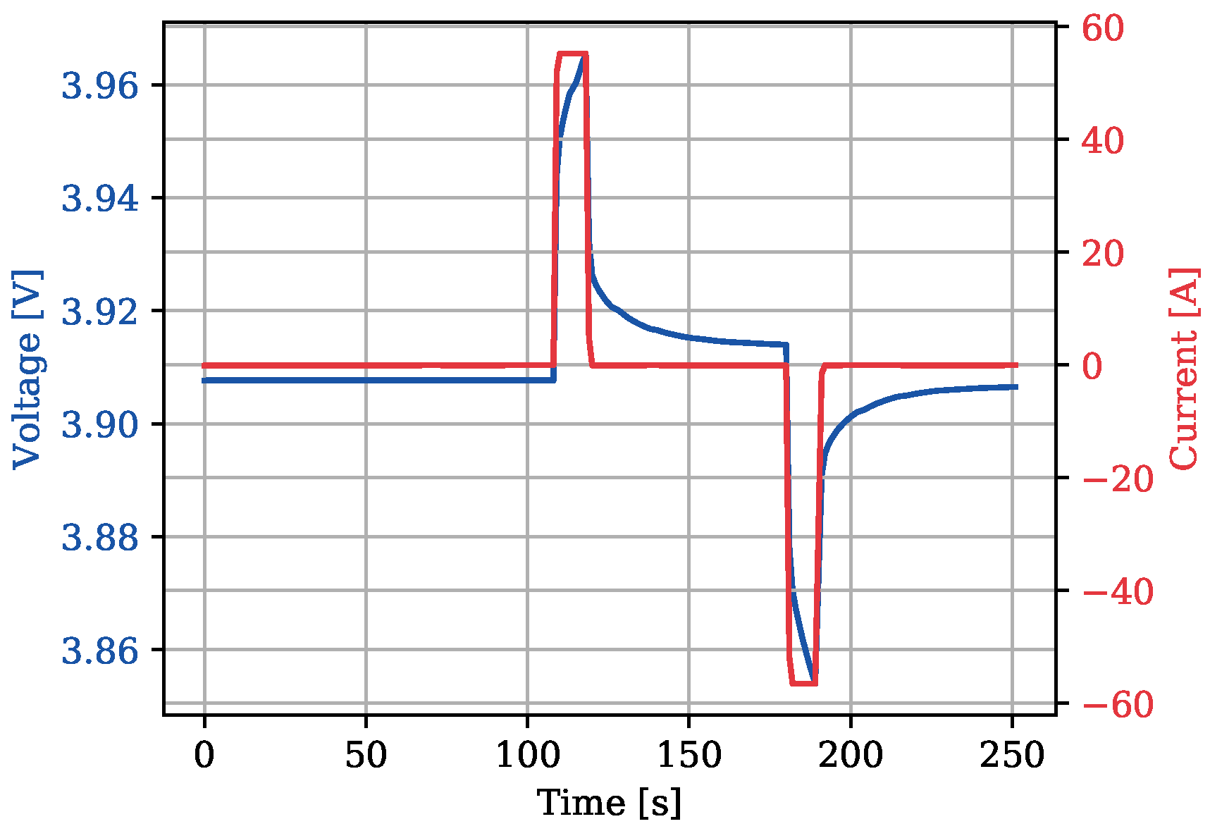
33]. In this operating mode, a large dc current (for the selected case corresponding to 2 C-rate, i.e., 56 A) is injected during two ten-second pulses separated by one minute rest before, between, and after the pulses. The first pulse has positive current while the second pulse is negative. The charging and discharging equivalent dc resistances (here called
and
) are then defined by the ratio between the pulsed voltage (here called
and
) and the measured current (here called
and
) after one or ten seconds from the pulse start. For demonstrating the HPPC test, one second data is chosen. Hence,
and
may be expressed as
Figure 3 shows the HPPC test carried out at 90% SOC.
Considering the data collected in the HPPC test, as well as the setup measurement precisions, one may calculate and as 0.779 m ± 12.01 and 0.762 m ± 11.73 respectively.
3.4. Incremental Capacity Analysis
The ICA test provides a more detailed aging signature of LIB cells and may be used to separate and understand anode and cathode aging properties [
34,
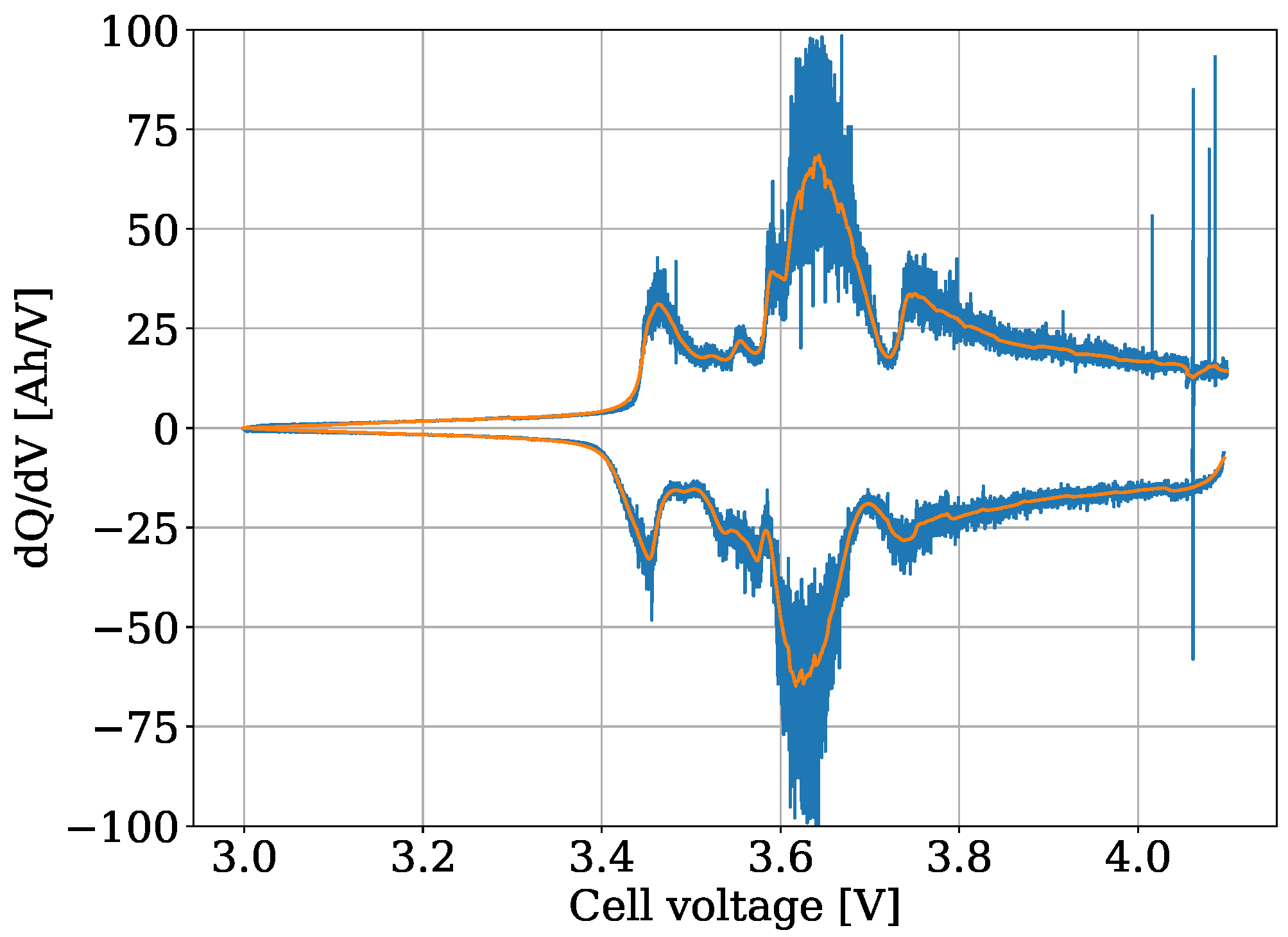
35]. To accomplish this test, a cell is cycled between two voltage limits at a very low constant current, and the capacity/voltage differential is calculated. For the test shown in
Figure 4, a current of C/20, i.e., 1.4 A was used. Some LIB testers are incapable of ICA because of the high noise-sensitivity in the flat voltage regions of the I-V LIB profile [
35]. However, it is possible to instead adopt incremental voltage analysis, in which the voltage differential is used instead of the capacity differential. These methods provide equivalent information.
Figure 4 shows an ICA test where, for pedagogical reasons, the unfiltered data is also shown.
ICA must be done with very low current for the peaks to appear clearly, but the low current also means that the technique is noise-sensitive. For example, say that the voltage increases by 1 mV between two data points, and then by 2 mV by the next two data points. Assuming that current and sample rate are constant, the differential will then be twice as large between the first two points as between the second pair. Most likely, this does not reflect reality, but merely a limitation in the instrument’s voltage resolution.
In addition, the specific equipment detailed in this work had another major source of noise in the measurement: the hourly current offset calibration which has been mentioned previously. Although the setup was only shut off for calibration for approximately ten seconds per hour, that small amount of time was enough for the cells under test to relax toward equilibrium ever so slightly. When the setup came back online, the voltage difference between each sample was momentarily much higher than normal as the cell returned to a polarized state. Fortunately, since this particular source of noise had a known frequency of 1/3600 Hz it was easy to filter out in post-processing of the data.
3.5. Galvanostatic Intermittent Titration Technique
For the measurement of the open cell voltage and voltage relaxation, GITT may be used [
36]. In this operating mode, the cell is cycled using long pulses (by default two minutes) of dc (for the test shown in
Figure 5 at 1C-rate, i.e., 28 A), followed by long periods of zero current (set to 30 min).
Figure 5 shows a GITT test where the relaxation voltage is in blue and in orange one can observe an approximation of the cell’s open voltage throughout a full cycle.
Other than the open circuit voltage, information about the diffusion coefficients of lithium ions through the electrolyte and electrodes can be acquired from GITT, as well as the exchange current density at either electrode. The exchange current density is related to the rate of reaction of the dynamic equilibriums at the electrodes when the cell is at rest. In order to get this information, it is necessary to fit the GITT data to a physics-based model such as the Newman model [
37].
4. Preliminary Capacity Fade Measurements
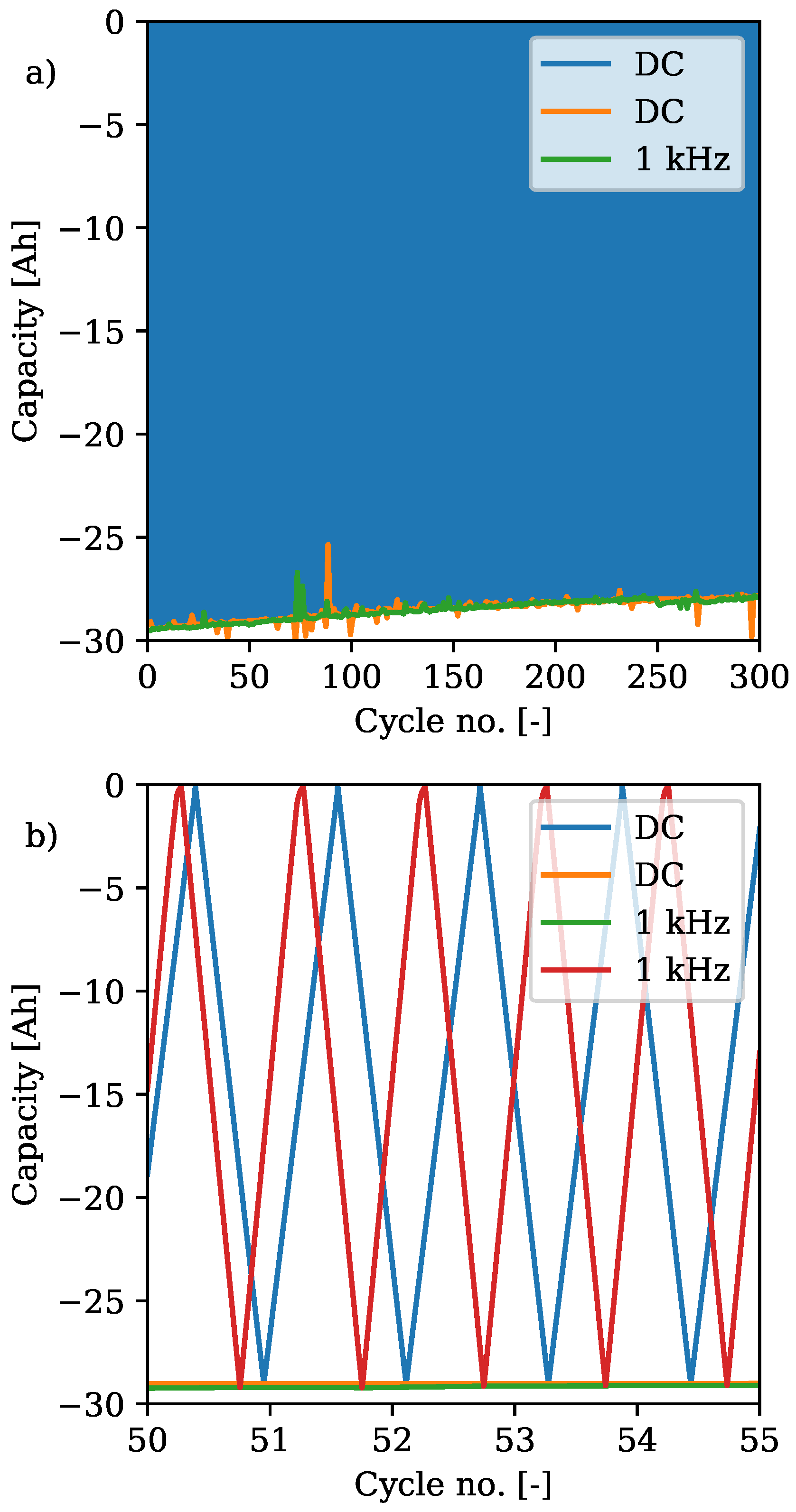
Capacity fade is an indicator of aging in LIBs and may be used to test LIB performance under different charging/discharging conditions. Specifically, capacity fade may be a figure of merit to identify the impact of ac currents in LIB cells. For this purpose, two 28 Ah LIB cells were cycled between 0 to 100% SOC with 28 A dc current and in a 40 °C controlled environment. One cell was cycled with dc current only, while the other was cycled with 21 A ac current alternating at 1 kHz superimposed to the dc current.
Figure 6 shows the cell capacity of the above mentioned test, where the cell capacity was calculated using Equation (
1). Typically capacity fade is quantified by the decrease of the peak capacity, green and orange traces found on
Figure 6, which for the dc cycled cell was 1.52 Ah, and for the dc cycled with superimposed ac current was 1.56 Ah. Considering that the capacity of the cells at BOL was 29.35 Ah and 29.39 Ah respectively, this means that the dc cycled cell lost 5.2% of its capacity, while the cell cycled with super imposed ac current lost 5.3% of its capacity. Hence, these data show a similar capacity fade in both cells after 300 cycles. Nonetheless, capacity fade tests are long term tests and require statistical significance.
Figure 6 its a preliminary test, where only around 5% of capacity faded, and with only in two cells. Therefore no conclusion may be withdrawn yet. This activity is planned for future publications, where detailed results of the LIB cell’s capacity fade cycled thousands of times for different ac current scenarios, together with results of periodical HPPC, ICA, and EIS tests will be published.
5. Conclusions and Future Work
In this paper, an experimental setup with alternating current capability for evaluating large LIB cells was presented. The experimental setup showed marginal measurement errors at its incorporated LIB cell characterization routines, namely, cell capacity, cell charge and discharge energies, cell efficiency, HPPC, ICA, and GITT.
Twenty-eight-Ah NMC LIB cells are currently being cycled with and without the injection of 21 A alternating at 1 kHz. From BOL up to 300 cycles, no significant cell capacity fade could be detected between the tested cells, meaning that alternating currents may not have the harmful impact in LIB as commonly assumed by the LIB manufactures. Upcoming publications will analyse in detail the data resulting of different tests operating the presented experimental setup.
As an improvement, an in-built EIS functionality per channel may be an interesting up-grade, since it would allow online EIS measuring which would improve operationality.
