1. Introduction
Olivine-type cathodes, such as LiXPO
4 [X = iron (Fe), manganese (Mn), cobalt (Co), and nickel (Ni)], have gained importance since the introduction of phospho-olivines for lithium-ion batteries by Goodenough [
1]. Lithium iron phosphate (LiFePO
4; LFP) has been most widely adopted despite a lower energy density (
E) of ~160 Wh kg
−1 than nickel manganese cobalt oxide or nickel cobalt aluminum oxide (210–250 Wh kg
−1) [
2,
3]. LFP is cheaper, safer, and more sustainable and offers a longer cycle life (~2500 vs. 1000 cycles) than other similar oxides [
4,
5]. Its thermal stability, ascribed to strong P–O bonds, reduces the risks of overheating, gas release, and thermal runaway. Thus, it enables the fabrication of simple and low-cost systems without extensive monitoring or cooling [
6,
7]. It has been commercialized and widely used in electric vehicles (EVs). Despite the superior safety and sustainability of LFP, its low gravimetric energy density limits the EV driving range [
8]. New compounds need to be explored to meet the 2030 target of high energy density (500 Wh kg
−1), which is ~60% higher than that of the present cells [
9]. Lithium manganese phosphate (LiMnPO
4; LMP) exhibits ~0.4 V higher potential than LFP, while lithium manganese iron phosphate (LiMn
xFe
1−xPO
4; LMFP) improves the poor conductivity and voltage of LMP and LFP, respectively. LMFP achieves ~210 Wh kg
−1 for a cell, ~15% more than LFP [
10,
11].
Mn doping in LMFP/C substantially enhances the electrochemical performance of LFP. Incorporating Mn into the LFP structure increases the Li-ion diffusion coefficient (D
li) by nearly two orders of magnitude, maintaining stable cycling performance [
12]. Even slight doping of Mn (x = 0.03) can enhance the unit cell volume and accelerate Li-ion diffusion, improving cycle stability [
13]. An increase in the Mn content in Mn-substituted samples (x = 0–0.3) exhibited small particle sizes and slightly expanded lattice parameters, which facilitated Li-ion mobility [
14]. Mn–O bonds are shorter than Fe–O bonds, causing minor changes in lattice constants. These distortions cause local expansion of the orthorhombic lattice, influencing the pathways available for Li
+ diffusion [
15]. While Mn doping slightly reduces the charge–discharge capacity of the LFP structure, its overall impact on the energy density of the material remains acceptable owing to the presence of an extra plateau of MnPO
4–LiMnPO
4 phase transformation in addition to the FePO
4–LiFePO
4 plateau in charge–discharge plots [
16]. The high voltage of the additional plateau remarkably improves energy density and attracts the attention of EV manufacturers.
Despite considerable advancements, LMFP materials still suffer from notable challenges, including poor electronic conductivity, slow Li-ion diffusion, Mn dissolution that undermines cycling stability, and low tap density. Extensive research has focused on overcoming these challenges by designing multimetallic olivine cathodes using magnesium (Mg), titanium (Ti), or other dopants to synergistically enhance conductivity, stabilize the structure, and minimize degradation [
17]. Metal cation doping enhances ionic diffusivity and conductivity via structural defects and enhanced diffusion channels. Calcium ion (Ca
2+) doping at the Fe site (via calcium sulfate in the precursor solution) eliminated Fe antisite defects thanks to enhanced nucleation and particle growth restriction at the nanoscale. Calcium facilitated the surface aggregation of Fe defects, which were then more easily removed during calcination. Ca doping prevented Fe from occupying Li sites (M1 sites) in the olivine lattice, thereby preserving open Li
+ diffusion pathways and resulting in improved electrochemical performance [
18]. Mg doping at the Mn/Fe site resulted in a high-performance LMFP structure. Reportedly, the addition of 0.02% Mg to the LFP structure, as a LiMg
0.02Fe
0.98PO
4 structure, delivered a lower discharge capacity (
DC) of 142 mAh g
−1 at 0.1 C (compared with the practically reported capacities of LFP, i.e., 160 mAh g
−1, in the literature). However, it provided remarkable rate capability at a high 2 C rate (120 mAh g
−1) and long-term cycling stability (94.5% capacity retention after 150 cycles). Therefore, Mg substitution enhanced structural stability and Li
+ transport and, consequently, improved the overall capacity, rate performance, and durability [
19,
20]. Doping LFP via a small amount of Mg
2+ (approximately 0.2–0.6%) can enhance its rate capability and cycling stability by fine-tuning the lattice and electronic structure. In combination with carbon coating, Mg
2+ suppresses the formation of the insulating Li
3PO
4 and improves conductivity and ion transport. However, because Mg
2+ is electrochemically inactive, excessive doping decreases the overall performance [
21]. Therefore, an optimal level of any dopant, such as Mn
2+, Mg
2+, or other related cations, might help to stabilize the crystal structure and enhance cycling stability.
Herein, we extend this dopant-optimization philosophy to Mn–Fe mixed olivine systems. We systematically explored Fe substitution levels in LiMnxFe1−xPO4, characterized their structural and morphological changes, and evaluated the electrochemical kinetics [plateau behavior and differential capacity (dQ/dV)] and cycling stability to determine an optimal composition. Mg doping was analyzed to investigate the possibility of achieving LMFP with good performance and doping mechanisms. We determined (i) whether Mg and Mn or their combinations inherently enhanced the performance, or (ii) if a specific optimal level and combination are required. Morphological evolutions, lattice distortions, and electrochemical properties related to controlled doping were investigated to obtain high energy and power density in olivine cathodes.
3. Results and Discussion
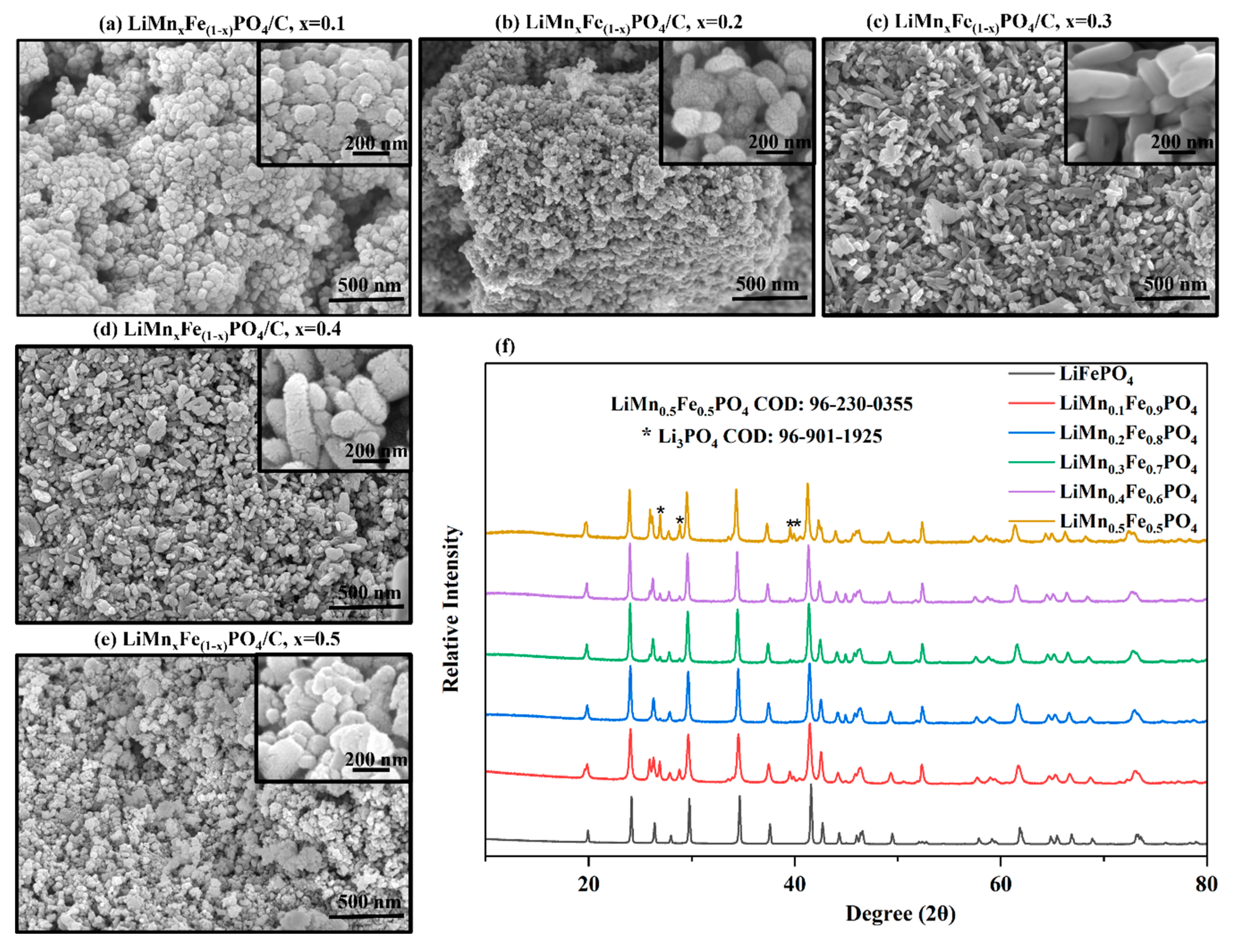
The FESEM and XRD results (
Figure 1) reveal a correlation between the substituted Mn content and the resulting morphology and structural characteristics of LMFP samples. At low Mn contents (x = 0.1–0.2;
Figure 1a,b), the particles exhibit a round-shaped morphology, while increasing the Mn content (x = 0.3) produces well-defined solid rod-like structures with optimized growth along the b-axis. The particles are relatively homogeneous in shape and size, whereas these rods are rigid and compact. However, when the Mn content is >0.3, the morphology alters to porous rods (x = 0.4) and less uniform and irregular shapes (x = 0.5), indicating structural distortion owing to excessive Mn incorporation. The morphology appears denser and highly compact in LiMn
0.3Fe
0.7PO
4, with improved particle connectivity and reduced interparticle gaps. Such nanoscale uniformity is beneficial for enhancing Li
+ diffusion and electronic conductivity. The addition of Mn to LFP enhances the porous structures in the final product [
14]. The XRD results further support this observation, showing that all the samples retain the olivine
Pnma structure of LFP. However, the peaks shift as Mn replaces Fe. LiMn
0.2Fe
0.8PO
4 displays the highest purity and best phase homogeneity after Mn addition. However, LiMn
0.3Fe
0.7PO
4 exhibits the highest structural integrity, as indicated by the FESEM micrograph (
Figure 1c), with negligible Li
3PO
4 impurity. Peaks shifting toward smaller angles confirm lattice expansion owing to Mn incorporation.
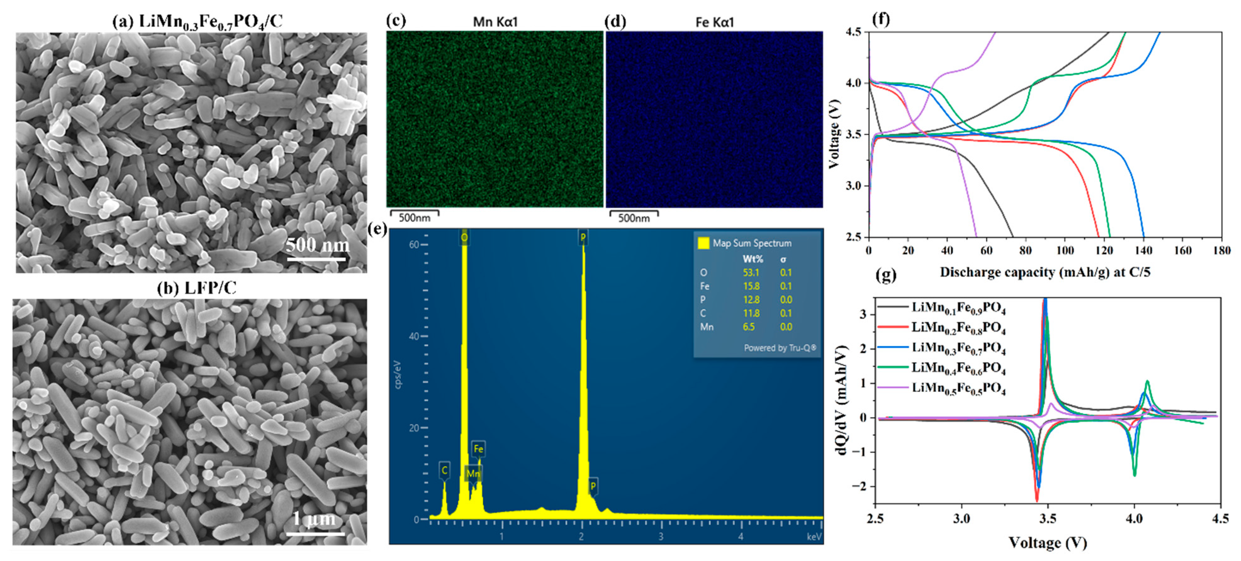
We compared the FESEM micrographs of LiMn
0.3Fe
0.7PO
4/C with our synthesized reference LFP/C sample (
Figure 2a,b). LMFP exhibits the highest morphological similarity to LFP. Among all the LMFP samples (
Figure 1), LiMn
0.3Fe
0.7PO
4/C exhibits a rod-shaped morphology, similar to LFP. However, small rods (<500 nm long) indicate that Mn incorporation during synthesis effectively limits grain growth and promotes uniform nucleation. LFP/C exhibits large particles (up to ~1 µm size). The rod-like particles in LFP/C and LiMn
0.3Fe
0.7PO
4/C are compact and exhibit high structural uniformity. The rod-shaped morphology of LFP deviates upon the addition of a low Mn content (x = 0.1;
Figure 1a), enhancing nucleation by its slightly larger ionic radius. This introduces lattice distortion and increases surface energy. This high surface energy favors the formation of numerous small nuclei toward fine, round, and agglomerated particles rather than well-grown rods of pure LFP (
Figure 2b). This deteriorates structural uniformity and particle integrity owing to low Mn substitution [
23]. As the Mn content increases to moderate levels (x = 0.3), the system establishes a good balance between nucleation and crystal growth, inducing anisotropic crystal growth along the [010] direction and rod reformation. However, with a high Mn content (x > 0.3), the lattice strain and mismatch between Fe–O and Mn–O bond lengths significantly increase and disturb the diffusion-controlled growth process. This results in nonuniform crystal growth, particle coalescence, and the formation of large irregular grains. Excessive Mn tends to destabilize the preferred (010) growth plane of LFP toward multidirectional growth and morphological irregularities.
The energy-dispersive spectroscopy (EDS) elemental mapping and spectral analysis results (
Figure 2c–e) demonstrate the uniform dispersion of Mn within the LFP olivine structure to form a homogeneous solid solution. The elemental maps demonstrate that, in addition to intrinsic LFP components (Fe, P, and O), Mn and C are evenly distributed in the composites. The EDS analysis results confirm the successful incorporation of Mn into the LFP lattice by revealing a close match of the atomic ratios with the intended substitution level (Fe = 15.8 wt.% and Mn = 6.5 wt.%;
Figure 2e). However, the amount of C must be justified as only ~2 wt.% originates from the calcination process, with the remainder attributed to the C substrate. Correcting C and recalculating yields an Fe:Mn weight ratio of 2.43 or an atomic ratio of 2.39, which is in good agreement with the theoretical value of LiMn
0.3Fe
0.7PO
4 (Fe:Mn = 0.7/0.3 = 2.33). This consistency confirms that the Mn doping level is well controlled and aligns with the designed stoichiometry.
The electrochemical characterization (
Figure 2f,g) provides further insight into the effect of Mn substitution on the
DC, redox behavior, and cycling stability of Mn-doped LFP.
Figure 2g shows that Mn addition of x = 0.3 increases the
DC of LMFP, while it decreases for samples with higher Mn content (x > 0.3). The charge–discharge curves (
Figure 2g) exhibit two main voltage plateaus at ~3.5 and ~4.1 V for the Fe
2+/Fe
3+ and Mn
2+/Mn
3+ redox couples, respectively. The Mn
2+/Mn
3+ plateau is not visible in samples with less Mn content (x = 0.1) as the Mn reaction cannot be recognized. As the Mn content increases, this plateau becomes highly pronounced with increased Mn participation in the redox reaction. However, at high Mn content (x ≥ 0.4), the overall
DC decreases because of (i) poor conductivity and structural distortion induced via excessive Mn doping and (ii) high porosity (observed from FESEM micrographs) or impurity content [indicated by XRD results,
Figure 1f]. Li
3PO
4 impurity is electrochemically inactive and reduces the amount of active material. Although the
DC of LiMn
0.3Fe
0.7PO
4/C is higher than that of the other samples, it is lower than that obtained for pure LFP/C (
Figure 2g), which agrees with the reported results in the literature [
13], where moderate Mn addition lowers discharge capacity in Mn-doped LiFePO
4/C. The cyclability and rate performance of the synthesized LFP/C are provided in our previously published work [
24].
Excessive Mn incorporation results in lattice distortion, high internal resistance, and low–rate capacity. Mn doping mainly reduces polarization under fast cycling, but it does not enhance electronic or ionic conductivity. However, it distorts the crystal structure and decreases overall
DC [
21]. Mn doping in LiFePO
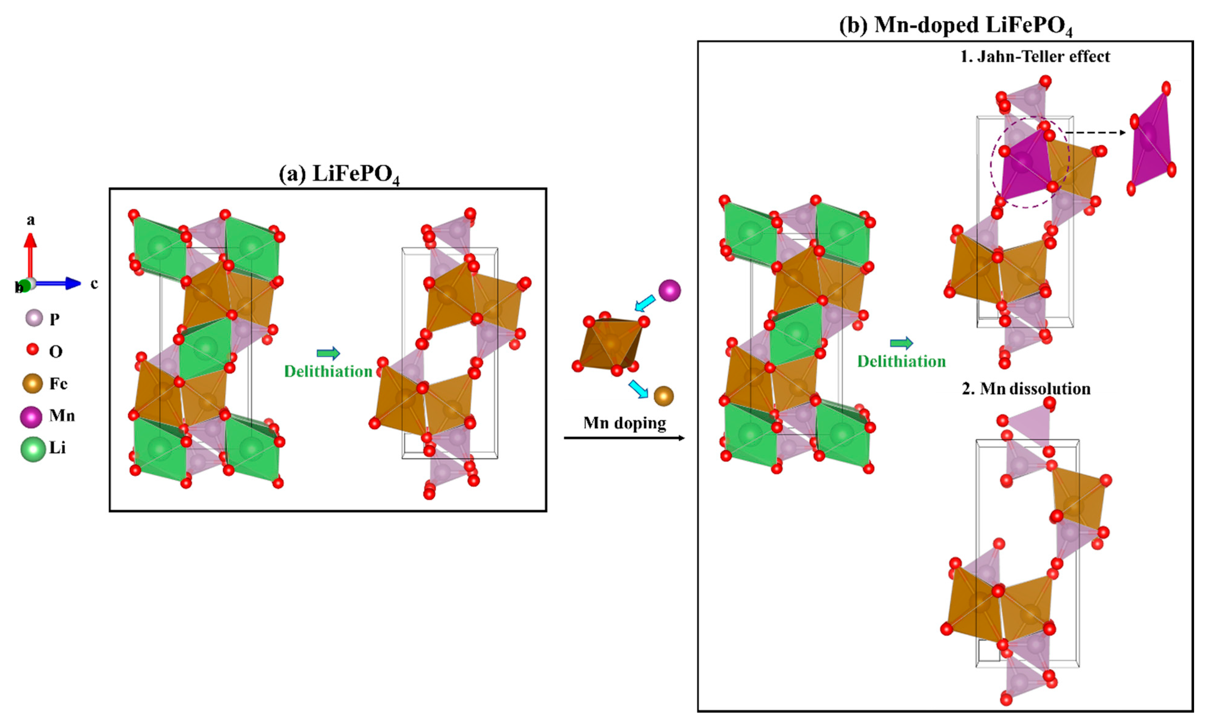
4 introduces lattice distortion and stability issues based on the Jahn–Teller effect [
25,
26] and Mn
3+ dissolution [
27], whereas it does not occur in LFP during charging delithiation (
Figure 3a). Based on the inductively coupled plasma (ICP) results [
28], dissolved transition metal ions can migrate through the electrolyte and deposit on the lithium metal anode, leading to solid electrolyte interphase (SEI) thickening. When Fe
2+ is partially replaced by Mn
2+, the unit cell expands. Upon delithiation (
Figure 3b), Mn
2+ oxidizes to Jahn–Teller-based active Mn
3+ (d
4). Consequently, asymmetric Mn–O bond elongation and compression distort the MnO
6 octahedron, weaken the FeO
6–PO
4–MnO
6 network, and increase the local strain. High Mn content (x ≥ 0.4) and distortion reduce conductivity and trigger Mn
3+ decomposition (2Mn
3+ → Mn
2+ + Mn
4+). Mn
2+ dissolves into the electrolyte, while Mn
4+ remains inactive. Together, they degrade the cathode–electrolyte interface [
27]. Moderate Mn levels (x ≤ 0.3) balance between lattice expansion and stability, while excessive Mn leads to severe distortion, dissolution, and capacity fading.
dQ/dV plots (
Figure 2g) reveal well-separated redox peaks for Fe
2+/Fe
3+ and Mn
2+/Mn
3+ couples. The LiMn
0.3Fe
0.7PO
4/C peaks are the sharpest and most symmetric, indicating improved electrochemical reversibility and low polarization at this composition based on morphological and crystallographic changes. Thus, an x value of 0.3 yields the optimal structure and charge-transfer pathways. In the cycling performance, LiMn
0.3Fe
0.7PO
4/C exhibits the highest
DC and best capacity retention among all the Mn-substituted samples (97%). Increasing the Mn content to 0.3 enhances
DC, while higher Mn content (x > 0.3) causes capacity fading.
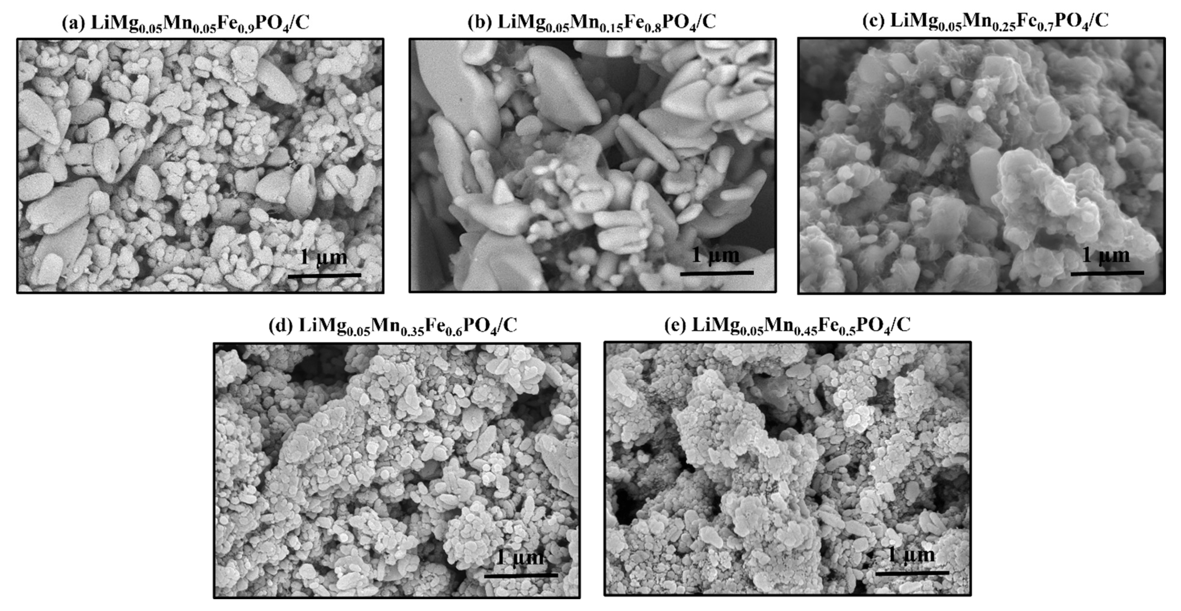
The FESEM micrographs (
Figure 4) for the Mn–Mg-codoped samples reveal morphological evolution in LiMg
0.05Mn
xFe
1-xPO
4/C with increasing substituted Mn content. At a low Mn content (x < 0.2;
Figure 4a and
Figure 5b), the particles preserve the rod-like morphology of olivine LFP (
Figure 2b). This anisotropic crystal growth along the c-axis, perpendicular to the [010] direction, maintains the short Li
+ diffusion channel. The preserved LFP morphology codoped with less Mn–Mg content (compared with the Mn-doped samples in
Figure 1a,b) suggests that limited Mn and Mg doping does not strongly disrupt the Fe–O–P framework. Mn
2+ enhances surface energy and the nucleation rate even when codoped with less Mn content. Mg
2+ substitution acts as a surface modifier, which lowers surface energy and promotes grain growth. Surface energy is lowered owing to the shrinkage of the crystal lattice, with small Mg ions replacing the large Fe ions [
29].
Figure 1 and
Figure 4 show that the morphological transition from rod-like structures to spherical and agglomerated structures with increasing Mn content (regardless of Mg doping) is governed by the interplay of surface energy, lattice strain, and dopant-induced nucleation behavior. Moderate Mn levels (
Figure 4c) balance nucleation and growth and produce small but well-crystallized particles. In contrast, high Mn levels (
Figure 4d,e) destabilize the olivine lattice and promote irregular aggregation. Mg doping hinders this phenomenon as additional elongated particles are formed in low Mn-doped ratios in Mg-doped LFPs (
Figure 4a,b).
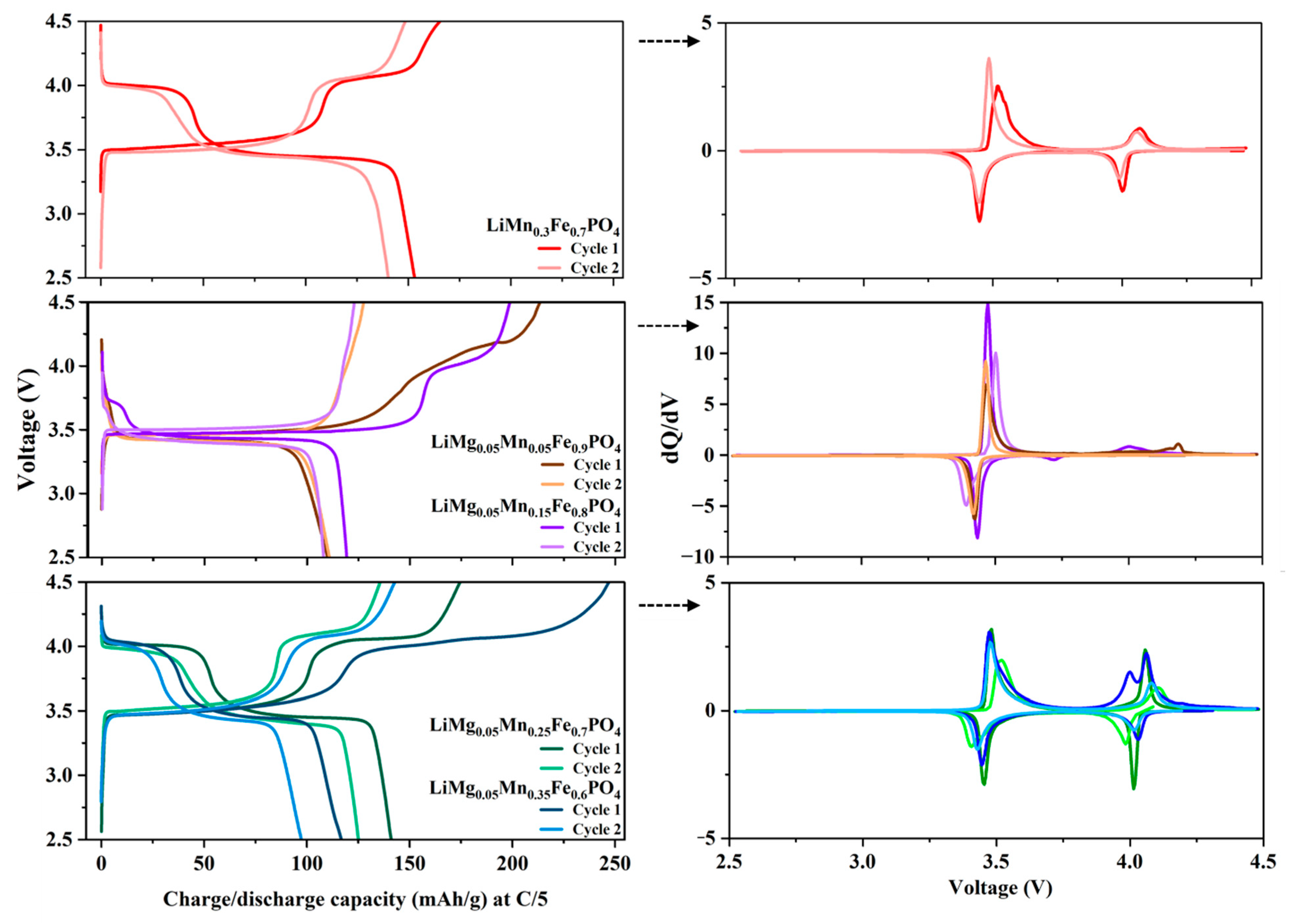
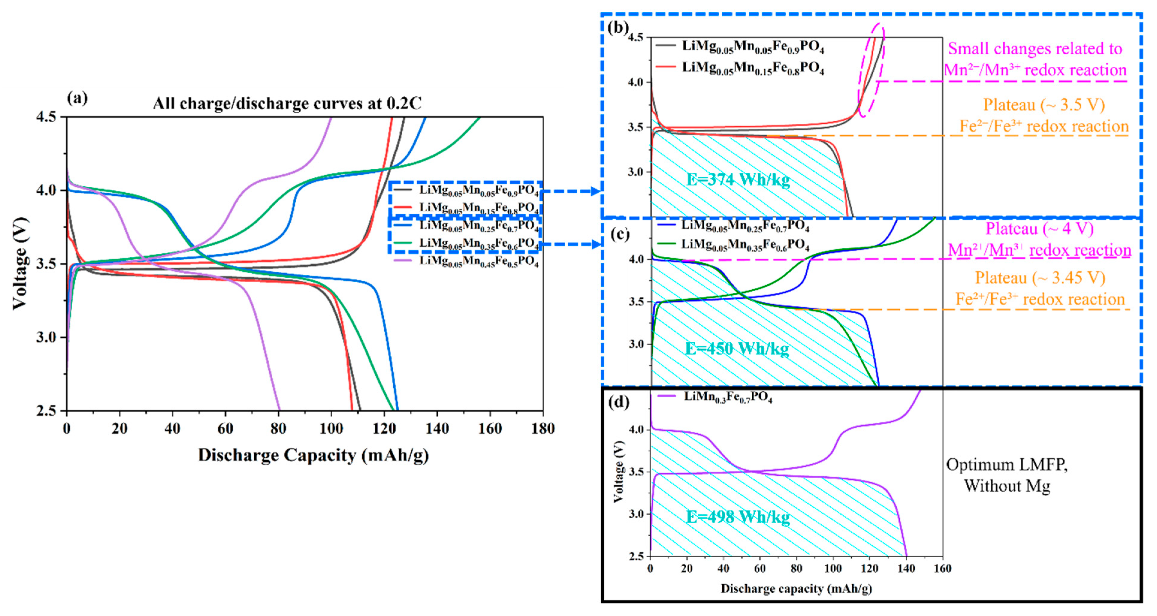
The charge–discharge voltage profiles of the Mg–Mn-codoped LFP samples (
Figure 5a) reveal the influence of the composition on electrochemical performance. The discharge capacities increase with Mn content in LiMg
0.05Mn
xFe
1-xPO
4 up to the x value of 0.25 and then decrease. For LiMg
0.05Mn
0.05Fe
0.9PO
4 and LiMg
0.05Mn
0.15Fe
0.8PO
4 (
Figure 5b), two low-Mn-content samples, the voltage curves exhibit relatively similar electrochemical behavior to LFP, with well-defined plateaus that are characteristic of the two-phase Fe
2+/Fe
3+ redox reaction with moderate capacities (~100–110 mAh g
−1). In contrast, high Mn substitution in LiMg
0.05Mn
0.25Fe
0.7PO
4 and LiMg
0.05Mn
0.35Fe
0.6PO
4 (
Figure 5c) increases discharge capacities up to 125 mAh g
−1, indicating a greater involvement of the Mn
2+/Mn
3+ redox couple with the Fe
2+/Fe
3+ reaction. However, the broad plateaus suggest highly complex reaction pathways and potential structural strain. Excessive Mn substitution (x > 0.25) reduces stability and
DC, which underscores the need to optimize Fe:Mn ratios for enhanced
E and cycling performance.
Incorporating Mg
2+ reduces the possibility of Li–Fe antisite defect formation while simultaneously facilitating iron phosphide (Fe
2P) generation. Although Fe
2P is considered an impurity, its formation via Mg doping benefits the conductivity and cycling performance of LFP. Fe
2P formation enhances electronic conductivity owing to the metallic nature of Fe
2P (up to 275× that of pure LFP), exhibiting superior electrochemical performance, including high discharge capacities and cycling stability (>98% Coulombic efficiency) [
30]. However, LMFP exhibits a substantial decrease in its electrochemical performance owing to Mg doping [
DC for LiMg
0.05Mn
xFe
1-xPO
4/C (
Figure 5) compared to LiMn
xFe
1-xPO
4/C (
Figure 2)]. This is more likely because Mg is electrically inactive, as confirmed by the investigation of Mg
0 energy. The Mg
0 energy is the lowest for the entire range of Fermi-level values compared to Mg
+ and Mg
2+ energy [
31].
Discharge in LFP occurs through the Fe
3+/Fe
2+ redox couple, while LMFP involves Mn
3+/Mn
2+ (high-voltage plateau) and Fe
3+/Fe
2+ (low-voltage plateau) reactions. The calculated
E of these cathodes [depending on
DC and average voltage (
V),
E =
DC ×
Vavg] is presented in
Figure 5. LMFP exhibits a higher
V and
E than LFP because of the higher Mn redox potential (~4.0 V) than that of Fe (~3.5 V). The advantage of the Mn redox plateau on
E is evident in the total area under the
DC curve. The extension of the Mn
3+/Mn
2+ plateau at the expense of the Fe
3+/Fe
2+ plateau results in a high discharge capacity. The precise values for
C,
V, and
E (material-level, based on the cathode active mass) are provided in
Figure 5b and
Figure 6. A Mn content of 25% in LiMg
0.05Mn
0.25Fe
0.7PO
4/C exhibits the highest
DC of 125 mAh g
−1 and
E of 450 Wh kg
−1, 20% more
E than LiMg
0.05Mn
0.05Fe
0.9PO
4/C and LiMg
0.05Mn
0.15Fe
0.8PO
4/C. However, the
E of the Mg-doped samples is lower than that of the Mn-doped samples, while it is 10% lower in the optimum Mg–Mn-codoped sample (LiMg
0.05Mn
0.25Fe
0.7PO
4/C) than in the optimum Mn-doped sample (LiMn
0.3Fe
0.7PO
4/C;
Figure 5d).
Figure 6 shows the effect of Mg–Mn codoping. The charge–discharge profiles reveal key redox behavior of the material. The low-voltage plateau near 3.4–3.5 V corresponds to the Fe
2+/Fe
3+ (LFP ↔ FePO
4) reaction, while the high-voltage plateau at 4.0–4.2 V originates from the Mn
2+/Mn
3+ (LiMnPO
4 ↔ MnPO
4) process. The capacity of the Mn plateau in the discharge curves of LiMg
0.05Mn
0.05Fe
0.9PO
4/C and LiMg
0.05Mn
0.15Fe
0.8PO
4/C fades from the first cycle to the secnd cycle, resulting in a massive decline in the discharge capacity. This fading capacity is caused by the release of Mn and its contribution to an irreversible reaction. The same phenomenon is reported for LiMn
0.2Fe
0.8PO
4/C [
12].
Sharp Fe and broad Mn peaks related to their redox reactions appear in dQ/dV plots (
Figure 6). The peak width indicates the kinetics of reactions, with narrow peaks for fast uniform reactions of Fe
2+/Fe
3+ and broad peaks for slow heterogeneous reactions of the sluggish Mn
2+/Mn
3+. Differences between the first and second cycles in the intensity and peak positions indicate a large irreversible charge or structural change. In Fe-rich samples, the Fe redox couple (≈3.4–3.5 V) exhibits a sharp symmetric dQ/dV peak of a two-phase reaction with good reversibility and low polarization. In contrast, the Mn redox process (≈4.0–4.2 V) reveals broad peaks with less intensity during discharge owing to slow kinetics, high polarization, and partial irreversibility under cycling conditions. A large first cycle charge capacity relative to the discharge in the Mg-doped samples compared to non-Mg LiMn
0.3Fe
0.7PO
4/C indicates irreversible Li consumption via side reactions or structural rearrangements.
After the first cycle, the available reversible Li is reduced, while the second cycle shows the stabilized reversible fraction. As the Mn content increases, the Mn-related peak area expands, with an enhanced capacity contribution. Mg codoping at low concentrations introduces local disorder that hinders Li-ion transport [
30]. The redox peaks of LiMg
0.05Mn
0.05Fe
0.9PO
4/C and LiMg
0.05Mn
0.15Fe
0.8PO
4/C at high voltages appear in the first cycle, while they disappear in the second cycle owing to various possible reasons: (i) the occurrence of irreversible side reactions owing to nonconductive phases, including those related to Mg and impurities, and (ii) another key mechanism involves Mn oxidation–induced dissolution and structural changes, which are highly pronounced with nonstable Mn–Mg-codoped small particles with high surface energy.
Figure 5a,b show two distinct sizes of doped particles produced at low Mn concentrations. The EDS point analysis results of these particles reveal that larger particles have lower Mn content, while smaller particles have higher Mn content. This is mainly owing to the slow kinetics of Mn-ion diffusion, which prevents it from diffusing into larger particles at the same rate as it diffuses into smaller particles. The Mn content in small particles is twice that in large particles. Therefore, these particles with high surface energy dissolve easily during cycling without participating in reversible reactions.
Applying a high
V of 4.5 V to LMFP oxidizes Mn to Mn
3+/Mn
4+, which dissolves in the electrolyte or promotes local structural distortions and transition-metal migration. Mn dissolves or migrates from active lattice sites and does not contribute to the redox process, diminishing the Mn peak in the second cycle, indicated by the decreased Mn-related peak intensity in the second cycle in the dQ/dV plots for all the Mg–Mn-codoped samples with various Mn contents. LiMn
0.3Fe
0.7PO
4, LiMn
0.1Fe
0.9PO
4, and LiMn
0.2Fe
0.8PO
4/C fail to exhibit this factor (
Figure 2). The Mn redox peak completely disappears in the Mg-doped samples with low Mn content (LiMg
0.05Mn
0.05Fe
0.9PO
4 and LiMg
0.05Mn
0.15Fe
0.8PO
4/C;
Figure 6). This phenomenon can be reduced by charging Mg-doped samples at a voltage of <4.5 V. Another factor is kinetic and transport limitations, where Mn redox reactions are intrinsically slower and more polarized than Fe-based redox reactions. During the first cycle, Mn oxidation might occur, but sluggish kinetics or poor electronic pathways prevent full Li reinsertion during discharge. As a result, the Mn discharge peak disappears. In a few cases, formation of inactive or conductive impurity phases might also play a role. Mn and Mg doping can promote the formation of secondary phases that alter the local chemical environment of Mn or trap Li ions, rendering parts of the Mn redox process electrochemically inactive. Careful control of temperature, reaction conditions, and lowering the Mg content can reduce this effect. The fading of the Mn redox peak is attributed to the surface, structural, and kinetic factors. Lowering the cycle rate in the first and second cycles to stabilize the Mg–Mn phases and reducing the upper cut-off voltage to prevent over-oxidation and Mn dissolution can resolve the issue.
The dQ/dV profile shows the presence of three distinct anodic peaks during the charging of LiMg
0.05Mn
0.35Fe
0.6PO
4/C and LiMg
0.05Mn
0.45Fe
0.5PO
4/C, owing to multiple redox processes and phase transitions within the electrode. The two main redox couples of Fe
2+/Fe
3+ at ~3.47 V and Mn
2+/Mn
3+ at ~4.06 V are similar to those observed for other samples. However, the presence of a third anodic peak at 4.00 V suggests highly complex electrochemical behavior. The third hump likely arises from a multiphase transition involving two slightly different Mn contents: Mn-rich and Mn-deficient domains. In contrast, the two Mn-related reduction peaks tend to merge into a single broad peak, likely due to Mn
3+ dissolution. Meanwhile, the Fe
2+/Fe
3+ couple remains unchanged. Two humps have been reported for the Mn
2+/Mn
3+ redox reaction, with two cathodic peaks for Mn
3+ reduction. The total capacity of these two peaks is consistent with the Mn
2+ charge capacity [
16].
The electrochemical properties of our synthesized cathodes were compared with those of reported cathodes (
Table 1). The results highlight the effects of Mn and Mg doping on LFP/C-based materials. Pristine LFP/C delivers high discharge capacities of ~160 mAh g
−1 at low rates (0.1 C) and retains >90% capacity after 50–300 cycles. Mn-doped LFP shows high capacity and cycling stability. LiMn
0.5Fe
0.5PO
4/C exhibits 155 mAh g
−1 (0.1 C) and maintains 98% capacity after 200 cycles [
32]. Herein, the optimized Mn-doped LiMn
0.3Fe
0.7PO
4/C demonstrates high electrochemical performance by delivering 140 mAh g
−1 capacity at 0.5 C with 97% retention after 30 cycles owing to redox reversibility. Our Mg–Mn-codoped LiMg
0.05Mn
0.25Fe
0.7PO
4/C shows inferior capacity performance (125 mAh g
−1 at 0.5 C) despite maintaining excellent stability (98.6% retention). Overall, our findings indicate that, while Mn substitution at the optimum level maintains electrochemical activity and reversibility in the LFP framework, Mg–Mn codoping does not yield high performance at the tested concentration.