Abstract
To enhance the performance of state-of-the-art lithium-ion batteries, high-capacity silicon is increasingly introduced as active material for anodes. Furthermore, advanced batteries with new electrode architectures—so-called 3D architectures—can provide significantly enhanced electrochemical performance compared to state-of-the-art batteries. To facilitate and speed up the architectural development, the laser-induced forward transfer (LIFT) process was applied as a digital additive manufacturing method. As polyvinylidene fluoride (PVDF), the binder commonly used in the LIFT process, is not a suitable binder for silicon-containing electrodes due to its weak binding forces, polyacrylic acid (PAA) was introduced as a binder for use in printable electrode pastes. Since water as a solvent in such pastes evaporates quickly and the corresponding printing time would be too short, glycerol was added to the solvent mixture in different amounts. The silicon in the printed electrodes reaches a specific capacity of more than 3000 mAh for most of the printed anodes. To further improve the electrochemical performance of the printed electrodes, as well as the rheology of the slurries, two different conductive additives with different particle sizes were used.
1. Introduction
In order to further reduce CO2 emissions from the mobility sector and meet the challenge of fluctuating electricity supply from renewable energies, the storage of electrical energy has to be improved regarding the energy density, power density, and also the cycling stability. For this purpose, current research is focusing on various electricity storage technologies, such as lithium-ion batteries [1], sodium-ion batteries [2], and supercapacitors [3], to name a few. So far, the lithium-ion battery is the most promising technology in terms of performance and scalability. For further improvements in lithium-ion battery technology, new materials and advanced electrode architectures have to be developed and implemented [4]. As silicon offers one order of magnitude higher theoretical capacity (3579 mAh g−1 [5]) than the commonly used graphite (372 mAh g−1 [1]), it is a promising new material for anodes [5,6,7,8]. The challenge with silicon is the huge volume expansion of up to 300% during lithiation [6], which leads to mechanical degradation and thus to reduced cycling stability [9]. One degradation mechanism of silicon, for example, is the pulverization of the particles due to expansion and shrinkage, which can be avoided for particles smaller than 150 µm. Others are the growth of the solid electrolyte interface (SEI) on the surface of the particles, which increases the ionic resistance of the particles, and the delamination of parts of the electrode, which lose electrical contact due to expansion and shrinkage and thus no longer participate in subsequent cycles, to name a few examples of the degradation of silicon [9]. In comparison to silicon, graphite only undergoes a volume expansion of 10% during lithiation [10].
As advanced electrode architectures offer optimized electrochemical performance, laser-induced forward transfer (LIFT) was applied to print the electrodes due to its high flexibility in building-up various electrode architectures. Anodes [11,12,13] and cathodes [14,15] assembled separately in coin cells vs. Li and anodes and cathodes which were assembled together in micro batteries [16,17,18] have already been printed using the LIFT process. In former studies, polyvinylidene fluoride (PVDF) was used as a binder. With the introduction of silicon as a high-capacity material, the binding forces of PVDF are too weak [19,20,21,22], and a different binder has to be evaluated for the electrodes. This work introduces printable, silicon-based electrode slurries containing polyacrylic acid (PAA) as binder which is suitable for silicon anodes [22,23,24]. As PAA requires a protic solvent, but water evaporates too quickly to print electrodes using the LIFT process, an alternative solvent type is being investigated. With the new solvent mixture, anodes were printed and assembled in coin cells with lithium as the counter electrode to investigate the impact of the solvent composition on the electrochemical properties. Furthermore, the impact of the type of conductive additives on the printing behavior and the electrochemical performance was investigated. After electrochemical formation, the cells were examined for their long-term behavior at a low C-rate of C/10. The C-rate indicates the reciprocal time (in hours) to completely discharge or charge the battery. It is calculated from the ratio of the applied current to the capacity of the cell.
2. Materials and Methods
The used silicon was received from Targray (SI-15008, Kirkland, QC, Canada) with an average particle size of 72 nm. For increasing the electrical conductivity of the electrode layer a conductive additive was added to the slurry. In this work, two types of conductive additive with different particle sizes were applied. As conductive additives, micrometer-sized conductive graphite (KS6L) from Imerys (KS6L, Paris, France) with an average particle size of d50 = 7.47 µm, measured by laser scattering (LA-950, Horiba, Kyoto, Japan), and carbon black (C65) from MTI (Super C65, Richmond, CA, USA) with an aggregate size of 100–500 nm [25] were used. PAA with a molecular weight of 450 kgmol−1 (181285, Merck KGaA, Darmstadt, Germany) was taken as a binder; according to research, this is a suitable molecular weight for silicon-containing anodes [22,23,24]. The state-of-the-art solvent for PAA is water, but an evaporation time of less than 10 min for a 40 µm thick layer is much too short for establishing a reliable LIFT process. When comparing the vapor pressures of water and N-methyl-2-pyrrolidone (NMP), which was already used for printing [17,18], it is noticeable that the vapor pressure of water is two orders of magnitude higher, see Table 1. Since a protic solvent is required for PAA, the vapor pressure of various alcohols is compared to the vapor pressure of NMP. The vapor pressures of monohydric alcohols with a longer chain length than cyclohexanol or heptanol are comparable to the one of NMP. However, a mixture of water and glycerol was already successfully applied for the LIFT process [26,27,28,29,30], but not reported for electrode printing. Glycerol can be used due to the fact that the vapor pressure of glycerol is 5 orders of magnitude smaller than that of water, and the printability of a mixture of water and glycerol is already proven. Therefore, a mixture of glycerol (99.6% purity, Thermo Scientific, Waltham, MA, USA) and deionized water was used as a solvent for the electrode slurries in this work.

Table 1.
Used and possible solvents, their vapor pressure at 20 °C (given by the supplier for NMP and calculated for the other chemicals by applying the Wagner equation and the parameters listed in [31]) and the classification of the toxicity, given by Sigma Aldrich.
To prepare the silicon-based slurries, the solid composition was selected according to the recipe in [11]; see Table 2. Due to the resulting viscosity, different amounts of solvent and thus different resulting solid contents (SC) were used; this is addressed later for each slurry.
Table 2.
Solid composition of the used slurries, extracted from [11].
For the preparation of silicon-based slurries, the silicon particles were mixed in a ball mill (Pulverisette 7 premium line, Fritsch, Idar-Oberstein, Germany). For the slurries with more than 40 wt.% glycerol, a silicon to glycerol ratio of 1:5 was applied. At 40 wt.% glycerol and less, the silicon was mixed with a mixture of 36.3 wt.% water and 63.7 wt.% glycerol with the same silicon to solvent ratio. For the silicon-based slurry with no glycerol, the silicon was mixed with a 4.5 wt.% PAA solution. The slurries were mixed in the ball mill with rotating speeds of 900 rpm to 1050 rpm for 45 min. Subsequently, the slurries were mixed in a planetary mixer (SpeedMixer DAC 150 SP, Hauschild, Hamm, Germany). Conductive additive and the PAA solution were added for the glycerol-containing slurries, whereas only the conductive additive was added to the slurry without glycerol. The mixing speeds in the planetary mixer were varied between 1000 rpm and 3500 rpm for at least 75 min until a homogeneous slurry was obtained. For the variation in the glycerol content of the silicon-based slurries, the solid content was kept to 19 wt.%. For the variation in the conductive additive, the solid content of the slurry only containing carbon black as the conductive additive was set to 20 wt.%, which is due to a resulting high viscosity; for the other slurries, the solid content was kept to 29.4 wt.%.
After the preparation of the slurry, the viscosity was measured with a rheometer (MCR72, Anton Paar Group AG, Graz, Austria) with a plate-plate configuration. The shear rate was varied from 1 s−1 to 100 s−1; the corresponding results are discussed in Section 3.1 and Section 3.2.
Following the slurry preparation and the viscosity measurement, the slurry was printed using the LIFT process. A schematic illustration is shown in Figure 1.
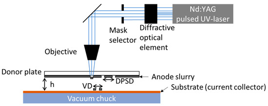
Figure 1.
Schematic illustration of the used LIFT setup. VD—voxel distance; DPSD—donor plate spot pitch; h—gap between the silicon ink and the substrate.
The anode ink is applied with a doctor blade (ZUA 2000, Proceq, Schwerzenbach, Switzerland) with a gap of 40 µm to a quartz glass wafer (DSP-200×0675-SGQ-00, Wafer Universe, Elsoff, Germany) with a thickness of 0.675 mm and a diameter of 200 mm, also referred to as a donor plate (DP). The used laser source is a frequency-tripled Nd:YAG laser (Lumentum, San Jose, CA, USA, model: Q301-HD-1000R), operating at a wavelength of 355 nm. The maximum average output power is 10 W, with a pulse duration of 78 ns and a laser repetition rate of 10 kHz, which can be increased up to 30 kHz. The diffractive optical element (DOE), shown in Figure 1, transforms the Gaussian laser beam intensity profile into a top-hat one. The top-hat intensity profile illuminates a mask selector with which different laser intensity profiles such as rectangles or circles of different sizes can be selected. The laser profile in the mask selector plane is imaged via the objective onto the backside of the donor plate with a demagnification factor of 3.5. By imaging the laser beam onto the interface between the anode ink and the quartz glass wafer, material is partially vaporized, resulting in material transfer towards the substrate [30,32]. In the case of anodes, a 9 µm thick copper foil substrate is located opposite to the anode ink. The copper foil is kept in position by a vacuum chuck. In addition to the hardware components, there are also important printing parameters, which are depicted in Figure 1. The first parameter is the donor plate spot pitch (DPSP). The DPSP is the distance of the ablations on the DP, and it is chosen to be large enough so that there is no overlap of the material ablation regions. The gap between the anode ink and the substrate (h) plays an important role for the needed laser power for a successful material transfer [33] with an adequate shape of thetransferred voxel [34]. For a line or areal printing, the distance between single voxels (VDs) has to be set in such a way that a defined and optimized overlap is realized [29]. Further parameters which are essential for the quality of material transfer are the viscosity of the ink [35] and the average laser power applied during the LIFT [36]. Prior to the printing process, the coated donor plates were stored under ambient conditions for 30 min to ensure a quasi-stationary state of the anode slurry on the donor plate regarding the evaporation of the solvents. A quasi-stationary state of the anode slurry is possible due to the low vapor pressure of glycerol in contrast to water and even NMP. The concentration of glycerol has to be precisely adjusted to ensure that the ink layer has a viscosity that can be printed in the long term. The LIFT process is carried out as described by Fernández-Pradas [37]. The partial vaporization of parts of the slurry with the laser creates a gas bubble at the interface between the donor plate and the donor substrate. The expansion and subsequent collapse lead to a transfer of material towards the substrate.
Following the printing, the electrodes were dried at 10 mbar at 80 °C for 24 h to ensure that no residual solvent remained. Afterwards, they were cut out with a diameter of 12 mm by using an ultrashort pulsed (USP) laser (Tangerine, Amplitude Systèmes, Pessac, France) operating at a wavelength of 515 nm. Before transferring the electrodes to an argon-filled glovebox, they were dried a second time under the same conditions in order to remove residual water. The electrodes were assembled in coin cells (CR2032) with lithium as a counter electrode. The used separator in the coin cells is a Celgard 2500 (Celgard LLC, Charlotte, NC, USA). The used electrolyte consists of a mixture of ethylene carbonate and ethyl methyl carbonate in a mass ratio of 3:7 with 1.3M LiPF6 with 5 wt.% fluoroethylene carbonate (FEC) as additives (Solvionic, Toulouse, France). The assembled coin cells were electrochemically characterized using a BT 2000 (Arbin Instruments, College Station, TX, USA) at 20 °C. Low electrical currents were applied in a long-term characterization, as shown in Table 3.
Table 3.
Discharge and charge currents, cut-off currents, and number of cycles of the long-term characterization of the electrodes.
The electrochemical priming of the cells was performed with one cycle at C/50 followed by three cycles at C/20. After the priming, the respective electrode capacity was calculated based on the discharge capacity of the last C/20 cycle and was set as the cell capacity for the following cycles. Subsequently, the cells were cycled symmetrically 50 times at C/10 to characterize the long-term stability of the material. The following three C/20 cycles were used to calculate the capacity retention (CR), by dividing the reached capacities at the end of the analysis by the reached capacities of the C/20 cycles in the priming process. The cells were cycled between 0.01 V and 1.5 V. During the discharging process, the cells were discharged with a constant current (CC) to the lower cut-off voltage. Afterwards, they were discharged at a constant voltage (CV) to a cut-off current, followed by a rest period of 15 min. Subsequently, the cells were charged to the upper cut-off voltage with a constant current (CC), with another rest period of 15 min afterwards. The currents and the associated limit values are regulated as displayed in Table 3.
The error bars in the bar plots in Section 3.1.2 and Section 3.2.2 display the standard deviation of the measured half-cells for this work.
The displayed specific discharge capacities of silicon are calculated by subtracting the specific discharge capacities of the conductive additives, since these materials also store lithium ions during the lithiation process (Table A2). Since the conductive additives are added with the same weight as silicon, the specific capacity of the silicon is calculated by subtracting the average measured specific capacity of the conductive additives for each cycle to consider the capacity fading related to the conductive additives. For this purpose, electrodes solely with the conductive additives are manufactured and cycled with the same analysis protocol.
The topography and geometry of the printings were analyzed with a microscope from Carl Zeiss Microscopy GmbH (Axio Lab A1, Göttingen, Germany).
To further investigate the difference between the printed electrodes with the fresh and the aged slurry (Section 3.4) Raman spectroscopy was performed with a micro-Raman system (Horiba LabRAM Odyssey, λ = 532 nm, Kyoto, Japan). Additionally, laser-induced breakdown spectroscopy (LIBS, FiberLIBS SN013, λ = 1064 nm, Secopta Analytics GmbH, Berlin, Germany) and energy dispersive X-ray spectroscopy (EDX, PW-100-018, Phenom-World BV, Eindhoven, The Netherlands) were used to further analyze the electrodes regarding their oxygen content.
3. Results and Discussion
First, the influence of the conductive additive on the slurry rheology was investigated, since this has a significant impact on the printability. For this purpose, two conductive additives with different particle sizes were used. Following the printing process, the electrochemical performances, such as capacity and long-term stability at low currents, were analyzed. In our approach, a new binder–solvent system was introduced for the printing process, and the impact of glycerol in slurries was systematically studied, while in the former battery research so far only a fraction of glycerol was applied for coated electrodes [38]. However, a water–glycerol mixture was already used as solvent in the printing process with other materials and with a very low solid content [26,29,39,40]. Both printing quality and electrochemical performance as long-term stability were investigated in the following. Since the used electrodes have a different areal capacity, the influence of the areal capacity of the electrodes on the electrochemical performance was considered as a function of the conductive additive. Finally, the effect of the glycerol content on the aging of the slurry was considered; so, the degradation of the material was investigated.
3.1. Influence of Conductive Additives
Prior to the characterization of the electrochemical performance of the newly developed ink, the printing quality has to be optimized in dependence of the ink composition. First, the influence of the conductive additives and the solid content (SC) of the ink on the viscosity and thus the printing and drying behavior is investigated and discussed.
3.1.1. Printing Quality
After preparing the ink, the viscosity was measured, as it has a significant influence on how precisely the voxel depicts the laser beam profile and so has an impact on the edge quality of the printed area and on the evenness of the surface. In the work of Mathews et al. and Piqué et al. (2008 and 2013) [35,41,42], high viscosities between 90 Pas and 150 Pas show an accurate transfer of the laser beam profile, while at low viscosities below 50 Pas the voxels lose their shape due to the ink running off. At very high viscosities above 500 Pas, the voxels are brittle and break up into small pieces during transfer. The viscosity for the printing thus shows a tendency, but due to a different material system with different particle sizes, the values of the optimum are not expected to be comparable. For the characterization of the slurry regarding the rheology, two different additives were used, carbon black (C65) and conductive carbon (KS6L). Also, two different solid contents—20 wt.% and 29 wt.%—and their impact on the surface and the edge quality of the printed layer are discussed. The measured viscosity of the manufactured slurries is displayed in Figure 2.
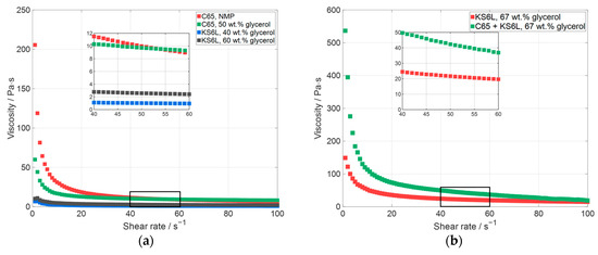
Figure 2.
Measured viscosity of manufactured slurries, (a) with a solid content of 19–20 wt.% and (b) with a solid content of 29 wt.% (C65—carbon black, KS6L—conductive graphite).
In Figure 2, the measured viscosity is displayed over the shear rate. All the slurries displayed in Figure 2a have an almost similar solid content between 19 wt.% and 20 wt.%. The solid content was chosen because with a higher solid content the viscosity of the slurries only containing carbon black was too high for the material to be mixed. Figure 2a shows the slurry containing silicon with NMP as the solvent and carbon black as the additive, which was used for printing in a previous work [11]. Additionally, slurries containing silicon with a mixture of water and glycerol as the solvent, one with C65 and two with KS6L as conductive additives, are displayed. The silicon-based slurry with NMP (Figure 2a, red) and the one with 50 wt.% glycerol and carbon black (Figure 2a, green) have a similar viscosity at a shear rate between 50 s−1 and 55 s−1. If the carbon black is substituted by larger particles, namely conductive graphite particles, the viscosity can be reduced [43]. With a lower viscosity, the solid content of a slurry can be further increased, leading to a reduced shrinkage and crack formation of the printed layer during the drying process. Additionally, during the LIFT process the mass transfer efficiency can be increased and thus the processing time can be reduced. In Figure 2b, the viscosities of the slurries containing silicon are displayed for a solid content of 29 wt.% and a glycerol content in the solvent mixture of 67 wt.%. For the C65 + KS6L slurry (Figure 2b, green), C65 and KS6L were added at a ratio of 50:50 as a conductive additive. This slurry has a viscosity of 42 Pas at a shear rate of 50 s−1. By substituting all C65 with KS6L (Figure 2b, red), the viscosity can be reduced by a factor of two (22 Pas @ 50 s−1), which in general indicates a better coating behavior with regard to the adhesion to the donor plate and the height uniformity on the donor plate.
After the printing, the deposited layers have to be dried. For this purpose, the electrodes with the slurries containing glycerol were dried at 10 mbar at 80 °C for 24 h, since the electrode slurry dries far too slowly under ambient conditions. The electrode with the NMP-containing slurry was dried under ambient conditions. The resulting surface topographies of the dried electrode layers are displayed in Figure 3.
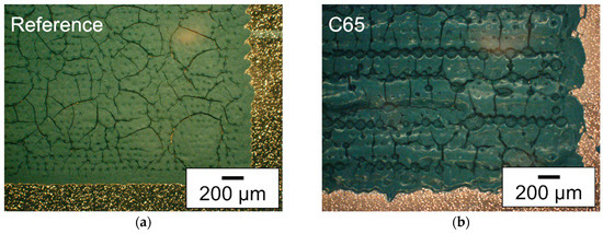
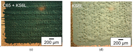
Figure 3.
Microscope images (dark field filter) of deposited silicon-based layers with different slurry compositions: (a) as reference, the silicon-containing slurry with NMP as solvent and C65 as additive (SC: 20 wt.%), (b) slurry with water and glycerol as solvent and C65 as additive (SC: 20 wt.%), (c) slurry with water and glycerol as solvent and C65 and KS6L—with a ratio of 50:50—as conductive additive (SC: 29 wt.%), and (d) slurry with water and glycerol as solvent and KS6L as conductive additive (SC: 29 wt.%).
The microscope images each show a section of the printed 13 × 13 mm2 area of an electrode. For each deposited layer, surface pores or even holes could be detected. One explanation may be due to the phenomenon described by Sopeña et al. [44], that holes appear in the center of a voxel at higher laser fluences. For the investigation of the laser parameters, first the distance between the slurry on the donor plate and the copper foil was adjusted to 100 µm. Then, the needed laser power was investigated as described in [33]. Afterwards a suitable spot distance at the donor plate was selected, at which the printed voxels were not affected by the previous ablation on the donor plate. This was followed by a voxel to voxel distance analysis, at which distance a closed printed line could still be realized on the substrate, as described in [29]. If the quality of the printing was low, the investigation of the laser parameters was repeated with a different distance from the slurry on the donor plate to the copper foil. The laser parameter for the printing of the electrodes can be seen in Table A1. In Figure 3a, a section of the printed area with the slurry containing silicon with NMP as the solvent and C65 as the additive is shown. That slurry type has already been used in a previous work and therefore is used as a reference for the comparison of the print quality of the newly developed slurries [11]. It can be seen that the edge of the layer is less precise and that crack formation occurs due to subsequent shrinkage of the layer. The layer in Figure 3b, which has also a solid content of 20 wt.%, shows many cracks after drying. In addition, the edge of the printing is less accurate than the presented layer in Figure 3a. With partial or complete replacement of carbon black by conductive graphite and the possible increase in solid content, almost no cracks were formed; see Figure 3c,d. For the two layers with increased solid content, there is a small amount of debris at the edges, slightly more for the layer with the mixture of C65 and KS6L (Figure 3c). By increasing the solid content of the used slurry, the formation of cracks can be reduced. This can be related to a reduced shrinkage during drying of the printing.
3.1.2. Electrochemical Performance
As PVDF is not a suitable binder for silicon-containing electrodes [45,46,47,48,49], only the PAA and glycerol-containing electrode pastes were used to print electrodes with a footprint of 13 × 13 mm2. Following the printing, the electrodes were cut out with an USP laser and assembled in coin cells (CR2032) versus lithium for analyzing the electrochemical performance. At first, the assembled cells were cycled as displayed in Table 3, with a priming process; subsequently, 50 cycles were applied at C/10.
The impact of different conductive additives on the specific capacity is shown in Figure 4. In the diagram, the specific discharge capacity is displayed over the number of cycles. At the end of the priming process, all cells achieve a specific discharge capacity of at least around 3000 mAhg−1 or higher, i.e., all cells are quite close to the theoretical specific capacity at room temperature for the fully alloyed Li15Si4 of 3579 mAhg−1 [5,50]. The cells only containing C65 as an additive have the lowest specific capacity at the end of the priming compared to the other cells. This might be due to differences in absolute areal capacities. More detailed information about the respective electrochemical data of the cells is given in Figure 5. After the priming process, the cells are cycled at a C-rate of C/10. Compared to the C65 + KS6L cell and the KS6L cell, the C65 cell has a significantly higher capacity fade. The higher areal capacity of the electrodes with C65 can be one reason why the capacity fading at the C/10 cycles is much higher than at the other cells, but the crack formation during the drying process could also be a reason for the detected capacity decay. Also, the specific capacity of the last three C/20 reference cycles of the C65 cell is much lower than the specific capacity of the first three C/20 cycles. In Section 3.3 the influence of the areal capacity on the capacity fading during cycling due to a different areal capacity is discussed in more detail. The C65 + KS6L cell showed the highest specific capacity, but a higher capacity decay than the KS6L cell at the 50 C/10 cycles. One possible explanation for the faster decrease during the electrochemical priming at a C-rate of C/20 in the cells with C65 electrodes could be the small particle size of C65. Larger particles (KS6L) in the electrode layer lead to larger pores, which give the silicon more space to expand during lithiation, resulting in a lower capacity fading during cycling. Also, the silicon particles are much smaller than the KS6L particles, leading to a better adhesion on the surface of the bigger particles, but further investigations are needed.
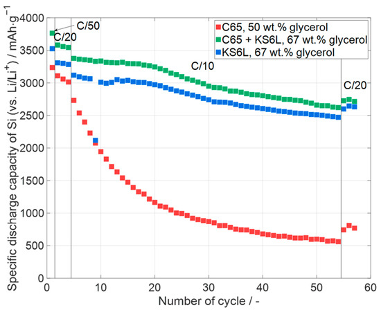
Figure 4.
Specific discharge capacity of silicon in printed silicon-containing electrodes (one representative example per type) with different conductive additives (C65—carbon black, KS6L—conductive graphite). Error bars are excluded for clarity. Data for all cells, including deviations, are shown in Figure 5.
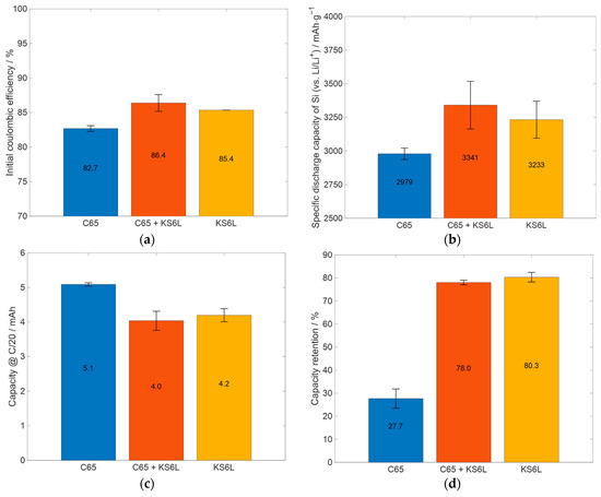
Figure 5.
Summary and comparison of relevant electrochemical data of the cells prepared with slurries with different glycerol content: (a) initial coulombic efficiency, (b) specific capacity of silicon (excluding the capacity of the conductive additives from total capacity, see Table A2) at the end of the priming process, (c) the absolute capacity at the last C/20 cycle of the priming process, and (d) the capacity retention, when comparing the capacity of the first three C/20 cycles with the last three.
For a better comparison of further electrochemical properties, the values for the initial coulombic efficiency, the capacity of silicon in the electrodes at the end of the priming process, the absolute capacity at the end of the priming process, and the capacity retention are displayed in Figure 5.
In Figure 5a, the initial coulombic efficiency (ICE) is displayed for the cell types shown in Figure 4. The ICE value indicates how much lithium is irreversibly consumed by reactions during the first lithiation cycle and therefore cannot be transferred back to the lithium electrode during delithiation. One consumption reaction is the development of a solid electrolyte interphase on the surface of the particles of the electrode [51]. Since the used cells were half-cells, lithium is available in excess due to the lithium metal electrode. The ICE is lower for the C65 cells compared to the other ones, and that of the C65 + KS6L cells has the highest ICE. This cannot be only explained by the coulombic efficiencies of the different conductive additives, because C65 has a much lower ICE compared to KS6L, as shown in Table A2, which is thus in contrast to the higher ICE measured for the C65 + KS6L cells compared to the KS6L cells. With an ICE of 85% and 86%, the C65 + KS6L and the KS6L cells have a high ICE compared to silicon-containing anodes, which is between 49.6% and 93.8% [52,53]. From Figure 5b, it can be concluded that the silicon in the C65 + KS6L and KS6L cells provides almost the same specific discharge capacity and thus a slightly higher specific capacity compared to the C65 cells. The lower capacity retention of the C65 cells, as displayed in Figure 5d, can be partially explained by the higher absolute capacity of the cells, as shown in Figure 5c, and also the crack formation in the electrode layer, as shown in Figure 3b. It can be seen from Figure 5c, that the KS6L cells have a slightly higher capacity than the C65 + KS6L cells; in any case, the capacity retention of the KS6L cells after the C/10 cycles is a little higher than the one of the C65 + KS6L cells. Thus, it can be concluded that the adding of KS6L as a conductive additive increases the cycling stability at low currents, which will be also proven in Section 3.3.
3.2. Impact of Glycerol
Following the investigation of the influence of the conductive additives on printing quality and electrochemical performance, the impact of the glycerol content in the ink also has to be investigated regarding viscosity and thus the printability of the slurry and the electrochemical performance of the assembled cells.
3.2.1. Printing Quality
At first the influence of the glycerol content in the solvent on the edge quality of the area and the evenness of the surface was analyzed. For this purpose, slurries with water–glycerol mixtures ranging from 20 wt.% to 100 wt.% glycerol content were manufactured, and electrodes were subsequently printed. The viscosities of glycerol and water are 1433 mPas (@ 20 °C) and 1 mPas (@ 20 °C), respectively [31]; this leads to an increase in viscosity with the increase in the glycerol content. The viscosity of the slurry has a large influence on how accurately the voxel depicts the laser beam profile [35,41,42], which is described in more detail in Section 3.1.1. The viscosity of the printing inks was thus measured first (Figure 6). A slurry with only water as a solvent is not printable as the ink dries too fast.
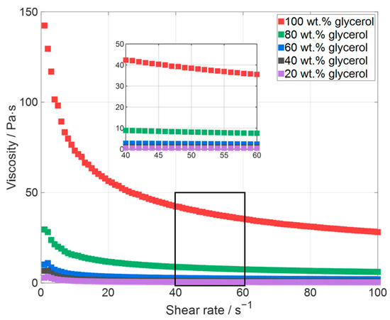
Figure 6.
Viscosities of the glycerol-containing slurries with different glycerol contents ranging from 20 wt.% to 100 wt.%.
A solid content of 19 wt.% for the silicon-containing electrode pastes for the investigation of the influence of the glycerol content was chosen because the electrode paste with only glycerol as a solvent has a viscosity of 38 Pas, and mixing pastes with significantly higher viscosities are difficult to process with the used mixer. As the glycerol content decreases, the viscosity initially decreases rapidly, although the decrease is less strongly pronounced below a glycerol content of less than 60 wt.%. All pastes have a shear thinning behavior, which is more pronounced for the paste with high viscosities.
After the measurement of the viscosity, electrodes with a footprint of 13 × 13 mm2 were printed with each slurry. For this purpose, the donor plate spot pitch, the voxel distance, and the average laser power were adjusted for each slurry type, as can be seen in Table A3. Microscopic images of the electrodes used for the electrochemical performance analysis are shown in Figure 7. Here, the printed electrodes and, for the sake of completeness, the tape cast silicon electrode with only water as a solvent are shown.
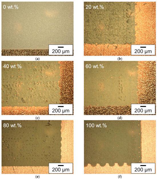
Figure 7.
Microscope images (dark field filter) of electrodes with (a) the coated electrode with 0 wt.% of glycerol, and the printed electrodes with (b) 20 wt.%, (c) 40 wt.%, (d) 60 wt.%, (e) 80 wt.%, and (f) 100 wt.% glycerol content in the solvent mixture. All electrodes are manufactured with an electrode paste with 19 wt.% solid content.
Contrary to most of the printed electrodes, the electrode produced by tape casting shows no hole formation. However, printed electrodes with only 20 wt.% glycerol in the solvent mixture also show no hole formations, but do have an uneven surface. This indicates that in the latter case, the transferred slurry with a high viscosity cannot spread out homogenously to compensate for small irregularities, but there is also no hole formed in the middle of a voxel. The holes for slurries with a higher glycerol content can be explained in the same way as in Section 3.1 [44]. Holes appear in the electrodes with increasing glycerol content in the solvent mixture, while most of the holes appear in the layer produced with 40 wt.% glycerol. The smallest number of holes, except the electrode printed with a slurry with 20 wt.% glycerol, appears for the printed electrode with 100 wt.% glycerol. This can be explained by the fact that almost no solvent evaporates before printing of the 100 wt.% glycerol slurry, and the viscosity of the slurry remains the same during printing. Since most parts of the water in the water-containing slurries evaporate prior to printing, the viscosity of the slurry with 100 wt.% glycerol should be the lowest during printing and can thus compensate for larger irregularities than the other ones. Here, the difference in the number of holes in the layers cannot only be explained by the different viscosities but also by the different laser parameters which were needed for the printing of an electrode layer; see Table A3.
3.2.2. Electrochemical Performance
After the analysis of the printing quality regarding the glycerol content, the electrodes were printed with the inks containing a glycerol content of 20 wt.% and higher. For reference, electrodes with only water as a solvent were tape cast via a doctor blade. Subsequently, all the electrodes were cut out with a USP laser and were examined using coin cell designs.
For the analysis of the electrochemical performance, the cells with silicon-containing electrodes were cycled with the cycling protocol provided in Table 3. The specific discharge capacity of the cells is displayed over the number of cycles in Figure 8. It can be seen that every electrode has a specific capacity of silicon at the end of the priming process of more than 3000 mAhg−1. This is quite close to the theoretical capacity of silicon (3579 mAhg−1), with the electrode manufactured with 0 wt.% glycerol showing the highest capacity. For the data shown in Figure 8, no obvious influence of the glycerol content can be observed. For all the cells, a fast decrease in capacity appears during some C/10 cycles. The reason for the faster capacity fading is not identified yet for the shown cells. It can be stated that the specific capacity of the cells with the electrodes with 40 wt.% and 80 wt.% glycerol is the highest specific capacity at the end of the analysis, followed by the cells with the electrodes with 20 wt.% and 100 wt.% glycerol. However, after the C/10 cycles all the cells have a specific capacity higher than 2000 mAhg−1, and four cell types (20 wt.%, 40 wt.%, 80 wt.%, and 100 wt.% glycerol) are even higher than 2500 mAhg−1. Nguyen et al. [53] reached a specific capacity of 3500 mAhg−1 at the first cycle of the long-term analysis for an electrode with 50 wt.% silicon nanoparticles. After 50 cycles at C/7, the electrodes still reached a specific capacity of 2750 mAhg−1, which resulted in a capacity retention of 78%. The specific capacities were calculated by only using the mass of silicon and neglecting the capacity of the used carbon black. Calculating this way, the values of the specific capacity at the end of the priming process of the cells in this work (Figure 8) would be in the range from 3330 mAhg−1 to 3557 mAhg−1, with a specific capacity between 2265 mAhg−1 and 2877 mAhg−1 after 50 cycles at C/10. The capacity retention here would be 64% to 82%. The calculation including the contribution of the conductive additives is presented in Figure 9. Ghamlouche et al. [54], Ha et al. [55], Zheng et al. [56], and Wetjen et al. [57] calculated the values of the specific capacity by using the mass of silicon and graphite. The order of the following values corresponds to the order in which the publications were named. The silicon contents of the cells in the works are 30%, 15 wt.%, 20 wt.%, and 35 wt.%. The achieved specific capacities at the first cycle of the long-term analysis are 1200 mAhg−1, 500 mAhg−1, 555 mAhg−1, and 1300 mAhg−1. The used C-rates for the cycling were C/10, C/3, C/2, and C/2. After 50 cycles, the cells in the published works had a specific capacity of 1080 mAhg−1, 360 mAhg−1, 450 mAhg−1, and 1125 mAhg−1. The calculated capacity retentions were 90%, 72%, 81%, and 87%. Taking the mass of silicon and KS6L for the calculation of the specific capacity, the cells in this work would exhibit a specific capacity between 1665 mAhg−1 and 1778 mAhg−1, which is higher because the used electrodes contain a higher silicon content. After 50 cycles of C/10, the specific capacity of the cells would range from 1132 mAhg−1 to 1438 mAhg−1, with the same capacity retention ranging from 64% to 82%. To summarize, the cells in this work have a high specific capacity compared to other published works and the capacity retention of the cells after 50 cycles with up to 82% is a comparable value; in any case, it has to be taken into account that different amounts of silicon were used for the cells and that the long-term analysis was made at a different C-rate. Even the mass loading of the cells was different, which makes the comparison difficult.
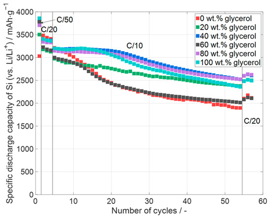
Figure 8.
Specific discharge capacity of silicon in printed silicon-containing electrodes (one representative example per type) with different glycerol contents in the slurry ranging from 20 wt.% glycerol to 100 wt.%. The reference electrode with 0 wt.% glycerol was tape cast via doctor blade. Error bars are excluded for clarity. Data for all cells, including deviations, are shown in Figure 9.
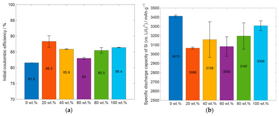
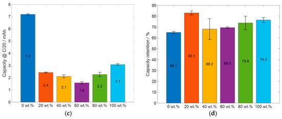
Figure 9.
Summary and comparison of important electrochemical results of the cells prepared with slurries with different glycerol content: (a) initial coulombic efficiency, (b) specific capacity of silicon (excluding the capacity of KS6L from total capacity, see Table A2), (c) the absolute capacity at the last C/20 cycle of the priming process, and (d) the capacity retention, when comparing the capacity of the first three C/20 cycles with the last three.
For a better comparison of the electrochemical performance of the cells, the initial coulombic efficiency, the specific capacity of silicon, the capacity of the cells at the end of the priming process, and the capacity retention after the 50 C/10 cycles are displayed in Figure 9. Figure 9a displays the ICE of the cell types shown in Figure 8. All the cell types which had glycerol in the slurry have a higher initial coulombic efficiency than the reference cell, which was manufactured without glycerol. Furthermore, the cells prepared with 20 wt.% glycerol have the highest ICE, and the cells which were manufactured with 60 wt.% glycerol have the lowest ICE. The cells with the electrodes prepared with 40 wt.%, 80 wt.%, and 100 wt.% glycerol have almost the same ICE, between 85% and 86%. The ICE values of the displayed cells are comparable for the initial coulombic efficiency for silicon-containing electrodes, with an ICE of 82% for silicon nanoparticles, as reported by Nguyen et al. [53], and ranging from 49.6% up to 93.8% ICE, as reported by Wang et al. [52]. The specific capacity of silicon at the end of the priming process, excluding the capacity of the KS6L from the total capacity, is shown in Figure 9b. The silicon in all the cell types has a specific capacity higher than 3000 mAhg−1. The cells which were produced without glycerol have the highest specific capacity of about 3400 mAhg−1, which is close to the theoretical specific capacity of silicon of 3579 mAhg−1 [5]. For the cells which were manufactured with glycerol, the cell with 100 wt.% glycerol as the solvent has the highest specific capacity, but here the differences in values are less than 250 mAhg−1. One possible explanation for the higher specific capacity of silicon in the electrodes manufactured without glycerol, compared to those with glycerol, could be the presence of fewer defects in the electrode layer. Additionally, it is observed that the silicon in the electrode produced with 100 wt.% glycerol, which exhibits the fewest defects and most uniform structure, shows the highest specific capacity among the printed electrodes. The assumption would be that the number of surface defects correlates with limitations in electrode adhesion to the current collector. Reduced adhesion would lead to increased ohmic resistivity, which in turn would lead to increased overpotential and thus a decrease in capacity, and forced mechanical degradation due to volume expansion during cycling would also be expected. However, it is important to note that other factors may also contribute to these differences, and further investigation is needed to fully understand the cause of these variations.
When comparing the specific capacity of the C/20 cycles before the 50 C/10 cycles with the C/20 cycles afterwards, as shown in Figure 9d, the electrodes which were manufactured without glycerol and the electrodes which were manufactured with 40 wt.% glycerol have the lowest capacity retention. For the electrodes which were manufactured without glycerol, this can be partially explained with the much higher absolute capacity at the end of the priming process; see Figure 9c. The influence of the absolute capacity of the cell on the capacity retention is further discussed in Section 3.3. Another explanation could be the different manufacturing process. In the LIFT process, the material is transferred at a velocity orthogonal to the current collector, thereby achieving better wetting behavior with small surface irregularities; this follows the Wenzel wetting behavior [58]. This could lead to an increase in adhesion to the current collector, resulting in better cyclability. Furthermore, it can be seen that the cells containing electrodes which were manufactured with 20 wt.% glycerol have the highest capacity retention. For the electrodes which were manufactured with 40 wt.% glycerol and more, a slight increase in capacity retention with increasing glycerol content in the slurry can be observed. Due to the high specific capacity of silicon, it can be concluded that the glycerol does not react with the used materials. However, there are differences in the electrochemical properties of the electrodes with different glycerol content, but no linear dependence of the glycerol content on the electrochemical properties can be derived so far from the achieved results. The difference in capacity could be due to other influencing factors, such as the different viscosity of the slurries, the different number of holes and pores in the electrode layer, a small difference in the handling time in ambient air, or a small difference in the storage time in the glovebox before assembling the electrodes in the coin cells, to name a few. Further investigations into the impact of these aspects are, however, needed.
3.3. Influence of the Areal Capacity
As indicated in Section 3.1 and Section 3.2, some electrodes have a higher areal capacity; therefore, the influence of the areal capacity on the electrochemical performance has to be investigated for the cells presented in this work. For this purpose, the electrodes manufactured with only C65 as an additive and 50 wt.% glycerol as a solvent (see Section 3.1) and the electrodes manufactured with KS6L and only water as a solvent (see Section 3.2) were manufactured with two different areal capacities, and the electrochemical results are displayed in Figure 10.
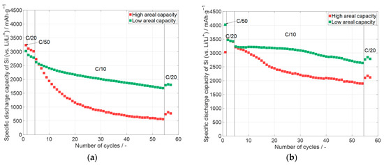
Figure 10.
Specific discharge capacity of silicon in silicon-containing electrodes with different areal capacity (one representative example per type): (a) C65 and 50 wt.% glycerol (see Section 3.1), average areal capacity: high: 4.50 mAhcm−2, low: 1.50 mAhcm−2, and electrode thickness of 91 µm and 25 µm, respectively; (b) KS6L and 0 wt.% glycerol (see Section 3.2), average areal capacity: high: 6.35 mAhcm−2, low: 1.12 mAhcm−2, and electrode thickness of 50 µm and 16 µm, respectively. Error bars are excluded for clarity. Data for all cells, including deviations, are shown in Figure 11.
The specific discharge capacities are displayed over the number of cycles in Figure 10. In the diagrams, the cells with a high areal capacity and low areal capacity are compared to each other. For the cells with the C65 electrodes (see Section 3.1) and the KS6L electrodes (see Section 3.2), the cells with the high areal capacity electrodes have at the end of the priming process a specific capacity for silicon greater than 3000 mAhg−1. For both electrode types, the cells with the high areal capacity electrodes undergo a faster capacity fading during cycling than the ones with lower areal capacity. When comparing both diagrams, it can be stated that the cells with the KS6L electrode undergo a smaller capacity fading compared to their counterparts in terms of the areal capacity with a different conductive additive. The higher capacity fade of the cells with the electrodes with only C65 may be due to the higher electrode thickness and a resulting higher porosity of the electrodes compared to their counterparts with KS6L as a conductive additive. Overall, it can be concluded that a higher areal capacity causes a faster capacity decay even at low currents of C/10. The capacity fading during the cycling of cells with KS6L (micrometer particles) as a conductive additive is lower than with C65 (sub-micrometer particles).
To summarize the influence of the absolute electrode capacity on capacity retention, the capacity of the cells at the end of the priming process and the capacity retention after the 50 C/10 cycles are shown in Figure 11.
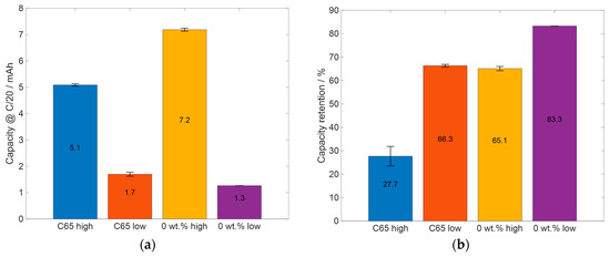
Figure 11.
Summary and comparison of relevant electrochemical data: (a) the capacity at the last C/20 cycle and (b) the capacity retention after the 50 C/10 cycles.
The capacity retention of the cells is displayed in Figure 11b. After the 50 C/10 cycles, the cells with high areal capacity C65 electrodes have a capacity retention that is more than 30% smaller than the one with low areal capacity. For the electrodes with KS6L as a conductive additive, the difference in capacity retention between the electrodes with high areal capacity and the one with low areal capacity is smaller than 20% and smaller than those for the C65 cells. When comparing the differences in the capacities at the last cycle of the priming process (Figure 11a), it can be seen that the C65-containing electrodes have a difference in capacity of about 3.4 mAh, whereas the electrodes manufactured with KS6L as a conductive additive and 0 wt.% glycerol have a capacity difference of 5.9 mAh. Additionally, the cells containing electrodes with high areal capacity with 0 wt.% glycerol have an absolute capacity, which is about 2.1 mAh higher than the C65 cells with high areal capacity electrodes. When comparing the capacity retention of the C65 cells with low areal capacity electrodes with the one of the 0 wt.% glycerol cells with high areal capacity, the 0 wt.% glycerol electrodes have slightly smaller but similar capacity retentions. This shows that the cells with the electrodes with KS6L as the conductive additive have a lower capacity fade during cycling than the cells with the C65 electrodes. One explanation could be the larger particle size of KS6L, which is about 100 times larger than the silicon particles. Silicon has a low conductivity; so, it could be an advantage that the smaller silicon particles can adhere to the surface of the larger ones and that the larger ones can form a conductive lattice. This is in contrast to C65, where the particles are only up to five times the size of silicon particles, which could lead to a worse contact between the C65 particles. Furthermore, the bigger pores through bigger particles could also be an advantage, as described above.
3.4. Effect of Glycerol Content on Slurry Aging
As oxidation takes place when the silicon nanoparticles are processed under air or in water, the long-term stability of the slurries with different amounts of glycerol in the solvent mixture needs to be evaluated. The slurries with 60 wt.% and 100 wt.% glycerol were printed and electrochemically analyzed, 112 days and 222 days, respectively, after the slurry was manufactured. In Figure 12, the data from the electrochemical characterization of the printed electrodes are presented.
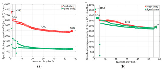
Figure 12.
Specific discharge capacity of the electrodes containing silicon which were printed with different glycerol contents, but each glycerol content with the same slurry occurred at different times after slurry preparation, whereas the first electrode was printed 24 h after the slurry manufacturing, with (a) 60 wt.% glycerol content and a delay of 112 days and (b) with a glycerol content of 100 wt.% and a time delay of 222 days.
In both diagrams of Figure 12, the specific discharge capacity is displayed over the number of cycles. In contrast to the shown diagrams (Figure 4, Figure 8 and Figure 10), the whole capacity of the cell is related to the mass of the used silicon, because the influence of oxidation on the individual materials cannot be determined. The electrodes which were manufactured with 60 wt.% glycerol are displayed in Figure 12a. The electrodes with the fresh slurry were printed one day (24 h) after the manufacturing of the slurry. Additional electrodes were printed with the same slurry after 112 days. It is evident that the specific capacity of the electrodes with the aged slurry shows much lower values compared to the electrodes printed one day after the manufacturing of the slurry. A possible explanation is that the silicon partially oxidized due to contact with the water of the slurry. The formed silicon oxide has a lower specific capacity compared to pure silicon [59], which will be further analyzed later. Figure 12b shows the cells with the electrodes printed with 100 wt.% glycerol. The fresh electrodes were printed 24 h after the slurry was prepared, and the electrodes with aged slurry were printed with a time delay of 222 days after the slurry manufacturing. This is 110 days more than the electrodes prepared with 60 wt.% glycerol. The electrodes manufactured with the aged slurry (100 wt.% glycerol, Figure 12b) have almost the same specific capacity as the electrodes which were manufactured 24 h after the preparation of the slurry. It can be stated that slurry with 100 wt.% glycerol can suppress the oxidation of silicon particles in the time scale of the analysis. Such slurry types are quite useful for long-term usage; however, the viscosity of the slurries with 100 wt.% glycerol is higher than with a lower glycerol content—see Section 3.2—and therefore has disadvantages when, for example, increasing the solid content.
Raman spectroscopy and laser-induced breakdown spectroscopy (LIBS) were applied to further characterize the differences in the pristine and printed electrodes (fresh and aged) with 60 wt.% glycerol. The results of the measurement are presented in Figure 13.
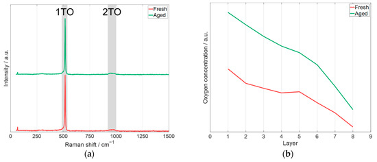
Figure 13.
Spectroscopy measurements of pristine electrodes of the electrodes prepared with fresh and aged slurry (Figure 12) with 60 wt.% glycerol: (a) Raman spectroscopy measurement (laser excitation wavelength: 532 nm), (b) depth profile of oxygen concentration obtained by LIBS (laser excitation wavelength: 1064 nm) based on the intensity of oxygen emission line (O(I): 777.3 nm, [60]).
The Raman spectroscopy measurements of the electrodes manufactured with fresh and aged slurry are shown in Figure 13a. The 1TO and 2TO are mapped according to [61]. These bands are associated with crystalline silicon. Comparing the measurement between the printed electrode prepared with fresh and aged slurry leads to the conclusion that there is no measurable difference with Raman spectroscopy. Figure 13b shows the relative change in the oxygen concentration of the electrodes achieved by LIBS measurements. The presented data are average values for each measured layer of the electrode. After nine pulses, a copper signal was detected, which means the current collector was reached. Since the electrode thickness is 20.5 ± 0.5 µm, this results in an average ablated thickness of 2.31 ± 0.05 µm per pulse. In Figure 13b, layer 0 represents the surface of the electrode. The results of the measurement of layer 0 are not shown, as the first pulse at a measurement position is a cleaning process because the surface could be contaminated from removals from previous positions. It can be clearly seen that the electrode manufactured with fresh slurry always has a lower oxygen concentration compared to the electrode prepared with the aged slurry, which supports the statement that a significant oxidation of Si particles takes place during aging of the slurry. However, it should be noted that the oxygen concentration reaches a maximum at the top of the electrode, which is due to the fact that the electrodes were handled in air after the printing process, causing further oxidation of the printed layers.
To further characterize the difference between the electrodes, X-ray spectroscopy (EDX) was applied with area measurement and point measurement, and the results are displayed in Table 4.
Table 4.
EDX measurement of pristine electrodes of the electrodes prepared with fresh and aged slurry (Figure 12) with 60 wt.% glycerol. The ratio of silicon to oxygen is shown in brackets after the values for silicon.
Comparing the area measurements of the electrodes prepared with fresh and the aged slurry, a higher oxygen content is observed for the electrode manufactured with aged slurry at a lower silicon content, but a higher carbon content. It can be stated that the material of the electrode produced with the aged slurry is more oxidized. In order to better characterize whether the oxygen is more localized in the silicon, a point measurement was taken with high silicon content. It can be seen that for the electrode manufactured with fresh slurry, the detected oxygen content is similar to the oxygen content of the area measurement, whereas the oxygen content for the electrode printed with the aged slurry is higher than the oxygen content of the area measurement. In the brackets after the values for silicon, the ratio of silicon to oxygen is displayed. There is more silicon per oxygen in the measured fresh sample than in the aged sample, which indicates a stronger oxidation of the silicon in the aged sample. It can be concluded that element-sensitive spectroscopy methods, such as LIBS and EDX, indicate oxidation of the material, whereas Raman spectroscopy, which probes the vibrational modes of the material, shows no noticeable change. This discrepancy may be due to the formation of an amorphous oxide, resulting in a broad, featureless signal or the presence of a Raman-inactive species.
4. Conclusions
For the LIFT process, PVDF has so far mostly been used as a binder for the printing of electrodes. However, the binding forces between the binder and the silicon particles are too weak to withstand the huge volume change during cycling. Therefore, polyacrylic acid (PAA), a commonly used binder for silicon-containing electrodes, was introduced as a binder for the printing of anode materials with the LIFT process. PAA is a hydrophilic binder, but due to the fast evaporation of water, the slurry with only water as a solvent is not printable in practice. For this purpose, glycerol, which has a much lower vapor pressure compared to water, was added in different amounts to the solvent. In research, glycerol was used for performing the LIFT process, but it was the first time the LIFT process was performed with glycerol as a solvent and PAA as binder for printing electrodes. After the manufacturing of the slurry, the viscosity was measured, and the electrodes were printed via the LIFT process and assembled in coin cells against lithium for electrochemical analysis. At first, the cells underwent a priming process with one cycle at C/50 and three cycles at C/20. Subsequently, the cells were cycled 50 times at C/10 followed by three cycles at C/20. The influence of different conductive additives—carbon black with a particle size between 100 µm and 500 µm and conductive carbon with an average particle size of 7.47 µm—was investigated regarding the printing quality and the electrochemical performance. With the larger particles—conductive graphite—the manufactured slurries have a lower viscosity and the cyclability of the electrodes in a half-cell is increased. The specific initial capacity of the cells with the electrode containing silicon is larger than 3000 mAhg−1 and only slightly influenced by the type of additive. The cells with the electrodes with a mixture of C65 and KS6L have a slightly higher specific capacity than the other ones. In contrast, the cells with only KS6L have some degree of higher cycling stability than the other cells.
Afterwards, the impact of the glycerol content was investigated. For this purpose, slurries with a glycerol content ranging from 20 wt.% glycerol to 100 wt.% glycerol as a solvent were printed with the LIFT process. Additionally, a reference electrode was coated by a doctor blade with only water as a solvent. For this purpose, KS6L was used as a conductive additive because of the better cycle stability. The electrodes were electrochemically characterized in the same way as the cells with the different conductive additives. All the cells had a specific capacity above 3000 mAhg−1; so, it can be stated that the glycerol as a solvent does not affect the electrochemical performance. There are differences between the cells with the electrodes manufactured with different amounts of glycerol, but linear correlation between the glycerol content and the electrochemical properties could not be identified. It can be stated that the cells with electrodes which were manufactured without glycerol had the highest specific capacity of silicon at the end of the priming process and also a good capacity retention with the lower areal capacity. For the cells with the printed electrodes, the cells with the electrodes prepared with 20% glycerol had the highest capacity retention; however, it has to be mentioned that the initial specific capacity of silicon was one of the lowest. As silicon oxidizes in the presence of oxygen or water, how the long-term chemical stability of the slurry was influenced by the glycerol content was investigated. For this purpose, in addition to the printed electrodes with freshly prepared slurry, electrodes were printed with aged slurries. It could be shown that the electrode which was manufactured with 60 wt.% of glycerol and was printed with aged slurry showed reduced electrochemical performances. In contrast, the electrodes which were printed using a slurry containing 100 wt.% of glycerol showed independence from the slurry age and the stable electrochemical performance.
In terms of the glycerol variation with the consideration of specific capacity, capacity retention, slurry stability, and printability, the cell with the electrode produced with 100 wt.% glycerol and KS6L as a conductive additive showed the best results. One of the disadvantages of this slurry with regard to processability is the high viscosity, which limits the increase in solid content. Increasing the solid content would increase the efficiency of the LIFT process and lead to less shrinkage during the drying process and therefore fewer cracks in the dried electrode. The slurries with a solid content of 29 wt.% and 67 wt.% glycerol (Section 3.1.1 and Section 3.1.2) represent a further development step, since capacity retention and printability increase with increasing solid content.
In ongoing research, the slurry composition will be optimized by further increasing the silicon content. Slurries with less than 100 wt.% glycerol offer a better coating behavior and provide a lower viscosity; so, the solid content can be further increased to increase the process efficiency. Additionally, the decay of slurry/ink performance should be investigated more closely regarding the glycerol content, to determine the time period in which the slurries with less than 100 wt.% glycerol are stable. As part of the ongoing research into the long-term stability of the produced slurries, it is essential to flank the electrochemical characterizations with spectroscopic and chemical analyses to verify at the material level whether or not a chemical reaction with glycerol takes place. Finally, the volumetric capacity and probably also the electrode adhesion could be increased by substrate structuring [62] and the calendering process [63].
Author Contributions
Conceptualization, U.R. and W.P.; funding acquisition, W.P.; investigation, U.R.; methodology, U.R.; project administration, W.P.; resources, U.R. and W.P.; supervision, W.P.; validation, U.R.; visualization, U.R.; writing—original draft, U.R.; writing—review and editing, W.P. All authors have read and agreed to the published version of the manuscript.
Funding
This research was funded by the Deutsche Forschungsgemeinschaft (DFG, German Research Foundation)—Project number: 467624762.
Data Availability Statement
The original contributions presented in this study are included in the article. Further inquiries can be directed to the corresponding authors.
Acknowledgments
We are grateful to our colleague Marek Kapitz for the support in the laser processing, to Alexandra Reif for the support in EDX and LIBS measurements, to Viktoria Falkowski for her support in Raman spectroscopy and the scientific discussions, and to the working group of Theo Scherer for providing access to Raman spectroscopy.
Conflicts of Interest
The authors declare no conflicts of interest.
Abbreviations
The following abbreviations are used in this manuscript:
| C65 | Carbon black |
| CC | Constant current |
| CR | Capacity retention |
| CV | Constant voltage |
| DOE | Diffractive optical element |
| DP | Donor plate |
| DPSD | Donor plate spot pitch |
| EDX | X-ray spectroscopy |
| FEC | Fluoroethylene carbonate |
| ICE | Initial coulombic efficiency |
| KS6L | Conductive graphite |
| LIBS | Laser-induced breakdown spectroscopy |
| LIFT | Laser-induced forward transfer |
| NMP | N-Methyl-2-pyrrolidone |
| PAA | Polyacrylic acid |
| PVDF | Polyvinylidene fluoride |
| SEI | Solid electrolyte interface |
| SC | Solid content |
| USP | Ultrashort pulsed |
| VD | Voxel distance |
| h | Gap between the silicon ink and the substrate |
Appendix A
Table A1.
Printing parameters for the electrodes, which are shown in Figure 4.
Table A1.
Printing parameters for the electrodes, which are shown in Figure 4.
| Electrode | Fluence/J∙cm−2 | Donor Plate Spot Pitch/µm | Voxel Distance/µm | Distance/µm | Print Speed/mm∙s−1 |
|---|---|---|---|---|---|
| C65 | 0.73 | 220 | 105 | 100 | 1 |
| C65 + KS6L | 0.61 | 270 | 160 | 50 | 1 |
| KS6L | 0.73 | 220 | 105 | 150 | 1 |
Table A2.
Average values of the electrochemical analysis of the conductive additives in the electrode.
Table A2.
Average values of the electrochemical analysis of the conductive additives in the electrode.
| Material | Initial Coulombic Efficiency/% | Average Specific Discharge Capacity (@ C/20)/mAh∙g−1 | Capacity Retention/% |
|---|---|---|---|
| C65 | 28.41 ± 0.54 | 246 ± 11.28 | 92.44 ± 1.98 |
| KS6L | 68.65 ± 2.21 | 365 ± 1.51 | 97.76 ± 0.2 |
Table A3.
Printing parameter for the electrodes, which are shown in Figure 8.
Table A3.
Printing parameter for the electrodes, which are shown in Figure 8.
| Electrode | Fluence/J∙cm−2 | Donor Plate Spot Pitch/µm | Voxel Distance/µm | Distance/µm | Print Speed/mm∙s−1 |
|---|---|---|---|---|---|
| 20 wt.% | 0.42 | 240 | 105 | 100 | 2 |
| 40 wt.% | 0.47 | 230 | 110 | 100 | 2 |
| 60 wt.% | 0.42 | 230 | 110 | 100 | 1 |
| 80 wt.% | 0.47 | 240 | 105 | 100 | 1 |
| 100 wt.% | 0.56 | 240 | 120 | 250 | 1 |
References
- Pfleging, W. Recent progress in laser texturing of battery materials: A review of tuning electrochemical performances, related material development, and prospects for large-scale manufacturing. Int. J. Extreme Manuf. 2021, 3, 012002. [Google Scholar] [CrossRef]
- Minakshi, M.; Mitchell, D.R.G.; Munnangi, A.R.; Barlow, A.J.; Fichtner, M. New insights into the electrochemistry of magnesium molybdate hierarchical architectures for high performance sodium devices. Nanoscale 2018, 10, 13277–13288. [Google Scholar] [CrossRef] [PubMed]
- Xiao, J.; Li, H.; Zhang, H.; He, S.; Zhang, Q.; Liu, K.; Jiang, S.; Duan, G.; Zhang, K. Nanocellulose and its derived composite electrodes toward supercapacitors: Fabrication, properties, and challenges. J. Bioresour. Bioprod. 2022, 7, 245–269. [Google Scholar] [CrossRef]
- Pfleging, W.; Gotcu, P.; Smyrek, P.; Zheng, Y.; Lee, J.K.; Seifert, H.J. Lithium-Ion Battery—3D Micro-/Nano-Structuring, Modification and Characterization. Laser Micro-Nano-Manuf. 3D Microprint. 2020, 309, 313–347. [Google Scholar] [CrossRef]
- Baasner, A.; Reuter, F.; Seidel, M.; Krause, A.; Pflug, E.; Härtel, P.; Dörfler, S.; Abendroth, T.; Althues, H.; Kaskel, S. The Role of Balancing Nanostructured Silicon Anodes and NMC Cathodes in Lithium-Ion Full-Cells with High Volumetric Energy Density. J. Electrochem. Soc. 2020, 167, 020516–020527. [Google Scholar] [CrossRef]
- Haneke, L.; Pfeiffer, F.; Bärmann, P.; Wrogemann, J.; Peschel, C.; Neumann, J.; Kux, F.; Nowak, S.; Winter, M.; Placke, T. Insights into Electrolytic Pre-Lithiation: A Thorough Analysis Using Silicon Thin Film Anodes. Small 2022, 19, 2206092. [Google Scholar] [CrossRef]
- Yang, Z.; Trask, S.E.; Wu, X.; Ingram, B.J. Effect of Si Content on Extreme Fast Charging Behavior in Silicon–Graphite Composite Anodes. Batteries 2023, 9, 138. [Google Scholar] [CrossRef]
- Majeed, M.K.; Iqbal, R.; Hussain, A.; Majeed, M.U.; Ashfaq, M.Z.; Ahmad, M.; Rauf, S.; Saleem, A. Silicon-based anode materials for lithium batteries: Recent progress, new trends, and future perspectives. Crit. Rev. Solid State Mater. Sci. 2023, 49, 221–253. [Google Scholar] [CrossRef]
- Wu, H.; Cui, Y. Designing nanostructured Si anodes for high energy lithium ion batteries. Nano Today 2012, 7, 414–429. [Google Scholar] [CrossRef]
- Ohzuku, T.; Iwakoshi, Y.; Sawai, K. Formation of Lithium-Graphite Intercalation Compounds in Nonaqueous Electrolytes and Their Application as a Negative Electrode for a Lithium Ion (Shuttlecock) Cell. J. Electrochem. Soc. 1993, 140, 2490–2498. [Google Scholar] [CrossRef]
- Rist, U.; Falkowski, V.; Pfleging, W. Electrochemical Properties of Laser-Printed Multilayer Anodes for Lithium-Ion Batteries. Nanomaterials 2023, 13, 2411. [Google Scholar] [CrossRef]
- Rist, U.; Reif, A.; Pfleging, W. Laser-induced forward transfer as a versatile tool for developing silicon-based anode materials. In Laser-Based Micro- and Nanoprocessing XVI; SPIE: San Francisco, CA, USA, 2022; pp. 119890C-1–119890C-10. [Google Scholar]
- Rist, U.; Sterzl, Y.; Pfleging, W. Laser-induced forward transfer (LIFT) process for flexible construction of advanced 3D silicon anode designs in high-energy lithium-ion batteries. In Laser-Based Micro- and Nanoprocessing XVIII; SPIE: San Francisco, CA, USA, 2024; pp. 128730F-1–128730F-8. [Google Scholar]
- Pröll, J.; Kim, H.; Piqué, A.; Seifert, H.J.; Pfleging, W. Laser-printing and femtosecond-laser structuring of LiMn2O4 composite cathodes for Li-ion microbatteries. J. Power Sources 2014, 255, 116–124. [Google Scholar] [CrossRef]
- Smyrek, P.; Kim, H.; Zheng, Y.; Seifert, H.J.; Piqué, A.; Pfleging, W. Laser printing and femtosecond laser structuring of electrode materials for the manufacturing of 3D lithium-ion micro-batteries. In Laser 3D Manufacturing III; SPIE: San Francisco, CA, USA, 2016; pp. 973806-1–973806-5. [Google Scholar]
- Kim, H.; Auyeung, R.C.Y.; Piqué, A. Laser-printed thick-film electrodes for solid-state rechargeable Li-ion microbatteries. J. Power Sources 2007, 165, 413–419. [Google Scholar] [CrossRef]
- Kim, H.; Sutto, T.E.; Proell, J.; Kohler, R.; Pfleging, W.; Piqué, A. Laser-printed/structured thick-film electrodes for Li-ion microbatteries. In Laser-Based Micro- and Nanoprocessing VIII; SPIE: San Francisco, CA, USA, 2014; pp. 89680L-1–89680L-9. [Google Scholar]
- Wartena, R.; Curtright, A.E.; Arnold, C.B.; Piqué, A.; Swider-Lyons, K.E. Li-ion microbatteries generated by a laser direct-write method. J. Power Sources 2004, 126, 193–202. [Google Scholar] [CrossRef]
- Chen, C.; Chen, F.; Liu, L.; Zhao, J.; Wang, F. Cross-linked hyperbranched polyethylenimine as an efficient multidimensional binder for silicon anodes in lithium-ion batteries. Electrochim. Acta 2019, 326, 134964. [Google Scholar] [CrossRef]
- Huang, S.; Ren, J.; Liu, R.; Yue, M.; Huang, Y.; Yuan, G. The progress of novel binder as a non-ignorable part to improve the performance of Si-based anodes for Li-ion batteries. Int. J. Energy Res. 2018, 42, 919–935. [Google Scholar] [CrossRef]
- Kwon, T.W.; Choi, J.W.; Coskun, A. The emerging era of supramolecular polymeric binders in silicon anodes. Chem. Soc. Rev. 2018, 47, 2145–2164. [Google Scholar] [CrossRef]
- Zhao, Y.M.; Yue, F.S.; Li, S.C.; Zhang, Y.; Tian, Z.R.; Xu, Q.; Xin, S.; Guo, Y.G. Advances of polymer binders for silicon-based anodes in high energy density lithium-ion batteries. InfoMat 2021, 3, 460–501. [Google Scholar] [CrossRef]
- Bin, H.; Shkrob, I.A.; Zhang, S.; Zhang, L.; Zhang, J.; Liao, C.; Zhang, Z.; Lu, W.; Zhang, L. The existence of optimal molecular weight for poly(acrylic acid) binders in silicon/graphite composite anode for lithium-ion batteries. J. Power Sources 2018, 378, 671–676. [Google Scholar] [CrossRef]
- Casimir, A.; Zhang, H.; Ogoke, O.; Amine, J.C.; Lu, J.; Wu, G. Silicon-based anodes for lithium-ion batteries: Effectiveness of materials synthesis and electrode preparation. Nano Energy 2016, 27, 359–376. [Google Scholar] [CrossRef]
- Dreger, H.; Huelsebrock, M.; Froboese, L.; Kwade, A. Method Development for Quality Control of Suspensions for Lithium-Ion Battery Electrodes. Ind. Eng. Chem. Res. 2017, 56, 2466–2474. [Google Scholar] [CrossRef]
- Colina, M.; Duocastella, M.; Fernández-Pradas, J.M.; Serra, P.; Morenza, J.L. Laser-induced forward transfer of liquids:: Study of the droplet ejection process. J. Appl. Phys. 2006, 99, 084909. [Google Scholar] [CrossRef]
- Duocastella, M.; Fernández-Pradas, J.M.; Domínguez, J.; Serra, P.; Morenza, J.L. Printing biological solutions through laser-induced forward transfer. Appl. Phys. A-Mater. Sci. Process. 2008, 93, 941–945. [Google Scholar] [CrossRef]
- Fernández-Pradas, J.M.; Florian, C.; Caballero-Lucas, F.; Sopeña, P.; Morenza, J.L.; Serra, P. Laser-induced forward transfer: Propelling liquids with light. Appl. Surf. Sci. 2017, 418, 559–564. [Google Scholar] [CrossRef]
- Palla-Papavlu, A.; Córdoba, C.; Patrascioiu, A.; Fernández-Pradas, J.M.; Morenza, J.L.; Serra, P. Deposition and characterization of lines printed through laser-induced forward transfer. Appl. Phys. A-Mater. Sci. Process. 2013, 110, 751–755. [Google Scholar] [CrossRef]
- Serra, P.; Piqué, A. Laser-Induced Forward Transfer: Fundamentals and Applications. Adv. Mater. Technol. 2019, 4, 1800099–1800132. [Google Scholar] [CrossRef]
- Stephan, P.; Kabelac, S.; Kind, M.; Mewes, D.; Schaber, K.; Wetzel, T. (Eds.) VDI-Wärmeatlas; Springer: Berlin/Heidelberg, Germany, 2019; p. 2034. [Google Scholar]
- Piqué, A.; Auyeung, R.C.Y.; Kim, H.; Charipar, N.A.; Mathews, S.A. Laser 3D micro-manufacturing. J. Phys. D Appl. Phys. 2016, 49, 223001. [Google Scholar] [CrossRef]
- Rist, U.; Ball, F.; Pfleging, W. 3D printing of anode architectures for customized lithium-ion batteries. In Laser-Based Micro- and Nanoprocessing XVII; SPIE: San Francisco, CA, USA, 2023; pp. 124090N-1–124090N-7. [Google Scholar]
- Duocastella, M.; Colina, M.; Fernández-Pradas, J.M.; Serra, P.; Morenza, J.L. Study of the laser-induced forward transfer of liquids for laser bioprinting. Appl. Surf. Sci. 2007, 253, 7855–7859. [Google Scholar] [CrossRef]
- Mathews, S.A.; Auyeung, R.C.Y.; Kim, H.; Charipar, N.A.; Piqué, A. High-speed video study of laser-induced forward transfer of silver nano-suspensions. J. Appl. Phys. 2013, 114, 064910. [Google Scholar] [CrossRef]
- Piqué, A.; Kim, H.; Auyeung, R.C.Y.; Beniam, I.; Breckenfeld, E. Laser-induced forward transfer (LIFT) of congruent voxels. Appl. Surf. Sci. 2016, 374, 42–48. [Google Scholar] [CrossRef]
- Serra, P.; Piqué, A. Introduction to Laser-Induced Transfer and Other Associated Processes. In Laser Printing of Functional Materials. Electronics, 3D Microfabrication and Biomedicine; Piqué, A., Serra, P., Eds.; Wiley-VCH Verlag GmbH & Co. KGaA: Weinheim, Germany, 2018; pp. 3–13. [Google Scholar]
- Park, K.; Kim, S.; Kim, J.; Seo, G.; Baek, M.; Cho, Y.; Lee, J.; Choi, J.W. Glycerol as a Binder Additive for Low-Resistance Graphite Anodes in Lithium-Ion Batteries. J. Electrochem. Soc. 2022, 169, 040558. [Google Scholar] [CrossRef]
- Duocastella, M.; Patrascioiu, A.; Fernández-Pradas, J.M.; Morenza, J.L.; Serra, P. On the correlation between droplet volume and irradiation conditions in the laser forward transfer of liquids. Appl. Phys. A-Mater. Sci. Process. 2012, 109, 5–14. [Google Scholar] [CrossRef]
- Serra, P.; Duocastella, M.; Fernández-Pradas, J.M.; Morenza, J.L. Liquids microprinting through laser-induced forward transfer. Appl. Surf. Sci. 2009, 255, 5342–5345. [Google Scholar] [CrossRef]
- Piqué, A. Digital Microfabrication by Laser Decal Transfer. J. Laser Micro/Nanoeng. 2008, 3, 163–169. [Google Scholar] [CrossRef]
- Piqué, A.; Kim, H.; Auyeung, R.C.Y.; Smith, A.T. Laser Forward Transfer of Functional Materials for Digital Fabrication of Microelectronics. J. Imaging Sci. Technol. 2013, 57, 040404-1–040404-8. [Google Scholar] [CrossRef]
- Senapati, S.; Pothal, J.K.; Mohanty, A. Effect of particle size distribution on rheology of high concentration limestone–water slurry for economic pipeline transportation. Part. Sci. Technol. 2018, 37, 707–715. [Google Scholar] [CrossRef]
- Sopeña, P.; Fernández-Pradas, J.M.; Serra, P. Laser-induced forward transfer of low viscosity inks. Appl. Surf. Sci. 2017, 418, 530–535. [Google Scholar] [CrossRef]
- Huang, H. The Effect of Commercialized Binders on Silicon Oxide Anode Material for High Capacity Lithium ion Batteries. Int. J. Electrochem. Sci. 2016, 11, 8697–8708. [Google Scholar] [CrossRef]
- Koo, B.; Kim, H.; Cho, Y.; Lee, K.T.; Choi, N.-S.; Cho, J. A Highly Cross-Linked Polymeric Binder for High-Performance Silicon Negative Electrodes in Lithium Ion Batteries. Angew. Chem. 2012, 124, 8892–8897. [Google Scholar] [CrossRef]
- Magasinski, A.; Zdyrko, B.; Kovalenko, I.; Hertzberg, B.; Burtovyy, R.; Huebner, C.F.; Fuller, T.F.; Luzinov, I.; Yushin, G. Toward efficient binders for Li-ion battery Si-based anodes: Polyacrylic acid. ACS Appl. Mater. Interfaces 2010, 2, 3004–3010. [Google Scholar] [CrossRef]
- Nguyen, C.C.; Yoon, T.; Seo, D.M.; Guduru, P.; Lucht, B.L. Systematic Investigation of Binders for Silicon Anodes: Interactions of Binder with Silicon Particles and Electrolytes and Effects of Binders on Solid Electrolyte Interphase Formation. ACS Appl. Mater. Interfaces 2016, 8, 12211–12220. [Google Scholar] [CrossRef] [PubMed]
- Pieczonka, N.P.W.; Borgel, V.; Ziv, B.; Leifer, N.; Dargel, V.; Aurbach, D.; Kim, J.-H.; Liu, Z.; Huang, X.; Krachkovskiy, S.A.; et al. Lithium Polyacrylate (LiPAA) as an Advanced Binder and a Passivating Agent for High-Voltage Li-Ion Batteries. Adv. Energy Mater. 2015, 5, 1501008–1501017. [Google Scholar] [CrossRef]
- Obrovac, M.N.; Krause, L.J. Reversible Cycling of Crystalline Silicon Powder. J. Electrochem. Soc. 2007, 154, A103. [Google Scholar] [CrossRef]
- Sun, L.; Liu, Y.; Wu, J.; Shao, R.; Jiang, R.; Tie, Z.; Jin, Z. A Review on Recent Advances for Boosting Initial Coulombic Efficiency of Silicon Anodic Lithium Ion batteries. Small 2022, 18, e2102894. [Google Scholar] [CrossRef]
- Wang, L.; Yu, J.; Li, S.; Xi, F.; Ma, W.; Wei, K.; Lu, J.; Tong, Z.; Liu, B.; Luo, B. Recent advances in interface engineering of silicon anodes for enhanced lithium-ion battery performance. Energy Storage Mater. 2024, 66, 103243. [Google Scholar] [CrossRef]
- Nguyen, C.C.; Seo, D.M.; Chandrasiri, K.; Lucht, B.L. Improved Cycling Performance of a Si Nanoparticle Anode Utilizing Citric Acid as a Surface-Modifying Agent. Langmuir 2017, 33, 9254–9261. [Google Scholar] [CrossRef] [PubMed]
- Ghamlouche, A.; Müller, M.; Jeschull, F.; Maibach, J. Degradation Phenomena in Silicon/Graphite Electrodes with Varying Silicon Content. J. Electrochem. Soc. 2022, 169, 020541. [Google Scholar] [CrossRef]
- Ha, Y.; Finegan, D.P.; Colclasure, A.M.; Trask, S.E.; Keyser, M. Evaluating temperature dependent degradation mechanisms of silicon-graphite electrodes and the effect of fluoroethylene carbonate electrolyte additive. Electrochim. Acta 2021, 394, 139097. [Google Scholar] [CrossRef]
- Zheng, Y.; Seifert, H.J.; Shi, H.; Zhang, Y.; Kübel, C.; Pfleging, W. 3D silicon/graphite composite electrodes for high-energy lithium-ion batteries. Electrochim. Acta 2019, 317, 502–508. [Google Scholar] [CrossRef]
- Wetjen, M.; Pritzl, D.; Jung, R.; Solchenbach, S.; Ghadimi, R.; Gasteiger, H.A. Differentiating the Degradation Phenomena in Silicon-Graphite Electrodes for Lithium-Ion Batteries. J. Electrochem. Soc. 2017, 164, A2840–A2852. [Google Scholar] [CrossRef]
- Fernández-Pradas, J.M. Laser-Induced Forward Transfer of Fluids. In Laser Printing of Functional Materials. Electronics, 3D Microfabrication and Biomedicine; Pique’, A., Serra, P., Eds.; Wiley-VCH Verlag GmbH & Co. KGaA: Weinheim, Germany, 2018; pp. 63–89. [Google Scholar]
- Cai, Y.; Li, Y.; Jin, B.; Ali, A.; Ling, M.; Cheng, D.; Lu, J.; Hou, Y.; He, Q.; Zhan, X.; et al. Dual Cross-Linked Fluorinated Binder Network for High-Performance Silicon and Silicon Oxide Based Anodes in Lithium-Ion Batteries. ACS Appl. Mater. Interfaces 2019, 11, 46800–46807. [Google Scholar] [CrossRef] [PubMed]
- Kramida, A.; Olsen, K.; Ralchenko, Y. NIST LIBS Database. Available online: https://physics.nist.gov/PhysRefData/ASD/LIBS/libs-form.html (accessed on 4 April 2024).
- Ruther, R.E.; Hays, K.A.; An, S.J.; Li, J.; Wood, D.L.; Nanda, J. Chemical Evolution in Silicon-Graphite Composite Anodes Investigated by Vibrational Spectroscopy. ACS Appl. Mater. Interfaces 2018, 10, 18641–18649. [Google Scholar] [CrossRef] [PubMed]
- Zhang, N.; Zheng, Y.; Trifonova, A.; Pfleging, W. Laser structured Cu foil for high-performance lithium-ion battery anodes. J. Appl. Electrochem. 2017, 47, 829–837. [Google Scholar] [CrossRef]
- Haselrieder, W.; Ivanov, S.; Christen, D.K.; Bockholt, H.; Kwade, A. Impact of the Calendering Process on the Interfacial Structure and the Related Electrochemical Performance of Secondary Lithium-Ion Batteries. ECS Trans. 2013, 50, 59–70. [Google Scholar] [CrossRef]
Disclaimer/Publisher’s Note: The statements, opinions and data contained in all publications are solely those of the individual author(s) and contributor(s) and not of MDPI and/or the editor(s). MDPI and/or the editor(s) disclaim responsibility for any injury to people or property resulting from any ideas, methods, instructions or products referred to in the content. |
© 2025 by the authors. Licensee MDPI, Basel, Switzerland. This article is an open access article distributed under the terms and conditions of the Creative Commons Attribution (CC BY) license (https://creativecommons.org/licenses/by/4.0/).