Article

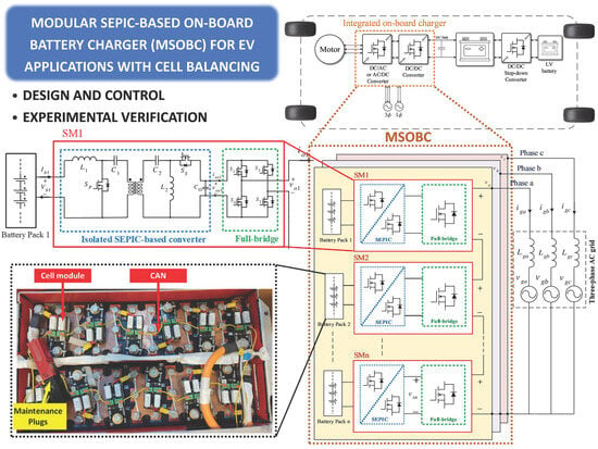
Design and Control of a Modular Integrated On-Board Battery Charger for EV Applications with Cell Balancing

School of Engineering, Lancaster University, Lancaster LA1 4YW, UK
*
Author to whom correspondence should be addressed.
Batteries 2024, 10(1), 17; https://doi.org/10.3390/batteries10010017
Submission received: 16 November 2023 / Revised: 13 December 2023 / Accepted: 28 December 2023 / Published: 2 January 2024
(This article belongs to the Special Issue Advances in Battery Electric Vehicles)

Abstract

:
This paper presents operation and control systems for a new modular on-board charger (OBC) based on a SEPIC converter (MSOBC) for electric vehicle (EV) applications. The MSOBC aims to modularise the battery units in the energy storage system of the EV to provide better safety and improved operation. This is mainly achieved by reducing the voltage of the battery packs without sacrificing the performance required by the HV system. The proposed MSOBC is an integrated OBC which can operate the EV during traction and braking, as well as charge the battery units. The MSOBC is composed of several submodules consisting of a full-bridge voltage source converter connected on the ac side and SEPIC converter installed on the battery side. The SEPIC converter controls the battery segments with a continuous current because it has an input inductor which can smooth the battery’s currents without the need for large electrolytic capacitors. The isolated version of the SEPIC converter is employed to enhance the system’s safety by providing galvanic isolation between the batteries and the ac output side. This paper presents the necessary control loops to ensure the optimal operation of the EV with the MSOBC in terms of charge and temperature balance without disturbing the required modes of operation. The mathematical analyses in this paper are validated using a full-scale EV controlled by TMS320F28335 DSP.

Graphical Abstract

1. Introduction

There are international diligent efforts aimed at promoting electric vehicles (EVs) as a viable alternative for vehicles powered by internal combustion engines (ICEs). Ratified by several European countries, the Green Deal has an ambitious target to achieve carbon neutrality in the transport sector by 2050 [1,2]. However, there is still clear uncertainty about the effect of the electrification of the transport sector on the electric grid as well as the employability of automotive engineers and technicians, which should be considered carefully [3]. There is agreement between the field’s experts that the electrification of the transport sector may significantly lower the impact of climate change on the electric grid as well as the employability of automotive engineers and technicians [4]. Given the little time left until 2050 and the considerable dangers involved in this process, a number of elements should be taken into consideration to combat climate change and make this transition effective [1,2].
In general, the high-voltage (HV) battery is the main obstacle to EVs’ development to meet the transition target for several reasons. Being the vehicle’s primary source of propulsion energy, the HV battery accounts for a considerable amount of its bulk, volume, and expense. In addition, the HV battery is the most hazardous component of EVs, requiring expert staff to handle it during maintenance, troubleshooting, and assembly procedures [5,6,7]. Users’ confidence in switching from ICE vehicles to EVs is lowered by an obvious competence gap among automotive counterparts in the field of HV battery assembly and maintenance [8,9].
Lithium-ion batteries are typically utilised as energy storage components in the HV battery box in EVs thanks to their extended life cycle and high power-density [10]. To ensure the safe, reliable, and efficient use of batteries in EVs, a battery management system (BMS) is integrated into the battery system [11]. A BMS has several features to continuously monitor and control the different operation states of the batteries, including cell monitoring (i.e., voltage, current, and temperature), state of health (SOH) and state of charge (SoC) estimation, cell balancing in case of any voltage mismatches, thermal management (heat dissipation), rate of charge control, and battery safety and protection against short circuit and overcharge/overdischarge [12].
Figure 1 shows the main EV powertrain architecture with the HV battery being in the middle of the propulsion system. During the normal driving mode, the power flows from the HV battery to the dc/ac inverter, which controls the electrical motor [13,14].
The low-voltage (LV) battery is responsible for the operation of the BMS and other control circuits which are not within the scope of this paper.
During the charging mode, the HV battery can be charged using two different methods [15]. The faster method involves using an off-board DC charger which is often supplied from a three-phase supply [16]. Using an on-board charger (OBC) within the car is the alternative way to charge the HV battery [17,18]. This allows the EV battery to be charged from single-phase or three-phase power supplies. The existence of a high-power OBC inside the EV will increase the customers’ confidence about the ability to charge their EV easily at various locations rather than relying solely on specialised EV charging stations that might not be always available nearby when the EV needs to be charged [19]. The OBC typically consists of two-stage power converters that serve two primary purposes, as seen in Figure 1. The initial step of ac/dc rectification involves converting grid-supplied AC power into DC power while maintaining grid-side power quality. The second stage functions as a dc/dc converter since it is in charge of injecting the required current into the HV battery to charge it [17,18]. To guarantee that the battery is electrically isolated from the ac grid, one of the stages must have some form of galvanic isolation [19,20]. Figure 1b illustrates the integrated OBC, which combines power electronic converters into a single architecture to operate the EV during braking, driving, and charging modes. This will significantly increase the use of power electronic components, resulting in a reduction in size, weight, and space. This will unavoidably add to the overall system’s complexity in terms of control during driving and balancing during charging [17,18].
The integrated OBC configurations are bidirectional systems where the electrical power can flow from the input to the output sides in both directions [21]. The development of bidirectional power converters plays a major role in the progress of EV chargers [22]. The major goals in designing OBC chargers are boosting efficiency by cutting down on power losses, increasing the converter’s energy density, and reducing the complexity of the operation.
Bidirectional power electronic converters employ semiconductor active transistors with passive diodes to allow the currents to flow in both directions [21,22]. This implies that more wire and circuitry will be needed for the gate driver boards of the transistors [23]. In addition, the bidirectional converters require suitable control techniques to facilitate bidirectional power flow [23]. A common issue with bidirectional converters is that excessive voltage across the transistors and current strains through the transistors can cause several operational issues as well as recurrent failures [24,25].
Modular OBCs, which divide the power converter into multiple smaller ones, may resolve the problem of increased stress [26,27]. Additionally, the HV battery can be restructured into battery segments at lower voltages, allowing small converters to be linked to battery segments and drastically lowering the input voltage and associated dangers. Additionally, the modular design offers a fair level of redundancy in the event of a tractive system partial failure and gives the option to scale the EV power up if needed in the future [26]. Although the modular method has been around for a while in renewable energy systems (RESs), it has not been extensively embraced in EV applications [27].
This paper proposes a novel modular OBC based on a SEPIC converter (MSOBC), which is shown in Figure 2, where a smaller number of less than 100V segments of the HV battery are connected to SEPIC converters followed by cascaded H-bridge converters. For the battery-side converters, both the SEPIC and Cuk converters are good candidates for the modular converter because they have a continuous current at their input side, and they allow for high-frequency (HF) transformer isolation [28,29]. The outputs of these converters are connected in series to boost the voltage up again to match the motor’s voltage.
The selected SEPIC converter in the proposed MSOBC allows power flow to occur during the following modes:
  • Normal driving mode, from individual battery segments to the electrical motor;
  • Regenerative braking mode, from the vehicle’s kinetic energy to charge the battery segments via the electrical generator;
  • Charging mode, from the AC grid to the battery segments.
To prevent overvoltage, undervoltage, and thermal runaway, it is essential to balance the battery packs of modular converters using the BMS. This will guarantee a fair distribution of current and, consequently, SOC amongst the various battery packs. As a result, this paper will discuss the battery balancing system of the proposed MSOBC structure to ensure this, and therefore it will focus on the third power flow function mentioned earlier.
Also, this paper presents a decentralised control system to ensure that the SOC of the battery segments and hence their voltages will be maintained in the permitted range during the EV driving and charging modes. This study presents a mathematical analysis of the proposed MSOBC as well as experiments using a full-scale test bench composed of battery segments with a total capacity of 5.7 kWh and an 80 kW permanent magnet synchronous machine (PMSM) controlled by a TMS320F28335 Digital Signal Processor.

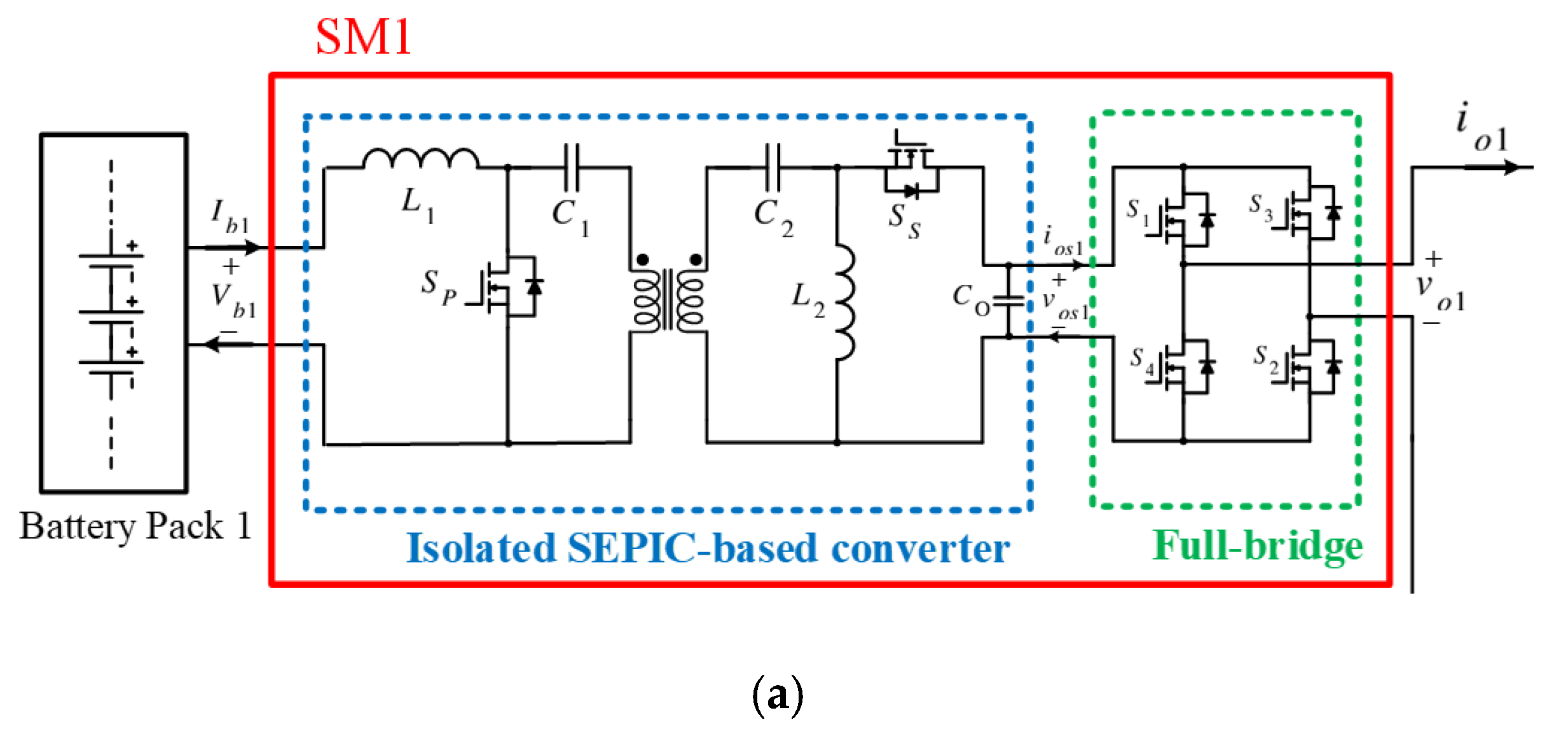
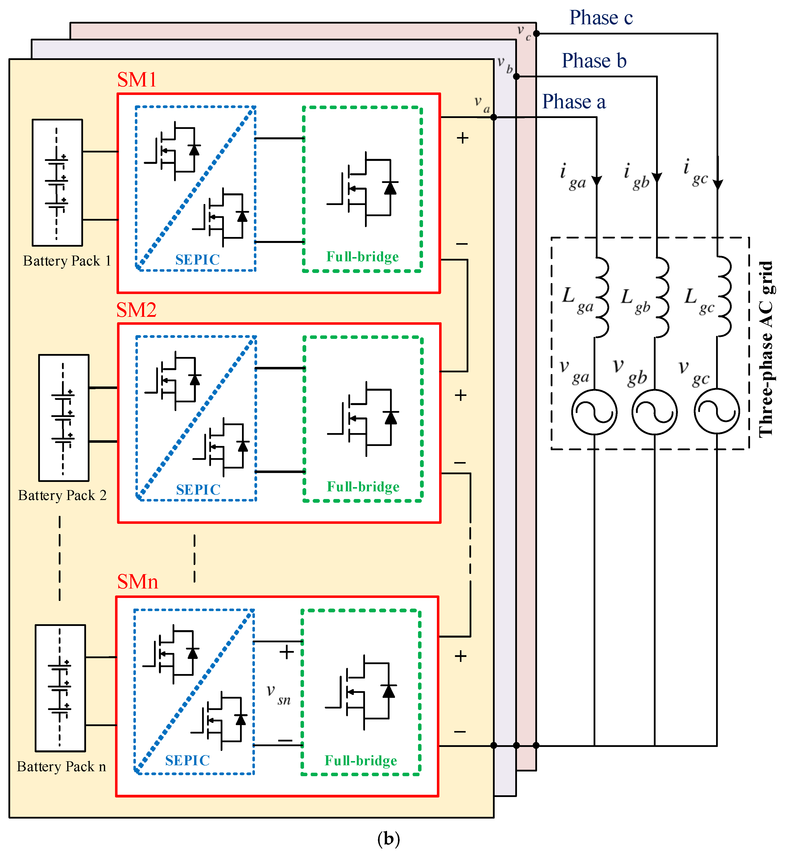
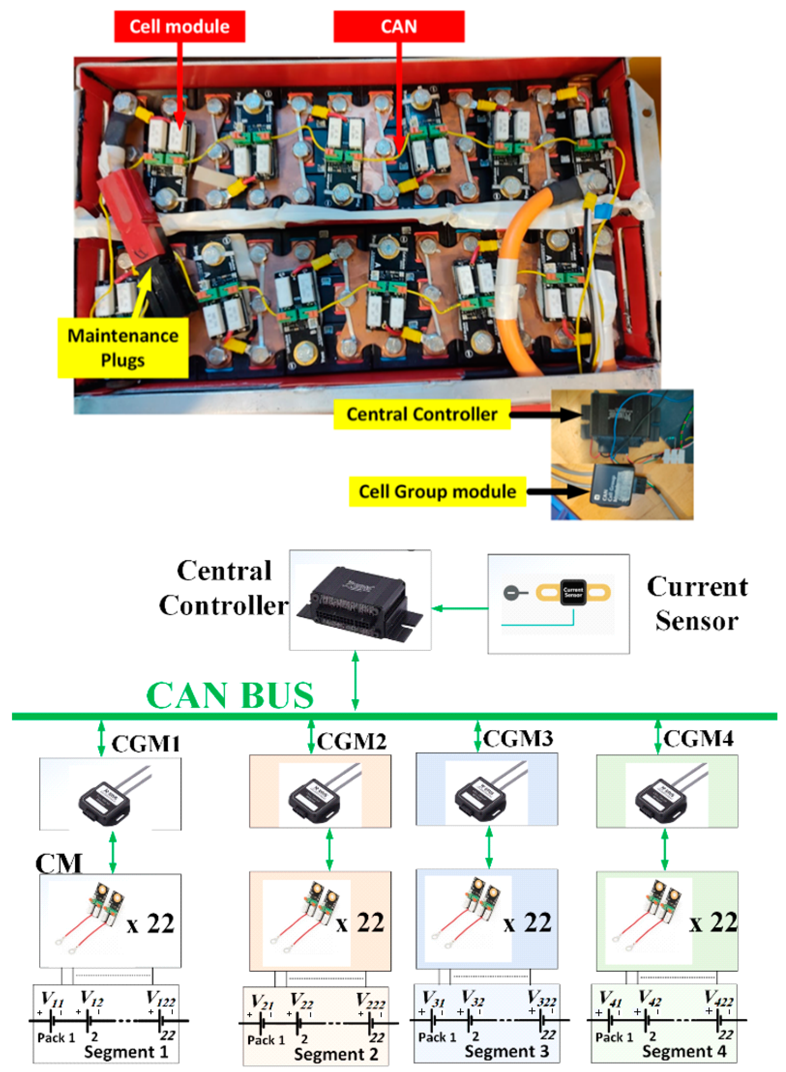
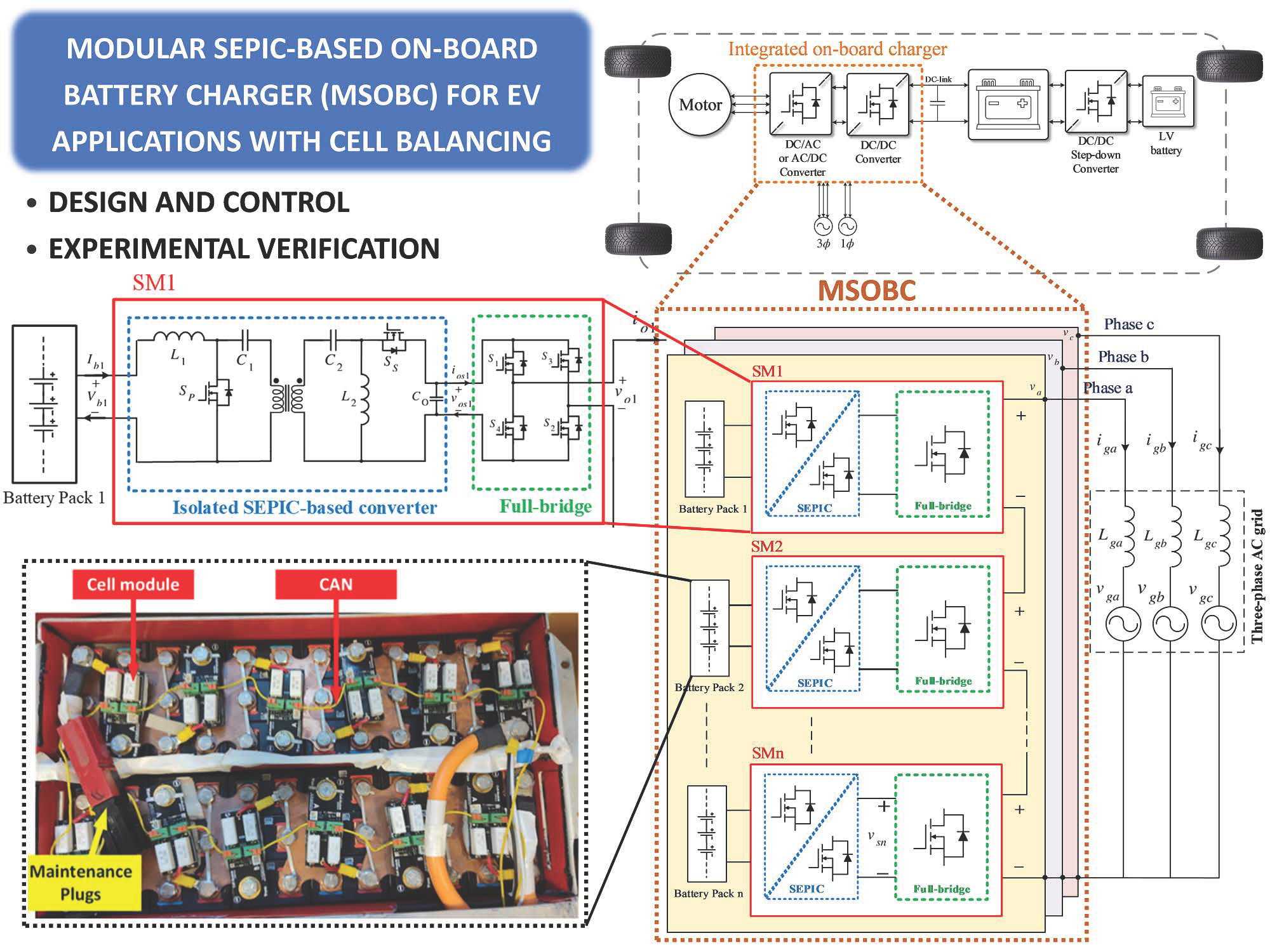
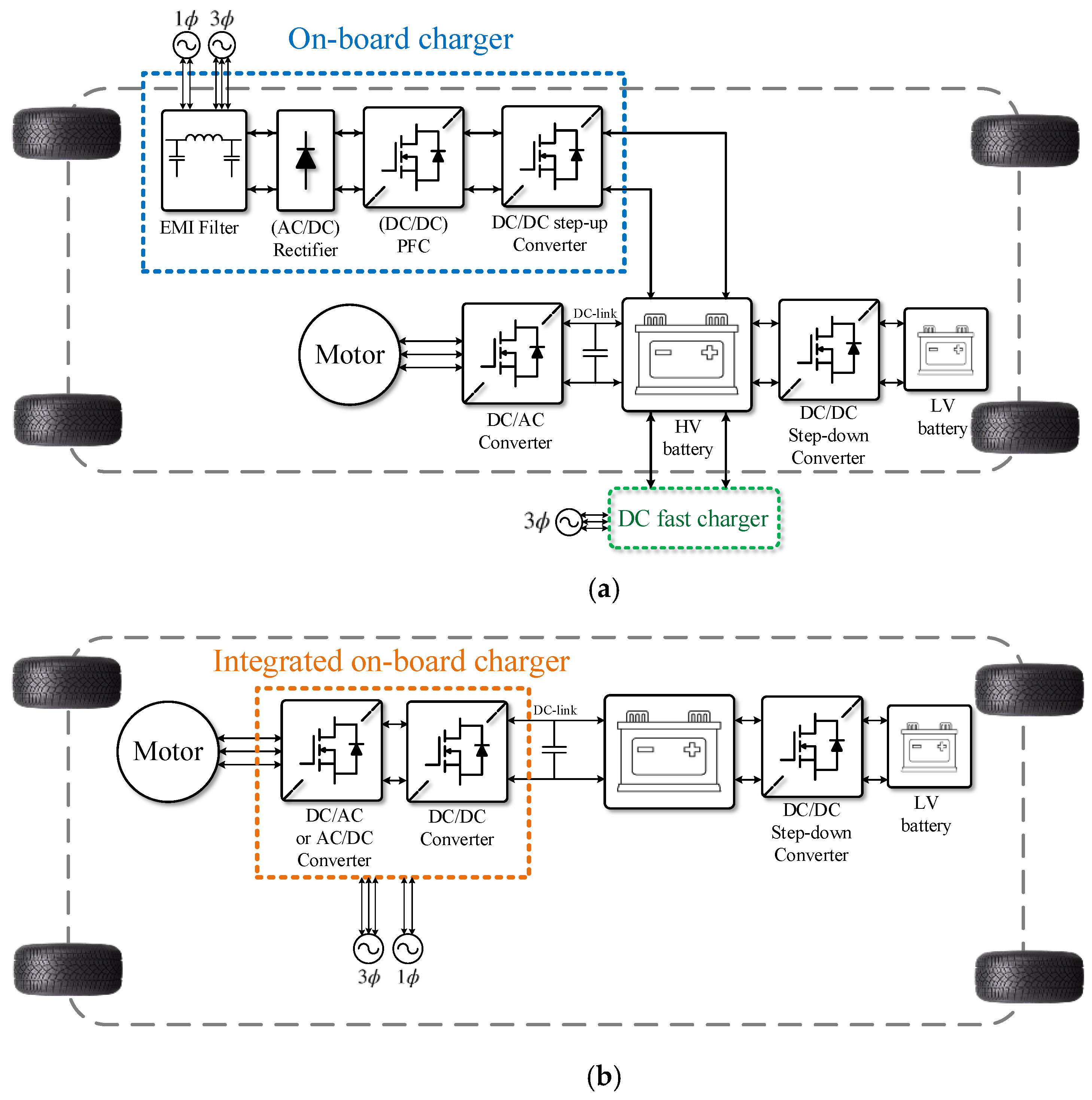
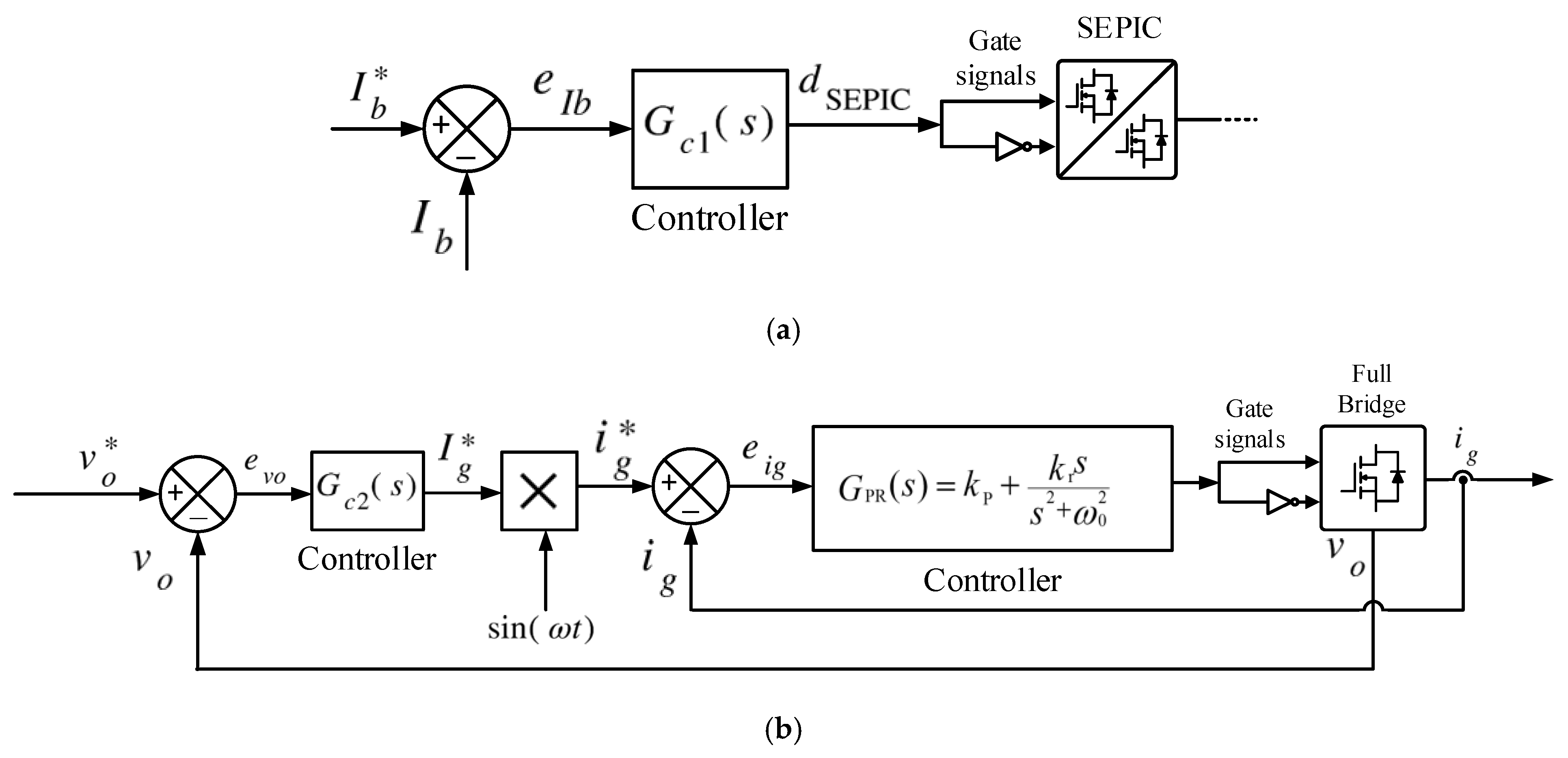
2. Description of the Proposed Integrated Modular OBC
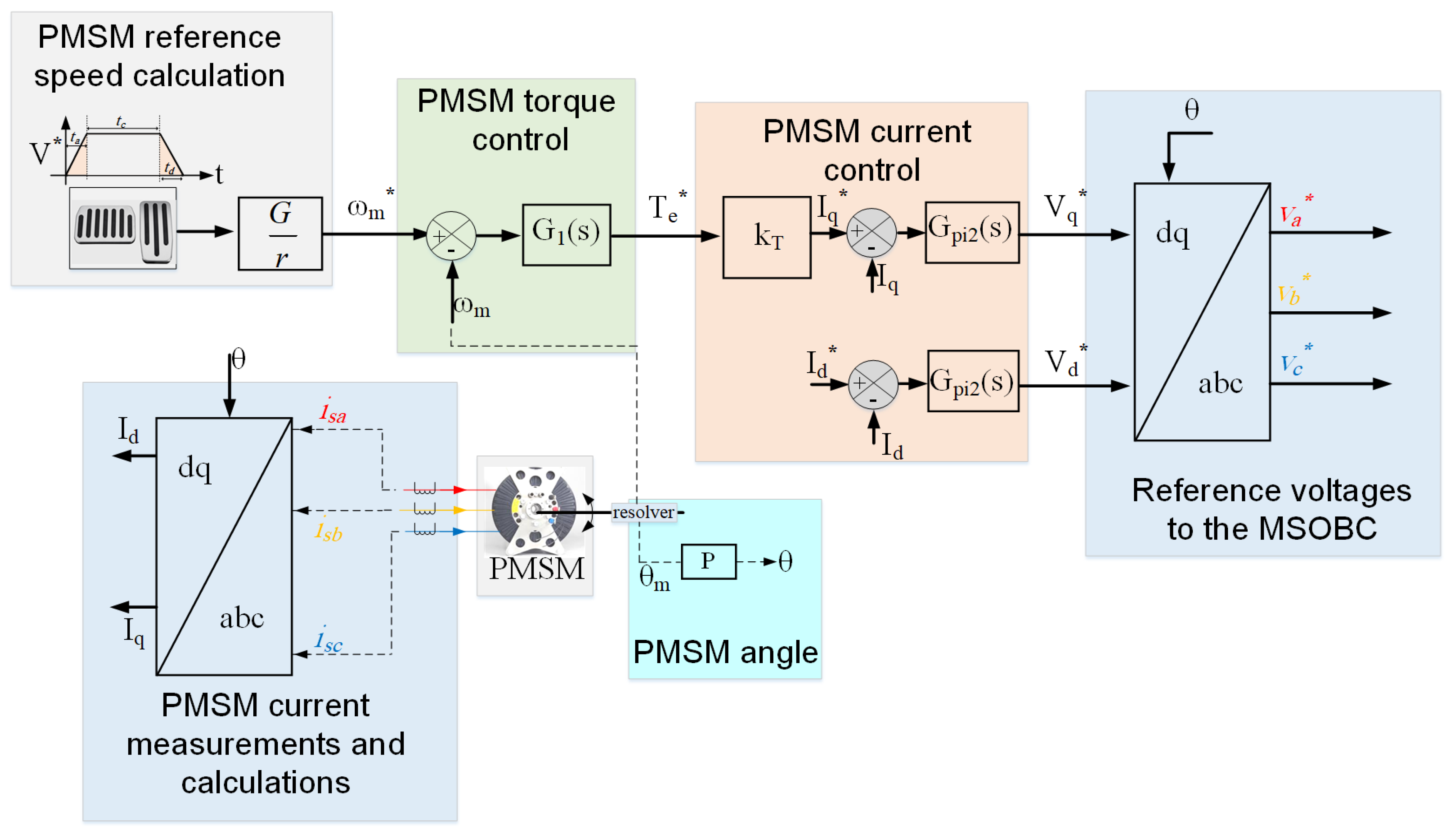
The single-phase and three-phase layout of the proposed integrated MSOBC is shown in Figure 1, where a battery pack is connected to an isolated SEPIC converter followed by a full-bridge converter in each submodule (SM) to regulate the battery current in case of charging or discharging. The battery pack is composed of ns lithium-ion (Li-ion) batteries in series and np in parallel. Because of its input inductor, the SEPIC converter will draw a constant current from the battery. The output capacitor of the SEPIC converter will filter the output voltage for the next stage of the H-bridge. As the SEPIC converter has an embedded high-frequency transformer (HFT), it can provide a sort of galvanic isolation between the battery pack and the motor in case of driving and the utility grid in case of charging.
The SEPIC converter is then connected to an H-bridge converter to generate the required ac voltage. The two-stage converter SM is bidirectional to allow the energy to flow from the battery to the motor during driving and from the grid/vehicle to the battery during charging/regeneration. It is worth noting that during charging, when the power flow is reversed, the SEPIC converter can be seen and controlled as a Zeta converter.
Each phase of the MSOBC is composed of a number of m SMs and their outputs are connected in series. In this configuration, the motor’s voltage can be made much higher than the battery segment’s voltage, where the voltage and current stresses are shared among the devices of the SEPIC and H-bridge converters. The MSOBC can continue functioning in case of partial failure in either the battery pack or the semiconductor devices. This is unlike the conventional integrated OBCs where any failure in these subsystems will lead to a complete shutdown of the EV until the maintenance takes place. To show the main operation of the MSOBC, an EV with the specifications in Table 1 was used.

2.1. PMSM Model

Equations (1)–(3) show the dq-synchronous frame model, which will be used to control the PMSM in this paper. In this system, the d-axis is aligned with the rotor’s permanent magnet, while axes a, b, and c indicate the direction of the three-phase windings’ flux vectors. The angular displacement θ is measured by the resolver of the PMSM. Consequently, the PMSM model can be expressed as follows:
V d V q = R s 0 0 R s I d I q + L d 0 0 L q d d t I d I q + ω 0 L q L d 0 I d I q + Φ r
ω = P ω m
T e = 3 2 P Φ r I q
where Vd and Vq are the stator voltages expressed in dq coordinates, Id and Iq are the stator dq currents, ω is the electrical frequency of the stator voltage, ωm is the rotational speed of the motor, G is the gearbox’s ratio, Φr is the flux linkage of the PMSM, Rs is the stator windings’ resistance, Ld and Lq are the dq components of the stator windings’ inductance, Te is the developed electromechanical torque, and P is the number of pairs of poles.

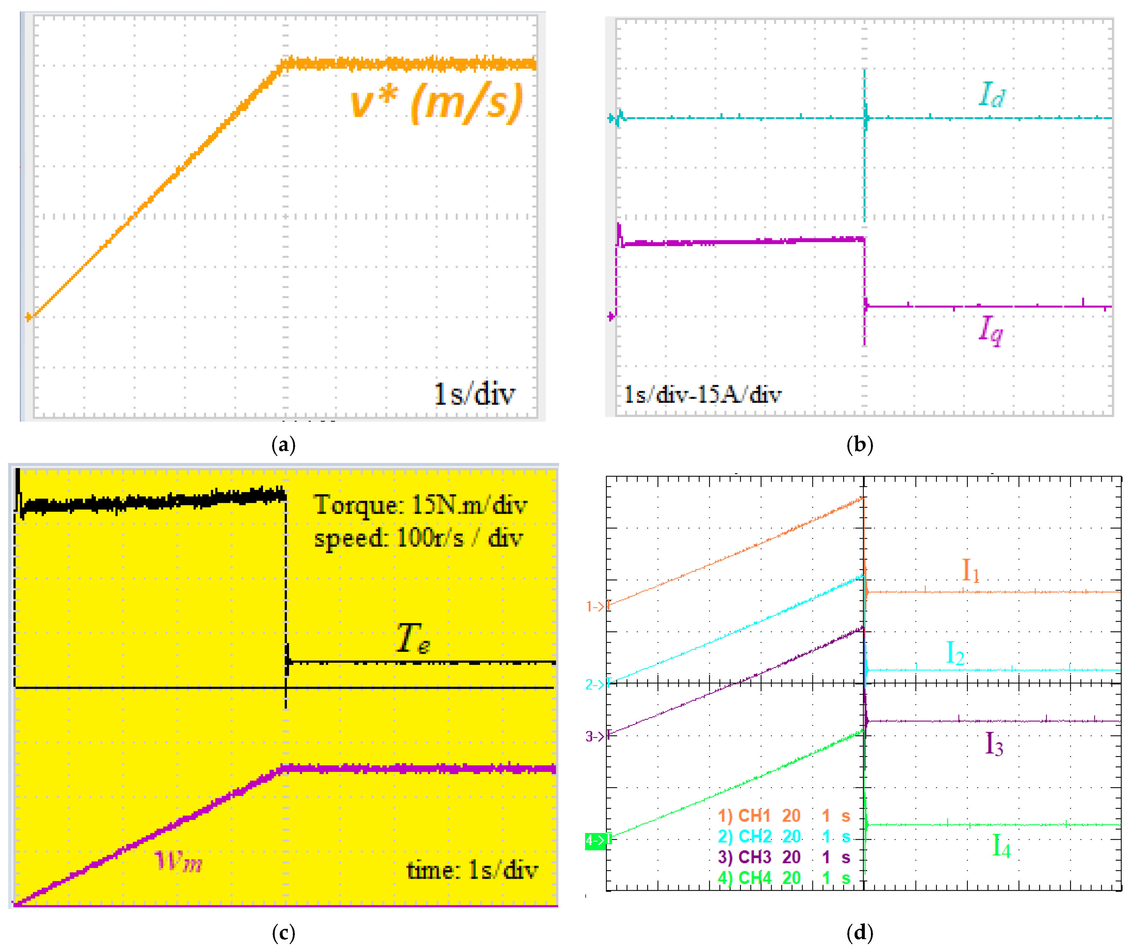
2.2. Driving Mode of the EV with the MSOBC
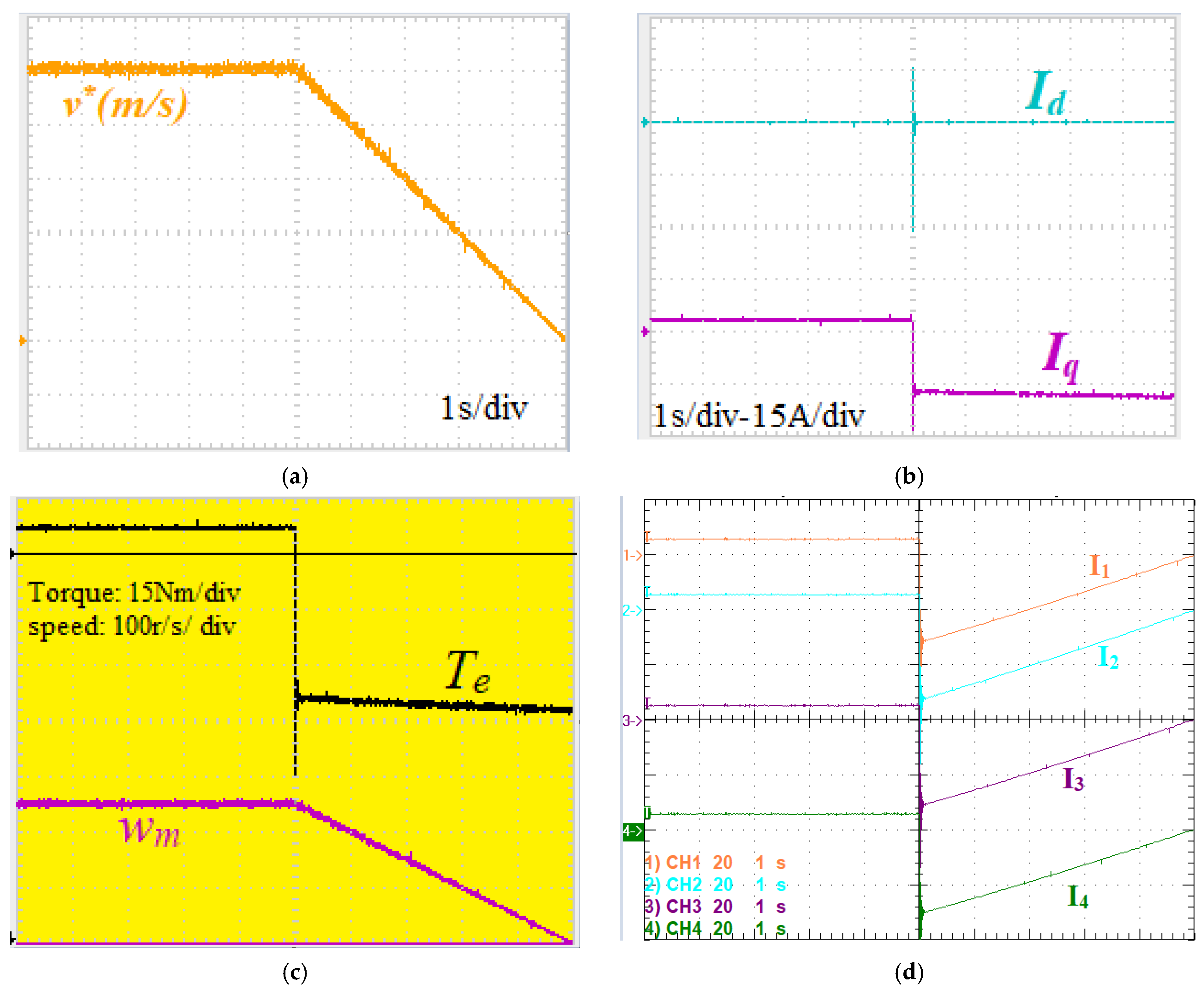
Figure 3 shows the main structure of the control used in the control system to operate and test the MSOBC when the EV has the specifications listed in Table 1. The linear speed demand v* is sensed by the accelerating pedals, and hence the associated rotational motor speed ωm* is calculated using the known gear ratio and wheel size.
The speed is then controlled using the developed PMSM torque Te. As it is not simple to install torque sensors, another current control loop is employed to control Te indirectly using the q-axis current Iq, while the d-axis current Id is kept at zero. Finally, the currents of the PMSM are controlled by the three-phase voltage input which is generated by the MSOBC. To show the required overall voltages and current demanded by the MSOBC during the normal driving mode, the experiments in Figure 4 will be explained.
Figure 4a shows the velocity profile of the EV when the speed command v* increases linearly from zero to the top speed of 30 m/s (=108 km/h) in 5 s. As shown in Figure 4b, the rotational speed of the PMSM increases according to the developed torque Te, which is kept constant at around 52.5 N·m. Meanwhile, the current controllers keep Iq = 22.5 A and Id = 0 A. Both the battery segments’ currents and the PMSM back emf voltages increase linearly following the EV power. Then, the EV keeps running at the top speed for another 5 s. The required torque is relaxed and drops to 7.5 N·m, leading the current Iq component to also drop to 3.2 A. Because the EV power is constant, the currents absorbed from the battery segments are kept at around 3 A.

2.3. Braking Mode

Using the same control system as in Figure 3, the MSOBC can regenerate the kinetic energy of the EV and send it back to the battery segments. This regenerative braking is reported to save about 10% of the battery capacity if activated. By controlling the PMSM currents, the developed torque Te* can be reversed and hence the electric machine will operate as a permanent magnet synchronous generator (PMSG). Figure 5a shows the speed command to stop the car in 5 s. Figure 5c shows the negative torque of the PMSG which is performed by reversing the q-axis current Iq at around 16 A, as shown in Figure 5b. The battery segments’ currents in Figure 5d are reversed because the battery cells are being charged.

2.4. Charging Mode

The integrated MSOBC is able to charge the battery packs if the ac terminals are connected to the ac utility grid. Figure 6 shows the control scheme for the charging function. As the main goal is to control the charging power of the battery packs, the first control loop is set by comparing the reference battery current to the actual current which is measured using a hall effect sensor, as mentioned in Table 1. The error current signal is fed to a proportional–integral (PI) controller which regulates the duty cycle ratio of the SEPIC converter (dSEPIC). Another dual-loop control scheme is designed to regulate the dc-link voltage between the SEPIC converter and the full-bridge converter Vdc. The inner loop of this controller regulates the ac grid current ig to operate at a unity power factor with respect to the utility grid using a proportional resonant (PR) controller.
Figure 7 shows the charging operation using the MSOBC over a period of 100 ms, which is equivalent to 10 grid cycles. The battery currents of the battery segments in phase a are shown in Figure 7a. Similarly, the dc-link voltages between the SEPIC and the full-bridge converters in phase a are shown in Figure 7b. The total input grid voltage and current of phase a are shown together in Figure 7c. To show the complete charging process over the full charging period, Figure 7d shows the current of the first battery segment in phase a with its voltage when the SoC of the batteries is increased from 20% to 100%.

3. Problem of Unbalanced Battery Packs

Although the battery segments are drawn separately in Figure 2, they are close to each other physically in the battery box of the EV. As shown in Figure 8, the segments will exchange their heat together through conduction and convection. The thermal connection will be asymmetrical with the battery packs, which are close to the insulation material of the battery box; these are usually manufactured using FR-4 insulating materials. This will lead to non-uniform distribution of the temperature among the battery packs. If the cooling system does not release heat efficiently from the surrounding, there will be a risk of thermal runaway of the battery cells, which is agreed to be a major concern in EVs.
The voltage of the Li-ion battery varies in a narrow range between 2.5 for 0% SoC and 4.2 V for 100% SoC. The power and hence the heat generated by the battery pack mainly depend on the charging or discharging current and the SoC. The initial SoC, where each battery pack started its operation, determines the rate of increasing and decreasing the charge capacity.
It is worth noting that the conducted tests and the experimental results of the MSOBC shown earlier in Figure 7 are obtained when the battery packs start from very close SoCs. However, the performance will differ if the battery cells have a large mismatch in their initial SoCs. Figure 9 shows the experimental testing for the three series cells charged and discharged by a current 1C. In the first test, as shown in Figure 9a, the cells start charging with 20A from almost the same SoC. It can be seen that the SoC will stay close during both the charging and discharging processes. In Figure 9b, the cells start with a 10% SoC mismatch. In this case, the power and hence the energy received and released by the cells will be different, which means that the temperature distribution will be different as well.
The employed Li8P25RT battery packs have internal Zener diodes which can measure the temperature of battery cells. These Zener diodes were used to monitor the batteries’ temperatures as shown in Figure 10, which demonstrates the effect of SoC variation on the batteries’ temperatures. It can be seen that the batteries will have different temperature distribution which will depend on the power distribution and the thermal heat transfer, which is affected by cooling and insulation. The main drawback of the unbalanced temperature distribution is that the cells which operate at a higher temperature will age quicker than the others, which will lead to a non-uniform distribution in the capacity. This operation should be avoided to ensure proper operation for the balancing system and other functions in EVs.

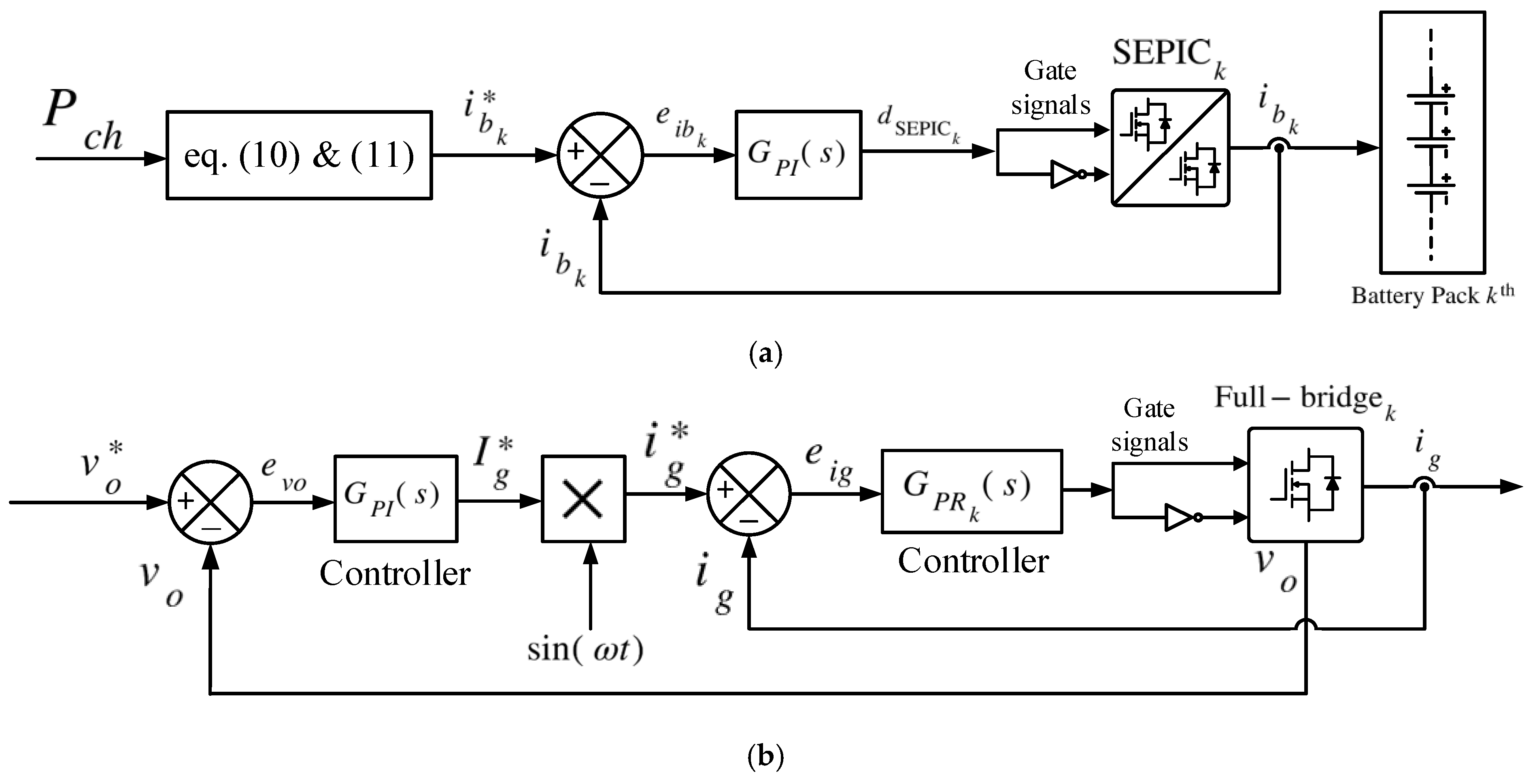
4. Charging the Battery Packs of the MSOBC

In light of the previous discussion, the proposed MSOBC can be controlled to provide online balancing of the battery packs to ensure that the different SoCs and temperatures are in the acceptable range. As a general rule, the battery packs’ SoCs and temperatures are directly proportional to the charging current, and therefore it is used as the control element. However, the relation between the SoC and the terminal voltage depends on other factors such as the state of health (SoH), aging, internal resistance, and life cycle. However, the battery’s SoC will be estimated from the terminal voltage in the next experiments for the sake of simplicity.
The MSOBC structure in Figure 2 shows that there are two converter stages in each submodule which can be controlled separately. The first grid-side stage is controlled by the full-bridge converters that act as ac/dc rectifiers in the charging mode, while the battery-side stage is controlled by the SEPIC isolated converter which operates as a dc/dc charger to regulate the battery’s current.
The input voltage of the ac/dc rectifiers will be defined as vgk, where k denotes the number of the battery segment. Neglecting the voltage drop across the grid filter, the input power to the kth rectifier is expressed as follows:
P g k = v g k ( t ) i g ( t )
The charging power of the kth battery segment is as follows:
P b k = η f b η s v g k ( t ) i g ( t ) = V b k I b k
where ηfb is the efficiency of the full-bridge rectifier and ηs is the efficiency of the SEPIC converter.
If the voltage drop across the grid-side filter is ignored, the total voltage of the series-connected dc/ac rectifiers in each phase can be written as follows:
k = 1 n v g k ( t ) v g ( t )
Because the same grid current ig flows in the dc/ac rectifiers, vgk can be calculated from the following:
v g k ( t ) V b k I b k i = 1 n V b i I b i v g ( t )
Equation (7) shows that the charging power of each battery segment can be controlled by the input voltage and sent to the full-bridge converter associated with the segment. The results presented earlier in Figure 7 were obtained when the voltages and the charging currents of the four employed battery segments were equal. Therefore, both the input voltages of the rectifiers and the dc-link voltages were shared equally across the different submodules. The next subsections will present the operation of the MSOBC when there is an uneven distribution of SoC and temperature.

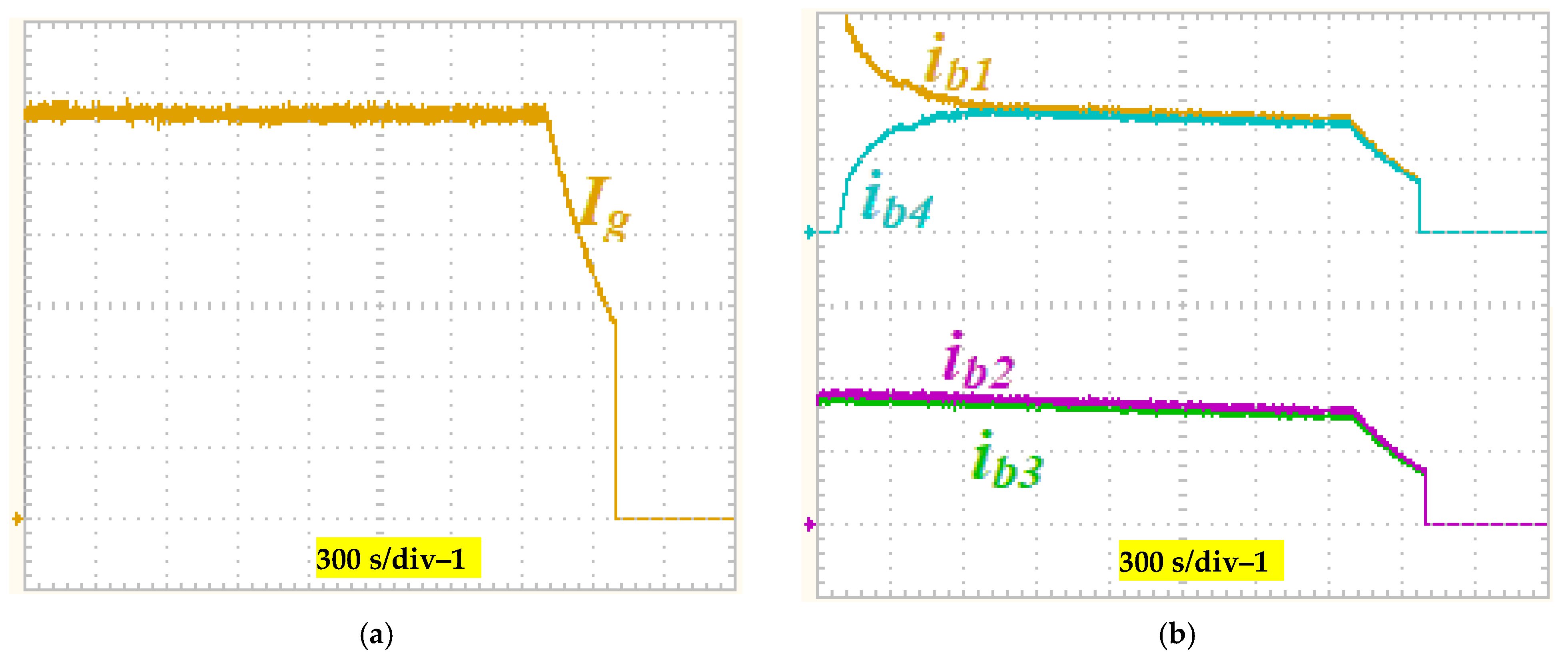
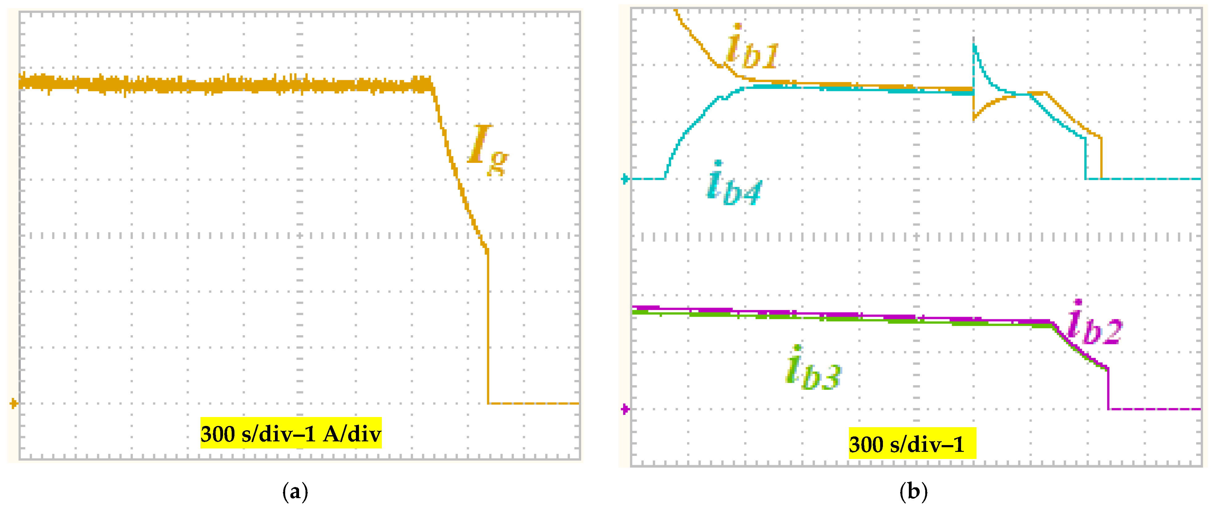
4.1. Charging Battery Packs with Non-Uniform SoCs

The control loops of each submodule in the three phases are split per each battery pack, as shown in Figure 11. Accordingly, the reference charging currents of the batteries will be determined based on the segments’ voltages. The total charging power of the MSOBC is set to Pch and can be expressed as follows:
P c h v g a i g a + v g b i g b + v g c i g c
Assuming a balanced three-phase operation, the power delivered to the battery segments of phase a is calculated from the following:
P b a η f b η s P c h 3 = n V ¯ b × I ¯ b
where V b ¯ and I b ¯ are the average voltage and charging current of the battery segments. The average battery voltage can be calculated from the measured individual battery voltages as follows:
V ¯ b = i = 1 n V b i n
To balance the battery packs, their charging current should be controlled at Ibk, which is inversely proportional to the SoC. Thus, this current is calculated from the following:
I b k = η f b η s P c h 3 n V b k
To show the charging process of the MSOBC using the modular control system in Figure 11, the experimental tests in Figure 12 are conducted when the battery packs start with different voltages and SoCs. The first segment starts from SoC = 35%, the second and third segments start from an SoC = 28%, and the fourth segment starts from SoC = 20%. Because the time-span of the charging process is long, Figure 12a shows the magnitude of the phase a grid current needed to deliver 3 kW. The charging currents of the segments in phase a will be controlled to balance the packs based on Equations (8)–(11), as shown in Figure 12b. The fourth segment drew the highest current to balance fast. The dc-link voltages are shown in Figure 12c, which shows that the dc-link voltages are close to each other because the MSOBC delivers equal power to each battery segment even if their voltages are not equal. Figure 12d shows the change in battery segment voltages throughout the charging time. Figure 12e shows the temperatures of the battery segments of phase a.

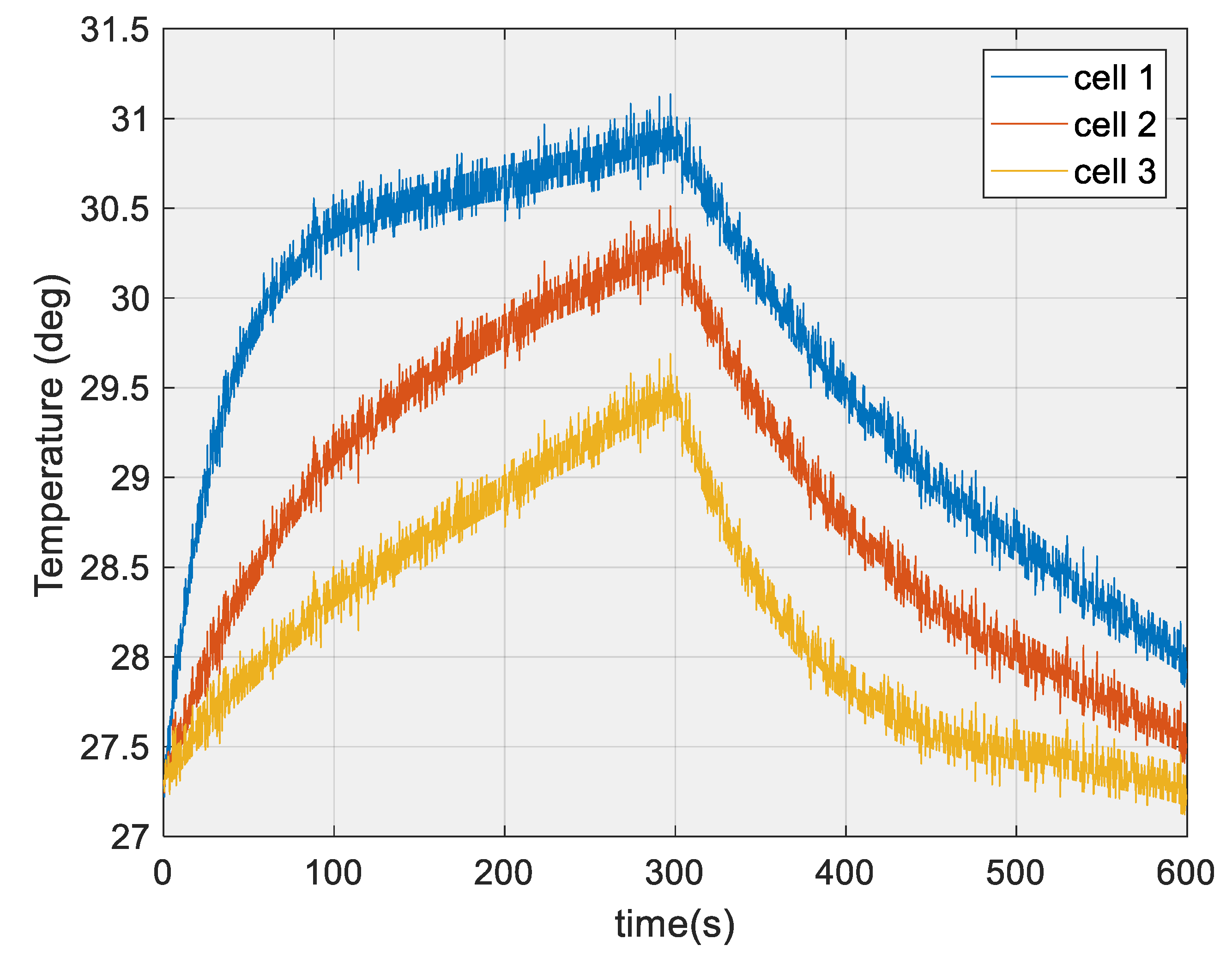
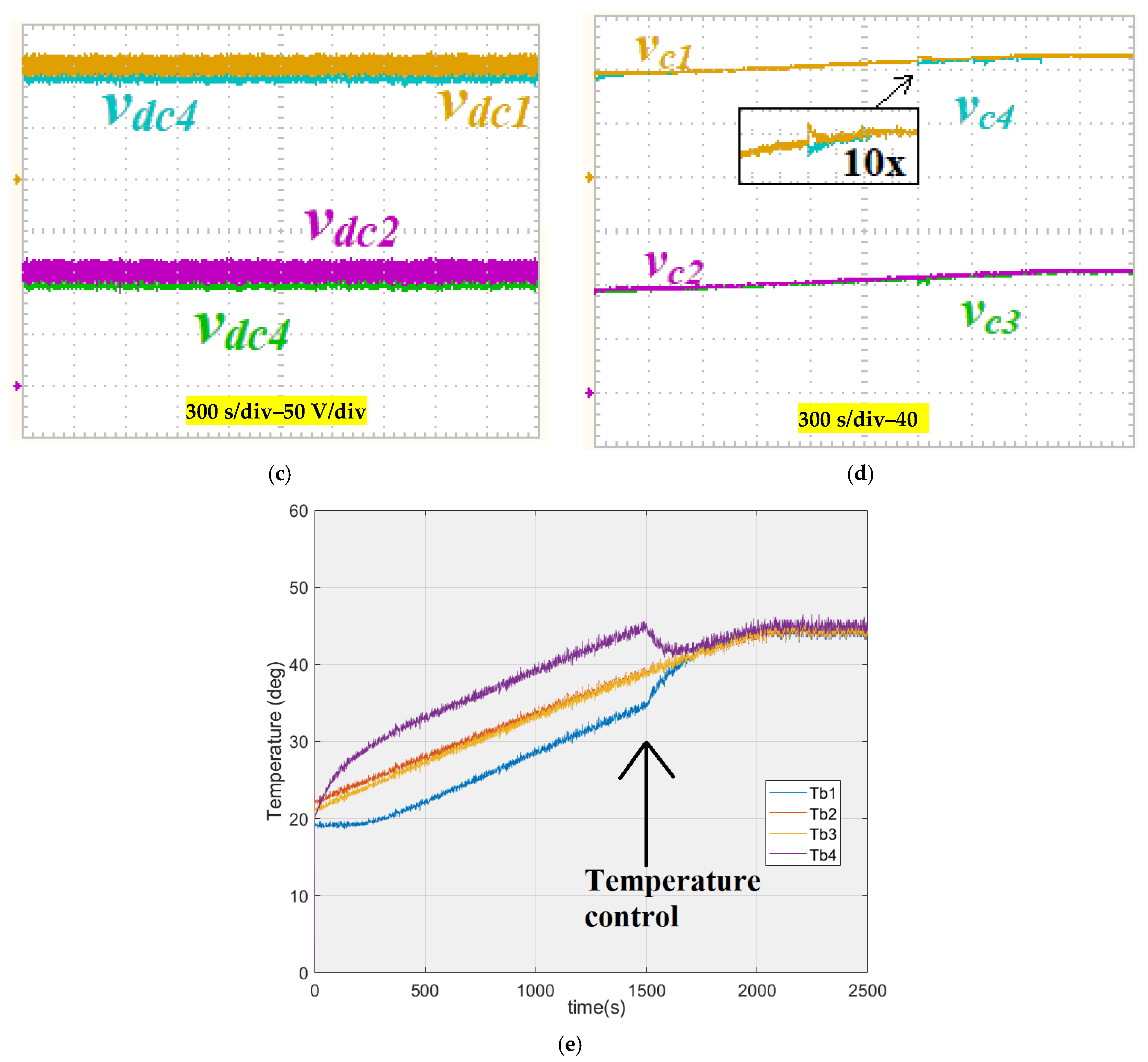
4.2. Charging Battery Packs According to Temperature

In the previous subsection, the charging currents of the battery segments were controlled to balance the SoC as fast as possible. Accordingly, the temperatures of the battery packs were not considered, and some battery packs may have become hotter than others. Thus, the battery packs may need to be balanced in terms of their temperatures rather than their SoCs and voltages. If this is the case, the reference charging current can be recalculated based on the temperature calculations. The average temperature of the battery segments is calculated from the following:
T ¯ b = i = 1 n T b i n
where Tbk is the temperature of the kth battery segment. To balance the battery packs’ temperatures, their charging current should be controlled at Ibk, as follows:
I b k = T ¯ b T b k I ¯ b
The results in Figure 13 show the charging process of the MSOBC when the control system is targeted to balance the temperatures of the battery packs. At the beginning, the batteries begin to charge by balancing their SoCs as in the previous mode. However, when the difference between the first and the fourth battery segment reaches a certain limit, the temperature control mode is activated to balance the temperature of the batteries. The balancing period takes approximately 5 min, and in which time the battery pack temperatures all become in the acceptable range of 5% mismatch. The experimental tests are conducted when the battery packs begin from different temperatures, which are monitored using the measurement Zener diodes of the Li8P25RT battery modules. Figure 13a shows the phase a grid current which is kept constant through the process to deliver around 3 kW to the three-phase system. The charging currents of the segments in phase a are controlled as shown in Figure 13b to balance the packs based on their measured temperatures after t = 1500s. Because the charging powers are not distributed uniformly in this mode, the values of the dc-link voltages of the submodules in Figure 13c are not equal. Figure 13d shows the change in battery segment voltages throughout the charging time. Finally, Figure 13e shows the temperatures of the battery segments of phase a.

5. Conclusions

A new modular integrated OBC for electric vehicle (EV) applications has been presented in this paper, with bidirectional isolated SEPIC converters on the dc side (battery packs) and bidirectional full-bridge converters on the ac side (ac grid or PMSM machine). The proposed MSOBC converter shares the voltage and current stresses across decentralised submodules to provide more redundancy, improve the reliability, and enhance the safety of the system. The batteries in the HV systems are split in segments and connected to the submodules with reduced voltages per segment. Although the modular structure is built using several semiconductor switches, the rating of these switches can be lowered and therefore their cost and reliance on resistances can be significantly reduced. This paper has presented a proper control system to ensure optimal operation of the whole system during normal driving mode, regenerative braking, and charging. The proposed controllers are capable of balancing the battery packs based on their SoCs and their temperatures. The experimental results using an EV racing car with an 80 kW PMSM and 5.7 kWh battery segments verify that, even with varied initial SoCs or temperatures, the MSOBC was able to retrieve, balance, and supply the required power to the battery segments. Using the SoC balancing method, the controller fixed a mismatch of 15% in the SoC of the batteries by controlling the charging current to less than 2%. During this operation, the difference between the hottest and coldest cell was kept at 10 °C. Using the temperature balancing method, the controller was able to eliminate the mismatch in the temperature within 5 min.

Author Contributions

Conceptualization, F.N.E. and A.D.; methodology, F.N.E. and A.D.; software, F.N.E. and A.D.; validation, F.N.E. and A.D.; formal analysis, F.N.E. and A.D.; investigation, F.N.E., A.D. and X.M.; resources, A.D. and X.M.; data curation, F.N.E. and A.D.; writing-original draft preparation, F.N.E. and A.D.; writing-review and editing, A.D. and X.M.; visualization, A.D. and X.M.; supervision, A.D. and X.M.; project administration, A.D. and X.M.; funding acquisition, A.D. and X.M. All authors have read and agreed to the published version of the manuscript.

Funding

This research received no external funding.

Data Availability Statement

The data presented in this study are available on request from the corresponding author. The data are not publicly available due to privacy.

Conflicts of Interest

The authors declare no conflict of interest.

References

  1. The European Green Deal. Available online: https://commission.europa.eu/strategy-and-policy/priorities-2019-2024/european-green-deal_en (accessed on 25 October 2023).
  2. Szumska, E.M. Electric Vehicle Charging Infrastructure along Highways in the EU. Energies 2023, 16, 895. [Google Scholar] [CrossRef]
  3. Bayani, R.; Soofi, A.F.; Waseem, M.; Manshadi, S.D. Impact of Transportation Electrification on the Electricity Grid—A Review. Vehicles 2022, 4, 1042–1079. [Google Scholar] [CrossRef]
  4. Tamba, M.; Krause, J.; Weitzel, M.; Ioan, R.; Duboz, L.; Grosso, M.; Vandyck, T. Economy-wide impacts of road transport electrification in the EU. Technol. Forecast. Soc. Chang. 2022, 182, 121803. [Google Scholar] [CrossRef] [PubMed]
  5. Chen, S.; Dai, F.; Cai, M. Opportunities and challenges of high-energy lithium metal batteries for electric vehicle applications. ACS Energy Lett. 2020, 5, 3140–3151. [Google Scholar] [CrossRef]
  6. Pradhan, R.; Keshmiri, N.; Emadi, A. On-Board Chargers for High-Voltage Electric Vehicle Powertrains: Future Trends and Challenges. IEEE Open J. Power Electron. 2023, 4, 189–207. [Google Scholar] [CrossRef]
  7. Amry, Y.; Elbouchikhi, E.; Le Gall, F.; Ghogho, M.; El Hani, S. Electric vehicle traction drives and charging station power electronics: Current status and challenges. Energies 2022, 15, 6037. [Google Scholar] [CrossRef]
  8. Alanazi, F. Electric Vehicles: Benefits, Challenges, and Potential Solutions for Widespread Adaptation. Appl. Sci. 2023, 13, 6016. [Google Scholar] [CrossRef]
  9. IEA. Global EV Outlook 2022: Securing Supplies for an Electric Future, Paris. 2022. Available online: https://www.iea.org/reports/global-ev-outlook-2022.pdf (accessed on 11 September 2023).
  10. Tian, H.; Qin, P.; Li, K.; Zhao, Z. A review of the state of health for lithium-ion batteries: Research status and suggestions. J. Clean. Prod. 2020, 261, 120813. [Google Scholar] [CrossRef]
  11. Wu, L.; Lyu, Z.; Huang, Z.; Zhang, C.; Wei, C. Physics-based battery SOC estimation methods: Recent advances and future perspectives. J. Energy Chem. 2023, 89, 27–40. [Google Scholar] [CrossRef]
  12. Rahimi-Eichi, H.; Ojha, U.; Baronti, F.; Chow, M.Y. Battery management system: An overview of its application in the smart grid and electric vehicles. IEEE Ind. Electron. Mag. 2013, 7, 4–16. [Google Scholar] [CrossRef]
  13. IEA. Global EV Outlook 2023: Catching Up with Climate Ambitions. 2023. Available online: https://iea.blob.core.windows.net/assets/dacf14d2-eabc-498a-8263-9f97fd5dc327/GEVO2023.pdf (accessed on 21 October 2023).
  14. Yilmaz, M.; Krein, P.T. Review of battery charger topologies, charging power levels, and infrastructure for plug-in electric and hybrid vehicles. IEEE Trans. Power Electron. 2012, 28, 2151–2169. [Google Scholar] [CrossRef]
  15. Acharige, S.S.; Haque, M.E.; Arif, M.T.; Hosseinzadeh, N.; Hasan, K.N.; Oo, A.M.T. Review of electric vehicle charging technologies, standards, architectures, and converter configurations. IEEE Access 2023, 11, 41218–41255. [Google Scholar] [CrossRef]
  16. Safayatullah, M.; Elrais, M.T.; Ghosh, S.; Rezaii, R.; Batarseh, I. A comprehensive review of power converter topologies and control methods for electric vehicle fast charging applications. IEEE Access 2022, 10, 40753–40793. [Google Scholar] [CrossRef]
  17. Wouters, H.; Martinez, W. Bidirectional On-Board Chargers for Electric Vehicles: State-of-the-Art and Future Trends. IEEE Trans. Power Electron. 2023, 9, 51501–51518. [Google Scholar]
  18. Nasr Esfahani, F.; Darwish, A.; Williams, B.W. Power Converter Topologies for Grid-Tied Solar Photovoltaic (PV) Powered Electric Vehicles (EVs)—A Comprehensive Review. Energies 2022, 15, 4648. [Google Scholar] [CrossRef]
  19. Delmote, J. Accelerating to net zero: Redefining energy and mobility; Elia group’s vision on E-mobility. In Proceedings of the 5th E-Mobility Power System Integration Symposium (EMOB 2021), Hybrid Conference, Germany, 27 September 2021; pp. 1–10. [Google Scholar]
  20. Pescetto, P.; Cruz, M.F.T.; Stella, F.; Pellegrino, G. Galvanically Isolated On-Board Charger Fully Integrated With 6-Phase Traction Motor Drives. IEEE Access 2023, 11, 26059–26069. [Google Scholar] [CrossRef]
  21. Patel, M.R.; Shah, A.P.; Chudasama, K.J.; Jadhav, G.J. A Review of EV Converters Performance during V2G/G2V mode of Operation. In Proceedings of the 2022 3rd International Conference for Emerging Technology (INCET), Belgaum, India, 27–29 May 2022; pp. 1–7. [Google Scholar]
  22. Darwish, A.; Massoud, A.; Holliday, D.; Ahmed, S.; Williams, B. Generation, performance evaluation and control design of single-phase differential-mode buck–boost current-source inverters. IET Renew. Power Gener. 2016, 10, 916–927. [Google Scholar] [CrossRef]
  23. Badawy, A.D. Current Source DC-DC and DC-AC Converters with Continuous Energy Flow By. Ph.D. Thesis, University of Strathclyde, Glasgow, UK, 2015. [Google Scholar]
  24. Maroti, P.K.; Padmanaban, S.; Bhaskar, M.S.; Ramachandaramurthy, V.K.; Blaabjerg, F. The state-of-the-art of power electronics converters configurations in electric vehicle technologies. Power Electron. Devices Compon. 2022, 1, 100001. [Google Scholar] [CrossRef]
  25. Monteiro, V.; Afonso, J.A.; Afonso, J.L. Bidirectional Power Converters for EV Battery Chargers. Energies 2023, 16, 1694. [Google Scholar] [CrossRef]
  26. Ronanki, D.; Williamson, S.S. Modular multilevel converters for transportation electrification: Challenges and opportunities. IEEE Trans. Transp. Electrif. 2018, 4, 399–407. [Google Scholar] [CrossRef]
  27. Darwish, A.; Holliday, D.; Finney, S. Operation and control design of an input conversion scheme for offshore DC wind systems. IET Power Electron. 2017, 10, 2092–2103. [Google Scholar] [CrossRef]
  28. Nasr Esfahani, F.; Darwish, A.; Massoud, A. PV/Battery Grid Integration Using a Modular Multilevel Isolated SEPIC-Based Converter. Energies 2022, 15, 5462. [Google Scholar] [CrossRef]
  29. Darwish, A.; Elserougi, A.; Abdel-Khalik, A.S.; Ahmed, S.; Massoud, A.; Holliday, D.; Williams, B.W. A single-stage three-phase DC/AC inverter based on Cuk converter for PV application. In Proceedings of the 2013 7th IEEE GCC Conference and Exhibition (GCC), Doha, Qatar, 17–20 November 2013; pp. 384–389. [Google Scholar]
Figure 1. EV powertrain architecture with the high-voltage (HV) battery in the middle of the propulsion system: (a) non-integrated OBC; (b) integrated OBC.
Batteries 10 00017 g001
Figure 2. The proposed modular SEPIC-based on-board battery charger (MSOBC): (a) single submodule layout; (b) three-phase layout.
Batteries 10 00017 g002aBatteries 10 00017 g002b
Figure 3. Block diagram of the driving mode control system.
Batteries 10 00017 g003
Figure 4. The experimental results during the normal driving mode: (a) velocity profile of the EV; (b) dq-axis currents; (c) PMSM’s rotational speed and electromagnetic torque; and (d) battery segments’ currents.
Batteries 10 00017 g004
Figure 5. The experimental results during the regenerative braking mode: (a) the velocity profile of the EV; (b) the dq-axis currents; (c) the PMSM’s rotational speed and electromagnetic torque; and (d) the currents through battery segments.
Batteries 10 00017 g005
Figure 6. Block diagram of the charging mode control system: (a) SEPIC converter; (b) full-bridge converter.
Batteries 10 00017 g006
Figure 7. The experimental results during the charging mode (phase a): (a) battery segments’ currents; (b) dc-link voltages between the SEPIC and the full-bridge converters; (c) total input grid voltage and current; (d) the current through the first battery segment and the voltage across the first battery segment.
Batteries 10 00017 g007aBatteries 10 00017 g007b
Figure 8. Battery box used in the experiments: physical layout and BMS control system.
Batteries 10 00017 g008
Figure 9. The experimental results for the voltage across three series cells (a) with similar initial SoC and (b) with 10% mismatch in the initial SoC.
Batteries 10 00017 g009
Figure 10. The experimental results: batteries’ temperatures for three series cells with 10% mismatch in initial SoC.
Batteries 10 00017 g010
Figure 11. Block diagram of the control loops of each submodule per each battery pack during the charging mode: (a) SEPIC converter (b) Full-bridge.
Batteries 10 00017 g011
Figure 12. The experimental results during the charging mode after applying the control system for battery segments with different initial SoCs (phase a): (a) magnitude of the grid current; (b) the battery segments’ currents; (c) dc-link voltages between the SEPIC and the full-bridge converters; (d) variations in voltage across the battery segments; (e) the battery segments’ temperatures.
Batteries 10 00017 g012aBatteries 10 00017 g012b
Figure 13. The experimental results during the charging mode after applying the control system for battery segments with different initial temperatures (phase a): (a) magnitude of the grid current; (b) the battery segments’ currents; (c) the dc-link voltages between the SEPIC and the full-bridge converters; (d) variations in voltage across the battery segments; (e) the battery segments’ temperatures.
Batteries 10 00017 g013aBatteries 10 00017 g013b
Table 1. EV parameter values.
SystemParameterValue
Battery systemCellLi-ion 18650: 3.6 V–2.5 Ah
PackLi8P25RT = 8 cells in parallel (20 Ah in total)
Packs per segmentp = 22 packs
Number of segments per phasem = 4
SEPIC converterSwitching frequency50 kHz
InductorsL1 = L2 = 1 mH
CapacitorsC1 = C2 = 20 μF
Co = 50 μF
Motor systemTypePMSM
Peak power68 kW
Maximum current200 A
Maximum torque140 N·m
Efficiency92–98%
InductancesLd/Lq = 125/130 μH
Number of poles10
Wheel radiusr = 30 cm
Gear box ratioG = 2.5
Control and measurementsDigital Signal Processor (DSP)TMS320F28335
Voltage transducersLEM 25-P
Current transducersLEM HTFS 800-P
Speed transducersSS360NT
Disclaimer/Publisher’s Note: The statements, opinions and data contained in all publications are solely those of the individual author(s) and contributor(s) and not of MDPI and/or the editor(s). MDPI and/or the editor(s) disclaim responsibility for any injury to people or property resulting from any ideas, methods, instructions or products referred to in the content.

