Article

Enhancing Virtual Inertia Control in Microgrids: A Novel Frequency Response Model Based on Storage Systems

by
Adrián Criollo
1,2,
Luis I. Minchala-Avila
1,
Dario Benavides
2,3,
Paul Arévalo
3,
Marcos Tostado-Véliz
3,*,
Daniel Sánchez-Lozano
3 and
Francisco Jurado
3
1
Department of Electrical Engineering, Electronics, and Telecommunications (DEET), Universidad de Cuenca, Cuenca 010101, Ecuador
2
Department of Electrical Maintenance and Industrial Control, Instituto Superior Tecnológico del Azuay, Cuenca 010105, Ecuador
3
Department of Electrical Engineering, University of Jaén, 23700 Linares, Spain
*
Author to whom correspondence should be addressed.
Batteries 2024, 10(1), 18; https://doi.org/10.3390/batteries10010018
Submission received: 1 December 2023 / Revised: 28 December 2023 / Accepted: 31 December 2023 / Published: 3 January 2024

Abstract

:
The integration of renewable resources in isolated systems can produce instability in the electrical grid due to its intermintency. In today’s microgrids, which lack synchronous generation, physical inertia is substituted for inertia emulation. To date, the most effective approach remains the frequency derivative control technique. Nevertheless, within this method, the ability to provide virtual drooping is often disregarded in its design, potentially leading to inadequate development in systems featuring high renewable penetration and low damping. To address this issue, this paper introduces an innovative design and analysis of virtual inertia control to simultaneously mimic droop and inertia characteristics in microgrids. The dynamic frequency response without and with renewable energy sources penetration is comparatively analyzed by simulation. The proposed virtual inertia control employs a derivative technique to measure the rate of change of frequency slope during inertia emulation. Sensitivity mapping is conducted to scrutinize its impact on dynamic frequency response. Finally, the physical battery storage system of the University of Cuenca microgrid is used as a case study under operating conditions.

1. Introduction

Historically, inertia from rotating electrical machines has been a very important factor in the power systems of any nation. The inertia present in fossil, nuclear, and mainly hydroelectric generators is the main source of mechanical energy storage that can contribute to the power system for a few seconds when there are generator outages due to sudden electrical faults [1]. However, the high penetration of renewable energy sources associated with wind, photovoltaic, and hydroelectric generation technologies integrated into microgrids has caused weaknesses in the inertial system of the Electrical System, due to the high variability of these renewable resources. Thus, the use of energy storage devices can help with this disadvantage [2]. In [3], it is stated that the integration of renewable energy into large-scale electric systems requires appropriate storage system designs to provide support for the variability of renewable and variable resources.
The concept encompasses a generator’s inertia constant (H), which is the stored energy per unit of nominal capacity. The inertia constant reflects the duration for which the generator can produce power at its nominal capacity solely using its stored rotational kinetic energy, and it is quantified in seconds. Generally, power plants exhibit inertia constants between 2 and 7 s. Among these, hydroelectric plants possess the least inertia, whereas gas plants exhibit the most inertia per capacity unit [4]. Incorporating wind and solar power into electrical grids, both in the United States and around the world, has sparked discussions about the necessary amount of inertia for preserving frequency stability. This refers to an electric system’s capacity to sustain a steady frequency following an imbalance between power generation and consumption [5]. Key elements influencing this include the inertia of generators and loads, the damping effect of loads, the magnitude of contingencies, limits on under-frequency, and the speed of frequency response. These factors highlight the reliance on inertia for maintaining stable frequency.
In [6], a novel method for applying virtual inertia in interconnected AC/DC systems is introduced. This approach takes into account the impact of frequency measurement and the operation of Phase Locked Loop (PLL). The research primarily examines how derivative control gains and inertia influence the system’s efficiency. The power system’s framework comprises two sectors: power generation companies and energy storage systems. A control strategy for the active power of the power converter is formulated. The study delves into the role of load frequency control and Automatic Generation Control (AGC) in maintaining reliable frequency quality. It also investigates the dynamic implications of imitating inertia using the derivative control technique. The dynamics of both the converter and the high-voltage direct current (HVDC) systems are represented in the model. The design of a hybrid AC/DC link that incorporates energy storage and imitates inertia is detailed. Moreover, the study assesses the dynamic effects of measurement, with a particular focus on PLL impacts.
The authors Kenyon et al. [7] explain that Grid-Following Inverters (GFI) and Synchronous Condensers (SC) have different functions in an electrical grid: GFIs convert Direct Current (DC) electrical energy to Alternating Current (AC) and inject it into the grid, while SCs regulate the voltage and frequency of the grid. However, the authors argue that GFIs could also act as GFI if they were given the ability to control voltage and frequency. In the validation of the proposal, they perform a simulation in which a GFI and an SC work together on an electrical grid. As a result, it is shown that the GFI can effectively control the voltage and frequency of the grid in the absence of an external power source.
The research conducted in [8] analyzes the technical challenges associated with integrating wind energy into the electric grid and strategies to address them. Several strategies for implementing active power controls in wind farms are discussed, such as the use of variable-speed wind turbines and the use of energy storage systems. Finally, the authors highlight the importance of coordination between active power controls in wind farms and electric grid control systems. On the other hand, reference [9] proposes that wind power generation actively participates in the frequency response of the electric power system. This means that wind power generation adjusts its energy production to help stabilize the frequency of the electric power system in the event of a sudden decrease in energy generation. Several strategies for wind power generation’s participation in the electric power system’s frequency response are discussed, such as implementing active and reactive power controls in wind farms and coordinating wind power generation with other frequency response resources.
Consequently, the goal of inertia emulation is to improve the stability of the electrical system by providing a quick and controlled response to sudden changes in load or energy generation. In [10], a 100 MW wind farm in Quebec, Canada was designed and implemented with an inertia emulation system. Electronic converters and controllers were used to simulate the mechanical inertia of the wind farm’s rotor and turbines. Test results showed that inertia emulation significantly improved the stability of the electrical system, reducing frequency fluctuations in the electrical grid and improving responsiveness to sudden changes in load or energy generation.
In the technical report by [11], a 300 MW photovoltaic solar power plant can provide essential reliability services in the electrical system. As part of the studies, a positive-phase equivalent electrical grid model was used to evaluate the ability of the 300 MW photovoltaic solar power plant to provide essential reliability services. This model accounts for the variability and uncertainty of solar energy, as well as other factors that affect the stability of the electrical system, such as load and generation from other energy sources. Similarly, the model proposed by [12] offers the possibility of using synchronous condensers as a solution to maintain the stability of the electrical system under conditions of significant changes in the energy resource portfolio, with the ability to manage energy flows and changes in the energy resource portfolio, including the integration of renewable energies.
According to the literature review provided in [13], it can be stated that the ability of wind power plants to provide frequency response depends on a series of factors, including the type of technology used, the configuration of the wind power system, and the plant’s control capability. The role of grid inverters is analyzed in [14]. This research demonstrates that grid-forming inverters are capable of generating a voltage and frequency reference signal that can be used to synchronize renewable energy sources with the electrical grid. Additionally, it is indicated that grid-forming inverters allow renewable energy sources to operate in island mode, which can increase the resilience of the electrical system against possible grid disruptions.
In [15], a research roadmap for grid-forming inverters is presented. Some of the findings highlight that grid-forming inverters present significant technical challenges, including the need to develop new control and communication methods to maintain system stability. The authors also propose key areas of research, including the integration of grid-forming inverter technology into existing power systems, the development of new control and communication methods, and the evaluation of the technical and economic impacts of grid-forming inverter technology.
In their work, Van et al. [16] investigate the application of Phase Locked Loops in managing power and developing a control system that emulates inertia. The study emphasizes the utilization of distributed power generation as a substitute for traditional, hierarchical power systems. It centers on deploying a control algorithm designed to improve the stability of the rotor angle across the system. This algorithm operates by leveraging a minor energy storage unit linked to a converter, simulating power transfers between an imaginary synchronous generator and the electrical grid.
According to study [17], the implementation of a real hardware Virtual Synchronous Generator (VSG) effectively mitigated frequency deviations induced by load fluctuations within power systems. Through laboratory experiments using a simulated power system, the VSG demonstrated a noteworthy reduction in frequency deviation amplitudes and an enhancement in both steady-state and dynamic frequency errors. The paper underscores the VSG’s efficacy validated via Matlab/Simulink simulations and raises concerns about signal scalability in simulated power systems, highlighting potential system instability stemming from diminishing inertia constants due to dispersed generation.
The authors from Imperial College London [18] explored inverter-based microgrid autonomy. Their study introduced a small-signal state-space model encompassing inverter, network, and load dynamics, accurately predicting microgrid behavior across frequency ranges. This model aids in designing stable microgrids, with low-frequency modes affected by grid configuration and power controller settings, while high-frequency modes are influenced by inverter and grid dynamics. Small-signal modeling, widely used in traditional power systems, proves applicable and essential for microgrid stability analysis and model design.
The cutting-edge small-signal and state-space models present novel perspectives on the dynamics of virtual synchronous generators and droop control. These models could pave the way for innovative techniques to boost the dynamic efficacy of these control methods [19]. Similarly, a groundbreaking method is proposed in [20] for the inertial emulation of Wind Turbine Generators (WTGs). This approach aims to positively influence the system’s frequency, prevent unstable WTG operations, and minimize the adverse effects of rotor speed recovery on secondary frequency drops.
The study presented in [21] highlights the economic advantages of two options: utilizing the rotational mass connected to the shaft of a doubly fed induction generator or employing a super-capacitor linked via a DC/DC converter to a back-to-back inverter DC-link. On the other hand, ref. [22] introduces a Model Predictive Control (MPC) strategy, which has been tested for stabilizing the frequency in microgrids affected by Renewable Energy Sources (RES) and load fluctuations. This MPC-based virtual inertia control method effectively reduces and stabilizes frequency variations, thereby enhancing the stability of microgrids. Further, the study plans to assess the sizes and costs of energy storage for optimizing microgrid investments. It also notes that the integration of RES in microgrids can decrease system inertia, potentially leading to stability challenges.
In [23], a frequency controller based on a frequency deadband has been suggested for grid-connected power converters. This controller is designed to create virtual inertia and assist in frequency regulation during frequency-related events. It has been noted that with this approach, the frequency nadir—the lowest point of frequency drop—is enhanced by 10% using the same parameter settings. This improvement effectively reduces the likelihood of incidents such as generator tripping or load shedding.
In study [24], a hierarchical virtual inertia control method is introduced for a bidirectional DC-DC converter, aimed at boosting the inertia within a DC microgrid. This control system is designed to not only enhance the DC bus voltage profile but also to diminish disturbances. Simulation outcomes indicate that this controller significantly increases the microgrid’s inertia and effectively maintains a smooth DC bus voltage trajectory. Moreover, the controller is equipped to minimize the steady-state error in the DC bus voltage. To determine the appropriate parameters for this proposed controller, a small signal model of the bidirectional DC-DC converter, along with its control mechanism, has been developed.
The research in [25] investigates how energy storage systems, like battery energy storage, can aid in managing frequency and voltage in grid-connected setups. The study proposes a multi-area coordinated control strategy, incorporating virtual inertia, to tackle the asynchronous nature of voltage and frequency issues in storage systems. A robust control method is used to design the secondary coordination controller, which is effective in stabilizing grid fluctuations. Simulation tests have confirmed the controller’s effectiveness. Furthermore, energy storage systems are also found to be useful in mitigating power fluctuations in grids heavily reliant on renewable energy. The Model Predictive Control (MPC) techniques are shown to improve the capability of energy storage units in managing power fluctuation control. Likewise, the authors of [26] propose the use of supercapacitors to provide frequency support to an isolated microgrid considering the solar-diesel hybrid system and fast response energy storage systems, thus achieving a reduction of up to 30% in fluctuations of frequency.
The integration of battery energy storage systems with photovoltaic systems to form renewable microgrids has become more practical and reliable, but designing these systems involves complexity and relies on connection standards and operational requirements for reliable and safe grid-connected operations. In Ref. [27], the voltage sag limits recommended in the IEEE 1453 standard for the stable and resilient operation of battery energy storage systems are verified by performing an islanding operation and black start sequence on a grid-connected MG system at the Florida International University’s engineering campus.
Designing protection systems for microgrids poses challenges owing to the dynamic nature of operating conditions and the variability in system topology. The fault current magnitudes and directions differ between grid-connected and island modes, further complicating the task. Reference [28] reported a case study of a protection scheme for a real-world microgrid, showing how fault current magnitude can change depending on operating conditions and system topology. The paper also discusses the challenges faced by microgrid protection engineers and the need for synchronism checks and proper relay settings. Testing is important to verify the effectiveness of relay protection settings.
Shahidehpour et al. reported the ability of networked microgrids to self-organize and protect local power services in case of disruptions in the utility grid [29]. The implementation of hierarchical control strategies and the role of primary, secondary, and tertiary controls in optimizing the power exchange benefits the networking microgrids in terms of reliability, resilience, economics, security, and sustainability.
The studies conducted by [30] reported the use of VSG and proposed an improved virtual inertia algorithm to eliminate regulation contradictions between steady-state power deviation and dynamic impact. The algorithm integrates a differential link at various stages within the first-order virtual inertia forwarding channel. This enhancement in the virtual inertia algorithm enhances the dynamic power feature while preserving the steady-state characteristic.
In [31], the study underscores the crucial role of battery energy storage systems (BESS) in preserving frequency stability in power systems with low inertia. It emphasizes the use of a mixed input signal for controlling BESS and demonstrates its effectiveness through simulations conducted on a two-area interconnected power system, thereby confirming the system’s capabilities.
The authors in [32] introduce a Coordinated Virtual Inertia Control (CVIC) approach for a photovoltaic (PV) system connected to the grid with battery energy storage. This CVIC method is designed to manage power reserve control and counteract fluctuations in PV power by effectively utilizing the battery energy storage system (BESS). It enhances frequency stability during significant disturbances and ensures that the grid frequency remains within acceptable limits during minor disturbances.
In [33], the focus was on calculating the appropriate size for an Energy Storage System (ESS) equipped with a Virtual Synchronous Generator (VSG) in a microgrid that includes various Distributed Energy Resources (DERs). The sizing of the ESS is based on the peak power needs during system disruptions, which are influenced by the choice of Tvsg and Dvsg parameters in the VSG. Integrating the ESS-VSG leads to a reduction in the Rate of Change of Frequency (RoCoF) by 38% and decreases the overall RoCoF by 41%.
In Ref. [34], a novel control strategy called extended virtual inertia VSG (VSG-EVI) is introduced, aimed at reducing power and frequency oscillations in Virtual Synchronous Generators (VSGs) while retaining their effectiveness. This VSG-EVI strategy enhances the system’s phase margin and minimizes active power overshoot. Importantly, it stabilizes the initial Rate of Change of Frequency (RoCoF) without compromising the inertia support capability. The paper also notes that while photovoltaic and wind power are promising renewable energy sources, relying solely on one source to meet power demands is challenging. It highlights the critical role of inverters in power systems and microgrids, pointing out that voltage-controlled inverters have more extensive applications compared to their current-controlled counterparts.
The research in [35] introduces an innovative method for managing frequency deviations in weak or isolated power systems, specifically those affected by wind turbines. This approach combines various frequency control techniques with the adjustment of blade pitch angles. This strategy aims to diminish the need for turbine deloading and to enhance the amount of kinetic energy available. As a result, it achieves a more efficient fast-frequency response while minimizing the amount of wind energy that is not dispatched.
However, a significant portion of the research published in this field overlooks the design of virtual dropping characteristics and virtual inertia control, both of which are crucial for ensuring frequency stability during inertia emulation. The lack of virtual dropping characteristics might result in underdeveloped virtual inertia control, especially in microgrids with low inertia and damping capacities. This challenge could become more acute in microgrids that exhibit a low damping factor, particularly in situations where the power demand is low.
The novelty of this research lies in the following points of interest: An analysis of dynamic performance and frequency characteristics in an isolated microgrid is established by developing virtual inertia control and virtual droop simultaneously. A sensitivity analysis is presented with the parameters of the proposed model in comparison with the classic models from the existing literature. The parameters implemented for virtual inertia control based on the characteristics of the microgrid are described. In addition, the experimental values for modeling the transfer functions of the proposed generation systems are presented. Finally, the controller model is applied with real data obtained from the microgrid with a solar photovoltaic system, a wind turbine, and batteries as an energy storage system.
The current paper is structured as follows: Section 2 provides a concise overview of frequency regulation concerning inertia control, essentially addressing microgrid behavior in the presence of renewable energy source disturbances. Section 3 presents an innovative model that utilizes a derivative method for virtual drooping and inertia control. The frequency response of a off-grid microgrid is examined through a case study focusing on the University of Cuenca’s microgrid in Section 4, In Section 5 the study evaluates the impacts of virtual drooping and virtual inertia in the behavior of the microgrid. Finally, the conclusions are presented in Section 6.

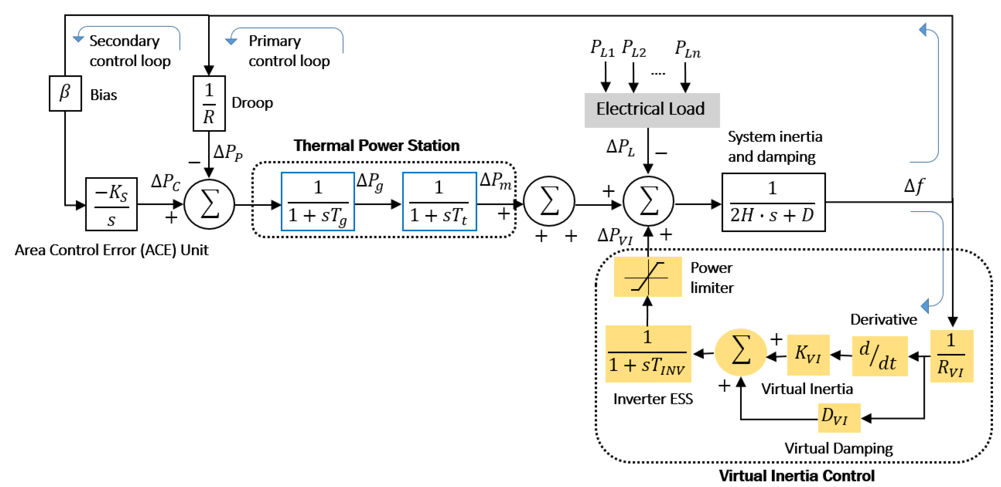
2. Fundamental Concept and Structure of Virtual Inertia Control

Primary Frequency Regulation (PFR) is the very fast acting regulation in the system (2 to 30 s). This triggers the activation of a short-term rolling reserve in situations where imbalances between power generation and demand might lead to frequency fluctuations in the electrical grid. These imbalances are mainly produced by variations in demand when the electrical system is in normal operating conditions and by sudden disconnections of electrical generation or demand. On the other hand, Secondary Frequency Regulation (SFR) refers to the method of reinstating the balance of active power between generation and demand, through the activation of the secondary reserve. In Figure 1a, you can see the periods of action of the PFR and SFR, where a drop in the nominal value (60 Hz) has been caused at 58.85.
The power reserve intended for frequency regulation is defined seasonally by the energy control centers, and its compliance is mandatory for all generators, as is the reserve for the secondary regulation for generators that meet the necessary technical characteristics for this purpose. Figure 1b shows the classification of the times required for the different types of control depending on the established time [36].
The fundamental architecture of virtual inertia control, as illustrated in Figure 2, primarily includes an energy storage system (ESS), an inverter, and a mechanism for inertial control. In this setup, inertia is artificially created by modulating the active power (W) via the inverter, which corresponds to the emulated speed of the rotor [37].
The principle of virtual inertia emulation Equation (1) implies that the nominal State of Charge (SOC) of the batteries is maintained around 50%. The emulated power by the virtual inertia control unit P V I can be simplified as:
P V I = K V I Δ f d t + D V I + P o
where,
K V I = 2 H · P I N V f o
It is important to note that Δ f d t represents the Rate of Change of Frequency (RoCoF), f o denotes the nominal frequency of the system, K V I refers to the constant or characteristics of virtual inertia, D V I indicates the constant or coefficient of virtual damping, H is the inertia constant, P I N V is the apparent power output of the inverter, and P o is the primary power transferred to the inverter. It is worth noting that, in a real synchronous machine, the resistance of the damping windings dissipates the energy of the damping term. When virtual inertial control is applied, this energy is consumed by the ESS to compensate for the system power.

3. Frequency Analysis for Virtual Inertia Control and Virtual Dropping

The dynamic representation of the suggested method is depicted in Figure 3. The main novelty of our proposal is the 1 R V I component as depicted in Equation (3), which allows us to measure the responsiveness of virtual inertia to minor frequency variations. This component is not included in the model of [38], where only the low damping regime is considered. In this sense, the equation representing the dynamics of virtual inertia model is expressed as:
Δ P V I s = s K V I + D V I 1 + s T I N V Δ f ( s ) R V I
In order to simulate our concept alongside virtual inertia control, the method utilized a schematic diagram depicting the integration of renewable energy into the electrical grid. Through this approach, the signal indicating the system frequency deviation is acquired as follows:
Δ f s = 1 2 H s + D ( Δ P m ( s ) + Δ P W ( s ) + Δ P P V ( s ) + = + Δ P V I ( s ) Δ P L ( s ) )
In which,
Δ P m ( s ) = 1 1 + s T t ( Δ P g ( s ) )
Δ P g ( s ) = 1 1 + s T g Δ P C ( s ) 1 R · Δ f ( s )
Δ P C ( s ) = K s s β · Δ f ( s )
Δ P W ( s ) = 1 1 + s T W T ( Δ P w i n d ( s ) )
Δ P P V ( s ) = 1 1 + s T P V ( Δ P s o l a r ( s ) )
where Δ P C is the secondary control’s Area Control Error (ACE) signal, Δ P P represents the signal from primary control, Δ P W T indicates the power change produced by the wind system, Δ P w i n d refers to the initial disturbance in wind generation, Δ P g is associated with the power output of the turbine system, Δ P s o l a r signifies the initial disturbance in photovoltaic generation, Δ P P V mirrors the power variation arising from the photovoltaic system, Δ P P L is the electrical load fluctuation within the system, and Δ P V I captures the change in the system’s virtual inertia.
The energy storage systems’ capacity is a key factor, defined as the maximum energy that can be discharged in a single cycle by the cell. The State of Charge (SoC) of the battery is expressed as the proportion of the remaining capacity to the battery’s total rated capacity. Equation (10) illustrates the change in SoC (dSoC), which varies based on time and the capacity C i [39].
d S O C E S S = i d t C i = S O C E S S i d t C i
The SOC of the storage systems is regulated based on the charge energy as E C and the discharge energy E D , where the reference power is established by the positive or negative reference power P E S S at two instants of time t 1 and t 2 . This characteristic is described in the following Equations (11) and (12):
E C = t 1 t 2 P E S S ( t ) d t
If the power is negative, it implies the discharge of the ESS according to the following:
E D = t 1 t 2 P E S S ( t ) d t

4. Case Study Modeling

In an interconnected electrical system, sufficient power reserve is required for reliable operation, in order to maintain the system frequency at its nominal value (60.0 Hz) or, failing that, vary around that value, maintaining the generation–load balance. Table 1 shows the power reserve percentages obtained for the Primary Frequency Regulation (PFR), in the period October 2023–March 2024: [36].
On the other hand, the restoration of the frequency to the nominal value depends on other characteristics of the system components, such as the dynamic response of the load; therefore, the Energy Markets methodology is included in the analysis, which considers these concepts. In this sense, the reserve for Secondary Frequency Regulation (SFR) must maintain the generation–load balance during demand variation under normal operating conditions [36]. Table 2 presents these results:
In the case study, a dynamic analysis of the solar-wind-diesel system is proposed with support in energy storage systems operated in island mode, considering the disturbances of renewable energies, in which the two perspectives are mainly analyzed regarding the response of the system without RES penetration and with RES penetration. The mathematical modeling and the parameters of the virtual inertia control were developed based on the characteristics of the renewable generation equipment and systems of the Centro Científico, Tecnológico y de Investigación Balzay (CCTI-B) of the University of Cuenca [26,40]; they are presented in the following Figure 4. The laboratory mainly consists of a photovoltaic generation system (35 kW), a mini wind farm (15 kW), a diesel generator (40 kVA), storage systems with Valve-Regulated Lead-Acid (VRLA) Gel battery bank (15 kWh), and a programmable electrical load that allows for the creation of step scenarios every 5 kW. The microgrid systems are connected at a Point Common Connection (PCC) on the bus in island mode as described below.
Solar Power Generation: The photovoltaic generation consists of three systems of 15 kWp, 15 kWp, and 5 kWp, as shown in Figure 4; this component has a nominal power of 35 kWp. The PV systems are connected independently to the inverters, which integrate Maximum Power Point Tracking control (MPPT). The bus configuration allows for operation in grid-connected mode or island mode.
Wind Power Generation: The laboratory is equipped with three wind turbines. Two of the wind turbines are systems with three horizontal axis blades with a nominal power of 5.5 kW each and one with a vertical axis. These correspond to the E70Pro series that integrates a permanent magnet synchronous generator. They are coupled through an AC/DC converter and subsequently a DC/AC inverter that contains an MPPT control algorithm with an efficiency greater than 97%.
Energy Storage System: A lead battery bank composed of 84 cells placed in series, A600/Solar (1130 Ah), each connected to a double flow inverter, allows for the charging and discharging of energy with the electrical grid. This system is responsible for maintaining the VIC within the established parameters. Likewise, the results are analyzed in the next section through the configuration with the drooping constant virtual controller.
Thermal Power Station: The microgrid integrates a Himoinsa diesel generator with a capacity of 40 kVA. This unit is equipped with an internal combustion engine coupled to synchronous generators. It has an Automatic Voltage Regulator (AVR) to manipulate the rotor excitation in response to load variations to ensure a constant voltage output [40].
Table 3, presented below, outlines the parameters used for virtual inertia control, tailored to the microgrid’s features as defined by Equations (1)–(9). These parameters were determined in line with the inertia emulation technology, employing the derivative method as introduced in [37]. The configuration of the parameters in the transfer function of each of the blocks was used for the simulation using the MATLAB/Simulink R2023b software.

5. Simulation Results and Discussion

The simulation explores the dynamic influence of the inertia constant H on a system’s frequency response, conducted in the absence of disturbances from renewable generation sources like Δ P w i n d and Δ P s o l a r . In this specific scenario, a gradual reduction in the inertia constant’s value is carried out, scaling down from 100% to 40%.
General considerations:
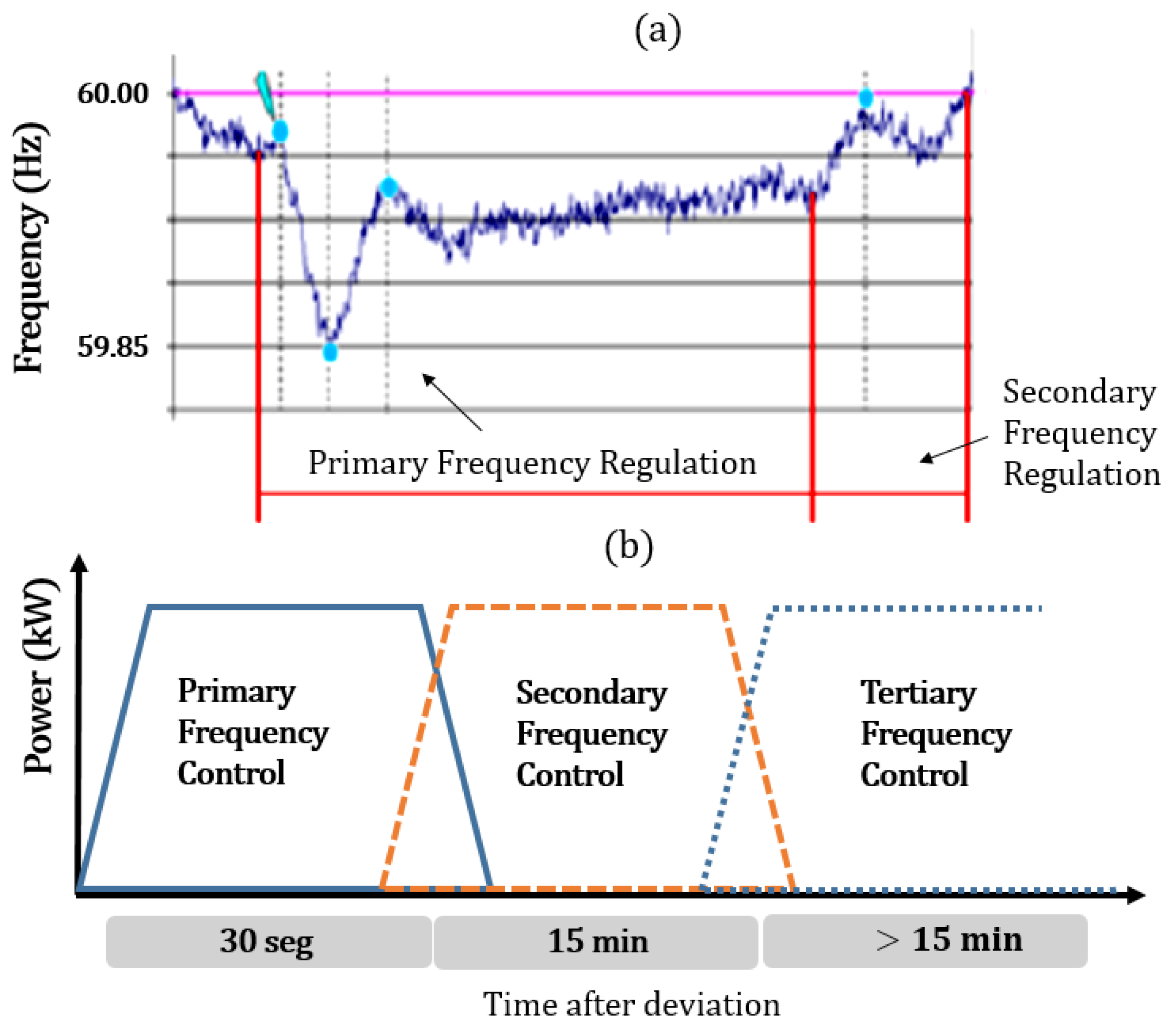
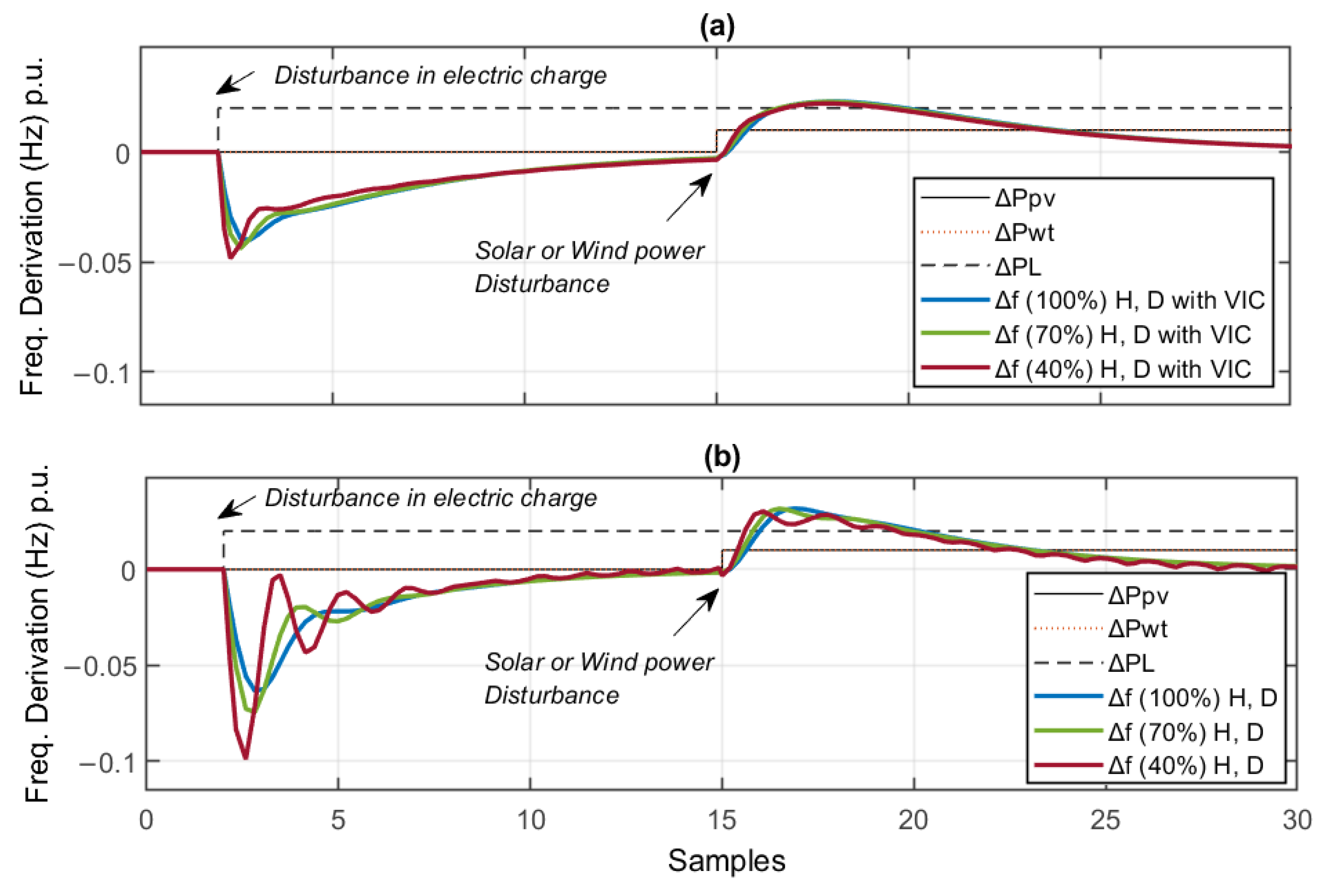
  • Under operating conditions, the contributions of wind generation, solar generation, and electrical loads are treated as uncertainties or disturbances of the system.
  • The dynamic effects of generation–load interaction are smoothed out, while primary, secondary, and virtual inertia control blocks are implemented. This is developed without compromising the results according to the literature collected in each corresponding block.
  • The virtual inertia control utilizing Energy Storage Systems (ESS) is tasked with providing power that includes the necessary inertia within a timeframe of 1 to 5 s, coinciding with the onset of disturbances caused by the integration of renewable generation into the electrical system.
  • The primary control unit’s governor is tasked with restoring the frequency system to a new stable state within the first 10 to 40 s as established by regulations.
  • The secondary frequency control’s objective is to return the system frequency to its nominal value in a set range of up to 30 min.

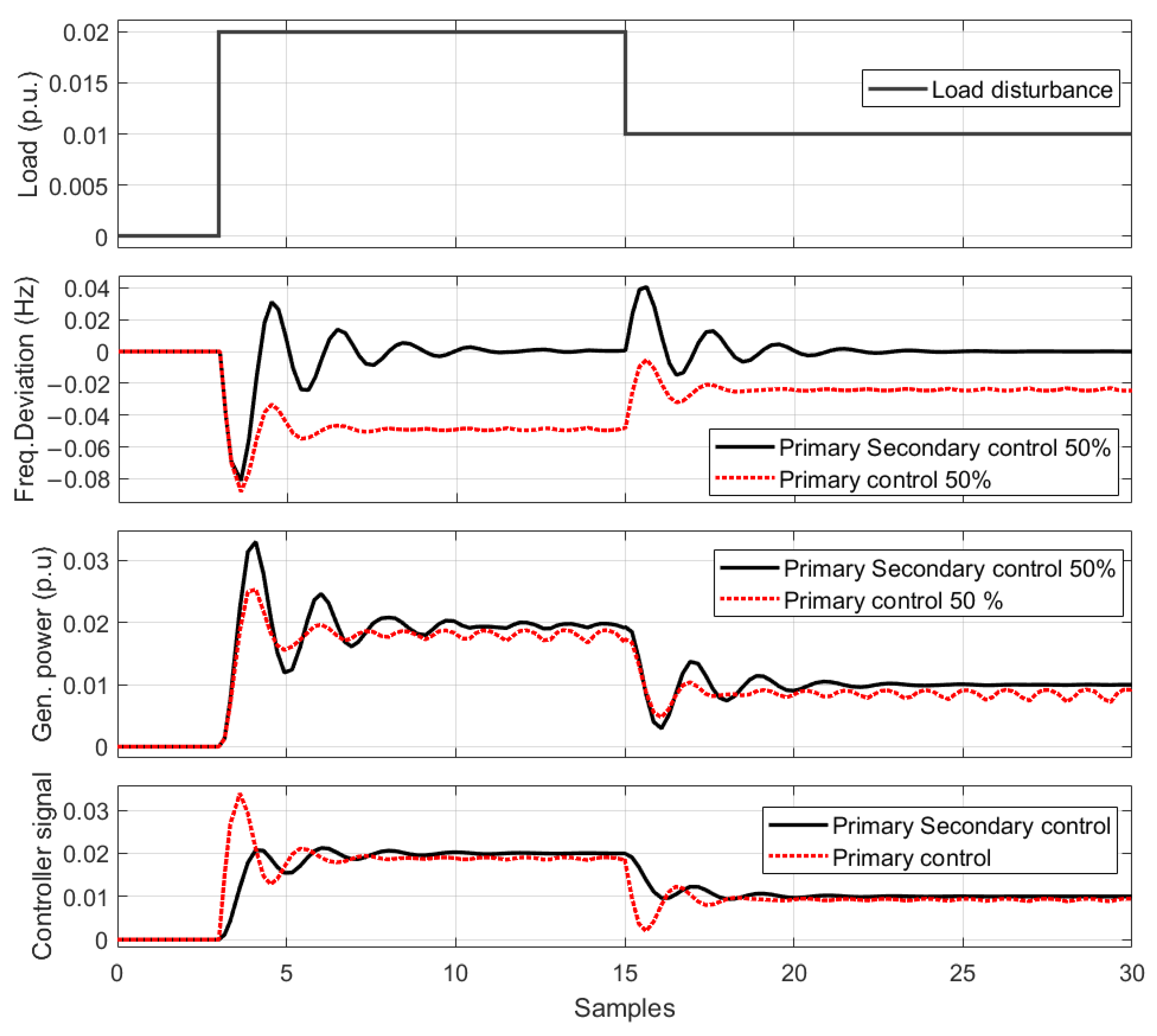
5.1. Dynamic Simulation of Frequency Response without RES Penetration

Initially, the scheme presented in the Figure 5 is analyzed without considering the penetration of RES into the electrical system.
The following Figure 6 shows the response of the system as a contribution of inertia in isolated systems without presenting disturbances in distributed generation. It can be seen that during the disturbance presented in the load, the effect of the participation of the primary and secondary controllers allows the frequency to be stabilized under normal operating conditions when the value of the inertia constant H remains at 100%.
To investigate inertia compensation in an isolated system, the inertia constant H was reduced to a value of 50%. Due to the decreased inertia, a high RoCoF value is observed, along with a larger overshoot, and ultimately, the nadir frequency increases, destabilizing the system. This is demonstrated in Figure 7.

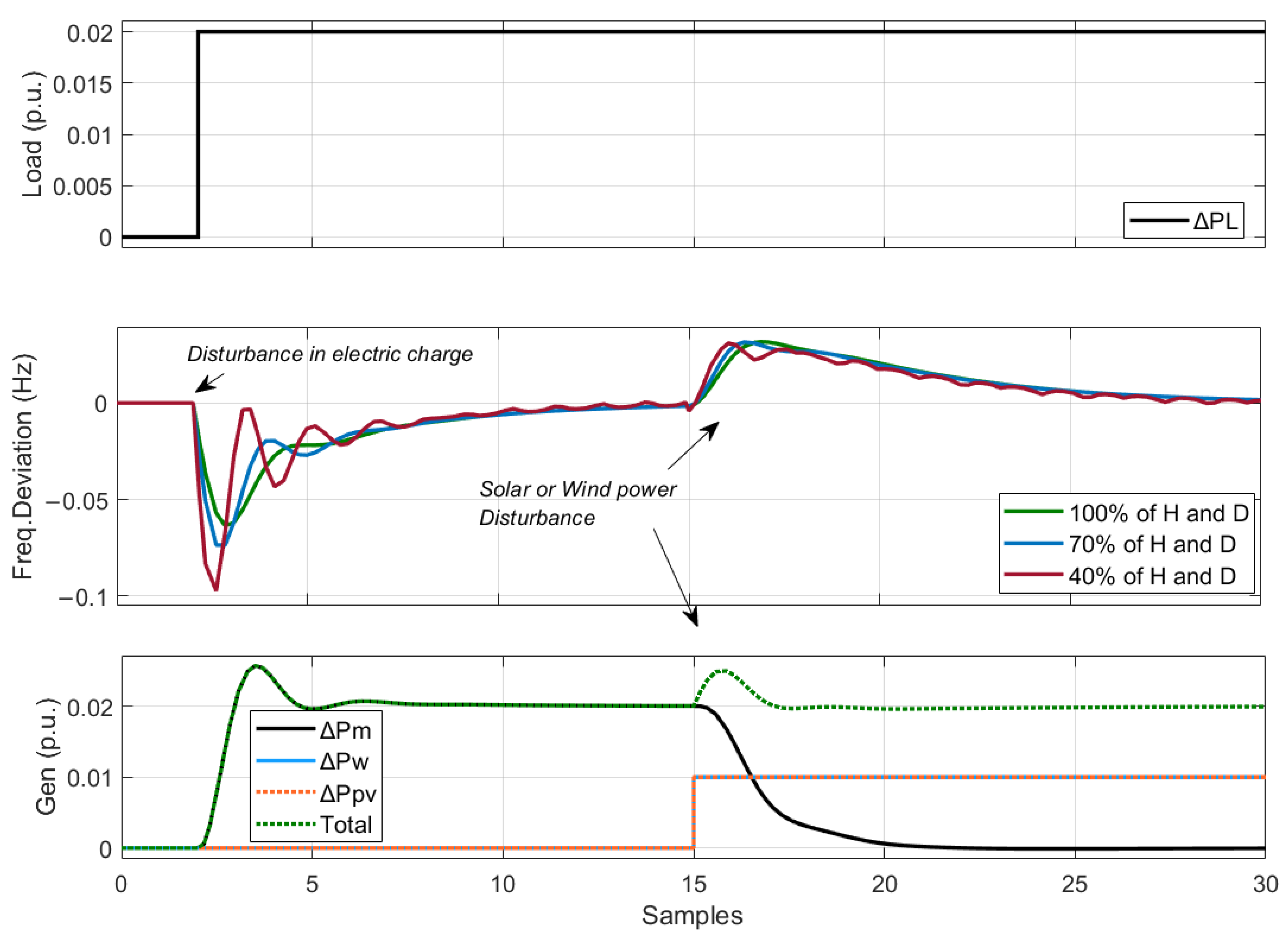
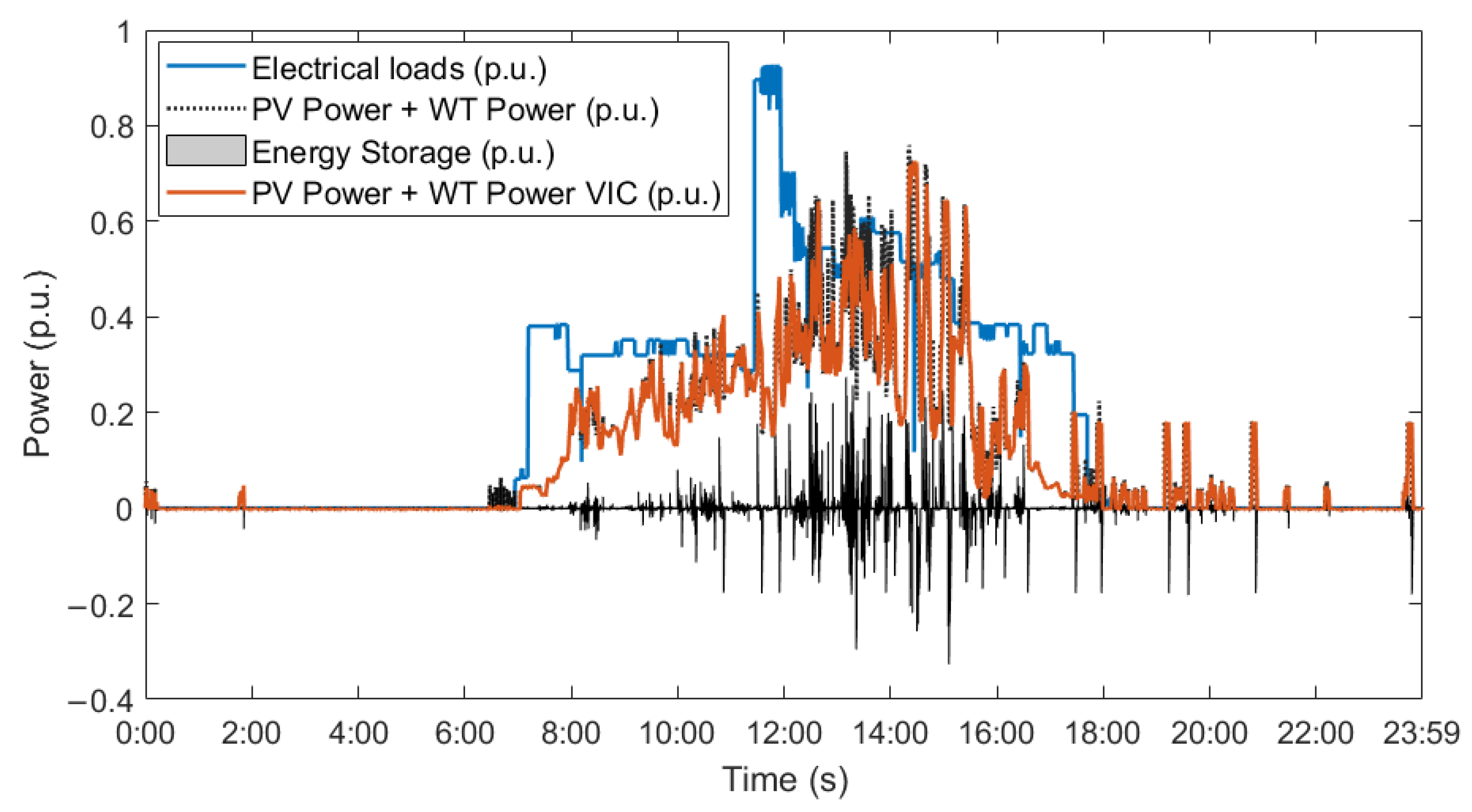
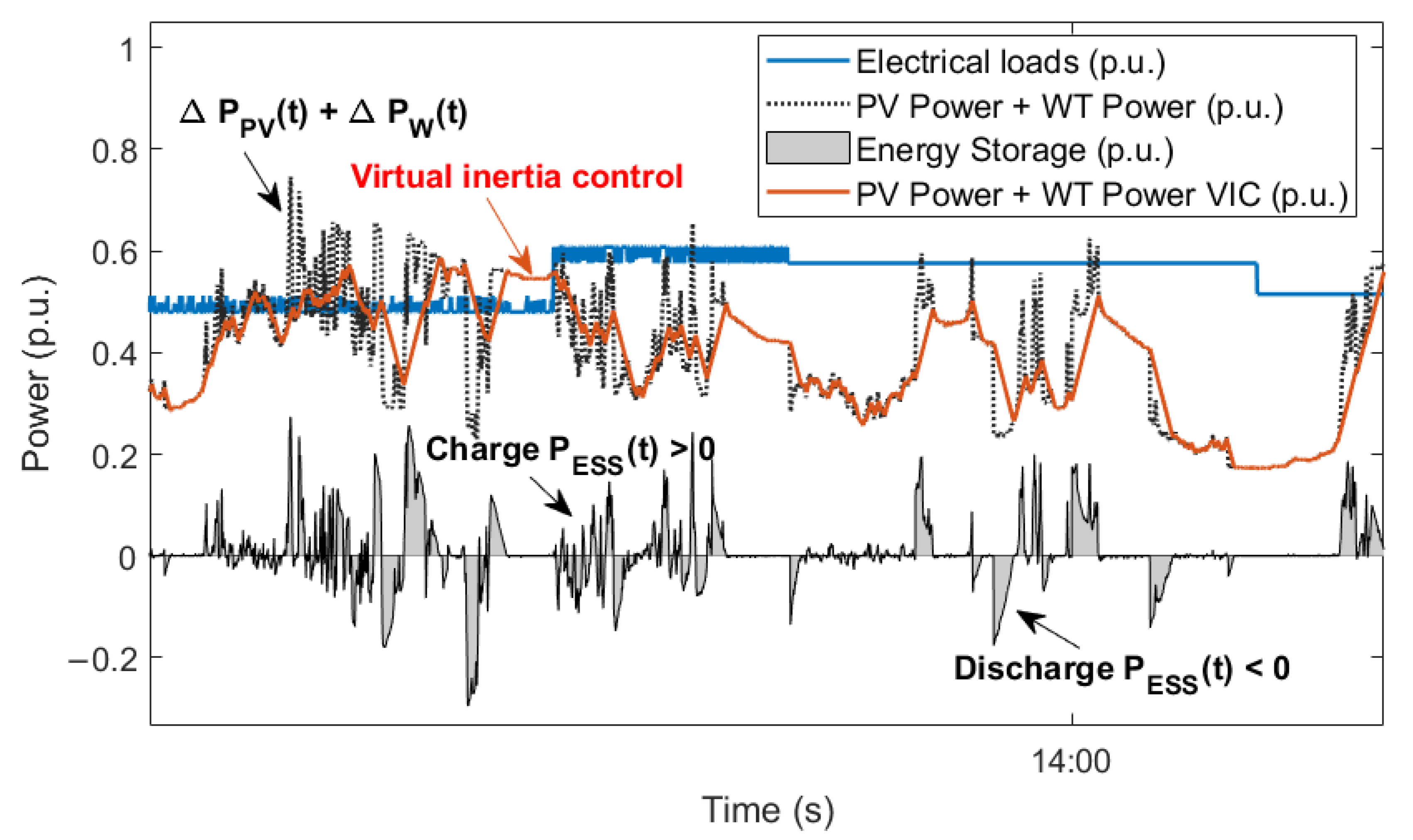
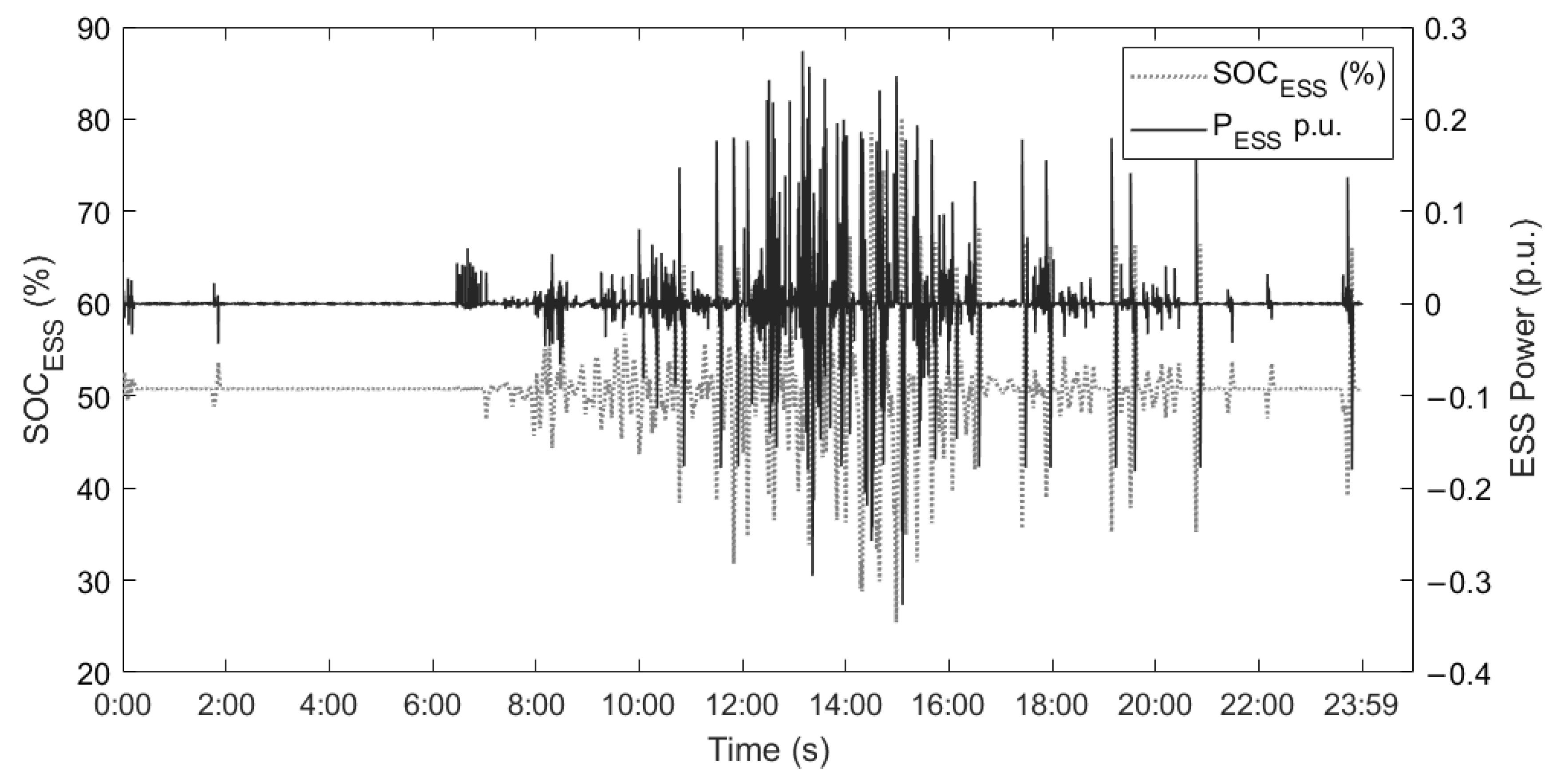
5.2. Dynamic Simulation of Frequency Response with RES Penetration

The following Figure 8 represents a scenario with penetration of wind and solar distributed generation, without considering virtual inertia emulation control. This model was developed to demonstrate a disturbance scenario of wind and solar penetration into the isolated grid.
Finally, the Simulink modeling is presented in Figure 3, showcasing the results of our novel method. By incorporating the virtual dropping block into the derivative frequency model, it is evident that the RoCoF has decreased even in the worst cases of inertia contribution to the system. An important indicator is that the Nadir frequency drops from −0.1 to −0.4 in the worst-case scenario of a constant inertia value of 40% (See Figure 9).
The following Figure 10 and Figure 11 present the response to the system by entering solar and wind power data with the use of energy storage for electrical demand with variable steps. A rapid response by the storage system can be observed when a disturbance is generated on the damage side as a generation, which significantly improves the behavior of the system in the face of possible disturbances caused in the isolated grid. The values in p.u. can reach up to 50% of their nominal power, which generates relief in the generation system.
As the Figure shows, the contribution of inertia control in response to the penetration of the RES with the storage systems where a positive and negative reference power is generated depends on the electrical grid requirement. P E S S charging and discharging values are handled by the controller. In the same way, it generates a contribution against changes in the load profile. The values in p.u. Maximum generated are between ± 0.3 .
According to Equations (10)–(12), the reference power for the P E S S storage systems and the variation of their S O C E S S can be seen in the following Figure 12 and Figure 13. In this context, the contribution of ESS in the grid is required only in the penetration of RES with high intermittency values, thus improving network stability. The reference values for the ESS are controlled by the connection/disconnection of RES and the connection/disconnection of electrical loads. This generates positive and negative values that allow one to maintain adequate SOC levels.

6. Conclusions

In this paper, a novel approach to Frequency Response Modeling for Virtual Inertia Control has been proposed. This approach aims to simultaneously emulate virtual drooping and inertia, enhancing system inertia, damping, and frequency stability during severe disturbances and contingencies.
After conducting simulations, it has been observed that the inertia constant of thermal units exhibits a higher value of H compared to the inertia constants of hydroelectric generation plants. This is evident in the initial simulations where the overshooting is lower when working with thermal transfer functions as opposed to hydraulic ones.
The high penetration of distributed generation through wind and solar generation has been shown to cause significant frequency instability in the system. Simulations indicate that as synchronous generation is displaced, the Rate of Change of Frequency and nadir frequency disproportionately increase.
In the case study presented, the value of 0.3 p.u. made it possible to significantly improve the behavior of the isolated grid when disturbances occurred in generation or demand, which made it possible to maintain stable levels in frequency regulation.
The emulation of virtual inertia control substantially reduces the RoCoF slope and maintains the nadir frequency. However, when the virtual drooping constant is added, the system stabilizes more rapidly due to its static characteristics.

Author Contributions

Conceptualization, A.C. and L.I.M.-A.; Data curation, M.T.-V. and D.S.-L.; Formal analysis, P.A.; Funding acquisition, L.I.M.-A.; Investigation, A.C. and P.A.; Methodology, D.B.; Project administration, L.I.M.-A.; Resources, M.T.-V. and D.S.-L.; Software, A.C. and D.B.; Supervision, L.I.M.-A. and F.J.; Validation, P.A. and M.T.-V., Visualization, D.B.; Writing—original draft, A.C.; Writing—review and editing, A.C., D.B. and F.J. All authors have read and agreed to the published version of the manuscript.

Funding

This research received no external funding.

Data Availability Statement

The data presented in this study are available on request from the corresponding author.

Acknowledgments

The authors thank Universidad de Cuenca for easing access to the facilities of the Microgrid Laboratory of the Centro Científico Tecnológico y de Investigación Balzay (CCTI-B), for allowing the use of its equipment, and for authorizing its staff to engage in the provision of technical support necessary to carry out the experiments described in this article. The icons used in this document were developed by Freepik, monkik, Smashicons, and Pixel perfect, from www.flaticon.com (access 30 September 2023).

Conflicts of Interest

The authors declare no conflicts of interest.

References

  1. Denholm, P.; Mai, T.; Kenyon, R.W.; Kroposki, B.; O’Malley, M. Inertia and the Power Grid: A Guide without the Spin; Technical Report; National Renewable Energy Lab. (NREL): Golden, CO, USA, 2020.
  2. Denholm, P.; Ela, E.; Kirby, B.; Milligan, M. Role of Energy Storage with Renewable Electricity Generation; National Renewable Energy Lab. (NREL): Golden, CO, USA, 2010; Volume 2. [CrossRef]
  3. Beaudin, M.; Zareipour, H.; Schellenberglabe, A.; Rosehart, W. Energy storage for mitigating the variability of renewable electricity sources: An updated review. Energy Sustain. Dev. 2010, 14, 302–314. [Google Scholar] [CrossRef]
  4. Eto, J.H.; Undrill, J.; Roberts, C.; Mackin, P.; Ellis, J. Frequency Control Requirements for Reliable Interconnection Frequency Response; Technical Report; Energy Analysis and Environmental Impacts Division Lawrence Berkeley National Laboratory: Berkeley, CA, USA, 2018.
  5. Morison, K.; Wang, L.; Kundur, P. Power system security assessment. IEEE Power Energy Mag. 2004, 2, 30–39. [Google Scholar] [CrossRef]
  6. Rakhshani, E.; Rodriguez, P. Inertia emulation in AC/DC interconnected power systems using derivative technique considering frequency measurement effects. IEEE Trans. Power Syst. 2016, 32, 3338–3351. [Google Scholar] [CrossRef]
  7. Kenyon, R.W.; Hoke, A.; Tan, J.; Hodge, B.M. Grid-following inverters and synchronous condensers: A grid-forming pair? In Proceedings of the 2020 Clemson University Power Systems Conference (PSC), Clemson, SC, USA, 10–13 March 2020; pp. 1–7. [Google Scholar]
  8. Ela, E.; Gevorgian, V.; Fleming, P.; Zhang, Y.; Singh, M.; Muljadi, E.; Scholbrook, A.; Aho, J.; Buckspan, A.; Pao, L.; et al. Active Power Controls from Wind Power: Bridging the Gaps; Technical Report; National Renewable Energy Lab. (NREL): Golden, CO, USA, 2014.
  9. Gevorgian, V.; Zhang, Y. Wind Generation Participation in Power System Frequency Response; Technical Report; National Renewable Energy Lab. (NREL): Golden, CO, USA, 2017.
  10. Brisebois, J.; Aubut, N. Wind farm inertia emulation to fulfill Hydro-Québec’s specific need. In Proceedings of the 2011 IEEE Power and Energy Society General Meeting, Detroit, MI, USA, 24–28 July 2011; pp. 1–7. [Google Scholar]
  11. Loutan, C.; Klauer, P.; Chowdhury, S.; Hall, S.; Morjaria, M.; Chadliev, V.; Milam, N.; Milan, C.; Gevorgian, V. Demonstration of Essential Reliability Services by a 300-MW Solar Photovoltaic Power Plant; Technical Report; National Renewable Energy Lab. (NREL): Golden, CO, USA, 2017.
  12. Zhou, G.; Wang, D.; Atallah, A.; McElvain, F.; Nath, R.; Jontry, J.; Bolton, C.; Lin, H.; Haselbauer, A. Synchronous condenser applications: Under significant resource portfolio changes. IEEE Power Energy Mag. 2019, 17, 35–46. [Google Scholar] [CrossRef]
  13. Wu, Z.; Gao, W.; Gao, T.; Yan, W.; Zhang, H.; Yan, S.; Wang, X. State-of-the-art review on frequency response of wind power plants in power systems. J. Mod. Power Syst. Clean Energy 2018, 6, 1–16. [Google Scholar] [CrossRef]
  14. Matevosyan, J.; Badrzadeh, B.; Prevost, T.; Quitmann, E.; Ramasubramanian, D.; Urdal, H.; Achilles, S.; MacDowell, J.; Huang, S.H.; Vital, V.; et al. Grid-forming inverters: Are they the key for high renewable penetration? IEEE Power Energy Mag. 2019, 17, 89–98. [Google Scholar] [CrossRef]
  15. Lin, Y.; Eto, J.H.; Johnson, B.B.; Flicker, J.D.; Lasseter, R.H.; Villegas Pico, H.N.; Seo, G.S.; Pierre, B.J.; Ellis, A. Research Roadmap on Grid-Forming Inverters; Technical Report; National Renewable Energy Lab. (NREL): Golden, CO, USA, 2020.
  16. Van Wesenbeeck, M.; De Haan, S.; Varela, P.; Visscher, K. Grid tied converter with virtual kinetic storage. In Proceedings of the 2009 IEEE Bucharest PowerTech, Bucharest, Romania, 28 June–2 July 2009; pp. 1–7. [Google Scholar]
  17. Karapanos, V.; de Haan, S.; Zwetsloot, K. Real time simulation of a power system with VSG hardware in the loop. In Proceedings of the IECON 2011-37th Annual Conference of the IEEE Industrial Electronics Society, Melbourne, VIC, Australia, 7–10 November 2011; pp. 3748–3754. [Google Scholar]
  18. Pogaku, N.; Prodanovic, M.; Green, T.C. Modeling, analysis and testing of autonomous operation of an inverter-based microgrid. IEEE Trans. Power Electron. 2007, 22, 613–625. [Google Scholar] [CrossRef]
  19. Liu, J.; Miura, Y.; Ise, T. Comparison of dynamic characteristics between virtual synchronous generator and droop control in inverter-based distributed generators. IEEE Trans. Power Electron. 2015, 31, 3600–3611. [Google Scholar] [CrossRef]
  20. Bonfiglio, A.; Invernizzi, M.; Labella, A.; Procopio, R. Design and implementation of a variable synthetic inertia controller for wind turbine generators. IEEE Trans. Power Syst. 2018, 34, 754–764. [Google Scholar] [CrossRef]
  21. Arani, M.F.M.; El-Saadany, E.F. Implementing virtual inertia in DFIG-based wind power generation. IEEE Trans. Power Syst. 2012, 28, 1373–1384. [Google Scholar] [CrossRef]
  22. Kerdphol, T.; Rahman, F.S.; Mitani, Y.; Hongesombut, K.; Küfeoğlu, S. Virtual inertia control-based model predictive control for microgrid frequency stabilization considering high renewable energy integration. Sustainability 2017, 9, 773. [Google Scholar] [CrossRef]
  23. Nanjun, L.; Fang, J.; Tang, Y.; Hredzak, B. A Frequency Deadband-Based Virtual Inertia Control for Grid-Connected Power Converters. In Proceedings of the 2019 10th International Conference on Power Electronics and ECCE Asia (ICPE 2019-ECCE Asia), Busan, Republic of Korea, 27–30 May 2019; pp. 1–6. [Google Scholar]
  24. Samanta, S.; Mishra, J.P.; Roy, B.K. Inertia enhancement of an isolated dc microgrid using hierarchical virtual inertia control. IETE J. Res. 2022, 68, 3149–3157. [Google Scholar] [CrossRef]
  25. Li, X.; Wang, S.; Yan, S.; Jia, X. Modeling and Robust Control with Virtual Inertia for Super-large-Scale Battery Energy Storage System. In Proceedings of the 2019 Chinese Control And Decision Conference (CCDC), Nanchang, China, 3–5 June 2019; pp. 5563–5567. [Google Scholar]
  26. Ochoa, D.; Villa, E.; Iñiguez, V.; Larco, C.; Sempértegui, R. Uso de supercondensadores para brindar soporte de frecuencia en una microrred aislada. Rev. Tecnol.-ESPOL 2022, 34, 174–185. [Google Scholar] [CrossRef]
  27. Khalid, A.; Stevenson, A.; Sarwat, A.I. Overview of technical specifications for grid-connected microgrid battery energy storage systems. IEEE Access 2021, 9, 163554–163593. [Google Scholar] [CrossRef]
  28. Cavalieri, C.; Farias, V.; Kabalan, M. Microgrid protection: A case study of a real-world industry-grade microgrid. In Proceedings of the 2021 IEEE Kansas Power and Energy Conference (KPEC), Manhattan, KS, USA, 19–20 April 2021; pp. 1–5. [Google Scholar]
  29. Shahidehpour, M.; Li, Z.; Bahramirad, S.; Li, Z.; Tian, W. Networked microgrids: Exploring the possibilities of the IIT-Bronzeville grid. IEEE Power Energy Mag. 2017, 15, 63–71. [Google Scholar] [CrossRef]
  30. Xu, H.; Yu, C.; Liu, C.; Wang, Q.; Zhang, X. An improved virtual inertia algorithm of virtual synchronous generator. J. Mod. Power Syst. Clean Energy 2019, 8, 377–386. [Google Scholar] [CrossRef]
  31. Toma, L.; Sanduleac, M.; Baltac, S.A.; Arrigo, F.; Mazza, A.; Bompard, E.; Musa, A.; Monti, A. On the virtual inertia provision by BESS in low inertia power systems. In Proceedings of the 2018 IEEE International Energy Conference (ENERGYCON), Limassol, Cyprus, 3–7 June 2018; pp. 1–6. [Google Scholar]
  32. Shi, Y.; Peng, Q.; Liu, T.; Meng, J.; Zeng, X.; Chen, G. Coordinated Virtual Inertia Control of Grid-Connected Photovoltaic-Battery Energy Storage System Considering Power Reserve and Fluctuation Smoothing. In Proceedings of the 2023 IEEE 14th International Symposium on Power Electronics for Distributed Generation Systems (PEDG), Shanghai, China, 9–12 June 2023; pp. 428–433. [Google Scholar]
  33. Sharma, K.M.; Bhimasingu, R. Energy Storage Sizing for Enhancing Microgrid Resiliency using Virtual Inertia Emulation. In Proceedings of the 2022 22nd National Power Systems Conference (NPSC), New Delhi, India, 17–19 December 2022; pp. 320–325. [Google Scholar]
  34. Liu, H.; Yang, B.; Xu, S.; Du, M.; Lu, S. Universal virtual synchronous generator based on extended virtual inertia to enhance power and frequency response. Energies 2023, 16, 2983. [Google Scholar] [CrossRef]
  35. Ochoa, D.; Martinez, S. Frequency dependent strategy for mitigating wind power fluctuations of a doubly-fed induction generator wind turbine based on virtual inertia control and blade pitch angle regulation. Renew. Energy 2018, 128, 108–124. [Google Scholar] [CrossRef]
  36. Operador Nacional de Electricidad CENACE. Available online: https://www.cenace.gob.ec/ (accessed on 20 November 2023).
  37. Kerdphol, T.; Rahman, F.S.; Watanabe, M.; Mitani, Y. Virtual Inertia Synthesis and Control; Springer: Berlin/Heidelberg, Germany, 2021. [Google Scholar]
  38. Kerdphol, T.; Rahman, F.S.; Watanabe, M.; Mitani, Y.; Turschner, D.; Beck, H.P. Enhanced virtual inertia control based on derivative technique to emulate simultaneous inertia and damping properties for microgrid frequency regulation. IEEE Access 2019, 7, 14422–14433. [Google Scholar] [CrossRef]
  39. Ohmae, T.; Sawai, K.; Shiomi, M.; Osumi, S. Advanced technologies in VRLA batteries for automotive applications. J. Power Sources 2006, 154, 523–529. [Google Scholar] [CrossRef]
  40. Espinoza, J.; Gonzalez, L.; Sempertegui, R. Micro grid laboratory as a tool for research on non-conventional energy sources in Ecuador. In Proceedings of the 2017 IEEE International Autumn Meeting on Power, Electronics and Computing (ROPEC), Ixtapa, Mexico, 8–10 November 2017; pp. 1–7. [Google Scholar]
Figure 1. (a) Periods of action of the PRF and SFR. (b) Classification of frequency reserves.
Batteries 10 00018 g001
Figure 2. Virtual inertia control structure in a microgrid.
Batteries 10 00018 g002
Figure 3. Dynamic frequency response structure for virtual inertia control.
Batteries 10 00018 g003
Figure 4. Micro-grid laboratory—case study (CCTI-B).
Batteries 10 00018 g004
Figure 5. Dynamic simulation of frequency response without RES penetration.
Batteries 10 00018 g005
Figure 6. Dynamic response when primary and secondary control actuates in an isolated system.
Batteries 10 00018 g006
Figure 7. Dynamic response when the inertia constant H drops to 50% without virtual inertia control.
Batteries 10 00018 g007
Figure 8. Frequency response simulink model when there is wind and solar penetration in system.
Batteries 10 00018 g008
Figure 9. Frequency response wind and solar penetration (a) virtual inertia control and (b) virtual dropping.
Batteries 10 00018 g009
Figure 10. System response with wind and solar penetration through variation of electrical demand in steps.
Batteries 10 00018 g010
Figure 11. System response with wind and solar penetration through variation of electrical demand in steps (section).
Batteries 10 00018 g011
Figure 12. S O C E S S response with wind and solar penetration.
Batteries 10 00018 g012
Figure 13. S O C E S S response with wind and solar penetration (section).
Batteries 10 00018 g013
Table 1. Power reserve percentages for PFR.
Condition% Reserve under the Effective Power of the Generators
Interconnected Ecuador2.0
Isolated Ecuador3.0
Table 2. Reserve required for secondary frequency regulation.
DEMANDAbove Reserve Required for SFR (MW)Below Reserve Required for SFR (MW)
Minimum187.50105
Half187.50105
Maximum187.50105
Table 3. System and control parameter values.
DescriptionSymbolParameter Value
Thermal Power Station (Governor) T g 0.07
Thermal Power Station (Turbine) T t 0.37
Wind Generation Unit T W T 1.4
Solar Generation Unit T P V 1.9
Primary control loop—droop 1 / R 1/2.6
Secondary control loop—bias β 0.98
Area control error K S 0.1
Proporcional compoment VIC R V I 2.7
Virtual damping coefficient D V I 0.016
Inertia constantH0.083
Virtual inertia characteristics K V I −0.6
Disclaimer/Publisher’s Note: The statements, opinions and data contained in all publications are solely those of the individual author(s) and contributor(s) and not of MDPI and/or the editor(s). MDPI and/or the editor(s) disclaim responsibility for any injury to people or property resulting from any ideas, methods, instructions or products referred to in the content.

