Article

Two-Step Synthesis of ZnS-NiS2 Composite with Rough Nanosphere Morphology for High-Performance Asymmetric Supercapacitors

Key Laboratory for Ultrafine Materials of Ministry of Education, Shanghai Key Laboratory of Advanced Polymeric Materials, School of Materials Science and Engineering, East China University of Science and Technology, Shanghai 200237, China
*
Author to whom correspondence should be addressed.
Batteries 2024, 10(1), 16; https://doi.org/10.3390/batteries10010016
Submission received: 1 December 2023 / Revised: 26 December 2023 / Accepted: 29 December 2023 / Published: 31 December 2023
(This article belongs to the Special Issue High-Performance Super-capacitors: Preparation and Application)

Abstract

:
Transition metal sulfides have excellent electrochemical performance and show great potential for improving the energy density of asymmetric supercapacitors. This study demonstrates a two-step synthesis technique and highlights the enhanced energy storage efficiency of ZnS-NiS2 composite materials for asymmetric supercapacitors. The composite materials of ZnS nanosheets and NiS2 nanocrystals are characterized by a rough surface and spherical shape. The sample with the optimal ratio (ZnS-NiS2-1:7) exhibits a maximum specific capacitance of 1467.9 F g−1 (550.5 C g−1) at 1 A g−1. The specific capacitance of the ZnS-NiS2-1:7 sample is 26.1% higher compared to the pure NiS2 sample. Furthermore, the assembled ZnS-NiS2-1:7//AC device shows a high specific capacitance of 127.8 F g−1 (217.3 C g−1) at 1 A g−1 and an energy density of 51.3 Wh kg−1 at a power density of 820.8 W kg−1. The ZnS-NiS2-1:7 sample has exceptional energy storage capability on its own, but it can also be composited with graphene to further increase the specific capacitance (1681.0 F g−1 at 1 A g−1), suggesting promising prospects for the ZnS-NiS2-based composite material in the future.

1. Introduction

Environmental issues resulting from fossil fuel consumption have prompted researchers to concentrate on energy conversion and storage devices as practical alternatives to the ever-increasing demand for fossil fuels. Therefore, the evolution of energy storage devices, like batteries, fuel cells, and supercapacitors (SCs), has been the subject of numerous studies [1,2]. SCs are among the most promising electrochemical energy storage devices, with advantages such as high energy density, quick charge/discharge, and high cycling stability [3]. However, SCs have a disadvantage in terms of their relatively low energy density in comparison to batteries. As a result, searching for stable electrode materials designed for providing high energy density is never ending [4]. According to the energy storage mechanism, SCs can be divided into “pseudo-capacitors” and electric double-layer capacitors (EDLC) [5]. In order to address the limitations associated with comparatively low energy density, asymmetric supercapacitor (ASC) devices were assembled with a pseudo-capacitor electrode and an EDLC electrode to show high energy density [6]. The energy density of ASC devices can be improved by effectively employing the potential gap between two kinds of electrodes and expanding the entire voltage window.
Transition metal compounds such as transition metal oxide [7,8], transition metal hydroxide [9,10], and transition metal sulfide (TMS) are considered appropriate pseudo-capacitor materials. Among them, TMS has the advantages of high energy density, high conductivity, and good cycle stability. According to the literature, as the electronegativity of sulfur is lower than that of oxygen, the TMS has more flexibility in structure design and higher ion diffusivity [11,12,13]. In the field of TMS, nickel sulfide is very attractive because of its high theoretical capacity, good cyclic stability, simple synthesis, and low cost. Xie [14] et al. synthesized a composite material of α-NiS, β-NiS, Ni3S4, and rGO by reducing thiourea. The composite material exhibited a high specific capacity of 609.4 C g−1 at 1 A g−1 and a high coulombic efficiency of 99.5%. Wang [15] et al. developed MoS2/NiS composite electrode materials with electrochemical deposition, ionic layer adsorption, and reaction methods. The MoS2/NiS composite showed a specific capacitance of 721.4 mF cm−2 at a current density of 1 mA cm−2. Dar [16] et al. synthesized manganese-doped tin sulfide (SnS) NPS with varying manganese doping ratios (XMn = 0–9%) using the solvothermal method. The resulting single-phase orthorhombic crystal structure exhibited an increase in specific capacitance values from 9 to 30 (F g−1) with Mn dopant, suggesting that external impurities have enhanced the potential of pure SnS NPs as an alternative source for energy storage devices. Zhang [17] et al. synthesized nanoparticles of NiS and NiS2 through a solid-phase synthesis method. The morphology of NiS and NiS2 is controlled by the molar ratio of Ni and S. The obtained nanoparticles showed a specific capacitance of 1072.6 F g−1 at 2 A g−1. Furthermore, synthesizing binary metal sulfides and controlling the morphology of electrode materials has been proven to be an effective way to promote the electrochemical properties of the electrode materials [18].
ZnS is a proficient metal conductor that facilitates the transport of ions and electrons. It has been widely used in different applications, such as inorganic–organic hybrid photovoltaics [19], solar cells [20], and photocatalysts [13]. Furthermore, ZnS also has a high theoretical capacitance, a wide bandgap of 3.5 to 3.8 eV, and rich redox activity, making it attractive for electrode applications [21]. Palanisamy [22] et al. reported composite electrode materials of WO3-ZnS prepared through a microwave assisted method. The morphology of the WO3-ZnS composites was irregular nanoparticles, which can be controlled through selective absorption of the microwave. The WO3-ZnS composites showed a specific capacitance of 215.0 F g−1, which is 171.0 F g−1 higher than that of WO3. This notable enhancement in specific capacitance can be attributed to the high charge transfer rate of ZnS. Yu [23] et al. prepared Cu5Sn2S7-ZnS composite materials using a solvothermal method. The surface of the Cu5Sn2S7-ZnS composite showed a flower-like structure. According to electrochemical tests, the addition of ZnS may significantly improve the specific capacitance of Cu5Sn2S7, which can be attributed to the synergistic effect between Cu5Sn2S7 and ZnS. The assembled supercapacitor device showed an energy density of 11.1 Wh kg−1 at a power density of 461.0 W kg−1. In order to construct a supercapacitor with excellent energy density, composite electrode materials must be designed properly.
According to our review of the relevant literature, no research has been conducted on the facile synthesis and characterization of ZnS-NiS2 composite electrode materials. Our research suggests that composite electrode materials made of ZnS and NiS2 will have improved performance due to the synergistic effect of the high specific capacitance provided by NiS2 and the higher ion and charge transfer rates delivered through ZnS. The unique combination of flake ZnS and spherical NiS2 provides a new idea for high performance composite materials. Additionally, ZnS-NiS2 composite materials have the advantages of simple composition, cost-effectiveness, and environmental friendliness. This paper suggests an interesting research direction for synthesizing optimized composite materials for supercapacitors.
Herein, we have synthesized the composite electrode materials of ZnS and NiS2 by using the colloidal chemical method and the solvothermal method, respectively. The obtained ZnS-NiS2 composites have the morphology of nanospheres with rough surfaces. The electrochemical performances of the NiS2-based composites were improved by introducing a low portion of ZnS. The optimized ZnS-NiS2-1:7 sample showed a high specific capacitance of 1467.9 F g−1 at 1 A g−1 and outstanding energy storage properties. After assembly with commercial activated carbon (AC), the ZnS-NiS2-1:7//AC device showed a high energy density of 51.3 Wh kg−1 at a power density of 820.8 W kg−1 and good cyclic stability of 94.9% retention after 5000 cycles. Furthermore, ZnS-NiS2-1:7 can be composited with graphene nanosheets to achieve an even higher specific capacitance of 1681.0 F g−1 at 1 A g−1.

2. Materials and Methods

2.1. Synthesis of ZnS Nanosheets

ZnS nanosheets were prepared through a colloidal chemical method. First, 0.5 mmol of zinc acetylacetonate (Zn(C5H7O2)2) was dissolved in 20 mL of oleylamine (OLA). The mixed liquid was magnetically stirred for 30 min to obtain a uniform solution. The solution was transferred into a four-necked flask and heated to 120 °C under a N2 atmosphere for 30 min. Subsequently, 3.6 mmol of sulfur powder, dissolved in 5 mL of OLA, was gradually added to the four-necked flask. After that, the temperature was quickly increased to 330 °C and maintained for 6 h. After cooling down to room temperature naturally, the solution was washed several times with a mixture of cyclohexane and ethanol and dried at 60 °C for 12 h. Eventually, ZnS samples were annealed under the N2 atmosphere at 500 °C for 2 h before sealed storage.

2.2. Synthesis of ZnS-NiS2 Composites

ZnS-NiS2 composites were synthesized by a solvothermal method. A certain amount of ZnS nanosheets prepared in the previous step was added to 50 mL of N,N-dimethylformamide (DMF) and ultrasonicated for an hour. After that, 1.5 mmol of nickel acetate (Ni(CH3COO)2·4H2O) and 9.3 mmol of thioacetamide (CH3CSNH2) were added to 25 mL of ethanol and magnetically stirred for 0.5 h. The above two solutions were mixed and transferred into a 100 mL Teflon-lined stainless-steel autoclave. The autoclave was sealed and heated to 150 °C for 1.5 h. After cooling down to room temperature, the ZnS-NiS2 samples were collected by centrifugation and washed several times with deionized water and ethanol. Finally, the ZnS-NiS2 composites were dried at 60 °C for 12 h. Different composite ratios of ZnS and NiS2 (0:1, 1:9, 1:7, 1:5) were achieved by controlling the amount of ZnS nanosheets and were named ZnS-NiS2-0:1, 1:9, 1:7, and 1:5, respectively.

2.3. Synthesis of ZnS-NiS2-G Composites

ZnS-NiS2-G composites were synthesized by a facile physical method. An amount of 100 mg of the prepared ZnS-NiS2-1:7 sample was added to 20 mL of ethanol. A certain amount of graphene powder was weighed and added to the above-mentioned mixed liquid. The mixed liquid was further processed by ultrasonic treatment for 30 min to form a uniform dispersion. The dispersion was magnetically stirred for 24 h, and the container was sealed to avoid ethanol volatilization. Finally, the black powders were collected through centrifugation. ZnS-NiS2-G composites were washed several times with deionized water and ethanol and dried at 60 °C for 12 h. The ZnS-NiS2-G composites with different graphene mass ratios were synthesized by controlling the weight of graphene powder and were named ZnS-NiS2-G (3%, 5%, 7%, 9%).

2.4. Materials Characterization

The crystal structures of the samples were characterized by X-ray diffraction (XRD) in a D/max2550VB/PC diffractometer with Cu Kα radiation (λ = 1.5418 Å), and 2θ ranged from 10° to 80°. The X-ray photoelectron spectrometer (XPS, Thermo Fisher ESCALAB 250Xi, Waltham, MA, USA) was used to examine the elemental composition and their chemical states on the shallow layer of the sample surface. The surface morphology of samples was studied by field emission scanning electron microscopy (S-4800, Hitachi, Tokyo, Japan). Transmission electron microscopy (TEM) was performed on a JEL-2100 electron microscope to take higher-resolution images. Selected area electron diffraction (SAED) was performed to analyze the crystal properties of samples.

2.5. Electrochemical Measurements

The electrochemical properties of the samples were characterized by a three-electrode system. A 3 M KOH solution was used as the electrolyte. The nickel foam coated with synthesized electrode material (1 cm × 3 cm) was used as the working electrode. A piece of platinum foil (1 cm × 1 cm) was utilized as the counter electrode, and a saturated calomel electrode (SCE) was used as the reference electrode.
Cyclic voltammetry (CV) and galvanostatic charge/discharge (GCD) tests were performed on an electrochemical workstation (Bio-Logic, Seyssinet-Pariset, France). The electrochemical impedance spectra (EIS) test was operated on a CHI 660E electrochemical workstation. The amplitude of the sinusoidal voltage was set at 5 mV, with a frequency range of 0.01 Hz to 100 kHz.
The working electrode was prepared using the following method: The obtained samples, carbon black, and polyvinylidene fluoride (PVDF), were mixed with a mass ratio of 80:10:10. A few drops of N-methylpyrrolidone (NMP) solutions were added to the mixture. The mixture was stirred by hand for 25 min and brushed onto a piece of nickel foam. The prepared nickel foam was dried at 60 °C for 12 h. The loading mass of electrode materials on each nickel foam was about 2–3 mg.
A supercapacitor device was assembled with prepared samples and commercial AC. A 3 M KOH solution was used as the electrolyte, and a circular polytetrafluoroethylene (PTFE) film was utilized as the separator to separate the two electrodes. The assembled HSC device was passed through the manual tablet press, and the thickness of the active material electrodes was negligible at the micron scale. The values’ specific capacitance (C), energy density (E), and power density (P) can be calculated with the following equations [24,25]:
C = It/mV
E = 1/2 CV2
P = E/t
where C (F g−1) is the mass specific capacitance of the active material, I (A g−1) is the discharging current, t (s) is the discharging time, m (g) is the mass of the active materials, and V (V) is the working potential in the charging–discharging process. The loading mass of the positive electrode and the negative electrode in supercapacitor devices can be calculated by the following equation [24]:
m+/m = C V/C+V+
where m+ and m (g) are loading masses of active materials, C+ and C (F g−1) are the specific capacitances, and V+, V (V) are the working potential windows of the positive and negative electrodes.

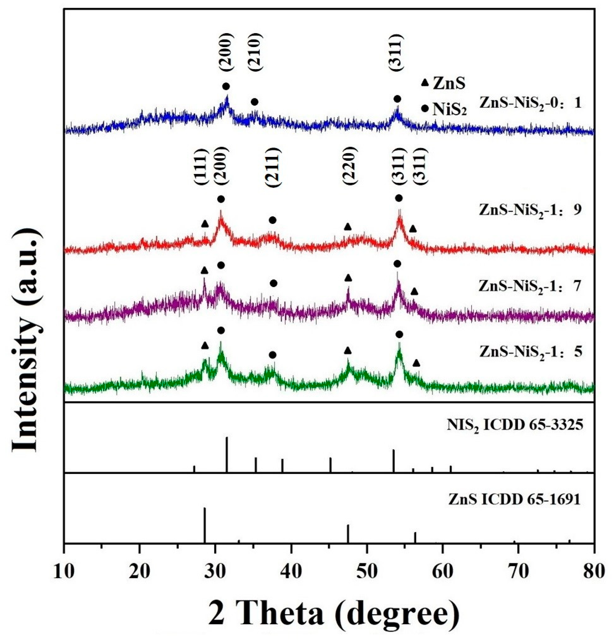
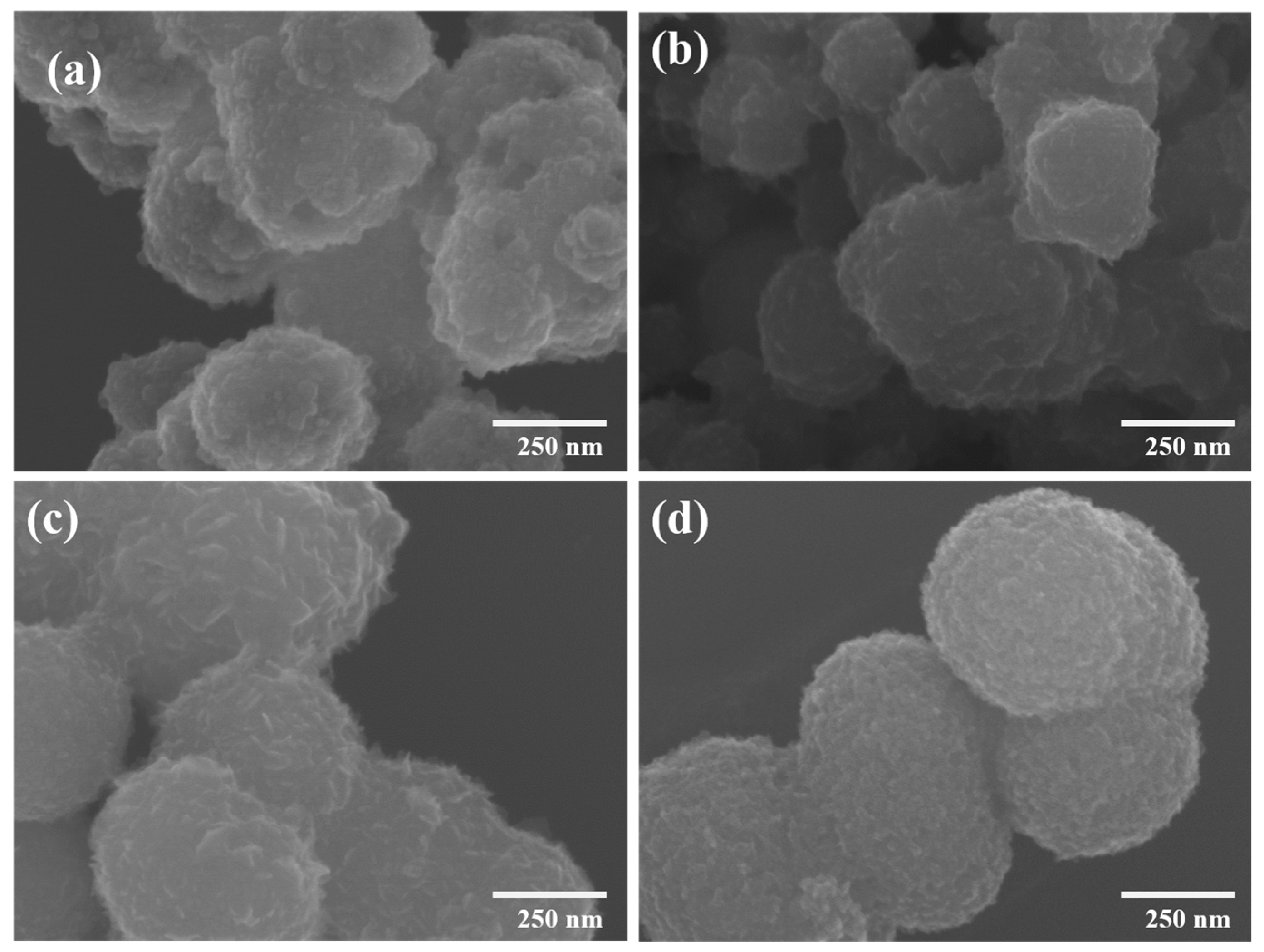
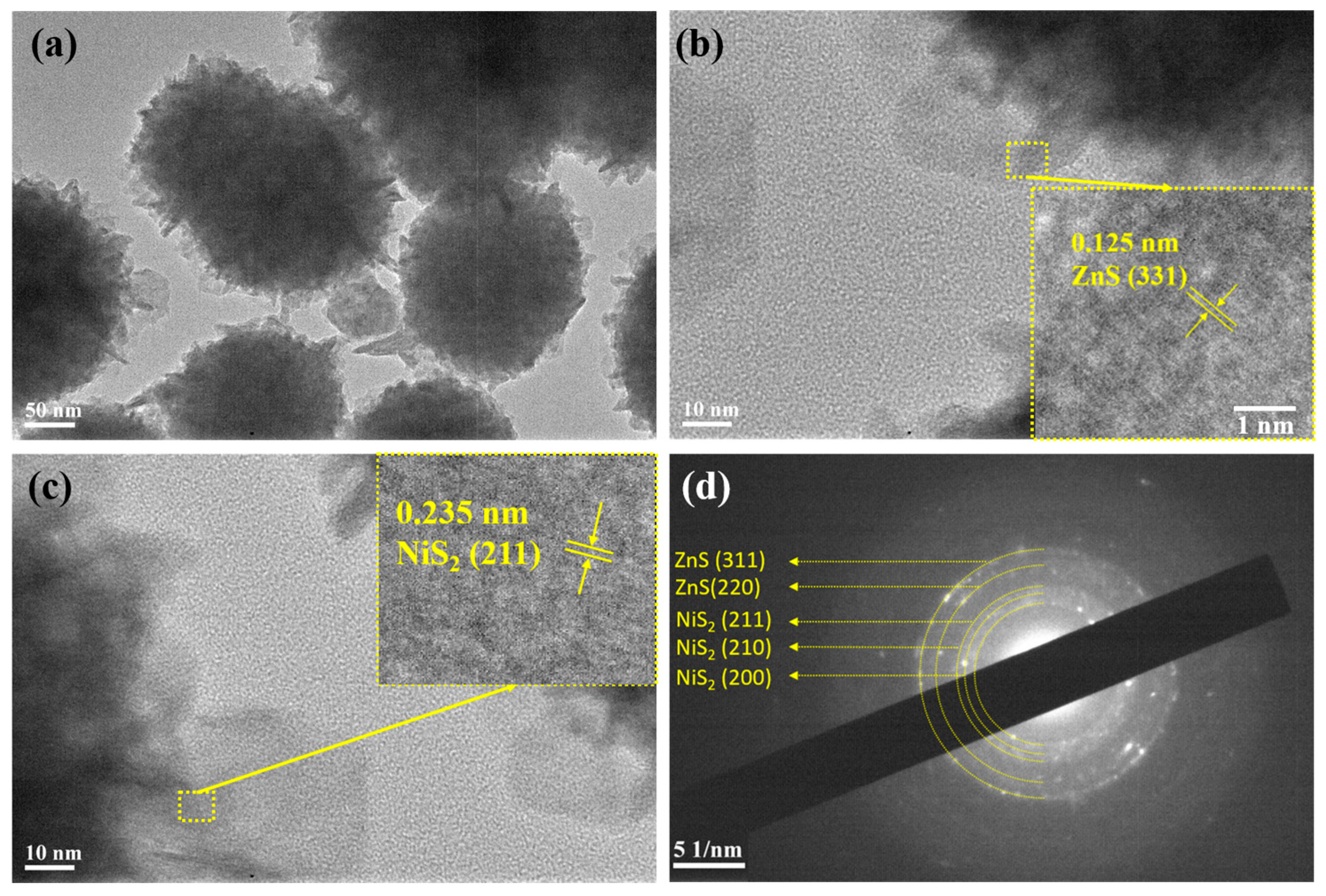
3. Results and Discussion

The synthesis process of the ZnS-NiS2 composite sample is shown in Figure 1. First, zinc acetylacetonate powder and sulfur powder were dispersed in oleylamine, respectively. After that, the two dispersions were heated in a four-necked flask at 330 °C under the N2 atmosphere. The products were annealed at 500 °C to remove organic impurities and the ZnS nanosheets were collected for further use. The composites of ZnS-NiS2 were synthesized by a solvothermal method, which was achieved at a relatively low temperature and in a short time.
The crystal structure of the ZnS-NiS2 samples was studied by XRD analysis. Figure 2 shows the XRD patterns of ZnS-NiS2 samples with different composite ratios. For the pure NiS2 sample (ZnS-NiS2-0:1), the peaks at 31.5°, 35.4°, and 53.5° can be matched with the (200), (210), and (311) crystal planes of NiS2 (ICDD 65-3325), respectively. For the ZnS-NiS2 composite samples, diffraction peaks of both ZnS and NiS2 crystals can be found. The diffraction peaks at about 31.0°, 37.8°, and 53.5° can be matched with the (200), (211), and (311) crystal planes of NiS2 (ICDD 65-3325). According to our search results, ICDD 65-3325 is the most matched stand card, where the diffraction peak of the (211) crystal plane in the standard card is located at 38.8°, but the peak in the XRD pattern was 1.0° lower than the standard card value. According to the Bragg equation, the expansion of crystal plane spacing was calculated to be 0.04 Å. Such a peak shift happens when ZnS and NiS2 are composited together, which could be related to the stress at the ZnS/NiS2 interfaces and/or Zn doping into the NiS2 nanocrystal lattices. The size of the crystalline domains in a material can also influence the XRD pattern. In ZnS-NiS2 composites, the presence of NiS2 nanoparticles dispersed within the ZnS matrix can lead to size effects. The size of the nanoparticles can affect the peak positions due to changes in the crystallite size, strain, and lattice parameters [26].
The peaks at 28.6°, 47.5°, and 56.4° can be matched with the (111), (220), and (311) crystal planes of the ZnS (ICDD 65-1691), confirming the formation of the ZnS-NiS2 composite. Furthermore, the peaks of NiS2 in the composites are relatively wide and weak, indicating that the low crystallinity of NiS2 is due to the short heating time and low heating temperature during the solvothermal process. The Debye-Scherrer equation was used to calculate the average size of NiS2 crystals in the directions perpendicular to the (200) and (311) crystal planes as 7.7 and 9.5 nm. As the concentrations of ZnS in the composites are low, the ZnS signals are generally weaker than those of NiS2. However, in the ZnS-NiS2-1:7 sample, the ZnS signals are narrower and have higher intensities, suggesting that the ZnS nanosheets are larger in size than in the other composites, which will be discussed further below.
Figure 3 displays the FESEM images of the ZnS-NiS2 samples. The morphology of the composite samples is quite similar; they all appear to be rough spheres. As illustrated in Figure 3a, when the ZnS composite ratio is 0, roundish protrusions can be observed on the surface of NiS2 nanospheres. However, the average particle size is about 265 nm, and they gather into a cluster. The ZnS-NiS2 composites in Figure 3b–d exhibit sharper protrusions on the surfaces of the spheres, indicating the presence of ZnS nanosheets. Among these, the nanosheet morphology on the surface is most clearly observed in Figure 3c. This observation is consistent with the XRD analysis, showing significant growth in the size of the nanosheets in the ZnS-NiS2-1:7 sample. In Figure 3b, the particle size is reduced to some extent compared with Figure 3a. On the other hand, the ZnS-NiS2-1:7 and ZnS-NiS2-1:5 samples show similarity to Figure 3a. As shown in Figure 3c, the ZnS-NiS2-1:7 sample exhibits a greater amplitude of surface fluctuation. This characteristic facilitates the enhancement of a larger specific surface area, hence exposing a greater number of active sites for redox reactions. When the ZnS concentration is further increased, as shown in Figure 3d, there are more surface height fluctuations at a certain length. These fluctuations may be attributed to the higher ZnS concentration. However, the surface fluctuation amplitude is not as high as that of the ZnS-NiS2-1:7 sample. This observation suggests that the ZnS nanosheets are now relatively closely attached to the sphere surfaces. As a result, the growth of ZnS into larger nanosheets during the synthesis process is slowed down.
Furthermore, the morphology of the ZnS-NiS2-G (5%) sample was also studied. As illustrated in Figure S1 in the Supplementary Materials, the sample exhibited both graphene nanosheets and ZnS-NiS2-1:7 nanoparticles.
EDS mapping tests were performed on the ZnS-NiS2-1:7 sample to identify the distribution of S, Ni, and Zn elements in the sample, as shown in Figure 4. The FESEM image of the ZnS-NiS2-1:7 sample is shown in Figure 4a, while Figure 4b–d show the distribution of S, Ni, and Zn elements, respectively. It can be seen that the distribution areas of Ni and S elements are consistent with the areas of the ZnS-NiS2-1:7 nanospherical composite. The signals of the Zn elements are characterized by a comparatively low level and scattered distribution. However, there is a slightly higher density of signal spots observed in the composite sample area, which aligns with the sample region depicted in Figure 4a. The low Zn signal level is caused by the low concentration of Zn in the composite sample.
The detailed morphology and internal structure of the ZnS-NiS2-1:7 sample were further studied through TEM, as shown in Figure 5. Figure 5a shows the TEM image of the ZnS-NiS2-1:7 sample, which clearly shows that the sample is composed of nanospheres with nanosheets visible on the sphere surfaces. This observation should not simply be interpreted as evidence of core-shell structures with a NiS2 core and ZnS nanosheet shell for the rough spheres. In the synthesis procedures, the nanosheets are initially prepared, followed by the synthesis of NiS2 nanocrystals from the surrounding solutions. Subsequently, the limited signal penetration depth of the TEM technology hinders the clarity of the inner regions of the spheres. However, the existence of nanosheets within the spheres cannot be dismissed. Conversely, the TEM image provides substantial evidence of nanosheets within the central region of numerous spherical particles. Figure 5b,c show HRTEM images of the sample. Upon closer zooming of the region enclosed by the yellow dashed box in Figure 5b, a set of lattice stripes with a spacing of 0.125 nm is found. This observation suggests a correlation between these lattice stripes and the (331) crystal plane of ZnS. Similarly, upon zooming in on the region enclosed by the dashed box in Figure 5c, a set of lattice stripes with a spacing of 0.235 nm is observed, which corresponds to the (211) crystal plane of NiS2. The HRTEM images not only demonstrate the presence of both ZnS and NiS2, but also eliminate the proposed core-shell structure by observing both ZnS and NiS2 on the sphere surfaces. Figure 5d shows the SAED image of the ZnS-NiS2-1:7 sample, which shows diffraction spots distributed on several concentric diffraction rings. These rings can be matched with the (311) and (220) crystal planes of ZnS and (211), (210), and (200) crystal planes of NiS2, respectively. The SAED image confirms the existence of ZnS and NiS2 crystalline phases in the composite material. XPS was used to examine the surface composition and chemical states of the ZnS-NiS2-1:7 sample, as shown in Figure S3. Furthermore, TEM and SAED images of the ZnS-NiS2-G (5%) sample can be seen in Figure S2.
The electrochemical performance of the ZnS-NiS2 samples was tested in a three-electrode system. A 3 M KOH solution was used as the electrolyte. However, a CV test was performed to study the redox behavior of the ZnS-NiS2 samples during the charge and discharge processes. Figure 6a shows the CV curves of the ZnS-NiS2-1:7 sample at different scan rates. The range of the potential window was set to be −0.25–0.65 V. Notably, redox peaks can be observed clearly in Figure 6a. This observation confirms that faradaic reactions occurred during the charge and discharge processes, and the ZnS-NiS2-1:7 sample exhibits pseudo-capacitive behavior. When the scan rate increases, the positions of the redox peaks shift to higher and lower potentials, respectively. This may be caused by polarization at high scanning rates. Therefore, the potential window of the CV test was set to be −0.25–0.65 V for the complete redox peaks. The chemical reaction related to redox peaks may be described with the following equations [27,28]:
ZnS + OH↔ZnSOH + e
NiS2+ OH↔NiS2OH + e
The observed dip and rise in the CV curve at about 0.2 V might be due to potential phase transitions or structural changes in the ZnS or NiS2 material within that particular potential range, consequently causing variations in the CV data [29]. Figure 6b shows the GCD curves of the ZnS-NiS2-1:7 sample. The potential range was set to be 0–0.375 V. Additionally, distinct shoulders can be observed in both the charge and discharge curves. It implies that the capacitance is mainly attributed to the faradic reaction and that the sample is a pseudo-capacitive material [30]. Furthermore, the specific capacitance of the ZnS-NiS2-1:7 sample was calculated using the Formula (1). The ZnS-NiS2-1:7 sample has specific capacitances of 1467.9, 1323.4, 1122.3, 877.7, and 527.8 F g−1 at 1, 2, 5, 10, and 20 A g−1, respectively. In GCD curves, the platform area appears to be around 0.25 V. Notably, there is some difference between redox peaks in CV curves and platform area in GCD curves. This is because CV tests were performed under constant scanning speed, while GCD tests were performed under constant current density conditions. So the position of redox peaks and platform area can be different [31]. Figure 6c shows the rate performance of the ZnS-NiS2-1:7 sample, wherein the specific capacitance remains 35.9% at 20 A g−1. Furthermore, the CV and GCD curves of ZnS-NiS2-0:1, 1:9, and 1:5 samples are shown in Figure S3. The electrochemical performance of the ZnS-NiS2 composite increases as the composite ratio increases. This is due to the increase in specific surface area and the synergistic effect between ZnS and NiS2. When the composite ratio reaches 1:5, ZnS nanosheets are relatively closely attached to the sphere surfaces, resulting in a decrease in the specific capacitance. Figure 6d shows the specific capacitance of the ZnS-NiS2 samples with different composite ratios. The ZnS-NiS2-1:7 sample has the highest specific capacitance of 1467.9 F g−1, while the ZnS-NiS2-0:1 sample has a specific capacitance of 1164.3 F g−1. Additionally, the ZnS-NiS2-1:7 sample exhibits a notable enhancement in specific capacitance, with a value of 26.1% increase compared to the ZnS-NiS2-0:1 sample. The high specific capacitance of the ZnS-NiS2-1:7 sample may be attributed to the synergistic effect between NiS2 and ZnS. Furthermore, the surface morphology also plays a role in the observed increase in specific capacitance. The ZnS-NiS2-1:7 sample has a larger surface fluctuation amplitude, which may help get a larger specific surface area and more active sites. Table 1 summarizes the comparison of our research outcomes with those of the other relevant literature.
The electrochemical performance of the ZnS-NiS2-G samples was also tested. Among these, Figure 6e shows the GCD diagrams of the optimized ZnS-NiS2-G (5%) sample. The GCD curves of the ZnS-NiS2-G (5%) sample are similar to those of the ZnS-NiS2-1:7 sample. It implies that the addition of a small amount of graphene would not change the overall pseudo-capacitive behavior of the electrode material. The specific capacitance of the ZnS-NiS2-G (5%) sample was calculated to be 1681.0, 1532.4, 1391.2, 1261.6, and 937.5 F g−1 at 1, 2, 5, 10, and 20 A g−1, respectively. The specific capacitance remained 55.8% at 20 A g−1. After adding graphene, the specific capacitance of ZnS-NiS2-G (5%) is higher than that of the ZnS-NiS2-1:7 sample. Furthermore, the CV and GCD curves of the ZnS-NiS2-G (3%, 7%, and 9%) samples are shown in Figure S4. Figure 6f shows the effect of the graphene mass ratio on the specific capacitance. The ZnS-NiS2-G (0%, 3%, 5%, 7%, and 9%) samples showed specific capacitances of 1460.0, 1566.7, 1681.0, 1528.8, and 1401.1 F g−1 at 1 A g−1, respectively. Additionally, the ZnS-NiS2-G (5%) sample has the highest specific capacitance among all of the electrode materials. Furthermore, adding an appropriate amount of graphene has been demonstrated to increase the specific capacitance of the ZnS-NiS2-based composite material.
The comprehensive rate performance of the ZnS-NiS2-G samples is shown in Figure 7a. It is observed that ZnS-NiS2-G (3%, 5%, 7%) samples have a higher specific capacitance compared to ZnS-NiS2-G (0%). Notably, this improvement is more pronounced at higher current densities. This enhancement is due to the excellent conductivity of the graphene nanosheets. The improvement in conductivity of the composite material facilitates the attainment of sufficient redox reactions, especially at high current densities. On the other hand, the specific capacitance of the ZnS-NiS2-G (9%) sample significantly decreases when the mass ratio of graphene is too high. The relatively low specific capacitance of graphene leads to negative effects on overall performance. In addition, the ultra-high mass ratio of graphene may cause stacking of the graphene sheets and reduce the practical specific surface area of the sample.
Electrochemical impedance spectroscopy (EIS) analysis was performed to study the internal resistance and ion transfer properties of the electrodes. Figure 7b shows the results of the EIS test conducted on ZnS-NiS2-G (5%), ZnS-NiS2-1:7, and ZnS-NiS2-0:1. In general, each of the EIS curves consists of an arc in the high frequency region and a roughly straight line in the low frequency region [38,39,40]. A possible equivalent circuit diagram is displayed in Figure 7c. The equivalent circuit comprises an internal resistance RΩ, a charge transfer resistance Rct, a double layer capacitor Cd, a Faradic pseudo-capacitor Cf, and a Warburg impedance Zw [41]. Furthermore, the value of the internal resistance RΩ can be determined by identifying the intersection point of the EIS curve and the horizontal axis. The RΩ values of the ZnS-NiS2-G (5%), ZnS-NiS2-1:7, and ZnS-NiS2-0:1 samples are 0.48 Ω, 0.57 Ω, and 0.85 Ω, respectively. Notably, the ZnS-NiS2-1:7 sample shows a lower RΩ value compared to the ZnS-NiS2-0:1 sample. In the low-frequency region, the EIS lines of the ZnS-NiS2-1:7 sample exhibit a greater gradient (3.7) compared to that of the ZnS-NiS2-0:1 sample (0.6). This observation provides additional evidence indicating that the ZnS-NiS2-1:7 composite material possesses a lower charge transfer resistance Rct. It indicates that the addition of ZnS nanosheets may promote the charge transfer property of the ZnS-NiS2-1:7 sample, which can help to achieve a higher specific capacitance of the sample. On the basis of the ZnS-NiS2-1:7 sample, the addition of graphene with high conductivity achieves a relatively lower RΩ value than that of the ZnS-NiS2-G (5%) sample. However, the charge transfer resistance of the ZnS-NiS2-G (5%) sample is slightly larger than that of ZnS-NiS2-1:7. This might be due to the fact that graphene nanosheets slightly hinder the diffusion of ions in the electrolyte. In the future, we would like to analyze the EIS data by employing the Kramers–Kronig (KK) test and plan to address all relevant fitting parameters after fitting the EIS data. By employing the KK test and fitting suitable parameters, we want to enhance the accuracy and validity of our results, therefore improving the standard and significance of our research outcomes.
It is important to study the reaction kinetics of the electrode materials. According to the following formula, the relationship between the peak current i and scanning rate v in the CV curves can be used to analyze the reaction kinetics of the charging and discharging processes of electrode materials.
i = avb
where i is the current density, v is the scanning rate, a and b are constants, while b is the slope of log i vs. log v with linear fitting. If b = 0.5, it indicates that the energy storage process is controlled by diffusion, and the electrode materials belong to the pseudo-capacitive materials. On the other hand, if b = 1, it means that the electrochemical reaction exhibits a capacitive behaviour. Therefore, if the value of b is between 0.5 and 1, it signifies that the electrochemical reaction is composed of both capacitive behaviour and diffusion-controlled processes. Figure 8a shows the linear relationships between log i and log v of cathodic and anodic processes in CV curves. The measured b values for cathodic and anodic processes were found to be 0.53 and 0.51, respectively. These findings suggest the coexistence of capacitive behaviour and diffusion-controlled processes in both cathodic and anodic processes. However, the diffusion-controlled process takes up the majority proportion in the electrode processes. The contribution of capacitive behaviour and diffusion-controlled processes to the total specific capacity can be further calculated by the following formulas [42,43]:
i = k1v + k2v1/2
i/v1/2= k1v1/2 + k2
where k1 and k2 are the two coefficients and can be measured by fitting linear curves of v1/2 versus i/v1/2. Figure 8b shows the values k1v and k2v1/2 for the ZnS-NiS2-1:7 sample at 40 mv s−1. The contributions of the capacitive behavior and the diffusion-controlled process under 40 mV s−1 were calculated to be 12% and 88%, respectively. In addition, we calculated the storage contribution at 5, 10, 20, and 30 mV s−1 as shown in Figure 8c. This is consistent with the earlier result that the diffusion-controlled process played a major role in the energy storage process. On the other hand, the capacitive contributions to the intercalation function increases as the scan rate increases [42].
In order to further investigate the practical application potential of the ZnS-NiS2-1:7 sample, a supercapacitor device was fabricated and tested. The ZnS-NiS2-1:7 was chosen as the positive electrode, while the AC was selected as the negative electrode. The mass loadings for the anode and cathodes were 6.6 mg and 1 mg, respectively. A Teflon wafer was used as a separator. The electrochemical performance of the ZnS-NiS2-1:7//AC device was tested in a two electrode system with a 3 M KOH solution as the electrolyte. Figure 9a shows the CV curves of the ZnS-NiS2-1:7 and AC electrodes at 20 mV s−1. Notably, these positive and negative electrodes show pseudo-capacitance and EDLC behavior, respectively. There is some controversy about the term pseudo-capacitance in the field, which was discussed in our earlier paper [44]. The CV curve of ZnS-NiS2-1:7 in Figure 9a originates from Figure 6a. To maintain data consistency, a voltage window of −0.25–0.65 V was established. Due to the relatively low scan rate, polarization was observed in the high-voltage region [45]. Figure 9b shows the CV curves of the ZnS-NiS2-1:7//AC device at scan rates ranging from 5 mV s−1 to 40 mV s−1. The CV curves exhibit minimal changes in shape as the scan rate increases, indicating excellent electron and ion transfer properties of the device [46,47]. In the case of the ZnS-NiS2-G (5%)//AC device, no obvious polarization is observed, as shown in Figure S6. Figure 9c presents the GCD curves of the ZnS-NiS2-1:7//AC device, with a potential range of 0–1.7 V. These curves closely resemble a symmetrical triangle with visible shoulders, which is due to the combined effect of the electrode materials. The ZnS-NiS2-1:7//AC device exhibited specific capacitance values of 127.8, 116.2, 95.7, and 57.5 F g−1 at current densities of 1, 2, 5, and 10 A g−1, respectively. Similarly, the electrochemical performance of the ZnS-NiS2-G (5%)//AC device was measured under the same conditions, yielding specific capacitance values of 138.6, 121.4, 107.2, and 65.2 F g−1 at 1, 2, 5, and 10 A g−1, respectively, as illustrated in Figure S6c.
Figure 9d shows the comprehensive rate performance of the above-mentioned devices. Additionally, Figure 9e displays the Ragone plot comparing the ZnS-NiS2-1:7//AC and ZnS-NiS2-G (5%)//AC devices with the existing literature. The ZnS-NiS2-1:7//AC device exhibits a high energy density of 51.3 Wh kg−1 at a power density of 820.76 W kg−1. Moreover, the ZnS-NiS2-G (5%)//AC device demonstrates a higher energy density of 58.9 Wh kg−1 at 914.8 W kg−1, and even at 9076.1 W kg−1 power density, it still maintains a 27.7 Wh kg−1 energy density, as shown in Figure S6d. The exceptional energy storage performance of both the ZnS-NiS2-1:7//AC and ZnS-NiS2-G (5%)//AC devices can be attributed to the high specific capacitance exhibited by the ZnS-NiS2-1:7//AC device. The cycling stability of the ZnS-NiS2-1:7//AC device was evaluated under a current density of 10 A g−1. As illustrated in Figure 9f, the specific capacitance of the device remained at 94.9% even after 5000 cycles. Significantly, in the first 500 cycles, there was a notable increase observed in the specific capacitance. This phenomenon may be due to the better infiltration of the electrolyte into the electrode during the initial cycling process, which allows more active sites to participate in the redox reaction [48]. In the remaining cycles, a gradual and minimal decrease was observed in the specific capacitance, thereby indicating the excellent cycling stability of the ZnS-NiS2-1:7//AC device.

4. Conclusions

A series of composite energy storage materials made of ZnS-NiS2 were successfully prepared. A colloidal chemical method was carried out to synthesize ZnS nanosheets, and a solvothermal method was used to achieve the composite of ZnS nanosheets and NiS2nanospheres. The optimized sample (ZnS-NiS2-1:7) showed the highest specific capacitance of 1467.9 F g−1 at 1 A g−1. A supercapacitor device was assembled by ZnS-NiS2-1:7 and AC. The ZnS-NiS2-1:7//AC device exhibited a high energy density of 51.3 Wh kg−1 at a power density of 820.8 W kg−1. After 5000 cycles of charge and discharge, the specific capacitance of the ZnS-NiS2-1:7//AC device remained at 94.9%, showing outstanding cyclic stability. The ZnS-NiS2-1:7 sample is not only good on its own, but it may also be composited with other materials, such as graphene, to achieve even better electrochemical performances. The optimized ZnS-NiS2-G (5%) sample showed a specific capacitance of 1681.0 F g−1 at 1 A g−1 due to the combined benefits of the superior conductivity of graphene and the high specific capacitance of ZnS-NiS2-1:7. Furthermore, the ZnS-NiS2-G (5%)//AC device had an energy density of 59.0 Wh kg−1 at a powder density of 914.8 W kg−1. The ZnS-NiS2-based composite electrode materials have a good development prospect for supercapacitor applications. Further detailed analysis of the composite material nanostructure and its relationship with electrode performance will be performed in the future.

Supplementary Materials

The following supporting information can be downloaded at: https://www.mdpi.com/article/10.3390/batteries10010016/s1, Figure S1: (a,b) FESEM images of ZnS-NiS2-G (5%); Figure S2. (a,b) TEM images of ZnS-NiS2-G (5%), (c) SAED image of ZnS-NiS2-G (5%). Figure S3. (a) XPS spectrum of ZnS-NiS2-1:7 sample, (b), (c), (d) high-resolution spectra of Zn, Ni, and S element regions. Figure S4. (a–c) CV curves of ZnS-NiS2-0:1, 1:9, 1:5 samples, (d–f) GCD curves of ZnS-NiS2-0:1, 1:9, 1:5 samples. Figure S5. (a–c). CV curves of ZnS-NiS2-G (3%, 7%, 9%) electrodes, (d–f) GCD curves of ZnS-NiS2-G (3%, 7%, 9%) electrodes.; Figure S6. (a) CV graphs of ZnS-NiS2-G (5%) and AC electrode, (b) CV curve of ZnS-NiS2-G(5%)//AC device, (c) GCD curve of ZnS-NiS2-G (5%)//AC device, (d) comparison of ragone diagram of ZnS-NiS2-G (5%) and ZnS-NiS2-1:7 devices [49,50,51,52,53,54,55,56] (e) cyclic stability of ZnS-NiS2-G(5%)//AC device.

Author Contributions

M.J.: writing-original draft, methodology, data curation, software. M.A.: writing—review and editing, formal analysis, resources. X.C.: methodology, writing—original draft, formal analysis, supervision. Y.E.: validation. L.T.: data curation. W.Y.: data curation, writing—review and editing. Y.L.: resources, data curation. W.J.: validation. All authors have read and agreed to the published version of the manuscript.

Funding

This work was supported by the National Natural Science Foundation of China (21875066); Shanghai Leading Academic Discipline Project (B502); and the Shanghai Key Laboratory Project (08DZ2230500).

Data Availability Statement

The data presented in this study are available on request from the corresponding author. The data are not publicly available due to privacy.

Conflicts of Interest

The authors declare that they have no known competing financial interests or personal relationships that could have appeared to influence the work reported in this paper.

References

  1. Hua, Y.; Krishna, B.V.; Wang, T.; Ankinapalli, O.R.; Yu, J.S. Green synthesis and electrochemical properties of A3(PO4)2 (A = Mn, Zn, and Co) hydrates for supercapacitors with long-term cycling stability. J. Power Sources 2022, 552, 232245. [Google Scholar] [CrossRef]
  2. Li, S.; Yang, Y.; Hu, Z.; Li, S.; Ding, F.; Xiao, X.; Si, P.; Ulstrup, J. Hetero-structured NiS2/CoS2 nanospheres embedded on N/S co-doped carbon nanocages with ultra-thin nanosheets for hybrid supercapacitors. Electrochim. Acta 2022, 424, 140604. [Google Scholar] [CrossRef]
  3. Wang, Q.; Yang, Y.; Chen, W.; Zhang, C.; Rong, K.; Gao, X.; Fan, W. Reliable coaxial wet spinning strategy to fabricate flexible MnO2-based fiber supercapacitors. J. Alloys Compd. 2023, 935, 168110. [Google Scholar] [CrossRef]
  4. Thalji, M.R.; Ali, G.A.; Liu, P.; Zhong, Y.L.; Chong, K.F. W18O49 nanowires-graphene nanocomposite for asymmetric supercapacitors employing AlCl3 aqueous electrolyte. Chem. Eng. J. 2020, 409, 128216. [Google Scholar] [CrossRef]
  5. Ng, W.; Yang, Y.; van der Veen, K.; Rothenberg, G.; Yan, N. Enhancing the performance of 3D porous N-doped carbon in oxygen reduction reaction and supercapacitor via boosting the meso-macropore interconnectivity using the “exsolved” dual-template. Carbon 2018, 129, 293–300. [Google Scholar] [CrossRef]
  6. Liu, X.; Wang, J.; Hu, N.; Liao, J.; Zong, N.; Wei, J.; Li, M.; Wang, L.; Xu, R.; Yang, L. Facile synthesis of neuronal nickel–cobalt-manganese sulfide for asymmetric supercapacitors with excellent energy density. J. Electroanal. Chem. 2023, 932, 117262. [Google Scholar] [CrossRef]
  7. Bahnasawy, N.; Sayed, D.M.; Allam, N.K. Engineered self-standing monolithic Cu-Zn-Ni oxide nanocubes as battery materials for durable all-solid-state hybrid supercapacitor devices. J. Energy Storage 2023, 63, 106997. [Google Scholar] [CrossRef]
  8. El-Gendy, D.; Allam, N.; El Sawy, E. Novel high energy density electrodes based on functionalized/exfoliated molybdenum oxide nanoflakes for high-performance supercapacitors. Mater. Today Chem. 2023, 29, 101414. [Google Scholar] [CrossRef]
  9. Zhang, C.; Sui, Q.; Lu, L.; Zou, Y.; Xu, F.; Sun, L.; Cai, D.; Xiang, C. Hollow core–shell CuCo2O4@MoNi-layered double hydroxides as an electrode material for supercapacitors. J. Energy Storage 2023, 61, 6106691. [Google Scholar] [CrossRef]
  10. Attia, S.Y.; Bedir, A.G.; Barakat, Y.F.; Mohamed, S.G. A two-dimensional nickel-doped bismuth-layered double hydroxide structure as a bifunctional efficient electrode material for symmetric supercapacitors. Sustain. Mater. Technol. 2023, 36, e00595. [Google Scholar] [CrossRef]
  11. Khan, M.W.; Shaheen, M.; Siddique, S.; Aftab, S.; Alzaid, M.; Iqbal, M.J. Evaluation of d-block metal sulfides as electrode materials for battery-supercapacitor energy storage devices. J. Energy Storage 2022, 55, 105418. [Google Scholar] [CrossRef]
  12. Dong, J.; Li, S.; Ding, Y. Anchoring nickel-cobalt sulfide nanoparticles on carbon aerogel derived from waste watermelon rind for high-performance asymmetric supercapacitors. J. Alloys Compd. 2020, 845, 155701. [Google Scholar] [CrossRef]
  13. Hussain, I.; Mohapatra, D.; Dhakal, G.; Lamiel, C.; Sayed, M.S.; Sahoo, S.; Mohamed, S.G.; Kim, J.S.; Lee, Y.R.; Shim, J.-J. Uniform growth of ZnS nanoflakes for high-performance supercapacitor applications. J. Energy Storage 2021, 36, 102408. [Google Scholar] [CrossRef]
  14. Xie, X.; Wu, D.; Feng, X.; Ni, C.; Sun, X.; Kimura, H.; Du, W. A novel (α-β)NiS/Ni3S4-rGO electrode material for supercapacitors. Colloid Interface Sci. Commun. 2021, 43, 100453. [Google Scholar] [CrossRef]
  15. Wang, H.; Tian, L.; Zhao, X.; Ali, M.; Yin, K.; Xing, Z. In situ growth MoS2/NiS composites on Ni foam as electrode materials for supercapacitors. Mater. Today Commun. 2023, 34, 105041. [Google Scholar] [CrossRef]
  16. Dar, M.A.; Dinagaran, S.; Govindarajan, D.; Ahamed, S.R.; Habib, F.; Siva, C.; Moholkar, A.V.; Ahmad, Z.; Yatoo, M.A. Snx-0MnxS nanomaterial based electrodes for future-generation supercapacitor and data storage devices. J. Alloys Compd. 2023, 958, 170523. [Google Scholar] [CrossRef]
  17. Zhang, J.; Zhang, D.; Yang, B.; Shi, H.; Wang, K.; Han, L.; Wang, S.; Wang, Y. Targeted synthesis of NiS and NiS2 nanoparticles for high−performance hybrid supercapacitor via a facile green solid−phase synthesis route. J. Energy Storage 2020, 32, 101852. [Google Scholar] [CrossRef]
  18. Fischereder, A.; Martinez-Ricci, M.L.; Wolosiuk, A.; Haas, W.; Hofer, F.; Trimmel, G.; Soler-Illia, G.J.A.A. Mesoporous ZnS Thin Films Prepared by a Nanocasting Route. Chem. Mater. 2012, 24, 1837–1845. [Google Scholar] [CrossRef]
  19. Olasanmi, O.O.; Anthony, M. Variation of ZnS deposition time on chemically prepared Cd1-xZnxS ternary compound from CdS/ZnS bilayers. Results Opt. 2023, 11, 100419. [Google Scholar] [CrossRef]
  20. Yan, J.; Wang, S.; Chen, Y.; Yuan, M.; Huang, Y.; Lian, J.; Qiu, J.; Bao, J.; Xie, M.; Xu, H.; et al. Construction of a z-scheme CdIn2S4/ZnS heterojunction for the enhanced photocatalytic hydrogen evolution. J. Alloys Compd. 2023, 948, 169692. [Google Scholar] [CrossRef]
  21. Zhang, W.; Qi, J.; Cao, T.; Lei, Z.; Ma, Y.; Liu, H.; Zhu, L.; Feng, X.; Wei, W.; Zhang, H. A facile method synthesizing marshmallow ZnS grown on Ti3C2 MXene for high-performance asymmetric supercapacitors. J. Energy Storage 2022, 50, 104652. [Google Scholar] [CrossRef]
  22. Palanisamy, P.; Thangavel, K.; Murugesan, S.; Marappan, S.; Chavali, M.; Siril, P.F.; Perumal, D.V. Investigating the synergistic effect of hybridized WO3-ZnS nanocomposite prepared by microwave-assisted wet chemical method for supercapacitor application. J. Electroanal. Chem. 2018, 833, 93–104. [Google Scholar] [CrossRef]
  23. Yu, F.; Tiong, V.T.; Pang, L.; Zhou, R.; Wang, X.; Waclawik, E.R.; Ostrikov, K.; Wang, H. Flower-like Cu5Sn2S7/ZnS nanocomposite for high performance supercapacitor. Chin. Chem. Lett. 2019, 30, 1115–1120. [Google Scholar] [CrossRef]
  24. Teli, A.M.; Beknalkar, S.A.; Mane, S.M.; Chaudhary, L.S.; Patil, D.S.; Pawar, S.A.; Efstathiadis, H.; Shin, J.C. Facile hydrothermal deposition of Copper-Nickel sulfide nanostructures on nickel foam for enhanced electrochemical performance and kinetics of charge storage. Appl. Surf. Sci. 2021, 571, 151336. [Google Scholar] [CrossRef]
  25. Ji, Z.; Chen, L.; Liu, K.; Ma, D.; Zhang, S.; Zhu, G.; Shen, X.; Song, P.; Premlatha, S. Nickel sulfide and cobalt sulfide nanoparticles deposited on ultrathin carbon two-dimensional nanosheets for hybrid supercapacitors. Appl. Surf. Sci. 2021, 574, 151727. [Google Scholar] [CrossRef]
  26. Madhavi, J.; Prasad, V. ZnS and ZnS/CdS core-shell Nano particles: Synthesis, properties and Perspectives. Surfaces Interfaces 2020, 21, 100757. [Google Scholar] [CrossRef]
  27. Yan, J.; Wang, S.; Chen, Y.; Yuan, M.; Huang, Y.; Lian, J.; Qiu, J.; Bao, J.; Xie, M.; Xu, H.; et al. Smart in situ construction of NiS/MoS2 composite nanosheets with ultrahigh specific capacity for high-performance asymmetric supercapacitor. J. Alloys Compd. 2019, 811, 151915. [Google Scholar] [CrossRef]
  28. Wang, B.; Williams, G.R.; Chang, Z.; Jiang, M.; Liu, J.; Lei, X.; Sun, X. Hierarchical NiAl layered double hydroxide/multiwalled carbon nanotube/nickel foam electrodes with excellent pseudocapacitive properties. ACS Appl. Mater. Interfaces 2014, 6, 16304–16311. [Google Scholar] [CrossRef]
  29. Arif, M.; Shah, M.Z.U.; Ahmad, S.A.; Hussain, I.; Song, P.; Sajjad, M.; Huang, T.; Yi, J.; Shah, A. Exploring the potential of a ZnS/CNFs cloudy-like architecture for high-performance asymmetric supercapacitors. J. Mater. Sci. Mater. Electron. 2023, 34, 1340. [Google Scholar] [CrossRef]
  30. Barazandeh, M.; Kazemi, S.H. High-performance freestanding supercapacitor electrode based on polypyrrole coated nickel cobalt sulfide nanostructures. Sci. Rep. 2022, 12, 4628. [Google Scholar] [CrossRef]
  31. Wang, Q.; Tian, X.; Gao, Q.; Zhang, X.; Rong, K.; Cao, M.; Han, L.; Fan, W. Diversified constructions and electrochemical cycling stability of metal oxide fiber supercapacitors. J. Mater. Res. Technol. 2023, 24, 909–917. [Google Scholar] [CrossRef]
  32. Salah, N.; Shehab, M.; El Nady, J.; Ebrahim, S.; El-Maghraby, E.; Sakr, A.-H. Polyaniline/ZnS quantum dots nanocomposite as supercapacitor electrode. Electrochim. Acta 2023, 449, 142174. [Google Scholar] [CrossRef]
  33. Wu, X.; Yu, X.; Zhang, Z.; Liu, H.; Ling, S.; Liu, X.; Lian, C.; Xu, J. Anisotropic ZnS Nanoclusters/Ordered Macro-Microporous Carbon Superstructure for Fibrous Supercapacitor toward Commercial-Level Energy Density. Adv. Funct. Mater. 2023, 33, 2300329. [Google Scholar] [CrossRef]
  34. Xu, Z.; Zhang, Z.; Yin, H.; Hou, S.; Lin, H.; Zhou, J.; Zhuo, S. Investigation on the role of different conductive polymers in supercapacitors based on a zinc sulfide/reduced graphene oxide/conductive polymer ternary composite electrode. RSC Adv. 2020, 10, 3122–3129. [Google Scholar] [CrossRef]
  35. Si, L.; Xia, Q.; Liu, K.; Guo, W.; Shinde, N.; Wang, L.; Hu, Q.; Zhou, A. Hydrothermal synthesis of layered NiS2/Ti3C2Tx composite electrode for supercapacitors. Mater. Chem. Phys. 2022, 291, 126733. [Google Scholar] [CrossRef]
  36. Hu, J.; Sun, L.; Xie, F.; Qu, Y.; Tan, H.; Zhang, Y. An urchin-like Co-doped NiS2/C nanorod array with enriched sulfur vacancies for asymmetric supercapacitors. J. Mater. Chem. A 2023, 11, 8380–8391. [Google Scholar] [CrossRef]
  37. Beemarao, M.; Periyannan, P.; Ravichandran, K. High-performance supercapacitor electrode obtained by directly bonding 2D materials: Hierarchal NiS2 on reduced graphene oxide. J. Mater. Sci. Mater. Electron. 2023, 34, 1423. [Google Scholar] [CrossRef]
  38. Rasappan, A.S.; Thangamuthu, V.; Natarajan, M.; Velauthapillai, D. Kirkendall effect induced NiFe: WS2 core-shell nanocubes for Dye-sensitized solar cell and battery-type Supercapacitor applications. J. Energy Storage 2023, 63, 106964. [Google Scholar] [CrossRef]
  39. Diao, Y.; Lu, Y.; Yang, H.; Wang, H.; Chen, H.; D’Arcy, J.M. Direct conversion of Fe2O3 to 3D nanofibrillar PEDOT microsupercapacitors. Adv. Funct. Mater. 2020, 30, 202003394. [Google Scholar] [CrossRef]
  40. Okhay, O.; Tkach, A.; Gallo, M.J.H.; Otero-Irurueta, G.; Mikhalev, S.; Staiti, P.; Lufrano, F. Energy storage of supercapacitor electrodes on carbon cloth enhanced by graphene oxide aerogel reducing conditions. J. Energy Storage 2020, 32, 101839. [Google Scholar] [CrossRef]
  41. Shen, X.; Wei, X.; Wang, T.; Li, S.; Li, H. Polypyrrole embedded in nickel-cobalt sulfide nanosheets grown on nickel particles passivated silicon nanowire arrays for high-performance supercapacitors. Chem. Eng. J. 2023, 461, 141745. [Google Scholar] [CrossRef]
  42. Thalji, M.R.; Ali, G.A.; Shim, J.-J.; Chong, K.F. Cobalt-doped tungsten suboxides for supercapacitor applications. Chem. Eng. J. 2023, 473, 145341. [Google Scholar] [CrossRef]
  43. Pandey, P.; Bhowmick, S.; Qureshi, M. Magnetically Triggered Interplay of Capacitive and Diffusion Contributions for Boosted Supercapacitor Performance. ACS Appl. Mater. Interfaces 2023, 15, 39435–39447. [Google Scholar] [CrossRef]
  44. Li, X.F.; Liu, J.; Banis, M.N.; Lushington, A.; Li, R.Y.; Cai, M.; Sun, X.L. Atomic layer deposition of solid-state electrolyte coated cathode materials with superior high-voltage cycling behavior for lithium ion battery application. Energy Environ. Sci. 2014, 7, 768–778. [Google Scholar] [CrossRef]
  45. Runfa, L.; Chen, X.; Hongliang, C.; Wei, Y.; Yuanfang, Z.; Siyu, C.; Wenrui, J.; Qi, Z.; Yi, E.; Meng, J.; et al. Facile synthesis of Ni3Se4/Ni0.6Zn0.4O/ZnO nanoparticle as high-performance electrode materials for electrochemical energy storage device. Nanotechnology 2023, 34, 185401. [Google Scholar] [CrossRef]
  46. Cui, Y.; Zhao, L.; Zhao, C.; Yu, H.; Zhao, B.; Gu, X.; Wang, J.; Meng, L.; Gao, X. Preparation of GO-based Cr-Zn bimetallic layered porous sulfide by ZIF template method for high performance supercapacitors. J. Mol. Struct. 2023, 1275, 134643. [Google Scholar] [CrossRef]
  47. Wang, Y.; Zhang, Y.-Z.; Dubbink, D.; Elshof, J.E.T. Inkjet printing of δ-MnO2 nanosheets for flexible solid-state micro-supercapacitor. Nano Energy 2018, 49, 481–488. [Google Scholar] [CrossRef]
  48. Dong, Y.; Yue, X.; Liu, Y.; Zheng, Q.; Cao, Z.; Lin, D. Hierarchical core–shell-structured bimetallic nickel–cobalt phosphide nanoarrays coated with nickel sulfide for high-performance hybrid supercapacitors. J. Colloid Interface Sci. 2022, 628, 222–232. [Google Scholar] [CrossRef]
  49. Fang, S.; Chen, Y.; Wang, S.; Xu, J.; Xia, Y.; Yang, F.; Wang, Y.; Lao, J.; Xiang, C.; Xu, F.; et al. Modified CNTs interfacial anchoring and particle-controlled synthesis of amorphous cobalt-nickel-boron alloy bifunctional materials for NaBH4 hydrolysis and supercapacitor energy storage. J. Alloys Compd. 2023, 936, 167990. [Google Scholar] [CrossRef]
  50. Sudhakaran, M.S.P.; Raju, R.; Youk, J.H. Polypyrrole-derived N-doped CNT nanocomposites decorated with CoNi alloy nanoparticles for high-performance supercapacitor electrodes. Appl. Surf. Sci. 2023, 619, 156796. [Google Scholar] [CrossRef]
  51. Sun, J.; Zhang, J.; Shang, M.; Zhang, M.; Zhao, X.; Liu, S.; Liu, X.; Liu, S.; Yi, X. N, O co-doped carbon aerogel derived from sodium alginate/melamine composite for all-solid-state supercapacitor. Appl. Surf. Sci. 2023, 608, 155109. [Google Scholar] [CrossRef]
  52. Chen, Y.; Muthukumar, K.; Leban, L., II.; Li, J. Microwave-assisted high-yield exfoliation of vanadium pentoxide nanoribbons for supercapacitor applications. Electrochim. Acta 2020, 330, 135200. [Google Scholar] [CrossRef]
  53. Bulakhe, R.N.; Alfantazi, A.; Lee, Y.R.; Lee, M.; Shim, J.J. Chemically synthesized copper sulfide nanoflakes on reduced graphene oxide for asymmetric supercapacitors. J. Ind. Eng. Chem. 2021, 101, 423–429. [Google Scholar] [CrossRef]
  54. Xu, H.; Lei, Z.; Xu, M.; Zhu, J.; Song, X.; Jin, X. Free-standing reduced graphene oxide/carboxymethylcellulose-polyaniline (RGO/CMC-PANI) hybrid film electrode for high-performance asymmetric supercapacitor device. Int. J. Biol. Macromol. 2023, 236, 123934. [Google Scholar] [CrossRef] [PubMed]
  55. Sun, B.; Yao, M.; Chen, Y.; Tang, X.; Hu, W.; Pillai, S.C. Facile fabrication of flower-like γ-Fe2O3@PPy from iron rust for high-performing asymmetric supercapacitors. J. Alloys Compd. 2022, 922, 166055. [Google Scholar] [CrossRef]
  56. Zhang, F.; Ma, J.; Qin, Y.; Wang, Y.; Xu, S.; Li, R. Rational construction of Ni–Co–S nanosheets encapsulated NiS2 micro-blocks on carbon cloth as high-performance supercapacitor electrode. Mater. Lett. 2020, 262, 127021. [Google Scholar] [CrossRef]
Figure 1. Synthesis process of ZnS-NiS2 composite sample.
Batteries 10 00016 g001
Figure 2. XRD pattern of ZnS-NiS2 samples with different composite ratios.
Batteries 10 00016 g002
Figure 3. FESEM images of. (a) ZnS-NiS2-0:1, (b) ZnS-NiS2-1:9, (c) ZnS-NiS2-1:7, (d) ZnS-NiS2-1:5.
Batteries 10 00016 g003
Figure 4. (a) FESEM image of ZnS-NiS2-1:7sample, (bd) EDS mapping of S, Ni, and Zn elements.
Batteries 10 00016 g004
Figure 5. (a) TEM image of ZnS-NiS2-1:7 sample, (b,c) HRTEM image of ZnS-NiS2-1:7 sample, (d) Selected area electron diffraction image of ZnS-NiS2-1:7 sample.
Batteries 10 00016 g005
Figure 6. (a) CV diagram of ZnS-NiS2-1:7, (b) GCD diagram of ZnS-NiS2-1:7, (c) rate performance of ZnS-NiS2-1:7, (d) specific capacitance of different ZnS-NiS2 at 1 A g−1, (e) GCD curves of ZnS-NiS2-G(5%), (f) specific capacitance of ZnS-NiS2-G samples with different graphene mass ratios at 1 A g−1.
Batteries 10 00016 g006
Figure 7. (a) Specific capacitance of ZnS-NiS2-G samples with different graphene mass ratios at different current density, (b) EIS diagram of ZnS-NiS2-1:7, 0:1 and ZnS-NiS2-G (5%), (c) enlarged diagram of high-frequency region of EIS diagram.
Batteries 10 00016 g007
Figure 8. (a) Linear relationships between log i and log v in CV curves. (b). Storage contribution from the capacitive behavior and diffusion-controlled processes at 40 mV s−1. (c) Percentage contribution of capacitive and diffusion-controlled components at varying scan rates for ZnS-NiS2-1:7 sample.
Batteries 10 00016 g008
Figure 9. (a) CV curves of ZnS-NiS2-1:7 and AC at 20 mV s−1. (b) CV curves of ZnS-NiS2-1:7//AC. (c) GCD curves of ZnS-NiS2-1:7//AC. (d) Comprehensive rate performance of ZnS-NiS2-1:7//AC and ZnS-NiS2-G(5%). (e) Ragone plot of devices assembled by ZnS-NiS2-1:7 and ZnS-NiS2-G(5%) [1,4,9,11,12,16,20,26]. (f) Cyclic stability of ZnS-NiS2-1:7//AC.
Batteries 10 00016 g009
Table 1. The supercapacitor performance in the current study is compared with previous reports based on the same material composition.
Type of MaterialElectrolyteSpecific Capacity (F g−1)Current DensityCycle StabilityRef.
PANI/ZnS QDs1 M H2SO4893.750.5 A g−159.7%@1000[32]
ZnS/SOM-C6 M KOH11581 A g−171%@8000[33]
ZnS/RGO/PANI6 M KOH1045.31 A g−1160%@1000[34]
NiS2/Ti3C2Tx1 M KOH518.41 A g−177.27%@9000[35]
Co-NiS2/C3 M KOH10801 A g−189.2%@8000[36]
NiS2@C-rGO1 M H2SO412971 A g−195.3%@10,000[37]
Pure pyrite NiS26 M KOH1072.62 A g−178.1%@1000[17]
ZnS-NiS23 M KOH1467.91 A g−194.9%@5000This work
Disclaimer/Publisher’s Note: The statements, opinions and data contained in all publications are solely those of the individual author(s) and contributor(s) and not of MDPI and/or the editor(s). MDPI and/or the editor(s) disclaim responsibility for any injury to people or property resulting from any ideas, methods, instructions or products referred to in the content.

