Article

MHD Nanofluid Convection and Phase Change Dynamics in a Multi-Port Vented Cavity Equipped with a Sinusoidal PCM-Packed Bed System

by
Fatih Selimefendigil
1 and
Hakan F. Öztop
2,*
1
Department of Mechanical Engineering, Celal Bayar University, 45140 Manisa, Turkey
2
Department of Mechanical Engineering, Technology Faculty, Fırat University, 23119 Elazığ, Turkey
*
Author to whom correspondence should be addressed.
Magnetochemistry 2022, 8(12), 190; https://doi.org/10.3390/magnetochemistry8120190
Submission received: 26 September 2022 / Revised: 28 November 2022 / Accepted: 13 December 2022 / Published: 16 December 2022

Abstract

:
In this study, impacts of using a sinusoidal shape encapsulated phase change material (PCM) packed bed (PB) system on the phase change and thermal performance are analyzed in multi-port vented cavity under a partially active magnetic field during hybrid nanoliquid convection. The current study is performed for different magnetic field strengths of domains (Hartmann number between 0 and 50), wave number (between 1 and 8), wave amplitude (between 0.01 H and 0.15 H), and nanoparticle loading (between 0 and 2%) by using the finite element method. The sinusoidal shape of the PCM-PB zone and varying its geometrical form are both found to affect the phase change process and thermal performance. When wave amplitude (Hp) rises from 0.01 H to 0.15 H, full phase change time (t-fr) increases by about 33% while average Nu increases by about 55%. When a partially active magnetic field is imposed at the highest value, up to 30.3% reduction in t-fr is obtained, while average Nu rises by about 9% at t = 18 min. The value of t-fr is reduced by about 15% while spatial average Nu rises by about 55% at the highest nanoparticle loading.
MSC:
76D25; 76D55; 80M10; 80M50; 76S05

1. Introduction

Flow and heat transfer (HT) in vented cavities (VEN-C) are important to be considered in different thermal engineering systems, including electronic cooling, convective drying, building ventilation, and many more [1,2]. Multiple complex recirculations are formed in the VEN-C, and the size and location of the inlet/outlet ports are important for the established vortex size within the cavity [3,4]. The performance of the VEN-C systems may be improved using many available active and passive techniques in thermal science [5,6,7]. Using an external magnetic field (MgF) in VEN-C, flow control and thermal performance improvement can be achieved. The MgF technology is relevant in many applications, including micro-fluidic pumps, medical, nuclear reactor coolers, energy transport, refrigeration, and many more [8,9]. In convective HT applications, flow and HT control have been achieved by using different MgF effects such as uniform, non-uniform, inclined, and partially active [10,11]. In configurations with multiple recirculations such as in VEN-C or in a channel with area change, MgF effects have been used for vortex suppression and HT performance improvements [12,13,14]. MgF effectiveness has been improved by utilizing nanofluids instead of pure fluids in many applications. Nanofluid technology has been developed and implemented in diverse energy systems, including thermal energy storage, cooling, waste heat recovery, thermal management of batteries, and in many convective HT applications [15,16,17,18]. Over the years, many different nanofluids have been produced including hybrid nanofluids, and advanced modeling tools/computational resources have been developed for nanofluid effects in many thermal engineering systems [19,20]. Including nanoparticles in base fluid for MgF applications, electrical conductivity of the base fluid changes while effectiveness of HT fluid improves under MgF [21,22,23,24].
Energy storage and thermal management using phase change materials (PCMs) are popular due to the rising cost of energy and strict regulations concerning environmental side effects. Applications can be found in solar power, cooling, waste heat recovery, building energy, thermal management of photovoltaics, and convective HT [25,26]. One of the challenges in PCM usage is their lower thermal conductivity, although many novel techniques have been developed for improving their effectiveness in usage. Many methods, such as using conductive fins, metal foams, and nanoparticles with PCM, have been shown to be effective on the thermal performance and phase change process [27,28,29,30,31,32,33]. The effectiveness of using nano-sized particles with PCM has been shown in many studies. The nanoparticle type, shape, size, and loading amount are important to be considered for reducing the phase transition time and thermal performance improvements [34,35,36]. PCM packed bed (PB) systems are considered in several applications such as solar power, air conditioners, and recovery of waste heat [37,38]. A comprehensive study for the applications of PCM-PB systems with important design parameters and available useful correlations are presented in Ref. [39]. Several studies considered PCM-PB applications in many thermal engineering cases [36,40,41]. Application of MgF has been considered for PCM equipped thermal configurations while nano sized particles have been used for enhanced performance such as reduction of phase completion time [42,43]. When MgF is imposed for a PC-PB system, near the wall regions, the velocity rises and phase transition happens faster [44]. The thermo-fluid system geometry should also be considered with MgF effects to achieve an optimized thermo-fluid system configuration. In the literature, several works considered the complex shape of the thermo-fluid system when used with embedded PCM or PCM-PB systems. However, in VEN-C systems, applications of complex shaped PCM has never been considered.
The current study deals with the application of MgF in a VEN-C equipped with a PCM-PB system. The vortex suppression in the VEN-C due to the imposed MgF is influential on the phase transition while at the same time thermal performance is affected. The inclusion of nanofluids has impacts on the effectiveness of using MgF and phase transition dynamics while their coupled impacts are explored in the VEN-C. As another novelty, a wavy shape of the PCM-PB system is considered, which is sinusoidal in form. As many diverse applications of VEN-C are encountered in practice, such as in electronic cooling, heat exchangers, and many others, the outcomes of this work gives helpful hints and design guidelines for process development and system optimization when VEN-C are used with complex shaped PCM-PB systems under MgF effects.

2. Computational Model of PCM-PB Installed System

Convective HT and PC dynamics in a VEN-C are numerically analyzed using a sinusoidal varying PCM-PB region, as shown in Figure 1, whereas different wave forms are shown in Figure 2. The cavity has multiple inlet and outlet ports (two by two). A square cavity is used with size of H, and the inlet and outlet port sizes are wi and wo. In the middle of the cavity, an encapsulated PCM zone is used that has the sinusoidal form of Hp sin (Npπs/H). The wavy amplitude Hp and number of waves Np are considered as the varying parameters. The length of the PCM zone is Lp, and encapsulated spherical particles have 20 mm diameter. Table 1 shows the thermophysical properties when the porosity of the medium is 0.55. Uniform MgF of different strengths are used in the computational domains, which are separated by the wavy PCM zone. The strengths of the MG-F are B 0 1 and B 0 2 , and the inclination angle is γ . In the present study, a hybrid nanofluid of water having Ag and MgO nanoparticles is considered. A single phase modeling approach of nanofluid is used. In each domain, MgF is uniform and inclined, and effects of induced MgF and displacement currents are ignored. The impacts of viscous dissipation, natural convection, and thermal radiation are not considered. Based on the above assumptions, governing equations are stated as [45,46]:
. u = 0
A 1 1 ε p 2 ρ u . u = . p I + A 2 ε p μ u + u T A 3 μ κ 1 + β ε p ρ | u | u + F M
ρ C p T t + ρ C p u . T = . k T .
The Kozeny–Carmen model is considered for the permeability ( κ )–porosity ( ε ) relation as:
κ = d p 2 180 ε p 3 ( 1 ε p ) 2
where A 1 , A 2 , A 3 are 1 for the PCM zone and are ε p 2 , ε p , 0 for the other regions.
The following thermophysical properties for the PCM regions are considered for the energy equation [47]:
θ = 1 α , ρ = θ ρ f 1 + ( 1 θ ) ρ f 2 , C p = 1 ρ θ ρ f 1 C p , f 1 + ( 1 θ ) ρ f 2 C p , f 2 + L α m T , k = θ k f 1 + ( 1 θ ) k f 2 , α m = 1 2 ( 1 θ ) ρ f 2 θ ρ f 1 θ ρ f 1 + ( 1 θ ) ρ f 2 .
where α takes value of 0 for T < T m Δ T m / 2 and 1 for T > T m + Δ T m / 2 .
The following equations are used considering the non-equilibrum HT interface for different phases [48,49]:
θ p ρ s C p , s T s t + . q s = q s f T f T s + θ p Q s ,
q s = θ p k s T s , q f = ( 1 θ p ) k f T f .
( 1 θ p ) ρ f C p , f T f t + ( 1 θ p ) ρ f C p , f u f . T f + . q f = q s f ( T s T f ) + ( 1 θ p ) Q f ,
where heat fluxes of phases are given by q f and q s , and q s f and Q denote the interstitial convective HT and source terms. The related interstitial HT coefficient and fluid-to-solid Nu are given as [48,49,50]:
1 h s f = 2 r p k f Nu + 2 r p β k s , Nu = 2 + 1.1 Pr 1 / 3 Re p 0.6 ,
where β takes value of 10 for spherical particles.
Hybrid nanofluid water with Ag-MgO nanoparticles is used, and the solid volume fraction is taken as 2%. Thermophysical property correlations (viscosity and thermal conductivity) were obtained using the experimental data available in Ref. [51]. Hybrid nanofluid thermal conductivity ( k n f ) and viscosity ( μ n f ) are given as [51]:
k n f = 0.1747 × 10 5 + ϕ 0.1747 × 10 5 0.1498 × 10 6 ϕ + 0.1117 × 10 7 ϕ 2 + 0.1997 × 10 8 ϕ 3 k f ,
μ n f = 1 + 32.795 ϕ 7214 ϕ 2 + 714,600 ϕ 3 0.1941 × 10 8 ϕ 4 μ f .
where ϕ is the total solid volume fractions of binary nanoparticles in the pure fluid:
ϕ = ϕ 1 + ϕ 2 .
Fluid enters the VEN-C with uniform velocity of ui and temperature of Ti. Pressure outlet is used at the exit ports. The vertical wall and horizontal walls after the wavy PCM-zone adjacent to the exit ports are kept at isothermal conditions with T = Th. Other walls of the cavity are adiabatic ( T n = 0 ). An initial temperature of 303 K is considered. Reynolds number ( Re = ρ u i H μ ) and Hartmann numbers of Ha1 ( Ha 1 = B 0 1 H σ ρ ν ) and Ha2 ( Ha 2 = B 0 2 H σ ρ ν ) are the relevant non-dimensional parameters.
Galerkin weighted residual FEM is used as the solution technique. The basic principles in modeling for convective HT can be found in many references [53,54]. Many successful results have been reported by using FEM for convection in VEN-C problems [55,56,57]. The field variable approximation is used by using different ordered Lagrange FEs while residual (R) is formed. Its weighted average is forced to be zero using weight function (W) as:
V W R d V = 0 .
For handling the numerical instabilities, SUPG is used, and BiCGStab solver is selected for the HT and fluid flow module. The treatment of the time dependent part is done using second order backward differentiation formulation. A convergence criteria of 10 7 is used where converged solutions are achieved. A commercial computational fluid dynamics code COMSOL [49] is used.
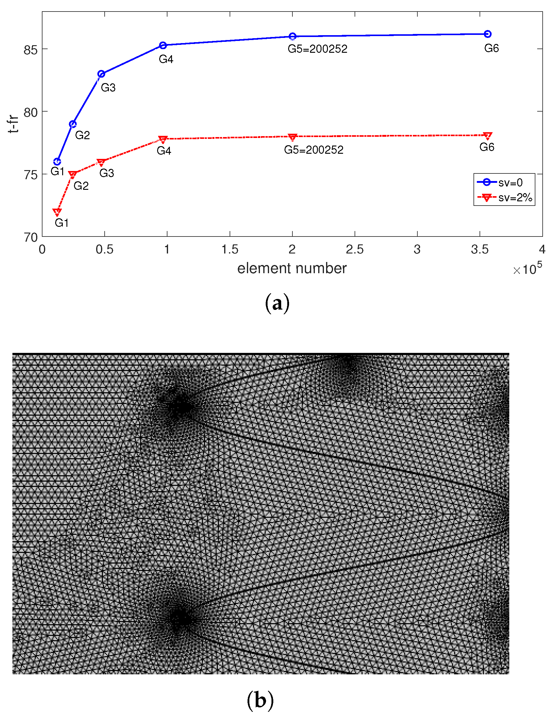
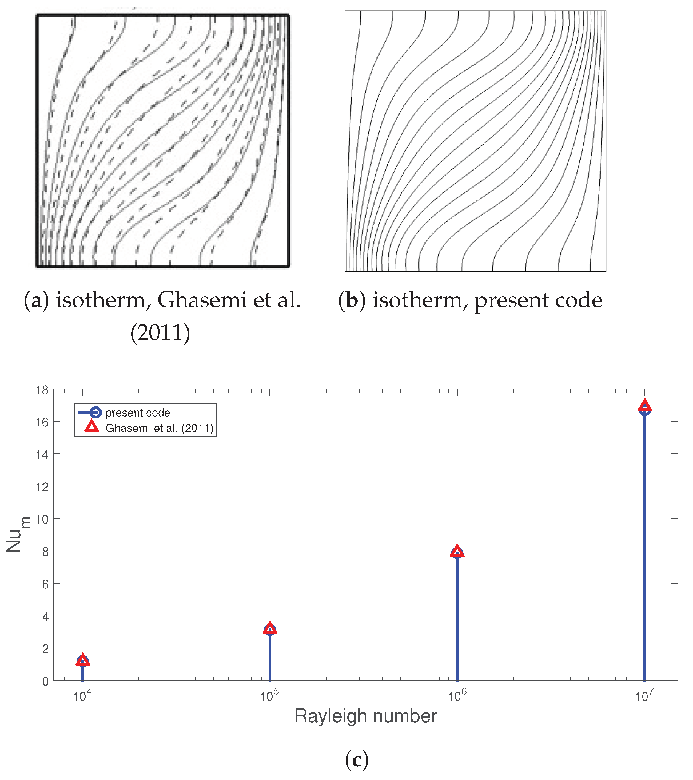
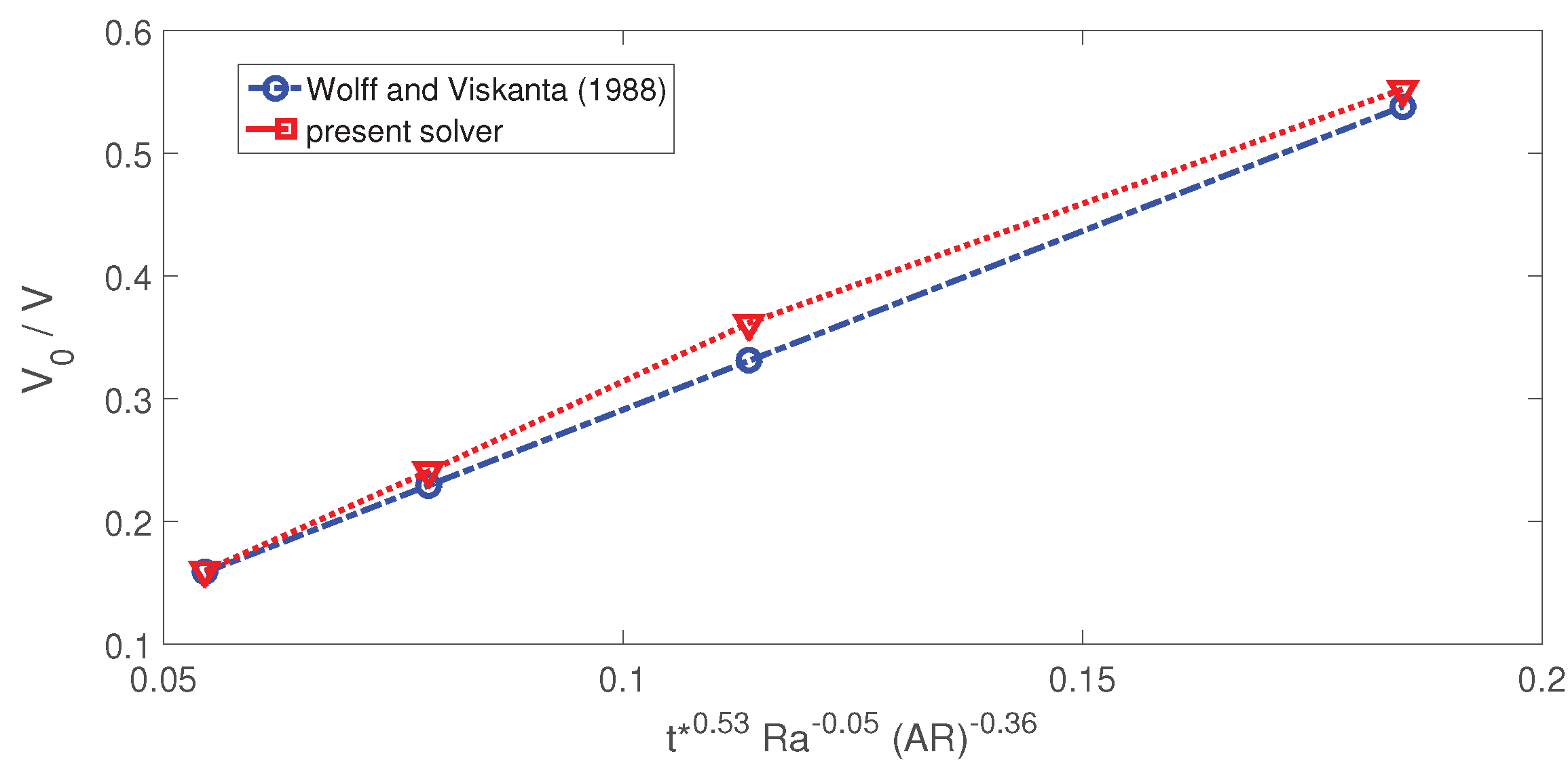
Tests are performed for achieving a suitable mesh distribution of the computational domain. Full phase change process time (t-fr) is compared using different grid sizes (from G1 to G5) at two different sv in Figure 3a. Grid system G5 with 200,252 number of elements is selected, and its distribution is given in Figure 3b. The refinement is made adjacent to the walls and interfaces. Validations tests are performed, and results are presented in Figure 4 and Figure 5. In the first test, convection in a heated cavity (differentially heated) is explored under MgF effects, as available in Ref. [58]. Comparison of isotherms at Ha = 60 is shown in Figure 4a,b; the thermal patterns are captured well with the present solver. Comparisons of average Nu versus Rayleigh number are given in Figure 4c. The highest deviation below 3% is obtained from the results. In another test, phase change process in a heated cavity is analyzed during convection using the results in Ref. [59]. They provided a correlation for the solidified volume fraction, which is a function of Rayleigh number (Ra), dimensionless time (t*), and aspect ratio of the cavity (AR). Figure 5 shows the comparison results; the highest deviation between the results is obtained as 9.2% at x-axis of 0.114. The present code can be used for simulation of phase change process under MgF effects.

3. Results and Discussion

Phase change and HT dynamics are explored in a VEN-C with multiple ports during nanofluid convection under impacts of partial MgF. A wavy shaped region of the PCM-PB is considered that has a sinusoidal wave form. The wave number is varied between 1 and 8, and the amplitude is between 0.01 H and 0.15 H. MgF is imposed in different domains, and the Ha values are varied between 0 and 50. Hybrid nanofluid is considered by dispersing binary particles of Ag-MgO in water with solid volume fraction (sv) up to 2%.
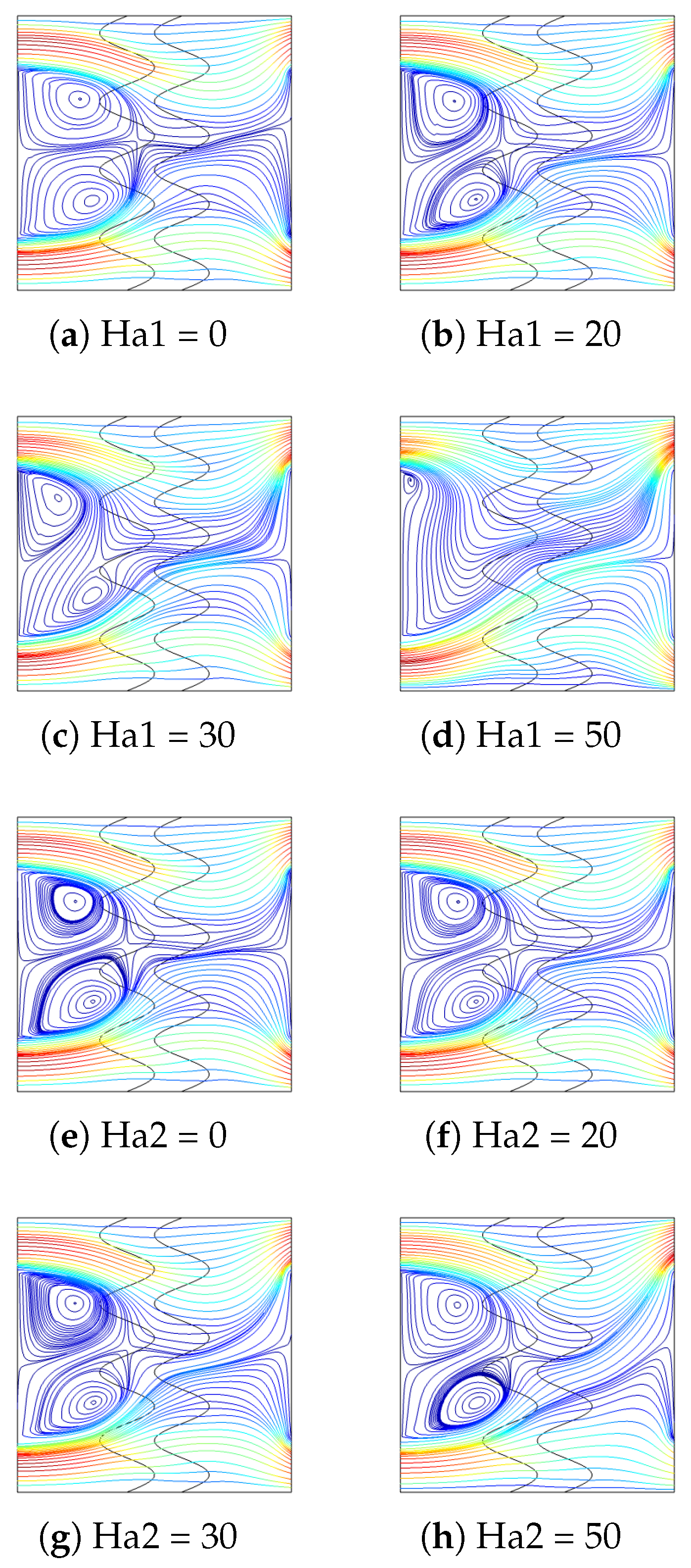
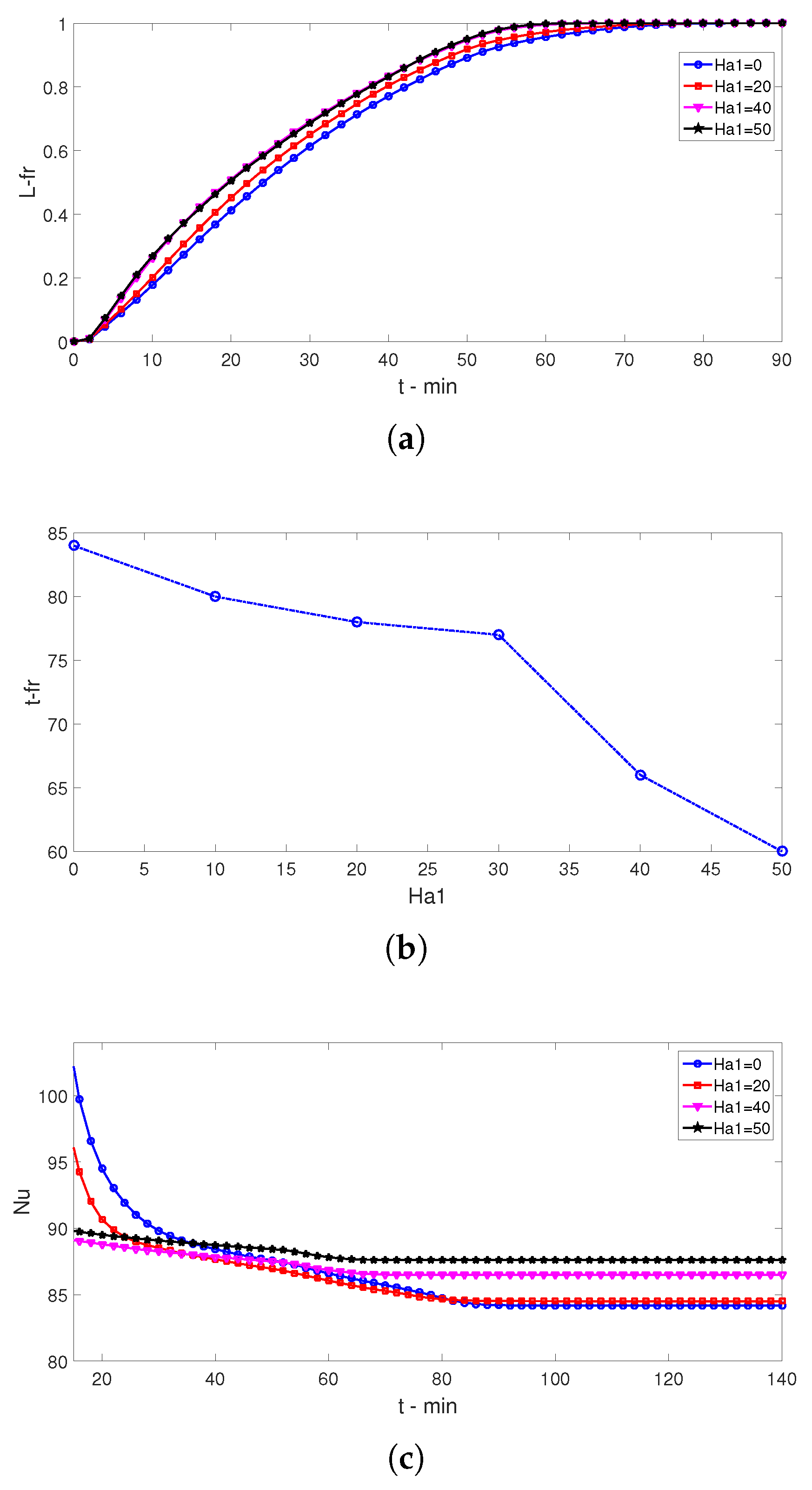
When MgF is absent in the first domain (Ha1 = 0), two vortices are formed below and above the inlet ports. As MgF is active, these vortices are reduced gradually and finally disappear at the highest strength (Ha1 = 50), as shown in Figure 6. As the strength of MgF related to second domain increases, flow patterns toward the exit port are influenced while the vortices near the inlet remains. The presence of second MgF only affects the HT dynamics, whereas its impact on the PC-P dynamics is marginal. Distribution of the liquid fraction (L-fr) for varying MgF strengths are shown in Figure 7. As the time evolves, the value of L-fr rises, but significant variations are seen when Mg filled with different strengths are active. The MgF is also used in the PCM-PB region while the fluid velocities near the walls and interfaces increases. In those regions, PC-P is fast, whereas in the interior domain, it may be lower due to the reduced fluid velocity. At t = 70 min, full phase transition is seen for the case withe the highest MgF strength, whereas in the absence of MgF, in the mid part of the wavy region, the value of L-fr is lower. When average L-fr is compared considering cases with different MgF strengths, PC-P dynamics are affected and are accelerated when the value of Ha1 rises. Complete transition time (t-fr in minutes) reduced with higher MgF strength, which is attributed to two facts. One is the suppression of the inlet vortices that are extending towards the PCM region, and the other is the velocity rise near the walls in the wavy zone with higher MgF strengths. A sharp reduction in t-fr is seen after Ha1 = 30. When varying Ha1 from Ha1 = 0 to Ha1 = 30, t-fr is reduced by only 8.3%, whereas it is reduced 22% from Ha1 = 30 to Ha1 = 50. The presence of MgF and its impact on the flow recirculation in the multi-port VEN-C is effective on the HT dynamics along with the PCM-PB region. In earlier times, the spatial average Nu is higher for the case without MgF, and its value rises by imposing MgF and increasing its strength after some time. The fluctuation in the average Nu is at a minimum when the MgF at the highest strength is imposed. The spatial average Nu is 9% higher (at t = 18 min), and it is 3.5% lower (t = 85 min) when cases at Ha1 = 0 and Ha1 = 50 are compared (Figure 8).
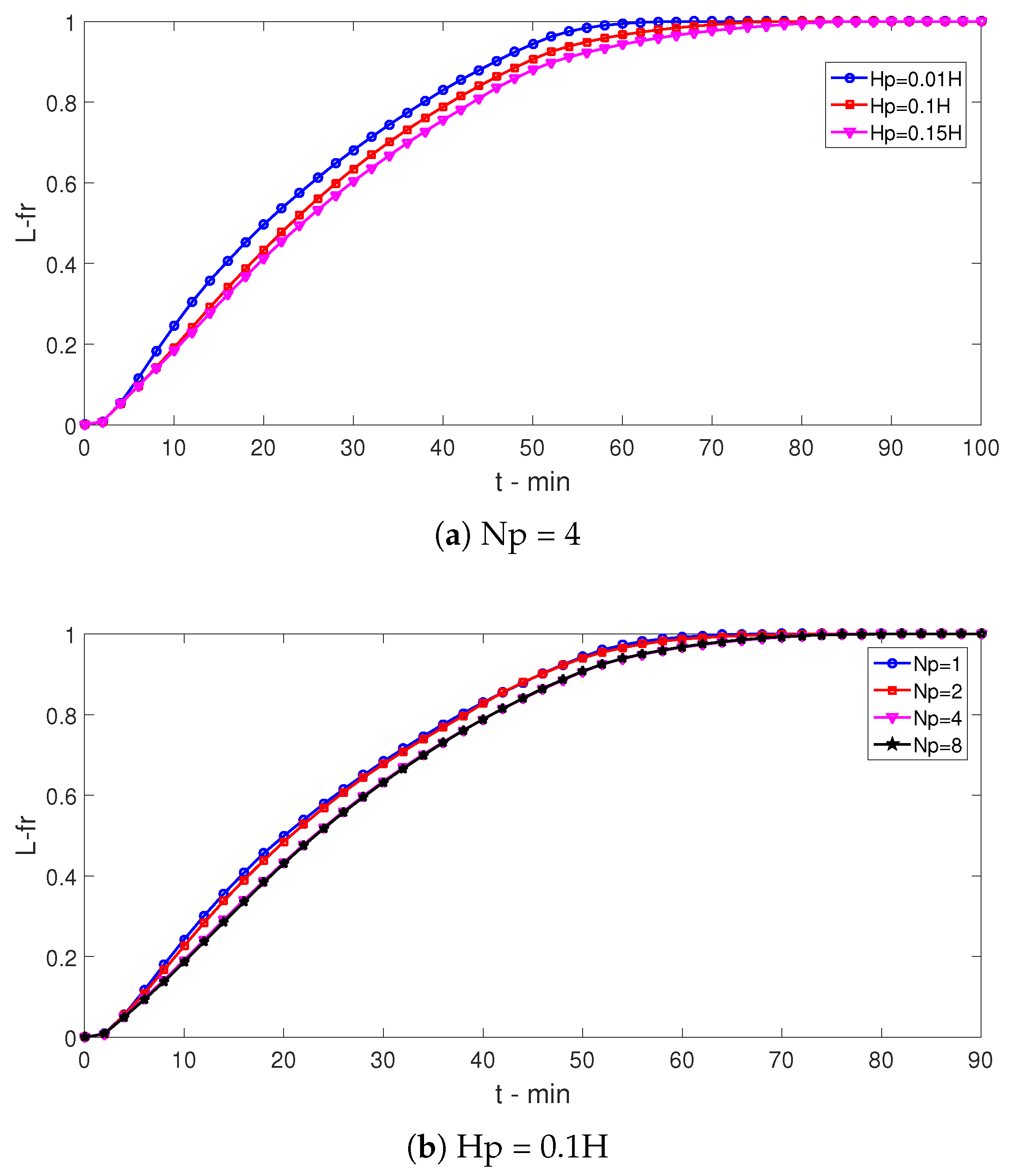
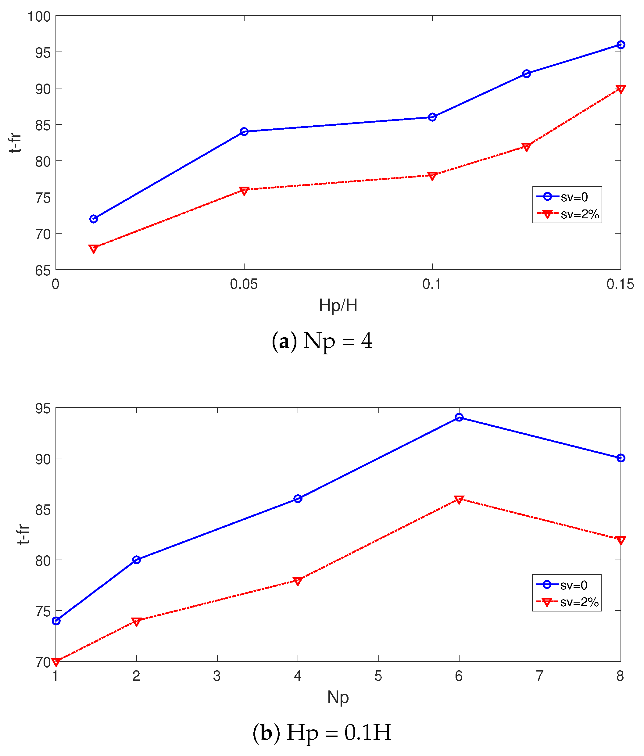
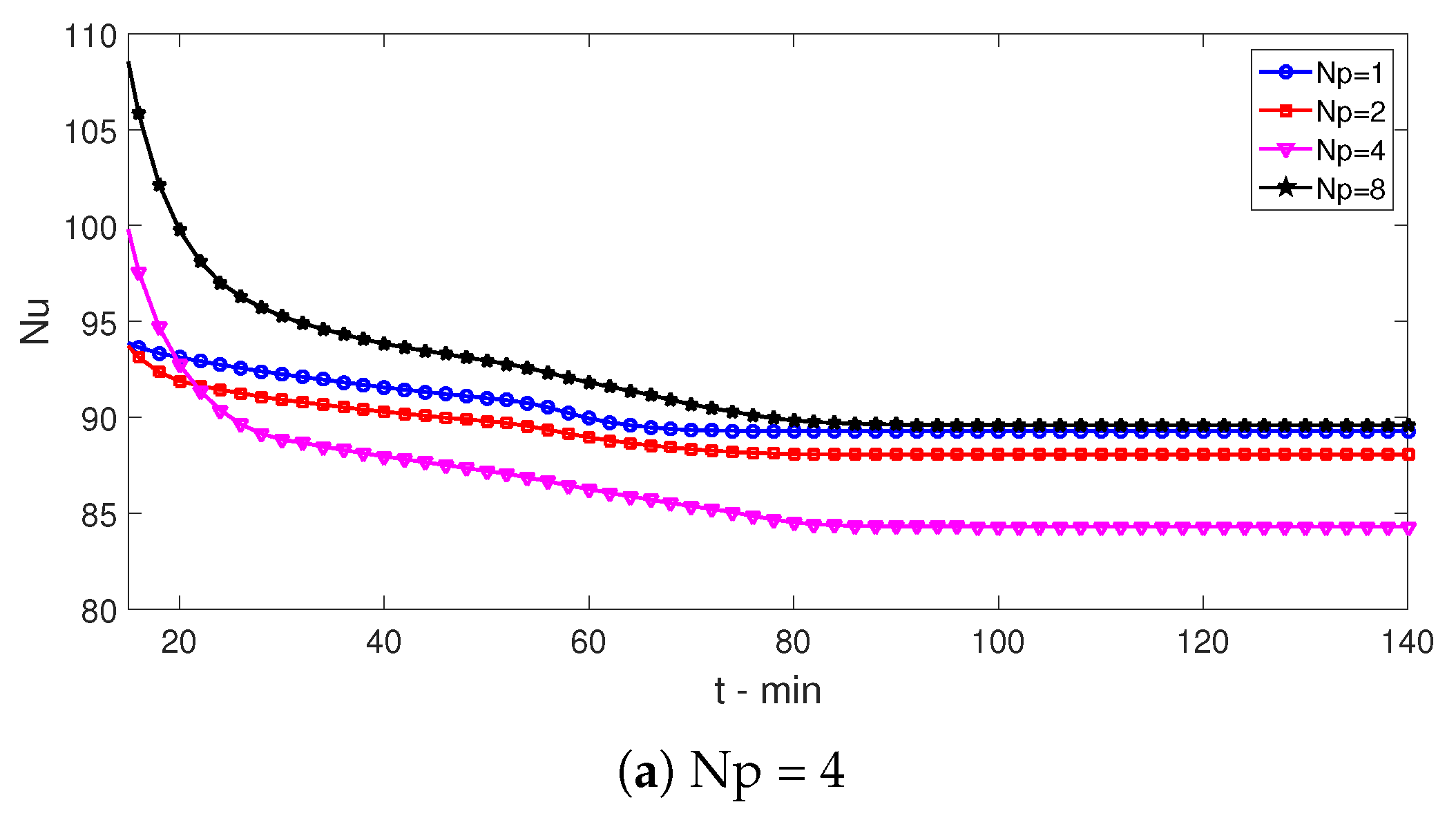
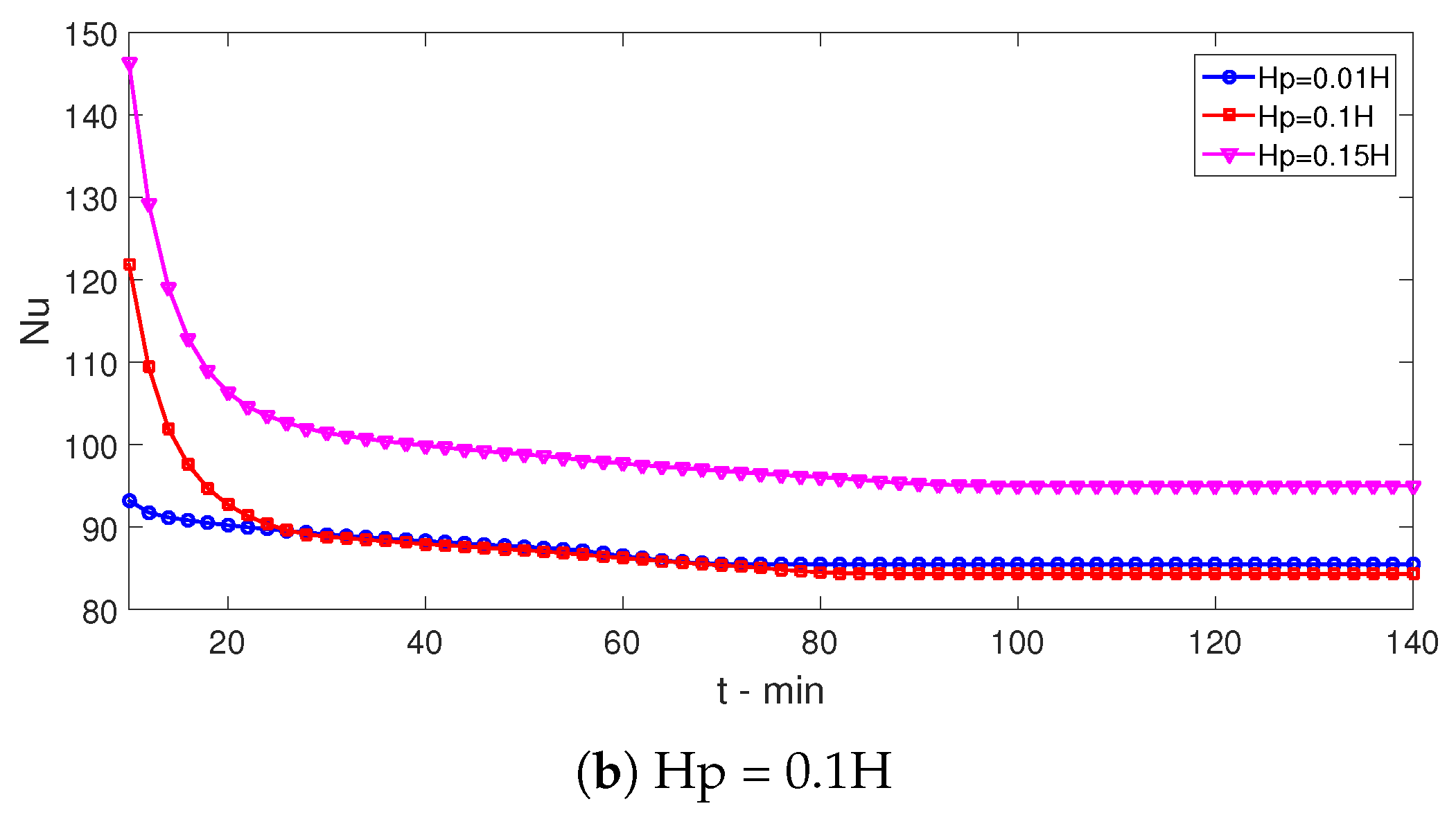
The wavy PCM-PB region parameters, such as amplitude and wave number, are influential on both the PC and HT dynamics. A sinusoidal wave form of the zone is assumed. The corrugation amplitude is varied between 0.01 H and 0.15 H, and wave number is between 1 and 8. Time dependent variations of L-fr for varying amplitude and wave numbers are presented in Figure 9. As the height of the corrugation is increased for a fixed wave number (Np = 4), more spherical capsules are used, and the L-fr amount is smaller for the same time. The wave number (Np) is also influential on the PC dynamics for a fixed amplitude (Hp = 0.1 H). As the number of waves is increased, the L-fr value is smaller for the same time instance, which is attributed to the balancing effects between the number of spherical capsules and thermal transport features with Np. The complete transition time (t-fr) rises with higher wave amplitudes for configurations using nanofluid and pure fluid. The increment amounts in the value of t-fr are obtained as 33% and 32% for pure fluid and nanofluid when Hp is increased from Hp = 0.01 H to Hp = 0.15 H (Figure 10). However, t-fr values are smaller when nanofluid is used instead of pure fluid due to the boosted thermal transport features from adding nanoparticles. When the number of waves is increased from Np = 1 to Np = 6, the value of t-fr rises, and the amount of increments are 21% and 23% for pure fluid and nanofluid cases. There is a 4.5% reduction of t-fr when Np is increased from 6 to 8 for both cases, which is attributed to the enhanced thermal transport. When HT is concerned, most favorable cases are achieved when a wavy zone with higher number of waves and amplitudes are used. At t = 20 min, spatial average Nu is 9% for the case with Np = 8 as compared to case Np = 1; variations between Nu of different amplitude cases reach 20% (Figure 11).
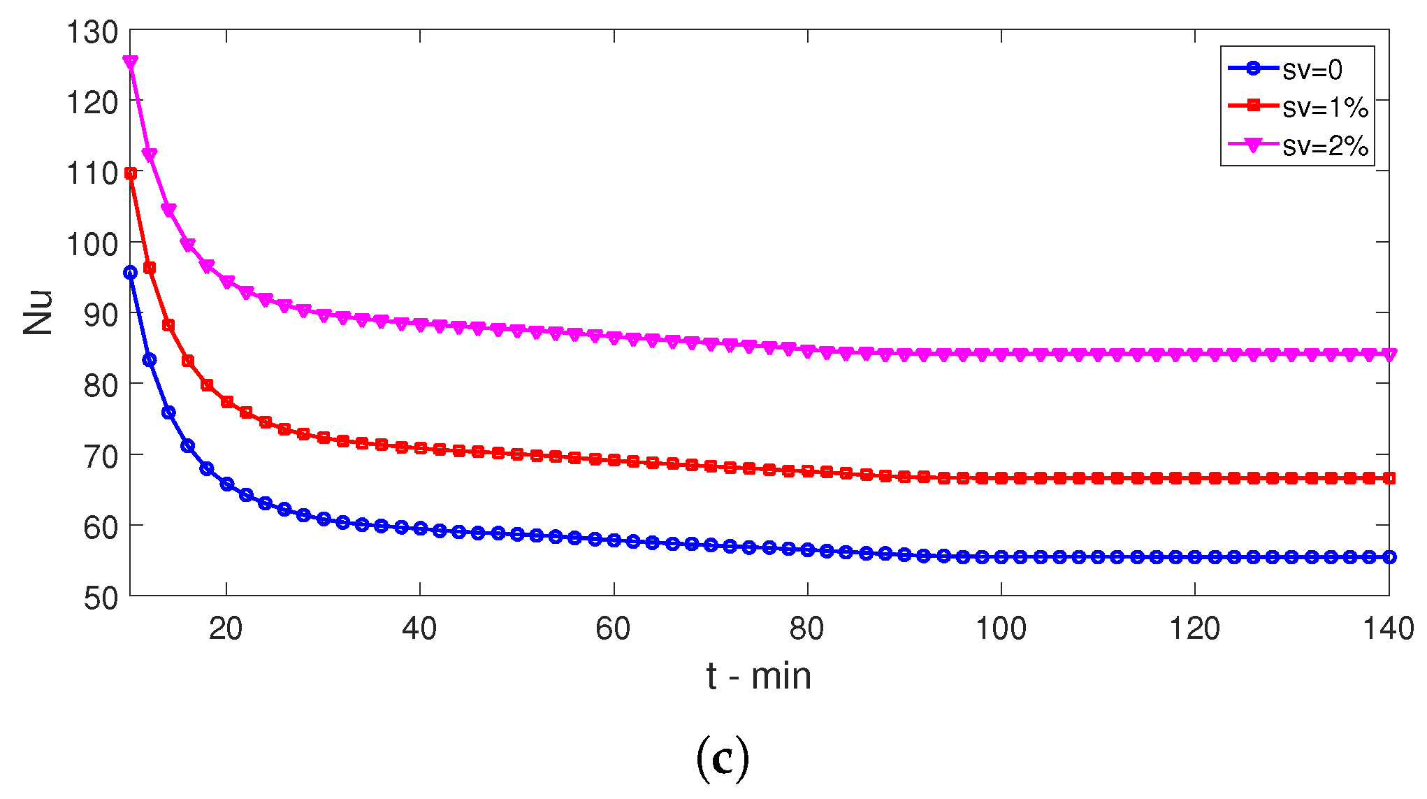
Nanoparticles are added in the base fluid for boosting the PC process and HT dynamics. Comparisons of L-fr distributions for various time instances between the cases of using pure fluid and nanofluid (sv = 2%) are shown in Figure 12. As the time evolves, L-fr amount rises; at t = 85 min, a complete phase transition is observed with nanofluid. The L-fr dynamics are influenced using nanofluid instead of pure fluid, and the L-fr amount becomes higher at the same time instance. The phase completion time is reduced with higher loading amount of nanoparticles (sv) in the absence and presence of MgF effects. The reduction amounts of t-fr are 13% and 15% for cases at Ha1 = 0 and Ha1 = 50. When the MgF effect is present in the PCM and VEN-C domains at the highest strength, vortex suppression in cavity and enhanced near wall region velocity are obtained in the PCM domain, which will accelerate the PC process, as shown before. When nanoparticles are used in the base fluid, the effectiveness of using MgF is increased due to the enhanced electrical conductivity and thermal transport features. When spatial average Nu values are compared, nanofluid with the highest nanopaticle loading provides the most favorable conditions. The spatial average Nu rises by about 20% and 55% at sv = 1% and sv = 2% as compared to pure fluid with sv = 0% (Figure 13).

4. Conclusions

Impacts of using a sinusoidal shaped PCM-PB system are explored in the phase change process and thermal performance of a VEN-C with multiple ports under partially active MgF effects during hybrid nanoliquid convection. The following conclusions are obtained:
  • When the MgF strength of the first domain rises, the PC-P process becomes fast due to the vortex suppression and rise of velocity in the near wall region. When the value of Ha1 rises from 0 to 30, reduction of t-fr is only 8.3%, whereas it is 22% when increasing Ha1 from 30 to 50.
  • When cases without (Ha1 = 0) and with (Ha1 = 50) MgF in the VEN-C are compared, the average Nu is 9% higher at t = 18 min and 3.5% lower at t = 85 min.
  • When wave amplitude rises, complete transition time (t-fr) increases for nanofluid and pure fluid cases. The amount of the rise is about 33% when Hp rises from 0.01 H to 0.15 H. When wave number rises from Np = 1 to Np = 6, t-fr increases by about 23% with nanofluid as the HT fluid.
  • Most favorable cases in terms of HT are obtained with higher amplitude and wave number. When wave amplitude rises, up to a 20% rise of HT is obtained at t = 20 min.
  • When nanofluids are used, phase change is accelerated and thermal performance is also improved. Phase change process time is reduced by 15% at the highest nanoparticle loading as compared to the case with pure fluid while spatial average Nu rises by about 55%.
  • The wavy shape of the PCM-PB region and varying its geometrical form provide good control opportunity for the phase change process and thermal performance improvement.

Author Contributions

Conceptualization, F.S.; methodology, F.S. and H.F.Ö.; software, F.S.; validation, H.F.Ö.; formal analysis, F.S. and H.F.Ö.; investigation, F.S. and H.F.Ö.; writing—original draft preparation, F.S.; writing—review and editing, F.S. and H.F.Ö.; visualization, F.S. and H.F.Ö.; supervision, F.S. and H.F.Ö. All authors have read and agreed to the published version of the manuscript.

Funding

This research received no external funding.

Institutional Review Board Statement

Not applicable.

Informed Consent Statement

Not applicable.

Conflicts of Interest

The authors declare no conflict of interest.

Abbreviations

Hcavity size
HaHartmann number
Hpwave amplitude
kthermal conductivity
L f latent heat of fusion
L-frliquid fraction
nunit normal vector
Npwave number
NuNusselt number
ppressure
PrPrandtl number
ReReynolds number
ttime
t-frcomplete transition time
Ttemperature
T m melting temperature
w i inlet port size
w o outlet port size
u, vvelocity components
Greek Characters
ν kinematic viscosity
ρ density of the fluid
ε p porosity
κ permeability
ϕ solid volume fraction
γ magnetic field inclination
Subscripts
ccold
hhot
maverage
nfnanofluid
psolid particle
Abbreviations
FEMfinite element method
HTheat transfer
MgFmagnetic field
PBpacked bed
PCMphase change material
VEN-Cvented cavity

References

  1. Saeidi, S.; Khodadadi, J. Transient flow and heat transfer leading to periodic state in a cavity with inlet and outlet ports due to incoming flow oscillation. Int. J. Heat Mass Transf. 2007, 50, 530–538. [Google Scholar] [CrossRef]
  2. Ismael, M.A.; Jasim, H.F. Role of the fluid-structure interaction in mixed convection in a vented cavity. Int. J. Mech. Sci. 2018, 135, 190–202. [Google Scholar] [CrossRef]
  3. Saeidi, S.; Khodadadi, J. Forced convection in a square cavity with inlet and outlet ports. Int. J. Heat Mass Transf. 2006, 49, 1896–1906. [Google Scholar] [CrossRef]
  4. Selimefendigil, F.; Öztop, H.F. Fluid-solid interaction of elastic-step type corrugation effects on the mixed convection of nanofluid in a vented cavity with magnetic field. Int. J. Mech. Sci. 2019, 152, 185–197. [Google Scholar] [CrossRef]
  5. Shih, Y.C.; Khodadadi, J.; Nien, S.W.; Zeng, Y.; Huang, X.L. Impact of an oscillating guide vane on the thermo-hydraulic fields in a square cavity with single inlet and outlet ports. Int. J. Heat Mass Transf. 2019, 128, 1184–1200. [Google Scholar] [CrossRef]
  6. Selimefendigil, F.; Öztop, H.F. Magnetohydrodynamics forced convection of nanofluid in multi-layered U-shaped vented cavity with a porous region considering wall corrugation effects. Int. Commun. Heat Mass Transf. 2020, 113, 104551. [Google Scholar] [CrossRef]
  7. Hamzah, H.; Canpolat, C.; Jasim, L.M.; Sahin, B. Hydrothermal index and entropy generation of a heated cylinder placed between two oppositely rotating cylinders in a vented cavity. Int. J. Mech. Sci. 2021, 201, 106465. [Google Scholar] [CrossRef]
  8. Sheikholeslami, M.; Rokni, H.B. Simulation of nanofluid heat transfer in presence of magnetic field: A review. Int. J. Heat Mass Transf. 2017, 115, 1203–1233. [Google Scholar] [CrossRef]
  9. Kabeel, A.; El-Said, E.M.; Dafea, S. A review of magnetic field effects on flow and heat transfer in liquids: Present status and future potential for studies and applications. Renew. Sustain. Energy Rev. 2015, 45, 830–837. [Google Scholar] [CrossRef]
  10. Alghamdi, W.; Alsubie, A.; Kumam, P.; Saeed, A.; Gul, T. MHD hybrid nanofluid flow comprising the medication through a blood artery. Sci. Rep. 2021, 11, 11621. [Google Scholar] [CrossRef]
  11. Kefayati, G.R. Simulation of heat transfer and entropy generation of MHD natural convection of non-Newtonian nanofluid in an enclosure. Int. J. Heat Mass Transf. 2016, 92, 1066–1089. [Google Scholar] [CrossRef]
  12. Abbassi, H.; Nassrallah, S.B. MHD flow and heat transfer in a backward-facing step. Int. Commun. Heat Mass Transf. 2007, 34, 231–237. [Google Scholar] [CrossRef]
  13. Benzema, M.; Benkahla, Y.K.; Labsi, N.; Ouyahia, S.E.; El Ganaoui, M. Second law analysis of MHD mixed convection heat transfer in a vented irregular cavity filled with Ag–MgO/water hybrid nanofluid. J. Therm. Anal. Calorim. 2019, 137, 1113–1132. [Google Scholar] [CrossRef]
  14. Selimefendigil, F.; Chamkha, A.J. MHD mixed convection of nanofluid in a three-dimensional vented cavity with surface corrugation and inner rotating cylinder. Int. J. Numer. Methods Heat Fluid Flow 2019, 30, 1637–1660. [Google Scholar] [CrossRef]
  15. Ali, H.M.; Arshad, W. Effect of channel angle of pin-fin heat sink on heat transfer performance using water based graphene nanoplatelets nanofluids. Int. J. Heat Mass Transf. 2017, 106, 465–472. [Google Scholar] [CrossRef]
  16. Baïri, A. Experimental study on enhancement of free convective heat transfer in a tilted hemispherical enclosure by using Water-ZnO nanofluid saturated porous materials. Appl. Therm. Eng. 2019, 148, 992–998. [Google Scholar] [CrossRef]
  17. Esfe, M.H.; Esfandeh, S.; Saedodin, S.; Rostamian, H. Experimental evaluation, sensitivity analyzation and ANN modeling of thermal conductivity of ZnO-MWCNT/EG-water hybrid nanofluid for engineering applications. Appl. Therm. Eng. 2017, 125, 673–685. [Google Scholar] [CrossRef]
  18. Kakaç, S.; Pramuanjaroenkij, A. Review of convective heat transfer enhancement with nanofluids. Int. J. Heat Mass Transf. 2009, 52, 3187–3196. [Google Scholar] [CrossRef]
  19. Kasaeian, A.; Daneshazarian, R.; Mahian, O.; Kolsi, L.; Chamkha, A.J.; Wongwises, S.; Pop, I. Nanofluid flow and heat transfer in porous media: A review of the latest developments. Int. J. Heat Mass Transf. 2017, 107, 778–791. [Google Scholar] [CrossRef]
  20. Bashirnezhad, K.; Bazri, S.; Safaei, M.R.; Goodarzi, M.; Dahari, M.; Mahian, O.; Dalkılıça, A.S.; Wongwises, S. Viscosity of nanofluids: A review of recent experimental studies. Int. Commun. Heat Mass Transf. 2016, 73, 114–123. [Google Scholar] [CrossRef]
  21. Chamkha, A.J.; Jena, S.K.; Mahapatra, S.K. MHD convection of nanofluids: A review. J. Nanofluids 2015, 4, 271–292. [Google Scholar] [CrossRef]
  22. Izadi, A.; Siavashi, M.; Rasam, H.; Xiong, Q. MHD enhanced nanofluid mediated heat transfer in porous metal for CPU cooling. Appl. Therm. Eng. 2020, 168, 114843. [Google Scholar] [CrossRef]
  23. Selimefendigil, F.; Öztop, H.F. MHD Pulsating forced convection of nanofluid over parallel plates with blocks in a channel. Int. J. Mech. Sci. 2019, 157, 726–740. [Google Scholar] [CrossRef]
  24. Sajjadi, H.; Delouei, A.A.; Izadi, M.; Mohebbi, R. Investigation of MHD natural convection in a porous media by double MRT lattice Boltzmann method utilizing MWCNT–Fe3O4/water hybrid nanofluid. Int. J. Heat Mass Transf. 2019, 132, 1087–1104. [Google Scholar] [CrossRef]
  25. Cabeza, L.F.; Castell, A.; Barreneche, C.d.; De Gracia, A.; Fernández, A. Materials used as PCM in thermal energy storage in buildings: A review. Renew. Sustain. Energy Rev. 2011, 15, 1675–1695. [Google Scholar] [CrossRef]
  26. Ebadi, S.; Tasnim, S.H.; Aliabadi, A.A.; Mahmud, S. Melting of nano-PCM inside a cylindrical thermal energy storage system: Numerical study with experimental verification. Energy Convers. Manag. 2018, 166, 241–259. [Google Scholar] [CrossRef]
  27. Mat, S.; Al-Abidi, A.A.; Sopian, K.; Sulaiman, M.Y.; Mohammad, A.T. Enhance heat transfer for PCM melting in triplex tube with internal–external fins. Energy Convers. Manag. 2013, 74, 223–236. [Google Scholar] [CrossRef]
  28. Sheikholeslami, M. Numerical modeling of nano enhanced PCM solidification in an enclosure with metallic fin. J. Mol. Liq. 2018, 259, 424–438. [Google Scholar] [CrossRef]
  29. Madruga, S.; Mendoza, C. Heat transfer performance and thermal energy storage in nano-enhanced phase change materials driven by thermocapillarity. Int. Commun. Heat Mass Transf. 2021, 129, 105672. [Google Scholar] [CrossRef]
  30. Zhao, C.; Opolot, M.; Liu, M.; Bruno, F.; Mancin, S.; Hooman, K. Numerical study of melting performance enhancement for PCM in an annular enclosure with internal-external fins and metal foams. Int. J. Heat Mass Transf. 2020, 150, 119348. [Google Scholar] [CrossRef]
  31. Madruga, S.; Mischlich, G.S. Melting dynamics of a phase change material (PCM) with dispersed metallic nanoparticles using transport coefficients from empirical and mean field models. Appl. Therm. Eng. 2017, 124, 1123–1133. [Google Scholar] [CrossRef] [Green Version]
  32. Al-Jethelah, M.; Tasnim, S.H.; Mahmud, S.; Dutta, A. Nano-PCM filled energy storage system for solar-thermal applications. Renew. Energy 2018, 126, 137–155. [Google Scholar] [CrossRef]
  33. Kasaeian, A.; Bahrami, L.; Pourfayaz, F.; Khodabandeh, E.; Yan, W.M. Experimental studies on the applications of PCMs and nano-PCMs in buildings: A critical review. Energy Build. 2017, 154, 96–112. [Google Scholar] [CrossRef]
  34. Khodadadi, J.; Hosseinizadeh, S. Nanoparticle-enhanced phase change materials (NEPCM) with great potential for improved thermal energy storage. Int. Commun. Heat Mass Transf. 2007, 34, 534–543. [Google Scholar] [CrossRef]
  35. Rostami, S.; Afrand, M.; Shahsavar, A.; Sheikholeslami, M.; Kalbasi, R.; Aghakhani, S.; Shadloo, M.S.; Oztop, H.F. A review of melting and freezing processes of PCM/nano-PCM and their application in energy storage. Energy 2020, 211, 118698. [Google Scholar] [CrossRef]
  36. Selimefendigil, F.; Öztop, H.F. Analysis of hybrid nanofluid and surface corrugation in the laminar convective flow through an encapsulated PCM filled vertical cylinder and POD-based modeling. Int. J. Heat Mass Transf. 2021, 178, 121623. [Google Scholar] [CrossRef]
  37. Regin, A.F.; Solanki, S.; Saini, J. Heat transfer characteristics of thermal energy storage system using PCM capsules: A review. Renew. Sustain. Energy Rev. 2008, 12, 2438–2458. [Google Scholar] [CrossRef]
  38. Singh, H.; Saini, R.; Saini, J. A review on packed bed solar energy storage systems. Renew. Sustain. Energy Rev. 2010, 14, 1059–1069. [Google Scholar] [CrossRef]
  39. de Gracia, A.; Cabeza, L.F. Numerical simulation of a PCM packed bed system: A review. Renew. Sustain. Energy Rev. 2017, 69, 1055–1063. [Google Scholar] [CrossRef] [Green Version]
  40. Karthikeyan, S.; Velraj, R. Numerical investigation of packed bed storage unit filled with PCM encapsulated spherical containers—A comparison between various mathematical models. Int. J. Therm. Sci. 2012, 60, 153–160. [Google Scholar] [CrossRef]
  41. Regin, A.F.; Solanki, S.; Saini, J. An analysis of a packed bed latent heat thermal energy storage system using PCM capsules: Numerical investigation. Renew. Energy 2009, 34, 1765–1773. [Google Scholar] [CrossRef]
  42. Ghalambaz, M.; Zadeh, S.M.H.; Mehryan, S.; Pop, I.; Wen, D. Analysis of melting behavior of PCMs in a cavity subject to a non-uniform magnetic field using a moving grid technique. Appl. Math. Model. 2020, 77, 1936–1953. [Google Scholar] [CrossRef]
  43. Kohyani, M.T.; Ghasemi, B.; Raisi, A.; Aminossadati, S. Melting of cyclohexane–Cu nano-phase change material (nano-PCM) in porous medium under magnetic field. J. Taiwan Inst. Chem. Eng. 2017, 77, 142–151. [Google Scholar] [CrossRef]
  44. Ghachem, K.; Selimefendigil, F.; Öztop, H.F.; Almeshaal, M.; Alhadri, M.; Kolsi, L. Effects of magnetic field, binary particle loading and rotational conic surface on phase change process in a PCM filled cylinder. Case Stud. Therm. Eng. 2021, 28, 101456. [Google Scholar] [CrossRef]
  45. Gibanov, N.S.; Sheremet, M.A.; Oztop, H.F.; Abu-Hamdeh, N. Effect of uniform inclined magnetic field on mixed convection in a lid-driven cavity having a horizontal porous layer saturated with a ferrofluid. Int. J. Heat Mass Transf. 2017, 114, 1086–1097. [Google Scholar] [CrossRef]
  46. Cimpean, D.; Sheremet, M.; Pop, I. Mixed convection of hybrid nanofluid in a porous trapezoidal chamber. Int. Commun. Heat Mass Transf. 2020, 116, 104627. [Google Scholar] [CrossRef]
  47. Mohammadnejad, F.; Hossainpour, S. A CFD modeling and investigation of a packed bed of high temperature phase change materials (PCMs) with different layer configurations. J. Energy Storage 2020, 28, 101209. [Google Scholar] [CrossRef]
  48. Nield, D.; Bejan, A. Convection in Porous Media. In Convection Heat Transfer; John Wiley & Sons, Inc.: Hoboken, NJ, USA, 2013. [Google Scholar]
  49. Comsol. Comsol User’s Guide; Comsol AB: Stockholm, Sweden, 2018. [Google Scholar]
  50. Wakao, N.; Kaguei, S.; Funazkri, T. Effect of fluid dispersion coefficients on particle-to-fluid heat transfer coefficients in packed beds: Correlation of Nusselt numbers. Chem. Eng. Sci. 1979, 34, 325–336. [Google Scholar] [CrossRef]
  51. Esfe, M.H.; Arani, A.A.A.; Rezaie, M.; Yan, W.M.; Karimipour, A. Experimental determination of thermal conductivity and dynamic viscosity of Ag–MgO/water hybrid nanofluid. Int. Commun. Heat Mass Transf. 2015, 66, 189–195. [Google Scholar] [CrossRef]
  52. Nallusamy, N.; Sampath, S.; Velraj, R. Experimental investigation on a combined sensible and latent heat storage system integrated with constant/varying (solar) heat sources. Renew. Energy 2007, 32, 1206–1227. [Google Scholar] [CrossRef]
  53. Lewis, R.W.; Nithiarasu, P.; Seetharamu, K.N. Fundamentals of the Finite Element Method for Heat and Fluid Flow; John Wiley & Sons: West Sussex, UK, 2004. [Google Scholar]
  54. Reddy, J.N.; Gartling, D.K. The Finite Element Method in Heat Transfer and Fluid Dynamics; CRC Press: Boca Raton, FL, USA, 2010. [Google Scholar]
  55. Rahman, M.M.; Parvin, S.; Rahim, N.; Islam, M.; Saidur, R.; Hasanuzzaman, M. Effects of Reynolds and Prandtl number on mixed convection in a ventilated cavity with a heat-generating solid circular block. Appl. Math. Model. 2012, 36, 2056–2066. [Google Scholar] [CrossRef]
  56. Ullah, N.; Nadeem, S.; Saleem, A. Finite element analysis of convective nanofluid equipped in enclosure having both inlet and outlet zones. J. Taiwan Inst. Chem. Eng. 2020, 113, 428–441. [Google Scholar] [CrossRef]
  57. Selimefendigil, F.; Öztop, H.F. Forced convection of ferrofluids in a vented cavity with a rotating cylinder. Int. J. Therm. Sci. 2014, 86, 258–275. [Google Scholar] [CrossRef]
  58. Ghasemi, B.; Aminossadati, S.; Raisi, A. Magnetic field effect on natural convection in a nanofluid-filled square enclosure. Int. J. Therm. Sci. 2011, 50, 1748–1756. [Google Scholar] [CrossRef]
  59. Wolff, F.; Viskanta, R. Solidification of a pure metal at a vertical wall in the presence of liquid superheat. Int. J. Heat Mass Transf. 1988, 31, 1735–1744. [Google Scholar] [CrossRef]
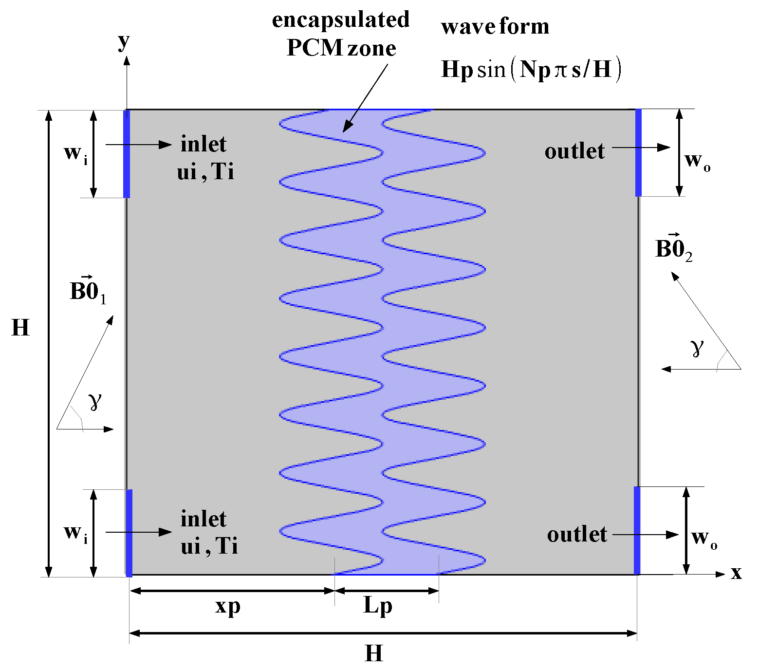
Figure 1. Schematic view of multi-port Ve-C with wavy PCM-PB zone.
Magnetochemistry 08 00190 g001
Figure 2. Different wave forms of the PCM-PB region.
Magnetochemistry 08 00190 g002
Figure 3. Grid independence test: PC-time versus element number at two different sv of nanoparticles (a) (Ha1 = Ha2 = 15, Np = 4, Hp = 0.1 H) and grid distributions (b).
Magnetochemistry 08 00190 g003
Figure 4. Comparison of isotherms in a heated cavity under MgF at Ha = 50 (a,b) and average Nu versus Rayleigh number under MgF at Ha = 30 (c) using the results in Ref. [58].
Magnetochemistry 08 00190 g004
Figure 5. Solidified volume fraction comparisons during phase change in a heated cavity using the results in Ref. [59].
Magnetochemistry 08 00190 g005
Figure 6. Effects of MgF strength of different domains on the distribution of streamlines (Np = 4, Hp = 0.1 H, sv = 2%).
Magnetochemistry 08 00190 g006
Figure 7. The L-fr distributions with varying MgF strengths of different domains (Np = 4, Hp = 0.1 H, sv = 2%).
Magnetochemistry 08 00190 g007
Figure 8. Impacts of MgF strength on the variation of time dependent L-Fr (a), PC time (b), and spatial average Nu (c) (Np = 4, Hp = 0.1 H, sv = 2%).
Magnetochemistry 08 00190 g008
Figure 9. Effects of wavy PCM-zone height (a) and wave number (b) on the variation of L-Fr (Ha1 = Ha2 = 15, sv = 2%).
Magnetochemistry 08 00190 g009
Figure 10. PC-time versus height (a) and versus wave number (b) of wavy PCM-zone (Ha1 = Ha2 = 15, sv = 2%).
Magnetochemistry 08 00190 g010
Figure 11. Time dependent Nu variations for different height (a) and wave number (b) of wavy PCM-zone (Ha1 = Ha2 = 15, sv = 2%).
Magnetochemistry 08 00190 g011aMagnetochemistry 08 00190 g011b
Figure 12. The L-fr distributions at two different sv of nanoparticles used in the base fluid for different time instances (Ha1 = Ha2 = 15, Np = 4, Hp = 0.1 H).
Magnetochemistry 08 00190 g012
Figure 13. Effects of sv of nanoparticles on the variation of L-fr (a), PC-time (b), and spatial average Nu (c) (Ha1 = Ha2 = 15, Np = 4, Hp = 0.1 H).
Magnetochemistry 08 00190 g013aMagnetochemistry 08 00190 g013b
Table 1. Thermophysical properties of PCM [52].
PropertyValue
Density-solid ( ρ , kg/m3)861
Density-liquid ( ρ , kg/m3)778
Specific heat-solid (Cp, J/kg °C)1850
Specific heat-fluid (Cp, J/kg °C)2384
Thermal conductivity-solid (k, W/m °C)0.40
Thermal conductivity-fluid (k, W/m °C)0.15
Melting temperature (Tm, °C)60
Latent heat of fusion (L, kJ/kg)213
Publisher’s Note: MDPI stays neutral with regard to jurisdictional claims in published maps and institutional affiliations.