Abstract
Saccharina japonica (known as Laminaria japonica or Phaeophyta japonica), one of the largest macroalgae, has been recognized as food and medicine for a long time in some Asian countries, such as China, South Korea, Japan, etc. In recent years, S. japonica has also been considered the most promising third-generation biofuel feedstock to replace fossil fuels, contributing to solving the challenges people face regarding energy and the environment. In particular, S. japonica-derived biohydrogen (H2) is expected to be a major fuel source in the future because of its clean, high-yield, and sustainable properties. Therefore, this review focuses on recent advances in bio-H2 production from S. japonica. The cutting-edge biological technologies with suitable operating parameters to enhance S. japonica’s bio-H2 production efficiency are reviewed based on the Scopus database. In addition, guidelines for future developments in this field are discussed.
1. Introduction
1.1. The Importance of Biohydrogen Production
Nowadays, energy and environmental issues such as energy crises, environmental pollution, global warming, climate change, etc., are some of the biggest challenges faced by modern society [1,2]. The most commonly used fuel, fossil fuels, which have played a vital role in the development of society and industry, are gradually depleting. More seriously, carbon dioxide (CO2), a primary greenhouse gas, is emitted from fossil fuel combustion, which is directly related to global warming and causes severe adverse effects on the habitat and health of humans and animals [3,4]. Therefore, finding renewable and carbon neutral energy sources to substitute for fossil fuels has become urgent and necessary.
Hydrogen (H2) has been determined as an excellent substitution for fossil fuels that has many benefits when compared to other alternative sources of energy, such as (i) the product when burning H2 is only water vapors, which, obviously, will not cause any adverse effects on the environment; (ii) additionally, H2 has the highest mass-specific energy among the gas fuels. The energy content of H2 is 120 kJ/g compared to 50 kJ/g for CH4, 44 kJ/g for gasoline, and 26.8 kJ/g for ethanol [5]; (iii) moreover, H2 can be obtained from a wide diversity of sources, even waste, so that it can be eco-friendly, cost-effective, renewable, and sustainable [6]. Therefore, H2 is increasingly being produced and widely used, with tens of millions of tons of H2 produced each year globally, primarily for large-scale industrial use [7]. Especially with the increase in human awareness of the energy and environmental issues mentioned above, H2 is considered vital in using new energy and reducing greenhouse gas emissions [7,8].
On an industrial scale, the most popular methods of H2 production are hydrocarbon reforming, pyrolysis of hydrocarbons, water splitting, etc. [9,10]. However, such methods are costly and energy-intensive, and even the primary material in most of these processes is still from fossil fuel, which causes H2 production not to be considered an alternative energy source. Therefore, it is essential to develop cost-effective production methods while identifying widespread and cheaper sources of materials so H2 can become more economical.
Recently, biohydrogen production from biomass has been gaining attention and is considered a cost-effective H2 production process due to biomass being a renewable primary energy source that is derived from plant and animal materials, especially by-products from them such as crop and industrial residues, animal and municipal waste, etc. [11]. The conversion of biomass into H2 is shown in Figure 1 and classified into two main groups, including (i) thermochemical processes (pyrolysis, gasification, combustion, and liquefaction) and (ii) biological conversions or bio-H2 production (fermentation, photolysis, etc.).
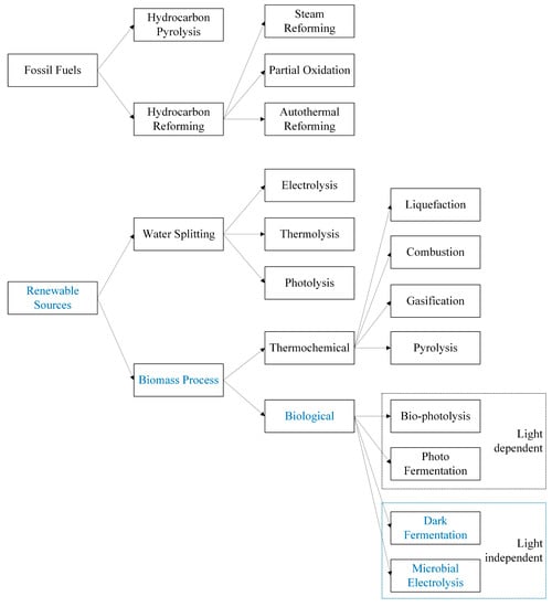
Figure 1.
H2 production methods.
Group (i) methods are effective, but they require a high amount of energy to operate, reducing the cost-effectiveness of H2 production. Meanwhile, H2 production via biological methods in group (ii) is considered the most cost-effective process [12]. The great benefit of biological processes is that they can be performed at an ambient pressure and temperature compared to other processes, which are performed under relatively harsh conditions [10]. Bio-H2 production processes can be classified as (i) light-independent processes (including dark fermentation (DF) and microbial electrolysis cell (MEC)) and (ii) light-dependent processes (including photo fermentation and bio-photolysis). Obviously, light-independent processes are a great option for bio-H2 production.
1.2. Potential and Benefits of Biohydrogen Production from Macroalgae
In order to replace fossil fuels, the use of energy from terrestrial biomass requires significant crop production areas to be able to ensure an adequate supply of raw materials [13]. It is estimated that if all of the lands on Earth are used, biomass harvesting can ultimately support the use of basic human energy [13]. However, this is difficult to realize because the available land for biomass cultivation is limited by some specific areas, such as deserts, preserved rainforests, etc., especially croplands [14]. However, there have been many attempts to use non-food terrestrial biomass, for example, agricultural wastes, as feedstocks to reduce cost and avoid competition between energy and food. However, the recovery yields and productivities are still not high due to the efficient conversion of recalcitrant lignocellulose to release sugar remaining a significant impediment to current technologies [14,15].
As a result, the ocean and its biomass resources will be a great option to overcome these constraints from terrestrial biomass. Oceans with large areas not limited by water and temperature have outstanding advantages over terrestrial environments. As with terrestrial biomass, ocean-derived biomass has the potential to become a feedstock for conversion into energy [16]. In addition, marine biomass used as a raw material source for bio-H2 production has recently raised awareness because of its high productivity and availability. Moreover, developing techniques for aquaculture and processing marine biomass on a large scale will contribute to developing natural seafood and fish populations. However, this energy source from marine biomass has not yet been exploited [13].
Algae, the most common in marine biomass, are divided into two main groups (macroalgae and microalgae) based on their size. The cellular types perceivable to the human eyes are called macroalgae, and the smaller ones are called microalgae [17]. Macroalgae, also known as marine algae or seaweed, possess all the essential qualities to become a sustainable and potential raw material for bio-H2 production [14]. As detailed, (i) macroalgae contain large amounts of carbohydrates and no lignin and hemicellulose content [18], which are components that hinder biodegradation in most terrestrial plants [19]. In other words, macroalgae can be decomposed more easily than lignocellulosic biomass [20]. (ii) The habitat of macroalgae is the oceans that cover more than 70% of the surface of the Earth, which allows for sustainable cultivation and harvesting of a vast amount of this potential material [18]. In this context, macroalgae do not compete with other crops for land and freshwater [19]. (iii) Macroalgae have rapid growth rates and high biomass yield; thus, production yields of macroalgae per unit area are much higher than those for terrestrial plants [17]. (iv) Furthermore, macroalgae have greater potential for CO2 bioremediation compared to terrestrial biomass [21].
About 10 thousand species of macroalgae exist in nature [17]. Depending on pigmentation, macroalgae can be divided into three different groups, including brown (representatives species as Saccharina, Sargassum, etc. [22,23,24,25,26]), green (representatives species as Ulva, Codium, etc. [27,28,29]), and red (representatives species as Gelidium, Gracilaria, etc. [29,30,31,32]). Among these macroalgae, brown macroalgae, with more than 1800 species with a characteristic dark brown to olive-green color, are classified into 19 orders and 265 genera [33]. The group of brown macroalgae consists of many larger and more complex macroalgae than the other groups. The carbohydrate content of this group averages about 55% of the dry weight, mainly laminarin and mannitol [26]. Due to glucose monomers being easily released by hydrolysis of laminarin [26], brown macroalgae are well known as the optimal biomass for bio-H2 production compared to other groups of macroalgae [25,33,34].
1.3. Saccharina japonica
S. japonica (known as Laminaria japonica or Phaeophyta japonica), a brown species, is one of the largest macroalgae, which can grow as much as 50 cm per day and reach lengths of 100 m [14]. S. japonica has been widely cultivated and harvested as a food product for a long time in Asia, especially in China, South Korea, and Japan [26,35,36,37]. The composition of S. japonica is summarized in Table 1. Compared to other brown species and another group of macroalgae, S. japonica presents as the best candidate for bio-H2 production, as shown in Table 2. Accordingly, J. Part et al. [24] studied the potential of various macroalgae species (Ulva lactuca, Porphyra tenera, Undaria pinnatifida, and S. japonica) for bio-H2 production via dark fermentation (DF). The results of this study showed that the highest H2 potential was from S. japonica. Furthermore, in the study of K. Jung et al. [38], S. japonica was also determined to be the optimum feedstock for fermentative H2 production when compared with others, including green (Codium fragile), red (Gelidium amansii, Porphyra tenera, and Gracilaria verrucosa), and brown (Hizikia fusiforme, Ecklonia stolonifera, and Undaria pinnatifid). It should be noted that the difference in S. japonica-derived H2 yield via DF is caused by a variety of factors, such as the pretreatment method and other operating parameters, that will be discussed in more detail in the following sections. With such high potential, research on S. japonica-derived bio-H2 production is gaining traction, with the number of recently published articles increasing significantly (Figure 2).

Table 1.
Composition of S. japonica [34,38,39,40,41,42,43,44,45].
Table 2.
Bio-H2 production from S. japonica compared to some other macroalgae via dark fermentation (DF).
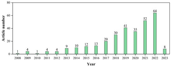
Figure 2.
The development of biohydrogen production from S. japonica during the past years based on the number of articles being published until February 2023. The article number is determined by searching the Scopus database for “Article title, Abstract, Keywords” with the keyword as “hydrogen” OR “H2” OR “hydrogen production” OR “H2 production” AND “bio” OR “biological” AND “macroalgae” OR “seaweed” AND “Saccharina japonica” OR “Laminaria japonica” OR “Phaeophyta japonica”.
2. Biohydrogen Production from S. japonica via Dark Fermentation (DF)
2.1. Principle of DF
The generation of bio-H2 via DF occurs under anaerobic conditions with the primary participation of strictly anaerobic or facultative anaerobic bacteria. Due to no sunlight being required to operate, this method is commonly known as dark fermentation (DF) [47]. Compared with photo fermentation, DF has several benefits, such as (i) being independent of weather conditions, (ii) being more suitable with complex substrates, and (iii) providing a higher H2 production rate [48]. Furthermore, almost no energy requirement is a great advantage of DF over other bio-H2 production methods [12].
DF is part of the entire process of anaerobic digestion (AD) [49] to generate biogas, composed primarily of H2 and CO2, and effluent, including end products such as volatile fatty acids (VFAs), ethanol, butanol, etc. [50]. Figure 3 illustrates the DF process consisting of two main stages: hydrolysis and acidogenesis. DF begins with the hydrolysis stage when hydrolytic fermentative bacteria break down the initial complex organic matter into simpler monomers available for microorganism consumption, such as amino acids, monosaccharides, and fatty acids. The acidogenesis stage is a process in which intracellular reduced co-factors such as acidogenic bacteria continue to convert the hydrolysis stage products into H2, CO2, VFAs, ethanol, and other products.
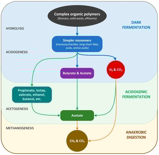
Figure 3.
The link between DF process and AD process.
The theoretical H2 yield of DF is estimated when DF is fed with glucose, as depicted in Equations (1) and (2) [51]. Based on Equation (1), the highest theoretical H2 yield of DF is 4 mol per 1 mol of glucose if acetic acid (HAc) is the end product [51].
In another case, when butyric acid (HBu) is the end product, the maximum H2 yield reduces to 2 mol per 1 mol glucose [51], according to Equation (2).
However, both reactions have negative Gibbs free energy or are thermodynamically favorable, implying that simultaneous HAc and HBu production can often be observed. However, in the practice of DF, many other by-products are also present in the DF effluent.
2.2. Performance of DF for H2 Production from S. japonica
Table 3 summarizes the bio-H2 production obtained from S. japonica via DF. Overall, if calculated based on theoretical data, the H2 recovery from S. japonica via DF up to now is only 2–28%. This low H2 yield may be due to the thermodynamic limit of DF, and the change in H2 yield depends on the various operating parameters of DF.
Table 3.
Summarization of biohydrogen production from S. japonica via DF.
2.3. Operational Parameter of DF
2.3.1. DF Microorganism
Numerous types of fermentative bacteria can generate H2 via DF, called the H2-producing bacteria or H2-synthesizing bacteria [9,48,59]. The common H2-producing bacteria include strict anaerobes (e.g., Clostridium sp. [60,61], Thermoanaerobacterium sp. [62], Ethanoligenens sp. [63], etc.) facultative anaerobes (e.g., Bacillus sp. [64], Enterobacter sp. [63], Klebsiella sp. [65], etc.), and even aerobes (e.g., Alcaligenes sp. [59]). Clostridium sp. and Enterobacter sp. are the most commonly studied [59]. Along with pure culture, mixed and co-culture has also been widely applied in research and applications of DF [47]. Generally, the use of mixed cultures is considered the optimal option when applying DF on a large scale [47] due to its many advantages. As detailed, (i) the mixed cultures are abundant in nature that can be collected from a diversity of sources, including acclimated sludge, digested sludge, sewage sludge, compost, animal manure, soil, etc. [59]; (ii) process control and operation are more convenient when there is no need of medium sterilization, thus reducing operating costs; (iii) in addition, they are less affected by in substrate type and composition; thus, they allow for a wider selection of materials [59].
2.3.2. Inoculum Enrichment and Inhibit Methanogens Methods
As mentioned above, utilizing mixed culture of H2-producing bacteria generally offers more technical and economic benefits than pure culture. However, these mixed cultures often contain many H2-consuming bacteria (or H2 consumers), such as homoacetogens and methanogens, which reduce the bio-H2 production in DF. Therefore, enriching these mixtures by inhibiting H2 consumers is essential before using them as seed culture or inoculum to start up DF. The inoculum enrichment is achieved through physical or chemical methods, or a combination of the two [66]. Physical methods include a variety of sub-methods such as using heat (with various conditions temperature from 60 °C to 121 °C for 15 min to 12 h [67,68]), ultraviolet irradiation [69], freeze and thaw [70], ultrasonication [69], aeration [71], etc. Meanwhile, chemical methods contain pH pretreatment (at pH 3 and pH 10 [67,72]), and chemical activation and inhibition (such as 2-bromoethanesulfonate, acetylene, chloroform [67], iodoform [34,41], β-cyclodextrin [41], etc.).
2.3.3. Substrate Pretreatment
Substrate pretreatment is necessary when complex substrates, including macroalgae, are used in DF. When using macroalgae as a substrate, the complex composition, particularly in the cell wall of macroalgae, contains cellulose, protein, sulfated fucans, and alginates, which hinders the activity of microorganisms in DF. Therefore, many studies have targeted identifying the optimal substrate pretreatment conditions for improving the solubilization of macroalgae, thereby increasing the performance of DF [24]. There are many pretreatment methods that have been applied for DF fed with S. japonica, including (i) thermal pretreatment (60 and 120 °C for 30 min [24]; 170 °C and 20 min [38]); (ii) acidification pretreatment [24,73]; (iii) alkaline pretreatment [24]; (iv) using electric field [54]; or a combination of them. To date, the combination of acid (4.8% HCl) and thermal methods (93 °C for 23 min) for S. japonica pretreatment has been reported to be optimal when obtaining a maximum of 159.6 mL of H2 from 1 g-TS of S. japonica [42].
2.3.4. Substrate Concentration
In the DF process, a small feedstock concentration is essential for activating germination and preventing the regeneration of spore-forming bacteria. However, low substrate concentrations can cause long lag times and slow H2 production rates due to substrate limitations that may harm DF productivity [74]. Meanwhile, it was evident that when DF is operated at high concentrations, it is economically beneficial to save the required energy during fermentation (mainly heating costs) [48]. However, high substrate concentrations can also interfere with H2 production in DF, as the activity of H2-producing bacteria may be inhibited by high concentrations of generated VFAs [74,75]. In addition, when pH is not controlled during DF, high substrate concentrations associated with large amounts of VFA are produced, resulting in a pH drop in the DF broth and inhibiting H2-producing bacteria [76] (more detailed in the next section). Therefore, optimizing substrate concentration is critical to enhancing H2 production in DF.
Most studies of DF fed with S. japonica usually focus on concentrations from 1 to 110 g-TS/L. However, the literature results reported that the optimal concentration was around 30 g-TS/L of S. japonica (equivalent to approximately 20 g-COD/L) [24,34,39,40,53]. In this case, substrate concentrations higher than 50 g-TS/L usually reduce DF performance due to substrate inhibition and significant mixing problems caused by the gelatinization of S. japonica in DF broth [34,53].
2.3.5. pH
pH is considered one of the most sensitive and critical operating parameters that affect DF performance, as it can alter the metabolic pathway of DF [48]. P. Fang and H. Liu [77] reported that increasing the pH to 4.0–7.0 may decrease the HBu production and increase the HAc generation, whereas both productions became balanced at near neutral pH. Moreover, after summarizing the reports about H2 production from seed sludge by DF, Y. Wong et al. [66] concluded that the highest H2 production was achieved in the pH range of 6.0–6.5. Generally, H2 production is often low in acidic environments (pH < 4) due to the generation of acidic and alcoholic metabolites, which can invade the bacterial cell membrane and prevent regular metabolic activities. Conversely, alkaline environments (pH > 7) also reduce H2 generation due to the formation and accumulation of propionic acid (HPr), which consumes reducing powers that are likely to be used to synthesize H2 [48]. Therefore, to avoid these inhibitions and improve H2 production, it is important to uphold the pH within the optimal range. Several studies have investigated the pH influence on the DF process using S. japonica as a substrate. The reported results showed that the optimal condition was an initial pH of 7.0–7.5 [53] and a cultivation pH of 5.5–6.0 [24,34,39].
2.3.6. Temperature
As with pH, temperature plays an important role in DF, changing the metabolic pathways so that different microorganisms become dominant with temperature changes [48]. Studies have reported that DF can be performed at a wide range of temperatures from 25 °C to above 80 °C [48]. The different temperature ranges can be divided into four groups including (i) mesophilic (25–40 °C), (ii) thermophilic (40–65 °C), (iii) extreme thermophilic (65–80 °C), and (iv) hyperthermophilic (>80 °C). Despite the vast range of operating temperatures, most studies have focused on operating DF at the mesophilic condition to achieve high DF performance without concerns about temperature inhibition. In addition, it also contributes to making DF more economical by saving energy used to maintain the temperature of the DF reactor. Generally, the increase in operating temperature within an appropriate range can significantly improve the H2 production of DF [78] because high temperature can enhance both the biological and physicochemical degradation of the substrate [48], which is one of the key steps to increasing the DF performance fed with macroalgae [79]. Unfortunately, this also implies that low temperatures are detrimental to substrate degradation, which may decrease DF performance. Moreover, high operating temperatures (>60 °C) can inhibit the activity of homoacetogens and methanogens [79]. However, too high temperatures can inhibit H2-producing bacteria by disabling vital enzymes for the growth of bacterial cells and denaturing the cell’s proteins, excluding hyperthermophilic H2-producing bacteria, such as Pyrococcus furiosus and Thermotoga maritima.
Thus far, few studies have reported on the effect of temperature on DF fed with S. japonica. J. Park et al.’s [30] study can be considered the first to investigate the ability to produce H2 from S. japonica via DF. In this study, J. Park et al. reported that 35 °C is the optimal temperature compared to other temperatures of 25, 45, and 55 °C. Probably relying on that, most DF experiments in other studies about S. japonica were conducted at temperatures between 30 and 37 °C.
3. Biohydrogen Production from S. japonica via Microbial Electrolysis Cell (MEC)
An MEC is a bio-electrochemical system for bio-H2 production with a maximum theoretical H2 yield of 12 mol per mol of glucose [10]. With a high H2 production rate, light-independent, and requiring less energy, the MEC system has now been considered a potential method for bio-H2 generation and has gained much research interest [80,81].
3.1. Principle of MEC
The MEC system is similar to DF when both occur in anaerobic conditions but differs in that MEC operation requires the combination of microorganisms and an external power source. In an MEC, microorganisms can oxidize organic compounds to form electrons, protons, and CO2 at the anode. The electron then transfers from exoelectrogen to the anode surface by some or all of three pathways, including (i) direct electron transfer, (ii) through electron shuttle, and (iii) through conductive biofilm and conductive pili [82]. While the protons travel through the membrane or simply diffuse through the electrolyte to the cathode, the electrons continue to pass through to the cathode under the applied voltage. At the surface of the cathode, the electrons reduce the protons to form H2. The reaction at the anode is expressed according to Equation (3) when taking acetate as an example.
Under standard conditions (pH = 7.0, T = 298.15 K, [CH3COO−] = 0.0169 mol/L (1 g/L) and [HCO3−] = 0.005 mol/L), the theoretical anode potential (Ean) for acetate oxidation can be determined by the Nernst equation (Equation (4)).
At the cathode, the release of H2 at the cathode is achieved by HER reaction followed by Equation (5).
The theoretical cathode potential (Ecat) under standard conditions (pH = 7.0, T = 298.15 K, and pH = 1 atm) is calculated by following Equation (6).
The equilibrium voltage (Eeq) for acetate under standard conditions can be calculated as Equation (7).
The negative Eeq implies that the conversion of acetate into H2 in MECs is not spontaneous, and for the reaction to become favorable and produce H2, an external voltage (>0.114 V) must be applied. In practice, the applied voltage (Eap) is generally higher due to the loss of energy and voltage in the MEC system. Previous MEC studies have reported that Eap > 0.2 V is required to achieve quantifiable H2 generation in MECs. However, this voltage is much lower than the voltages required for water electrolysis (typically 1.23–2.0 V) [83]. Indeed, it has been reported that the energy requirement for MECs is only about 0.6 kWh/m3 (0.2 mol H2 energy/mol-H2 produced), whereas, in water electrolysis, 4.5–5 kWh/m3 is required (1.5–1.7 mol H2 energy/mol-H2 produced) [8].
MECs can produce H2 from a large amount of simple and complex organic substances, including fermentable substrates (such as glucose, saccharose, cellulose, etc.), non-fermentable substrates (VFAs, ethanol, glycerol, etc.), and various kinds of wastewater. Because of the possible oxidation of non-fermentable substances, mainly DF end products, MECs can completely consume organic substrate and obtain a theoretical maximum H2 yield of 12 mol/mol of glucose [10], much higher than DF. The literature results showed that the exoelectrogens in MECs prefer simple substrates to complex substrates such as polymeric materials or wastewater. For instance, H2 can be generated in more quantity and faster from VFAs, alcohols, or glucose; in particular, HAc showed the highest conversion performance, with the H2 production rates up to 6.3–50 L/L/d [83,84]. Meanwhile, the poor performance of MECs was found in complex compounds, such as proteins, where the H2 production rate was only 0.05 L/L/d [85]. Accordingly, when S. japonica was used as the substrate for MECs, the H2 yield and rate were 203.2 ± 6.2 mL/g-TS and 0.34 ± 0.02 L/L/d, respectively, significantly lower than those of MECs fed with VFAs such as acetate, butyrate, and propionate [44]. The reason is that S. japonica contains various complex structural polysaccharides that are not readily hydrolyzed by conventional microorganisms [44].
3.2. Operational Parameter of MECs
3.2.1. Microorganisms in MECs
As mentioned above, microorganisms in MECs can donate electrons to anode electrodes through the oxidation of organic substrates. They are often called exoelectrogens, anode-respiring bacteria, electricigens, or electrochemically active bacteria [10,86]. In MECs, exoelectrogens oxidize the organic compounds to form important products, including protons and free electrons. In other words, exoelectrogens play a crucial role in MECs [83].
Exoelectrogens so far belong to various genetic groups, mainly belonging to Proteobacteria phylum, including α-Proteobacteria (Acidiphilium, Ochrobactrum, Rhodopseudomonas, etc.), β-Proteobacteria (Rhodoferax), γ-Proteobacteria (Aeromonas, Citrobacter, Enterobacter, Klebsiella, Shewanella, etc.), δ-Proteobacteria (Desulfobulbus, Geopsychrobacter, Geobacter, etc.), and ε-Proteobacteria (Arcobacter) [83,87,88,89]. In addition, there are a few that belong to Firmicutes phylum (Clostridium and Thermincola) and Acidobacteria phylum (Propionibacterium, Geothrix) [83]. The dominance of certain exoelectrogens species in MECs depends on the operating conditions, especially the style of substrate fed into MECs.
As with DF, the seed culture or inoculum enrichment is a critical stage. Four widely used methods exist for inoculating MECs [71], including (i) operating MFCs until reaching stable power production and then shifting such anodes to MECs. This process guarantees the growth of exoelectrogenic on the surface of anodes and offers a fast start-up for MEC operation [90,91,92]; (ii) using the effluent from running MFCs/MECs or scratching biofilms from these anodes [93,94]; (iii) directly using the bacteria source from wastewater or anaerobic sludge as seeds [90,95,96,97,98,99]; and (iv) using cultured pure exoelectrogen species [91,100].
3.2.2. MEC Reactor Configurations and Designs
Thus far, there have been many different configurations of MECs and various types and materials of anode, cathode, and membrane to improve the efficiency and reduce the overall costs of MECs. Pictures of these MECs can easily be found in the previous review papers of A. Kadier et al. [83,101]. Although different in structure and design, they all share the same operating principles. Generally, the change in configuration and design of the MEC reactor will result in a change in the internal resistance of the MEC and a parameter that directly affects the generated current density and H2 production yield.
Basically, MEC reactor configurations and designs are classified into two common styles based on membrane usage, including (i) two-chamber MECs and (ii) single-chamber MECs. The two-chamber MEC was the most commonly used design during the early MEC study. This design consists of two compartments, anode and cathode chambers, separated by an ion exchange membrane (Figure 4a). The use of a membrane in two-chamber MECs faces some disadvantages, such as (i) the formation of a pH gradient that can cause a decrease in the performance of MECs. It was reported that each unit change in pH could result in a potential loss of 0.06 V [83]. (ii) In addition, the high resistance of the membrane leads to an increase in the overall internal resistance of the MEC, resulting in a decrease in the generated current density, H2 production rate, and also H2 production yield [102]. (iii) Moreover, membranes are expensive and add a considerable cost to the MEC system. (iv) Finally, it is also complex and poses practical problems as they need to be replicated [103].
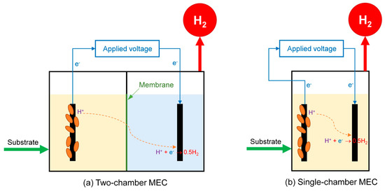
Figure 4.
The schematic diagram of (a) two-chamber MEC and (b) single-chamber MEC.
The concept of single-chamber MECs without using membranes was developed to overcome the abovementioned drawbacks of two MEC chambers. The feasibility of removing the membrane from MECs is based on some reasons, such as (i) O2 is not generated in MECs as it is in water electrolysis, and therefore, there is no requirement to keep the gas generated at the cathode separated from the anode. (ii) In addition, even though H2-consuming bacteria could consume H2 gas generated in MECs, if H2 gas generation rates were adequately high, the low solubility of the H2 gas in the liquid phase would allow high recoveries. The typical schematic diagram of a single-chamber MEC reactor is shown in Figure 4b, which includes the electrolyte sharing of the anode and cathode. Many single-chamber MECs have been developed and have displayed positive results compared to the two-chamber MECs [83]. A significant advantage of single-chamber MECs is avoiding the high resistance of the membrane, thus improving the current density and the H2 generation rate. The results of the previous studies of B. Logan et al. [92,93] can be considered a typical example. In detail, under the same anode and cathode materials conditions, 1.0 g/L of acetate, Eap of 0.6 V, the H2 production rate in single-chamber MEC reached 1.99 L/L/d [92], higher than the two-chamber MEC of 1.1 L/L/d [93]. Moreover, single-chamber MECs are easier to fabricate, voiding operational problems related to membranes, such as clogging, fouling, etc., resulting in reduced costs in the single-chamber MEC systems [83].
3.2.3. Applied Voltage
As mentioned above, the external voltage is required to form H2 in MECs. In addition to supplying the main energy for carrying out the HER reaction in the cathode, the applied voltage has also been reported to support energy for the activity of exoelectrogens at the anode. Theoretically, at low Eap, exoelectrogens acquire less energy for growth, resulting in lower biomass accumulation, slower development of the anode biofilm community, and more delayed start-up of H2 production [104]. On the other hand, at higher Eap, exoelectrogens could acquire more energy for growth if they can capture this additional energy [105]. Additionally, high Eap can improve the kinetics of substrate oxidation by supplying a high driving force for bacteria-to-electrode extracellular electron transfer [106]. However, occasionally, when Eap is very high, the bacteria can be damaged by electric shock [92]. Moreover, a higher voltage consumes more external energy, making MECs almost similar to the water electrolysis process and reducing energy efficiency [107]. Because of that, most MECs are operated at an Eap of 0.2–1.0 V, whereas more than 1.1 V is not recommended [83].
There are two ways to apply voltage for MECs, including (i) setting the anode potentials by a potentiostat (that is operated in three-electrode mode) [108] and (ii) adding voltage by using a power supply or potentiostat (that is operated in two-electrode mode) [109]. In setting the anode potentials, one of the electrode potentials in MECs can be controlled by using a reference electrode inserted into the liquid phase. The major drawback of this system is that if the potentiostat controls one electrode potential, then the potential of the other electrode will change. Therefore, if the anode potential is set, the cathode potential cannot be controlled. The amount of energy input into the MEC will thus change in response to the overpotential needed at the cathode to maintain the current generated at the anode [109].
In the case of adding voltage, the potential change in the two electrodes occurs simultaneously. In MECs, the anode potential usually becomes more positive with higher Eap due to many factors, mainly exoelectrogen activity or substrate concentration changes [108]. However, simultaneously, as the anode potential becomes more positive, the cathode potential also becomes more positive. Although the electrode potentials can change, the major benefit of the voltage promotion is that the amount of energy added to the MEC system is well controlled [110,111].
3.2.4. Electrolyte
The characteristics of electrolytes, such as conductivity and pH, are important factors that affect the performance of MECs. The pH of the electrolyte may affect the activity of exoelectrogens at the anode and HER potential on the cathode [83]. Meanwhile, the electrolyte conductivity can influence the internal resistance of MECs. In MECs, almost all studies investigated the pH ranging from 5–9 [83], and with single-chamber MECs, the optimal pH value was around 6.7–7.0 [84]. Using buffers in MECs is also necessary, which helps avoid operational problems such as the limitations of proton transport inside the biofilm of exoelectrogens and provides conductivity to the electrolyte [112]. A variety of buffer solutions, such as phosphate, bicarbonate, ammonia, 2-N-morpholino ethane sulfonate, 4-(2-hydroxyethyl)-1-piperazineethanesulfonic acid, etc., have been used in previous MEC studies [113,114,115]. However, buffers may not be economical and eco-friendly [116]. Furthermore, recent studies have reported that buffers are only needed for single-chamber MECs and anolyte in two-chamber MECs where necessary to uphold a neutral pH condition for the activity of exoelectrogens. In contrast, the conductivity of the catholyte in two-chamber MECs is more important than using any specific buffer [111]. Therefore, some solutions such as salt solution (NaCl), acidified solution (HCl, H2SO4), or even water were used as the catholyte in MECs [116,117,118,119]. However, until now, there has been no study to conclude the economic efficiency of two-chamber MECs without buffers compared to single-chamber MECs without using membranes.
3.2.5. Temperature
The temperature may be anticipated to (i) affect the activity and selection of exoelectrogens in MECs; (ii) influence the mass transport of reactants and products to and from the electrodes, (iii) affect the kinetics of the reaction, and (iv) have an impact on the electrode potentials based on the Nernst equation [120]. The high temperatures often offer many advantages, such as (i) they can enhance both the biological and physicochemical degradation of the substrate that enhances the activity of exoelectrogens [48]. (ii) In addition, the high temperatures are associated with an improvement in the rate of buffer diffusion leading to a boost in the rate of proton transport out of the anode biofilm, thus avoiding acidification in the anode [121]. (iii) A high temperature can reduce the gas (H2, CO2) absorption (the solubility) in the electrolyte that can be consumed by the activity of H2-consuming bacteria [121]. (iv) Furthermore, according to the Nernst equation, the electrode potentials will decrease with increasing temperature [122]. However, Y. Ahn et al. showed that a higher temperature of over 40 °C could inhibit the activity of exoelectrogen on the anode [123]. The results from the literature suggest the optimal temperature for MECs is around 30 °C [83,124,125].
3.2.6. Electrode Size and Distance
Several studies have reported that the H2 production rate of MECs increases considerably as the electrode distance decreases and the electrode surface area ratio to the electrolyte volume of MECs increases [91,126,127,128,129]. Reducing the electrode spacing is closely related to the reduction in the internal resistance of the MECs, increasing the rate of H2 production [126,130]. S. Cheng and B. E. Logan [130] reported that when the distance of electrodes decreased from 3.5 cm to 2 cm, the H2 production rated linearly increased from 3.9 to 13.5 L/L/d (at Eap of 0.8 V). However, the H2 production rate decreased to 11.0 L/L/d when that distance was reduced to 1 cm. The reason is that the excessive reduction in distance between the electrodes leads to the limitation of the anode surface for exoelectrogens. This insufficient surface led to the reduction in MEC performance. In other words, maintaining a high anode surface area for exoelectrogens in MECs is important to ensure high efficiency for MECs [130].
The above hypothesis has been elucidated in the study of L. Verea et al. [131], which investigated the effect of the surface area of an anode, which was designated as the anode surface area/electrolyte volume ratio, on the MEC performance. L. Verea et al. reported that the highest H2 production rate was obtained at the highest surface area of the anode. However, it should be noted that increasing the anode surface area will decrease the actual working volume, which may reduce the productivity of MECs.
3.2.7. Substrate Concentration
To date, not much research has been reported on the influence of substrate concentration on the performance of MECs. Instead, the MEC is usually widely operated at low concentrations of 1–5 g/L to focus on the flexibility in the utilization of the substrates of MECs. Similar to H2-producing bacteria in DF, it can be predicted that high substrate concentrations can inhibit and exert stress on exoelectrogens [132,133,134]. A. Escapa et al. [135], after investigating the H2 production from domestic wastewater via a continuous flow MEC, concluded the H2 production rate in their MEC was saturated at the organic loading rate above 2.0 g-COD/L/d. However, it should be noted that the saturation of MECs is also related to other parameters, such as the surface area of the electrodes and the value of the applied voltage to the MECs. In other words, the influence of substrate concentration or saturation in an MEC needs to be further researched in the future.
3.2.8. Inhibition of H2-Consuming Bacteria in MECs
Before discussing this section, it is necessary to mention the paths of H2 and the formation of CH4 in MECs. There are three possible routes after H2 is formed in the cathode, including (i) it escapes from the liquid phase and is taken out from the MEC reactor, which is the desired path; (ii) it dissolves in the liquid phase and is consumed by homoacetogens to regenerate acetate. This path, known as the H2-acetate loop or H2-recycling, leads to a prolongation of the operation cycles and, therefore, more input energy requirements and lower H2 recoveries [136,137,138,139]; (iii) it dissolves in the liquid phase and is consumed by hydrogenotrophic methanogens to form CH4 [132,140]. This path directly reduces the H2 production yield of MEC. Moreover, CH4 is generated through the activity of the direct electromethanogenes and the acetoclastic methanogens, which indirectly reduces H2 production yield through the competition of substrates (proton and acetate) that are used in H2 production [140,141,142,143]. Obviously, it is essential to suppress the activity of methanogens and homoacetogens to enhance the H2 yield and energy efficiency of MECs. Thus far, many methods have been developed to prevent the activity of H2-consuming bacteria in the MECs, such as (i) exposing the electrodes and reactor to air [91,92,144,145]; (ii) temperature shock [146]; (iii) lowering pH [91]; (iv) lowering temperature (<10 °C) [143]; (v) limiting bicarbonate [147]; (vi) using ultraviolet irradiation [148]; (vii) using chemical inhibitors such as 2-bromoethanesulfonate [144], chloroform [149], etc. In addition, some methods such as (viii) reducing hydraulic retention time or operating cycles [150] and (ix) using higher Eap (>0.6 V) [150,151] to accelerate the H2 production rate can minimize the dissolution of H2 into the liquid phase.
4. Biohydrogen Production from S. japonica via the Integration of DF and MEC
As mentioned above, H2 production via DF is limited at 4 mol H2/mol glucose because two-thirds of the hydrogen element is trapped in the formation of by-products, mainly VFAs [16,17,152]. Meanwhile, H2 can be fully recovered via MECs. However, the exoelectrogens in MECs prefer simple substrates to polymeric materials or complex wastes [153,154]. Thus, it can be argued that DF and MECs can complement each other when the advantage of the other overcomes the weakness of one process. In other words, combining DF and MECs can increase the overall H2 yield and substrate conversion efficiency [83,149]. Figure 5 shows the principle of the combination of DF and MECs in the two-stage process (DF-MEC). Accordingly, fermentative bacteria break down resistant polymers and complex substrates into short-chain metabolites in the first stage of DF-MEC (i.e., DF). These simple substances are then further converted to H2 in the second stage (i.e., MEC) [155,156,157].
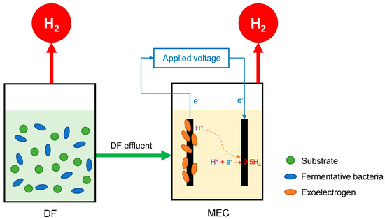
Figure 5.
Diagram of the two-stage DF and MEC process (DF-MEC).
Many studies have reported the potential of the DF-MEC with higher performance when compared to DF alone or MECs alone [133,158,159,160,161,162,163,164,165,166,167,168,169,170]. The maximum overall H2 yield was improved at 538%, with an average improvement of 225%. In addition, the maximum overall H2 production rate was enhanced at 400%, with an average enhancement of 148% [156,161,165]. For more detail, E. Lalaurette et al. [155] investigated DF-MEC using corn stalks that produced the overall H2 yield of 9.95 mol-H2/mol glucose compared with only 1.67 mol-H2/mol glucose by DF alone. Wang et al. [133] also reported that the H2 production from cellulose by DF-MEC achieved the highest overall H2 yield of 14.3 mmol H2/g cellulose compared to 10.1 mmol H2/g cellulose in DF alone.
A. Marone et al. [168] evaluated H2 production by DF-MEC fed with six different wastewaters (from spirits factories, fruit, paper, cheese, sugar, and fruit juice processing). As a result, the overall H2 production via DF-MEC was enhanced by up to 13 times when compared to DF alone, achieving a maximum overall H2 yield of 1608.6 ± 266.2 mL-H2/g-CODconsumed. Similarly, R. Moreno et al. [164] reported the high H2 yield of DF-MEC fed with cheese whey wastewater.
Table 4 summarizes the bio-H2 production obtained from S. japonica via MECs and their combination with DF. As a result, DF-MEC can be considered an auspicious process to maximize H2 production when using S. japonica as a substrate. However, this combination requires auxiliary processes such as solid removal, dilution, and pH adjustment of DF effluent [139,153,154] that increase operational costs. To overcome the disadvantages of DF-MEC, another concept has been developed that can enable high performance from complex organic substances in one reactor. This concept is described in Figure 6 where the activities of fermentative bacteria and exoelectrogens simultaneously take place in a reactor, namely sDFMEC. Specifically, the activity of fermentative bacteria that takes place in the bulk broth phase of sDFMEC breaks down the macroalgae into H2, VFAs, and other biomolecules, and such VFAs are concurrently converted by the exoelectrogens in the biofilm on the anode electrode with a further generation of H2 at the cathode. Accordingly, sDFMEC is anticipated to improve H2 yield and process economics. Moreover, the pH inhibition by VFAs’ formation by fermentative bacteria could be minimized because the MEC almost immediately consumes such VFAs, and the solubility of the generated CO2 could contribute to pH buffering in the broth [44,171,172]. The H2 yield from S. japonica via sDFMEC was reported to be 8.0, 2.2, and 1.1 times higher than DF alone, MEC alone, and DF-MEC, respectively [44]. A maximum H2 yield of 492.3 ± 5.1 mL/g-TS can be achieved from S. japonica when sDFMEC is operated under optimal conditions with a temperature of 36.6 °C, an initial pH of 7.44, and a substrate concentration of 1.98 g/L [171].
Table 4.
Summarization of biohydrogen production from S. japonica via MEC and its combination with DF.
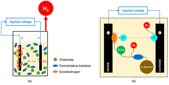
Figure 6.
(a) Diagram of the single-stage DF and MEC process (sDFMEC) and (b) scheme principle of S. japonica-fed sDFMEC.
5. Future Perspectives
Even though bio-H2 production from S. japonica showed good efficiency, mainly when applied in the bio-electrochemical systems (e.g., MEC, DF-MEC, sDFMEC), scaling up from the laboratory to pilot-scale and beyond to be applied in practice still requires much work: (i) The effect of other operating parameters on bio-electrochemical systems, such as applied voltage, types of electrolyte solution, the ratio of the surface area of electrodes and the electrolyte volume, etc., especially operation in continuous mode, should be further investigated. (ii) Some methods have been used to prevent the formation of CH4 by inhibiting the activity of methanogens, such as exposure to the electrodes in the air, using high applied voltage, etc. These are easy, inexpensive, and environmentally friendly methods; however, complete inhibition has not yet been achieved in bio-electrochemical systems, especially for long-term operations. Thus, it could be expected that it will become challenging to operate bio-electrochemical systems in continuous mode if no more effective methods of methanogens inhibition are developed. In other words, developing more effective methods of methanogens inhibition is extremely important for enhancing H2 production from S. japonica. (iii) New low-cost, stable, and high-performance electrode materials used in bio-electrochemical systems need to be further investigated to improve the economics of these processes. (iv) Modeling and economic analysis of biological H2 production from S. japonica should also be studied.
6. Conclusions
This review summarized the current status of biohydrogen production using S. japonica and provided an overview of how to improve this process’s efficiency. Dark fermentation, microbial electrolysis cells, and their combination are the most extensively studied processes for bio-H2 production from S. japonica. According to proper operating conditions, it can be concluded that using appropriate pretreatment methods, the effective inhibition of methane production, and the integration of DF into the MEC can boost the bio-H2 yield from S. japonica. In sum, S. japonica-derived biohydrogen production provides a reliable and environmentally friendly alternative energy source. However, its economic effectiveness needs to be further studied for clarification.
Funding
This study was supported by the Basic Science Research Capacity Enhancement Project through the Korea Basic Science Institute (National Research Facilities and Equipment Center) grant funded by the Ministry of Education (Grant No. 2019R1A6C1010016).
Institutional Review Board Statement
Not applicable.
Informed Consent Statement
Not applicable.
Data Availability Statement
No data were used for the research described in the article.
Conflicts of Interest
The authors declare that they have no known competing financial interests or personal relationships that could have appeared to influence the work reported in this paper.
References
- Sun, Z.-F.; Zhao, L.; Wu, K.-K.; Wang, Z.-H.; Wu, J.-T.; Chen, C.; Yang, S.-S.; Wang, A.-J.; Ren, N.-Q. Overview of recent progress in exogenous hydrogen supply biogas upgrading and future perspective. Sci. Total. Environ. 2022, 848, 157824. [Google Scholar] [CrossRef] [PubMed]
- Li, H.; Cao, X.; Liu, Y.; Shao, Y.; Nan, Z.; Teng, L.; Peng, W.; Bian, J. Safety of hydrogen storage and transportation: An overview on mechanisms, techniques, and challenges. Energy Rep. 2022, 8, 6258–6269. [Google Scholar] [CrossRef]
- Khan, M.; Nizami, A.; Rehan, M.; Ouda, O.; Sultana, S.; Ismail, I.; Shahzad, K. Microbial electrolysis cells for hydrogen production and urban wastewater treatment: A case study of Saudi Arabia. Appl. Energy 2016, 185, 410–420. [Google Scholar] [CrossRef]
- Tran, N.; Ta, Q.T.H.; Nguyen, P.K.T. Transformation of carbon dioxide, a greenhouse gas, into useful components and reducing global warming: A comprehensive review. Int. J. Energy Res. 2022, 46, 17926–17951. [Google Scholar] [CrossRef]
- Das, D. Hydrogen production by biological processes: A survey of literature. Int. J. Hydrog. Energy 2001, 26, 13–28. [Google Scholar] [CrossRef]
- Das, D. Advances in biohydrogen production processes: An approach towards commercialization. Int. J. Hydrog. Energy 2009, 34, 7349–7357. [Google Scholar] [CrossRef]
- Weber, A.Z.; Lipman, T.E. Fuel Cells and Hydrogen Production: Introduction. In Fuel Cells and Hydrogen Production; Meyers, R.A., Ed.; Springer: New York, NY, USA, 2018; pp. 1–8. [Google Scholar] [CrossRef]
- Karthikeyan, R.; Cheng, K.Y.; Selvam, A.; Bose, A.; Wong, J.W. Bioelectrohydrogenesis and inhibition of methanogenic activity in microbial electrolysis cells—A review. Biotechnol. Adv. 2017, 35, 758–771. [Google Scholar] [CrossRef]
- Ghimire, A.; Frunzo, L.; Pirozzi, F.; Trably, E.; Escudie, R.; Lens, P.N.; Esposito, G. A review on dark fermentative biohydrogen production from organic biomass: Process parameters and use of by-products. Appl. Energy 2015, 144, 73–95. [Google Scholar] [CrossRef]
- Parkhey, P.; Gupta, P. Improvisations in structural features of microbial electrolytic cell and process parameters of electrohydrogenesis for efficient biohydrogen production: A review. Renew. Sustain. Energy Rev. 2017, 69, 1085–1099. [Google Scholar] [CrossRef]
- Nikolaidis, P.; Poullikkas, A. A comparative overview of hydrogen production processes. Renew. Sustain. Energy Rev. 2017, 67, 597–611. [Google Scholar] [CrossRef]
- Rezania, S.; Din, M.F.M.; Taib, S.M.; Sohaili, J.; Chelliapan, S.; Kamyab, H.; Saha, B.B. Review on fermentative biohydrogen production from water hyacinth, wheat straw and rice straw with focus on recent perspectives. Int. J. Hydrog. Energy 2017, 42, 20955–20969. [Google Scholar] [CrossRef]
- Chang, H.N.; Kim, N.-J.; Kang, J.; Jeong, C.M. Biomass-derived volatile fatty acid platform for fuels and chemicals. Biotechnol. Bioprocess Eng. 2010, 15, 1–10. [Google Scholar] [CrossRef]
- Wei, N.; Quarterman, J.; Jin, Y.-S. Marine macroalgae: An untapped resource for producing fuels and chemicals. Trends Biotechnol. 2013, 31, 70–77. [Google Scholar] [CrossRef] [PubMed]
- Jones, C.S.; Mayfield, S.P. Algae biofuels: Versatility for the future of bioenergy. Curr. Opin. Biotechnol. 2012, 23, 346–351. [Google Scholar] [CrossRef] [PubMed]
- Sambusiti, C.; Bellucci, M.; Zabaniotou, A.; Beneduce, L.; Monlau, F. Algae as promising feedstocks for fermentative biohydrogen production according to a biorefinery approach: A comprehensive review. Renew. Sustain. Energy Rev. 2015, 44, 20–36. [Google Scholar] [CrossRef]
- Sudhakar, K.; Mamat, R.; Samykano, M.; Azmi, W.; Ishak, W.; Yusaf, T. An overview of marine macroalgae as bioresource. Renew. Sustain. Energy Rev. 2018, 91, 165–179. [Google Scholar] [CrossRef]
- del Río, P.G.; Gomes-Dias, J.S.; Rocha, C.M.; Romaní, A.; Garrote, G.; Domingues, L. Recent trends on seaweed fractionation for liquid biofuels production. Bioresour. Technol. 2019, 299, 122613. [Google Scholar] [CrossRef]
- John, R.P.; Anisha, G.; Nampoothiri, K.M.; Pandey, A. Micro and macroalgal biomass: A renewable source for bioethanol. Bioresour. Technol. 2011, 102, 186–193. [Google Scholar] [CrossRef]
- Wargacki, A.J.; Leonard, E.; Win, M.N.; Regitsky, D.D.; Santos, C.N.S.; Kim, P.B.; Cooper, S.R.; Raisner, R.M.; Herman, A.; Sivitz, A.B.; et al. An Engineered Microbial Platform for Direct Biofuel Production from Brown Macroalgae. Science 2012, 335, 308–313. [Google Scholar] [CrossRef]
- Gao, K.; McKinley, K.R. Use of macroalgae for marine biomass production and CO2 remediation: A review. J. Appl. Phycol. 1994, 6, 45–60. [Google Scholar] [CrossRef]
- Marinho, G.S.; Holdt, S.L.; Jacobsen, C.; Angelidaki, I. Lipids and Composition of Fatty Acids of Saccharina latissima Cultivated Year-Round in Integrated Multi-Trophic Aquaculture. Mar. Drugs 2015, 13, 4357–4374. [Google Scholar] [CrossRef] [PubMed]
- Sharma, S.; Neves, L.; Funderud, J.; Mydland, L.T.; Øverland, M.; Horn, S.J. Seasonal and depth variations in the chemical composition of cultivated Saccharina latissima. Algal Res. 2018, 32, 107–112. [Google Scholar] [CrossRef]
- Park, J.-I.; Lee, J.; Sim, S.J.; Lee, J.-H. Production of hydrogen from marine macro-algae biomass using anaerobic sewage sludge microflora. Biotechnol. Bioprocess Eng. 2009, 14, 307–315. [Google Scholar] [CrossRef]
- Lee, J.-H.; Lee, D.-G.; Park, J.-I.; Kim, J.-Y. Bio-hydrogen production from a marine brown algae and its bacterial diversity. Korean J. Chem. Eng. 2010, 27, 187–192. [Google Scholar] [CrossRef]
- Adams, J.M.; Gallagher, J.A.; Donnison, I.S. Fermentation study on Saccharina latissima for bioethanol production considering variable pre-treatments. J. Appl. Phycol. 2008, 21, 569–574. [Google Scholar] [CrossRef]
- Park, J.-H.; Yoon, J.-J.; Park, H.-D.; Kim, Y.J.; Lim, D.J.; Kim, S.-H. Feasibility of biohydrogen production from Gelidium amansii. Int. J. Hydrog. Energy 2011, 36, 13997–14003. [Google Scholar] [CrossRef]
- Malihan, L.B.; Nisola, G.M.; Mittal, N.; Gil Seo, J.; Chung, W.-J. Blended ionic liquid systems for macroalgae pretreatment. Renew. Energy 2014, 66, 596–604. [Google Scholar] [CrossRef]
- Jeong, T.S.; Kim, Y.S.; Oh, K.K. Two-stage acid saccharification of fractionated Gelidium amansii minimizing the sugar decomposition. Bioresour. Technol. 2011, 102, 10529–10534. [Google Scholar] [CrossRef]
- Robin, A.; Chavel, P.; Chemodanov, A.; Israel, A.; Golberg, A. Diversity of monosaccharides in marine macroalgae from the Eastern Mediterranean Sea. Algal Res. 2017, 28, 118–127. [Google Scholar] [CrossRef]
- Pena, A.; Mawhinney, T.; Ricque-Marie, D.; Cruz-Suárez, L.E. Chemical composition of cultivated seaweed Ulva clathrata (Roth) C. Agardh. Food Chem. 2011, 129, 491–498. [Google Scholar] [CrossRef]
- Mhatre, A.; Navale, M.; Trivedi, N.; Pandit, R.; Lali, A.M. Pilot scale flat panel photobioreactor system for mass production of Ulva lactuca (Chlorophyta). Bioresour. Technol. 2018, 249, 582–591. [Google Scholar] [CrossRef] [PubMed]
- Song, M.; Pham, H.D.; Seon, J.; Woo, H.C. Marine brown algae: A conundrum answer for sustainable biofuels production. Renew. Sustain. Energy Rev. 2015, 50, 782–792. [Google Scholar] [CrossRef]
- Pham, T.N.; Nam, W.J.; Jeon, Y.J.; Yoon, H.H. Volatile fatty acids production from marine macroalgae by anaerobic fermentation. Bioresour. Technol. 2012, 124, 500–503. [Google Scholar] [CrossRef] [PubMed]
- Nie, J.; Fu, X.; Wang, L.; Xu, J.; Gao, X. A systematic review of fermented Saccharina japonica: Fermentation conditions, metabolites, potential health benefits and mechanisms. Trends Food Sci. Technol. 2022, 123, 15–27. [Google Scholar] [CrossRef]
- Lee, I.-S.; Ko, S.-J.; Na Lee, Y.; Lee, G.; Rahman, H.; Kim, B. The Effect of Laminaria japonica on Metabolic Syndrome: A Systematic Review of Its Efficacy and Mechanism of Action. Nutrients 2022, 14, 3046. [Google Scholar] [CrossRef]
- Luan, F.; Zou, J.; Rao, Z.; Ji, Y.; Lei, Z.; Peng, L.; Yang, Y.; He, X.; Zeng, N. Polysaccharides from Laminaria japonica: An insight into the current research on structural features and biological properties. Food Funct. 2021, 12, 4254–4283. [Google Scholar] [CrossRef]
- Jung, K.-W.; Kim, D.-H.; Shin, H.-S. Fermentative hydrogen production from Laminaria japonica and optimization of thermal pretreatment conditions. Bioresour. Technol. 2011, 102, 2745–2750. [Google Scholar] [CrossRef]
- Shi, X.; Jung, K.-W.; Kim, D.-H.; Ahn, Y.-T.; Shin, H.-S. Direct fermentation of Laminaria japonica for biohydrogen production by anaerobic mixed cultures. Int. J. Hydrog. Energy 2011, 36, 5857–5864. [Google Scholar] [CrossRef]
- Liu, H.; Wang, G. Fermentative hydrogen production from macro-algae Laminaria japonica using anaerobic mixed bacteria. Int. J. Hydrog. Energy 2014, 39, 9012–9017. [Google Scholar] [CrossRef]
- Jung, K.; Kim, W.; Park, G.W.; Seo, C.; Chang, H.N.; Kim, Y.-C. Optimization of volatile fatty acids and hydrogen production from Saccharina japonica: Acidogenesis and molecular analysis of the resulting microbial communities. Appl. Microbiol. Biotechnol. 2015, 99, 3327–3337. [Google Scholar] [CrossRef]
- Jung, K.-W.; Kim, D.-H.; Kim, H.-W.; Shin, H.-S. Optimization of combined (acid + thermal) pretreatment for fermentative hydrogen production from Laminaria japonica using response surface methodology (RSM). Int. J. Hydrog. Energy 2011, 36, 9626–9631. [Google Scholar] [CrossRef]
- Kim, S.-S.; Ly, H.V.; Choi, G.-H.; Kim, J.; Woo, H.C. Pyrolysis characteristics and kinetics of the alga Saccharina japonica. Bioresour. Technol. 2012, 123, 445–451. [Google Scholar] [CrossRef] [PubMed]
- Nguyen, P.K.T.; Das, G.; Kim, J.; Yoon, H.H. Hydrogen production from macroalgae by simultaneous dark fermentation and microbial electrolysis cell. Bioresour. Technol. 2020, 315, 123795. [Google Scholar] [CrossRef] [PubMed]
- Gebreslassie, T.R.; Nguyen, P.K.T.; Yoon, H.H.; Kim, J. Co-production of hydrogen and electricity from macroalgae by simultaneous dark fermentation and microbial fuel cell. Bioresour. Technol. 2021, 336, 125269. [Google Scholar] [CrossRef]
- Kidanu, W.G.; Trang, P.T.; Yoon, H.H. Hydrogen and volatile fatty acids production from marine macroalgae by anaerobic fermentation. Biotechnol. Bioprocess Eng. 2017, 22, 612–619. [Google Scholar] [CrossRef]
- Łukajtis, R.; Hołowacz, I.; Kucharska, K.; Glinka, M.; Rybarczyk, P.; Przyjazny, A.; Kamiński, M. Hydrogen production from biomass using dark fermentation. Renew. Sustain. Energy Rev. 2018, 91, 665–694. [Google Scholar] [CrossRef]
- Elbeshbishy, E.; Dhar, B.R.; Nakhla, G.; Lee, H.-S. A critical review on inhibition of dark biohydrogen fermentation. Renew. Sustain. Energy Rev. 2017, 79, 656–668. [Google Scholar] [CrossRef]
- Turon, V.; Trably, E.; Fouilland, E.; Steyer, J.-P. Potentialities of dark fermentation effluents as substrates for microalgae growth: A review. Process Biochem. 2016, 51, 1843–1854. [Google Scholar] [CrossRef]
- Bundhoo, Z.M. Coupling dark fermentation with biochemical or bioelectrochemical systems for enhanced bio-energy production: A review. Int. J. Hydrog. Energy 2017, 42, 26667–26686. [Google Scholar] [CrossRef]
- Thauer, R.K.; Jungermann, K.; Decker, K. Energy conservation in chemotrophic anaerobic bacteria. Bacteriol. Rev. 1977, 41, 100–180. [Google Scholar] [CrossRef]
- Yin, Y.; Wang, J. Pretreatment of macroalgal Laminaria japonica by combined microwave-acid method for biohydrogen production. Bioresour. Technol. 2018, 268, 52–59. [Google Scholar] [CrossRef] [PubMed]
- Kim, B.; Jeong, J.; Kim, J.; Yoon, H.H.; Nguyen, P.K.T.; Kim, J. Mathematical modeling of dark fermentation of macroalgae for hydrogen and volatile fatty acids production. Bioresour. Technol. 2022, 354, 127193. [Google Scholar] [CrossRef] [PubMed]
- Jeong, D.-Y.; Cho, S.-K.; Shin, H.-S.; Jung, K.-W. Application of an electric field for pretreatment of a feedstock (Laminaria japonica) for dark fermentative hydrogen production. Biomass Bioenergy 2015, 72, 184–188. [Google Scholar] [CrossRef]
- Chen, Y.; Yin, Y.; Wang, J. Biohydrogen production using macroalgal biomass of Laminaria japonica pretreated by gamma irradiation as substrate. Fuel 2021, 309, 122179. [Google Scholar] [CrossRef]
- Yin, Y.; Hu, J.; Wang, J. Fermentative hydrogen production from macroalgae Laminaria japonica pretreated by microwave irradiation. Int. J. Hydrog. Energy 2019, 44, 10398–10406. [Google Scholar] [CrossRef]
- Yin, Y.; Wang, J. Hydrogen production and energy recovery from macroalgae Saccharina japonica by different pretreatment methods. Renew. Energy 2019, 141, 1–8. [Google Scholar] [CrossRef]
- Shi, X.; Kim, D.-H.; Shin, H.-S.; Jung, K.-W. Effect of temperature on continuous fermentative hydrogen production from Laminaria japonica by anaerobic mixed cultures. Bioresour. Technol. 2013, 144, 225–231. [Google Scholar] [CrossRef]
- Ntaikou, I.; Antonopoulou, G.; Lyberatos, G. Biohydrogen Production from Biomass and Wastes via Dark Fermentation: A Review. Waste Biomass Valorization 2010, 1, 21–39. [Google Scholar] [CrossRef]
- Chen, W.-M.; Tseng, Z.-J.; Lee, K.-S.; Chang, J.-S. Fermentative hydrogen production with Clostridium butyricum CGS5 isolated from anaerobic sewage sludge. Int. J. Hydrog. Energy 2005, 30, 1063–1070. [Google Scholar] [CrossRef]
- Adav, S.S.; Lee, D.-J.; Wang, A.; Ren, N. Functional consortium for hydrogen production from cellobiose: Concentration-to-extinction approach. Bioresour. Technol. 2009, 100, 2546–2550. [Google Scholar] [CrossRef]
- Thong, S.; Prasertsan, P.; Birkeland, N.-K. Evaluation of methods for preparing hydrogen-producing seed inocula under thermophilic condition by process performance and microbial community analysis. Bioresour. Technol. 2009, 100, 909–918. [Google Scholar] [CrossRef] [PubMed]
- Ren, N.-Q.; Guo, W.-Q.; Wang, X.-J.; Xiang, W.-S.; Liu, B.-F.; Ding, J.; Chen, Z.-B. Effects of different pretreatment methods on fermentation types and dominant bacteria for hydrogen production. Int. J. Hydrog. Energy 2008, 33, 4318–4324. [Google Scholar] [CrossRef]
- Liu, H.; Wang, G. Hydrogen production of a salt tolerant strain Bacillus sp. B2 from marine intertidal sludge. World J. Microbiol. Biotechnol. 2011, 28, 31–37. [Google Scholar] [CrossRef] [PubMed]
- Wu, K.-J.; Saratale, G.D.; Lo, Y.-C.; Chen, W.-M.; Tseng, Z.-J.; Chang, M.-C.; Tsai, B.-C.; Su, A.; Chang, J.-S. Simultaneous production of 2,3-butanediol, ethanol and hydrogen with a Klebsiella sp. strain isolated from sewage sludge. Bioresour. Technol. 2008, 99, 7966–7970. [Google Scholar] [CrossRef]
- Wong, Y.M.; Wu, T.Y.; Juan, J.C. A review of sustainable hydrogen production using seed sludge via dark fermentation. Renew. Sustain. Energy Rev. 2014, 34, 471–482. [Google Scholar] [CrossRef]
- Jung, K.-W.; Kim, D.-H.; Kim, S.-H.; Shin, H.-S. Bioreactor design for continuous dark fermentative hydrogen production. Bioresour. Technol. 2011, 102, 8612–8620. [Google Scholar] [CrossRef]
- Baghchehsaraee, B.; Nakhla, G.; Karamanev, D.; Margaritis, A.; Reid, G. The effect of heat pretreatment temperature on fermentative hydrogen production using mixed cultures. Int. J. Hydrog. Energy 2008, 33, 4064–4073. [Google Scholar] [CrossRef]
- Wang, H.; Fang, M.; Fang, Z.; Bu, H. Effects of sludge pretreatments and organic acids on hydrogen production by anaerobic fermentation. Bioresour. Technol. 2010, 101, 8731–8735. [Google Scholar] [CrossRef]
- Mohammadi, P.; Ibrahim, S.; Annuar, M.S.M.; Law, S. Effects of different pretreatment methods on anaerobic mixed microflora for hydrogen production and COD reduction from palm oil mill effluent. J. Clean. Prod. 2011, 19, 1654–1658. [Google Scholar] [CrossRef]
- Chang, S.; Li, J.-Z.; Liu, F. Evaluation of different pretreatment methods for preparing hydrogen-producing seed inocula from waste activated sludge. Renew. Energy 2011, 36, 1517–1522. [Google Scholar] [CrossRef]
- Liu, H.; Wang, G.; Zhu, D.; Pan, G. Enrichment of the hydrogen-producing microbial community from marine intertidal sludge by different pretreatment methods. Int. J. Hydrog. Energy 2009, 34, 9696–9701. [Google Scholar] [CrossRef]
- Jung, K.-W.; Kim, D.-H.; Shin, H.-S. Continuous fermentative hydrogen and methane production from Laminaria japonica using a two-stage fermentation system with recycling of methane fermented effluent. Int. J. Hydrog. Energy 2012, 37, 15648–15657. [Google Scholar] [CrossRef]
- Argun, H.; Kargi, F.; Kapdan, I.K.; Oztekin, R. Batch dark fermentation of powdered wheat starch to hydrogen gas: Effects of the initial substrate and biomass concentrations. Int. J. Hydrog. Energy 2008, 33, 6109–6115. [Google Scholar] [CrossRef]
- Zhang, T.; Liu, H.; Fang, H.H. Biohydrogen production from starch in wastewater under thermophilic condition. J. Environ. Manag. 2003, 69, 149–156. [Google Scholar] [CrossRef]
- Grzelak, J.; Slezak, R.; Krzystek, L.; Ledakowicz, S. Effect of pH on the Production of Volatile Fatty Acids in Dark Fermentation Process of Organic Waste. Ecol. Chem. Eng. S 2018, 25, 295–306. [Google Scholar] [CrossRef]
- Fang, H.H.; Liu, H. Effect of pH on hydrogen production from glucose by a mixed culture. Bioresour. Technol. 2002, 82, 87–93. [Google Scholar] [CrossRef]
- Komemoto, K.; Lim, Y.; Nagao, N.; Onoue, Y.; Niwa, C.; Toda, T. Effect of temperature on VFA’s and biogas production in anaerobic solubilization of food waste. Waste Manag. 2009, 29, 2950–2955. [Google Scholar] [CrossRef]
- Cho, H.U.; Kim, Y.M.; Choi, Y.-N.; Kim, H.G.; Park, J.M. Influence of temperature on volatile fatty acid production and microbial community structure during anaerobic fermentation of microalgae. Bioresour. Technol. 2015, 191, 475–480. [Google Scholar] [CrossRef]
- Cheng, D.; Ngo, H.H.; Guo, W.; Chang, S.W.; Nguyen, D.D.; Zhang, S.; Deng, S.; An, D.; Hoang, N.B. Impact factors and novel strategies for improving biohydrogen production in microbial electrolysis cells. Bioresour. Technol. 2022, 346, 126588. [Google Scholar] [CrossRef]
- Jadhav, D.A.; Park, S.-G.; Pandit, S.; Yang, E.; Abdelkareem, M.A.; Jang, J.-K.; Chae, K.-J. Scalability of microbial electrochemical technologies: Applications and challenges. Bioresour. Technol. 2021, 345, 126498. [Google Scholar] [CrossRef]
- Torres, C.I.; Marcus, A.K.; Lee, H.-S.; Parameswaran, P.; Krajmalnik-Brown, R.; Rittmann, B.E. A kinetic perspective on extracellular electron transfer by anode-respiring bacteria. FEMS Microbiol. Rev. 2010, 34, 3–17. [Google Scholar] [CrossRef] [PubMed]
- Kadier, A.; Kalil, M.S.; Abdeshahian, P.; Chandrasekhar, K.; Mohamed, A.; Azman, N.F.; Logroño, W.; Simayi, Y.; Hamid, A.A. Recent advances and emerging challenges in microbial electrolysis cells (MECs) for microbial production of hydrogen and value-added chemicals. Renew. Sustain. Energy Rev. 2016, 61, 501–525. [Google Scholar] [CrossRef]
- Kadier, A.; Simayi, Y.; Kalil, M.S.; Abdeshahian, P.; Hamid, A.A. A review of the substrates used in microbial electrolysis cells (MECs) for producing sustainable and clean hydrogen gas. Renew. Energy 2014, 71, 466–472. [Google Scholar] [CrossRef]
- Lu, L.; Xing, D.; Xie, T.; Ren, N.; Logan, B.E. Hydrogen production from proteins via electrohydrogenesis in microbial electrolysis cells. Biosens. Bioelectron. 2010, 25, 2690–2695. [Google Scholar] [CrossRef]
- Saratale, R.G.; Saratale, G.D.; Pugazhendhi, A.; Zhen, G.; Kumar, G.; Kadier, A.; Sivagurunathan, P. Microbiome involved in microbial electrochemical systems (MESs): A review. Chemosphere 2017, 177, 176–188. [Google Scholar] [CrossRef]
- Geelhoed, J.S.; Stams, A.J.M. Electricity-Assisted Biological Hydrogen Production from Acetate by Geobacter sulfurreducens. Environ. Sci. Technol. 2010, 45, 815–820. [Google Scholar] [CrossRef]
- Call, D.F.; Wagner, R.C.; Logan, B.E. Hydrogen Production by Geobacter Species and a Mixed Consortium in a Microbial Electrolysis Cell. Appl. Environ. Microbiol. 2009, 75, 7579–7587. [Google Scholar] [CrossRef]
- Holmes, D.E.; Bond, D.R.; Lovley, D.R. Electron Transfer by Desulfobulbus propionicus to Fe(III) and Graphite Electrodes. Appl. Environ. Microbiol. 2004, 70, 1234–1237. [Google Scholar] [CrossRef]
- Liu, H.; Grot, S.; Logan, B.E. Electrochemically Assisted Microbial Production of Hydrogen from Acetate. Environ. Sci. Technol. 2005, 39, 4317–4320. [Google Scholar] [CrossRef]
- Hu, H.; Fan, Y.; Liu, H. Hydrogen production using single-chamber membrane-free microbial electrolysis cells. Water Res. 2008, 42, 4172–4178. [Google Scholar] [CrossRef]
- Call, D.; Logan, B.E. Hydrogen Production in a Single Chamber Microbial Electrolysis Cell Lacking a Membrane. Environ. Sci. Technol. 2008, 42, 3401–3406. [Google Scholar] [CrossRef] [PubMed]
- Cheng, S.; Logan, B.E. Sustainable and efficient biohydrogen production via electrohydrogenesis. Proc. Natl. Acad. Sci. USA 2007, 104, 18871–18873. [Google Scholar] [CrossRef] [PubMed]
- Rozendal, R.A.; Hamelers, H.; Rabaey, K.; Keller, J.; Buisman, C.J. Towards practical implementation of bioelectrochemical wastewater treatment. Trends Biotechnol. 2008, 26, 450–459. [Google Scholar] [CrossRef] [PubMed]
- Tenca, A.; Cusick, R.D.; Schievano, A.; Oberti, R.; Logan, B.E. Evaluation of low cost cathode materials for treatment of industrial and food processing wastewater using microbial electrolysis cells. Int. J. Hydrog. Energy 2013, 38, 1859–1865. [Google Scholar] [CrossRef]
- Sosa-Hernández, O.; Popat, S.C.; Parameswaran, P.; Alemán-Nava, G.S.; Torres, C.I.; Buitrón, G.; Parra-Saldívar, R. Application of microbial electrolysis cells to treat spent yeast from an alcoholic fermentation. Bioresour. Technol. 2016, 200, 342–349. [Google Scholar] [CrossRef]
- Heidrich, E.S.; Edwards, S.R.; Dolfing, J.; Cotterill, S.E.; Curtis, T.P. Performance of a pilot scale microbial electrolysis cell fed on domestic wastewater at ambient temperatures for a 12 month period. Bioresour. Technol. 2014, 173, 87–95. [Google Scholar] [CrossRef]
- Tartakovsky, B.; Manuel, M.-F.; Wang, H.; Guiot, S. High rate membrane-less microbial electrolysis cell for continuous hydrogen production. Int. J. Hydrog. Energy 2009, 34, 672–677. [Google Scholar] [CrossRef]
- Sun, R.; Xing, D.; Jia, J.; Liu, Q.; Zhou, A.; Bai, S.; Ren, N. Optimization of high-solid waste activated sludge concentration for hydrogen production in microbial electrolysis cells and microbial community diversity analysis. Int. J. Hydrog. Energy 2014, 39, 19912–19920. [Google Scholar] [CrossRef]
- Kadier, A.; Simayi, Y.; Chandrasekhar, K.; Ismail, M.; Kalil, M.S. Hydrogen gas production with an electroformed Ni mesh cathode catalysts in a single-chamber microbial electrolysis cell (MEC). Int. J. Hydrog. Energy 2015, 40, 14095–14103. [Google Scholar] [CrossRef]
- Kadier, A.; Simayi, Y.; Abdeshahian, P.; Azman, N.F.; Chandrasekhar, K.; Kalil, M.S. A comprehensive review of microbial electrolysis cells (MEC) reactor designs and configurations for sustainable hydrogen gas production. Alex. Eng. J. 2016, 55, 427–443. [Google Scholar] [CrossRef]
- Fan, Y.; Sharbrough, E.; Liu, H. Quantification of the Internal Resistance Distribution of Microbial Fuel Cells. Environ. Sci. Technol. 2008, 42, 8101–8107. [Google Scholar] [CrossRef] [PubMed]
- Das, G.; Choi, J.; Nguyen, P.; Kim, D.; Yoon, Y.S. Anion Exchange Membranes for Fuel Cell Application: A Review. Polymers 2022, 14, 1197. [Google Scholar] [CrossRef] [PubMed]
- Yan, H.; Yates, M.; Regan, J.M. Effects of constant or dynamic low anode potentials on microbial community development in bioelectrochemical systems. Appl. Microbiol. Biotechnol. 2015, 99, 9319–9329. [Google Scholar] [CrossRef] [PubMed]
- Nguyen, V.T.; Ta, Q.T.H.; Nguyen, P.K.T. Artificial intelligence-based modeling and optimization of microbial electrolysis cell-assisted anaerobic digestion fed with alkaline-pretreated waste-activated sludge. Biochem. Eng. J. 2022, 187, 108670. [Google Scholar] [CrossRef]
- Villano, M.; Monaco, G.; Aulenta, F.; Majone, M. Electrochemically assisted methane production in a biofilm reactor. J. Power Sources 2011, 196, 9467–9472. [Google Scholar] [CrossRef]
- Lu, L.; Ren, Z.J. Microbial electrolysis cells for waste biorefinery: A state of the art review. Bioresour. Technol. 2016, 215, 254–264. [Google Scholar] [CrossRef]
- Wagner, R.C.; Call, D.F.; Logan, B.E. Optimal Set Anode Potentials Vary in Bioelectrochemical Systems. Environ. Sci. Technol. 2010, 44, 6036–6041. [Google Scholar] [CrossRef]
- Nam, J.-Y.; Tokash, J.; Logan, B.E. Comparison of microbial electrolysis cells operated with added voltage or by setting the anode potential. Int. J. Hydrog. Energy 2011, 36, 10550–10556. [Google Scholar] [CrossRef]
- Zhang, Y.; Merrill, M.D.; Logan, B.E. The use and optimization of stainless steel mesh cathodes in microbial electrolysis cells. Int. J. Hydrog. Energy 2010, 35, 12020–12028. [Google Scholar] [CrossRef]
- Nam, J.-Y.; Logan, B.E. Enhanced hydrogen generation using a saline catholyte in a two chamber microbial electrolysis cell. Int. J. Hydrog. Energy 2011, 36, 15105–15110. [Google Scholar] [CrossRef]
- Sleutels, T.H.J.A.; Lodder, R.; Hamelers, H.V.M.; Buisman, C.J.N. Improved performance of porous bio-anodes in microbial electrolysis cells by enhancing mass and charge transport. Int. J. Hydrog. Energy 2009, 34, 9655–9661. [Google Scholar] [CrossRef]
- Ambler, J.R.; Logan, B.E. Evaluation of stainless steel cathodes and a bicarbonate buffer for hydrogen production in microbial electrolysis cells using a new method for measuring gas production. Int. J. Hydrog. Energy 2011, 36, 160–166. [Google Scholar] [CrossRef]
- Watson, V.J.; Hatzell, M.; Logan, B.E. Hydrogen production from continuous flow, microbial reverse-electrodialysis electrolysis cells treating fermentation wastewater. Bioresour. Technol. 2015, 195, 51–56. [Google Scholar] [CrossRef] [PubMed]
- Jeremiasse, A.W.; Hamelers, H.; Kleijn, J.M.; Buisman, C.J.N. Use of Biocompatible Buffers to Reduce the Concentration Overpotential for Hydrogen Evolution. Environ. Sci. Technol. 2009, 43, 6882–6887. [Google Scholar] [CrossRef]
- Yang, Y.; Qin, M.; Yang, X.; He, Z. Enhancing hydrogen production in microbial electrolysis cells by in situ hydrogen oxidation for self-buffering pH through periodic polarity reversal. J. Power Sources 2017, 347, 21–28. [Google Scholar] [CrossRef]
- Yossan, S.; Xiao, L.; Prasertsan, P.; He, Z. Hydrogen production in microbial electrolysis cells: Choice of catholyte. Int. J. Hydrog. Energy 2013, 38, 9619–9624. [Google Scholar] [CrossRef]
- Nam, J.-Y.; Logan, B.E. Optimization of catholyte concentration and anolyte pHs in two chamber microbial electrolysis cells. Int. J. Hydrog. Energy 2012, 37, 18622–18628. [Google Scholar] [CrossRef]
- Ruiz, Y.; Baeza, J.A.; Guisasola, A. Microbial electrolysis cell performance using non-buffered and low conductivity wastewaters. Chem. Eng. J. 2016, 289, 341–348. [Google Scholar] [CrossRef]
- Kyazze, G.; Popov, A.; Dinsdale, R.; Esteves, S.; Hawkes, F.; Premier, G.; Guwy, A. Influence of catholyte pH and temperature on hydrogen production from acetate using a two chamber concentric tubular microbial electrolysis cell. Int. J. Hydrog. Energy 2010, 35, 7716–7722. [Google Scholar] [CrossRef]
- Lusk, B. Thermophilic Microbial Electrochemical Cells. J. Chem. Inf. Model. 2013, 53, 1689–1699. [Google Scholar] [CrossRef]
- Le, T.H.; Thakur, D.; Nguyen, P.K.T. Modeling and optimization of direct urea-hydrogen peroxide fuel cell using the integration of artificial neural network and bio-inspired algorithms. J. Electroanal. Chem. 2022, 922, 116783. [Google Scholar] [CrossRef]
- Ahn, Y.; Im, S.; Chung, J.-W. Optimizing the operating temperature for microbial electrolysis cell treating sewage sludge. Int. J. Hydrog. Energy 2017, 42, 27784–27791. [Google Scholar] [CrossRef]
- Omidi, H.; Sathasivan, A. Optimal temperature for microbes in an acetate fed microbial electrolysis cell (MEC). Int. Biodeterior. Biodegradation 2013, 85, 688–692. [Google Scholar] [CrossRef]
- Hassan, M.; Fernandez, A.S.; Martin, I.S.; Xie, B.; Moran, A. Hydrogen evolution in microbial electrolysis cells treating landfill leachate: Dynamics of anodic biofilm. Int. J. Hydrog. Energy 2018, 43, 13051–13063. [Google Scholar] [CrossRef]
- Cheng, S.; Liu, H.; Logan, B.E. Increased Power Generation in a Continuous Flow MFC with Advective Flow through the Porous Anode and Reduced Electrode Spacing. Environ. Sci. Technol. 2006, 40, 2426–2432. [Google Scholar] [CrossRef]
- Ghangrekar, M.; Shinde, V. Performance of membrane-less microbial fuel cell treating wastewater and effect of electrode distance and area on electricity production. Bioresour. Technol. 2007, 98, 2879–2885. [Google Scholar] [CrossRef]
- Zhang, X.; Cheng, S.; Wang, X.; Huang, X.; Logan, B.E. Separator Characteristics for Increasing Performance of Microbial Fuel Cells. Environ. Sci. Technol. 2009, 43, 8456–8461. [Google Scholar] [CrossRef]
- Guo, K.; Prévoteau, A.; Rabaey, K. A novel tubular microbial electrolysis cell for high rate hydrogen production. J. Power Sources 2017, 356, 484–490. [Google Scholar] [CrossRef]
- Cheng, S.; Logan, B.E. High hydrogen production rate of microbial electrolysis cell (MEC) with reduced electrode spacing. Bioresour. Technol. 2011, 102, 3571–3574. [Google Scholar] [CrossRef]
- Verea, L.; Savadogo, O.; Verde, A.; Campos, J.; Ginez, F.; Sebastian, P. Performance of a microbial electrolysis cell (MEC) for hydrogen production with a new process for the biofilm formation. Int. J. Hydrog. Energy 2014, 39, 8938–8946. [Google Scholar] [CrossRef]
- Kadier, A.; Kalil, M.S.; Chandrasekhar, K.; Mohanakrishna, G.; Saratale, G.D.; Saratale, R.G.; Kumar, G.; Pugazhendhi, A.; Sivagurunathan, P. Surpassing the current limitations of high purity H2 production in microbial electrolysis cell (MECs): Strategies for inhibiting growth of methanogens. Bioelectrochemistry 2018, 119, 211–219. [Google Scholar] [CrossRef]
- Wang, A.; Sun, D.; Cao, G.; Wang, H.; Ren, N.; Wu, W.-M.; Logan, B.E. Integrated hydrogen production process from cellulose by combining dark fermentation, microbial fuel cells, and a microbial electrolysis cell. Bioresour. Technol. 2011, 102, 4137–4143. [Google Scholar] [CrossRef] [PubMed]
- Phan, T.P.; Ta, Q.T.H.; Nguyen, P.K.T. Maximizing performance of microbial electrolysis cell fed with dark fermentation effluent from water hyacinth. Int. J. Hydrog. Energy 2023, 48, 5447–5462. [Google Scholar] [CrossRef]
- Escapa, A.; Gil-Carrera, L.; García, V.; Morán, A. Performance of a continuous flow microbial electrolysis cell (MEC) fed with domestic wastewater. Bioresour. Technol. 2012, 117, 55–62. [Google Scholar] [CrossRef] [PubMed]
- Ruiz, Y.; Baeza, J.A.; Guisasola, A. Revealing the proliferation of hydrogen scavengers in a single-chamber microbial electrolysis cell using electron balances. Int. J. Hydrog. Energy 2013, 38, 15917–15927. [Google Scholar] [CrossRef]
- Lee, H.-S.; Rittmann, B.E. Significance of Biological Hydrogen Oxidation in a Continuous Single-Chamber Microbial Electrolysis Cell. Environ. Sci. Technol. 2009, 44, 948–954. [Google Scholar] [CrossRef] [PubMed]
- Lee, H.-S.; Torres, C.I.; Parameswaran, P.; Rittmann, B.E. Fate of H2 in an Upflow Single-Chamber Microbial Electrolysis Cell Using a Metal-Catalyst-Free Cathode. Environ. Sci. Technol. 2009, 43, 7971–7976. [Google Scholar] [CrossRef] [PubMed]
- Parameswaran, P.; Torres, C.I.; Lee, H.-S.; Rittmann, B.E.; Krajmalnik-Brown, R. Hydrogen consumption in microbial electrochemical systems (MXCs): The role of homo-acetogenic bacteria. Bioresour. Technol. 2011, 102, 263–271. [Google Scholar] [CrossRef]
- Saady, N.M.C. Homoacetogenesis during hydrogen production by mixed cultures dark fermentation: Unresolved challenge. Int. J. Hydrog. Energy 2013, 38, 13172–13191. [Google Scholar] [CrossRef]
- Zhang, Y.; Angelidaki, I. Microbial electrolysis cells turning to be versatile technology: Recent advances and future challenges. Water Res. 2014, 56, 11–25. [Google Scholar] [CrossRef]
- Blasco-Gómez, R.; Batlle-Vilanova, P.; Villano, M.; Balaguer, M.D.; Colprim, J.; Puig, S. On the Edge of Research and Technological Application: A Critical Review of Electromethanogenesis. Int. J. Mol. Sci. 2017, 18, 874. [Google Scholar] [CrossRef] [PubMed]
- Lu, L.; Ren, N.; Zhao, X.; Wang, H.; Wu, D.; Xing, D. Hydrogen production, methanogen inhibition and microbial community structures in psychrophilic single-chamber microbial electrolysis cells. Energy Environ. Sci. 2011, 4, 1329–1336. [Google Scholar] [CrossRef]
- Chae, K.-J.; Choi, M.-J.; Kim, K.-Y.; Ajayi, F.; Chang, I.-S.; Kim, I.S. Selective inhibition of methanogens for the improvement of biohydrogen production in microbial electrolysis cells. Int. J. Hydrog. Energy 2010, 35, 13379–13386. [Google Scholar] [CrossRef]
- Lu, L.; Hou, D.; Wang, X.; Jassby, D.; Ren, Z.J. Active H2 Harvesting Prevents Methanogenesis in Microbial Electrolysis Cells. Environ. Sci. Technol. Lett. 2016, 3, 286–290. [Google Scholar] [CrossRef]
- Chae, K.-J.; Choi, M.-J.; Kim, K.-Y.; Ajayi, F.; Park, W.; Kim, C.-W.; Kim, I.S. Methanogenesis control by employing various environmental stress conditions in two-chambered microbial fuel cells. Bioresour. Technol. 2010, 101, 5350–5357. [Google Scholar] [CrossRef]
- Rozendal, R.A.; Jeremiasse, A.W.; Hamelers, H.V.M.; Buisman, C.J.N. Hydrogen Production with a Microbial Biocathode. Environ. Sci. Technol. 2007, 42, 629–634. [Google Scholar] [CrossRef]
- Hou, Y.; Luo, H.; Liu, G.; Zhang, R.; Li, J.; Fu, S. Improved Hydrogen Production in the Microbial Electrolysis Cell by Inhibiting Methanogenesis Using Ultraviolet Irradiation. Environ. Sci. Technol. 2014, 48, 10482–10488. [Google Scholar] [CrossRef]
- Zhang, J.; Bai, Y.; Fan, Y.; Hou, H. Improved bio-hydrogen production from glucose by adding a specific methane inhibitor to microbial electrolysis cells with a double anode arrangement. J. Biosci. Bioeng. 2016, 122, 488–493. [Google Scholar] [CrossRef]
- Wang, A.; Liu, W.; Cheng, S.; Xing, D.; Zhou, J.; Logan, B.E. Source of methane and methods to control its formation in single chamber microbial electrolysis cells. Int. J. Hydrog. Energy 2009, 34, 3653–3658. [Google Scholar] [CrossRef]
- Sleutels, T.H.; Darus, L.; Hamelers, H.V.; Buisman, C.J. Effect of operational parameters on Coulombic efficiency in bioelectrochemical systems. Bioresour. Technol. 2011, 102, 11172–11176. [Google Scholar] [CrossRef]
- Manish, S.; Banerjee, R. Comparison of biohydrogen production processes. Int. J. Hydrog. Energy 2008, 33, 279–286. [Google Scholar] [CrossRef]
- Lu, L.; Xing, D.; Ren, N.; Logan, B.E. Syntrophic interactions drive the hydrogen production from glucose at low temperature in microbial electrolysis cells. Bioresour. Technol. 2012, 124, 68–76. [Google Scholar] [CrossRef] [PubMed]
- Ren, Z.; Ward, T.E.; Regan, J.M. Electricity Production from Cellulose in a Microbial Fuel Cell Using a Defined Binary Culture. Environ. Sci. Technol. 2007, 41, 4781–4786. [Google Scholar] [CrossRef] [PubMed]
- Lalaurette, E.; Thammannagowda, S.; Mohagheghi, A.; Maness, P.-C.; Logan, B.E. Hydrogen production from cellulose in a two-stage process combining fermentation and electrohydrogenesis. Int. J. Hydrog. Energy 2009, 34, 6201–6210. [Google Scholar] [CrossRef]
- Lu, L.; Ren, N.; Xing, D.; Logan, B.E. Hydrogen production with effluent from an ethanol–H2-coproducing fermentation reactor using a single-chamber microbial electrolysis cell. Biosens. Bioelectron. 2009, 24, 3055–3060. [Google Scholar] [CrossRef] [PubMed]
- Tran, T.T.H.; Nguyen, P.K.T. Enhanced hydrogen production from water hyacinth by a combination of ultrasonic-assisted alkaline pretreatment, dark fermentation, and microbial electrolysis cell. Bioresour. Technol. 2022, 357, 127340. [Google Scholar] [CrossRef] [PubMed]
- Kiely, P.D.; Rader, G.; Regan, J.M.; Logan, B.E. Long-term cathode performance and the microbial communities that develop in microbial fuel cells fed different fermentation endproducts. Bioresour. Technol. 2011, 102, 361–366. [Google Scholar] [CrossRef] [PubMed]
- Blanco-Cocom, L.; Guerrero-Álvarez, A.; Domínguez-Maldonado, J.; Ávila-Vales, E.; Alzate-Gaviria, L. Mathematical model for a continuous hydrogen production system: Stirred fermenter connected to a biocatalyzed electrolysis cell. Biomass Bioenergy 2013, 48, 90–99. [Google Scholar] [CrossRef]
- Wu, T.; Zhu, G.; Jha, A.K.; Zou, R.; Liu, L.; Huang, X.; Liu, C. Hydrogen production with effluent from an anaerobic baffled reactor (ABR) using a single-chamber microbial electrolysis cell (MEC). Int. J. Hydrog. Energy 2013, 38, 11117–11123. [Google Scholar] [CrossRef]
- Chookaew, T.; Prasertsan, P.; Ren, Z.J. Two-stage conversion of crude glycerol to energy using dark fermentation linked with microbial fuel cell or microbial electrolysis cell. New Biotechnol. 2014, 31, 179–184. [Google Scholar] [CrossRef]
- Belosevic, M. MGEDZSJRB Degradation of Alizarin Yellow R using UV/H2O2 Advanced Oxidation Process. Environ. Sci. Technol. 2014, 33, 482–489. [Google Scholar]
- Rago, L.; Ruiz, Y.; Baeza, J.A.; Guisasola, A.; Cortés, P. Microbial community analysis in a long-term membrane-less microbial electrolysis cell with hydrogen and methane production. Bioelectrochemistry 2015, 106, 359–368. [Google Scholar] [CrossRef] [PubMed]
- González-Gutiérrez, L.; Frontana, C.; Martínez, E. Upflow fixed bed bioelectrochemical reactor for wastewater treatment applications. Bioresour. Technol. 2014, 176, 292–295. [Google Scholar] [CrossRef] [PubMed]
- Dhar, B.R.; Elbeshbishy, E.; Hafez, H.; Lee, H.-S. Hydrogen production from sugar beet juice using an integrated biohydrogen process of dark fermentation and microbial electrolysis cell. Bioresour. Technol. 2015, 198, 223–230. [Google Scholar] [CrossRef] [PubMed]
- Yan, D.; Yang, X.; Yuan, W. Electricity and H2 generation from hemicellulose by sequential fermentation and microbial fuel/electrolysis cell. J. Power Sources 2015, 289, 26–33. [Google Scholar] [CrossRef]
- Rivera, I.; Buitrón, G.; Bakonyi, P.; Nemestóthy, N.; Bélafi-Bakó, K. Hydrogen production in a microbial electrolysis cell fed with a dark fermentation effluent. J. Appl. Electrochem. 2015, 45, 1223–1229. [Google Scholar] [CrossRef]
- Marone, A.; Ayala-Campos, O.R.; Trably, E.; Carmona-Martínez, A.A.; Moscoviz, R.; Latrille, E.; Steyer, J.-P.; Alcaraz-Gonzalez, V.; Bernet, N. Coupling dark fermentation and microbial electrolysis to enhance bio-hydrogen production from agro-industrial wastewaters and by-products in a bio-refinery framework. Int. J. Hydrog. Energy 2017, 42, 1609–1621. [Google Scholar] [CrossRef]
- Khongkliang, P.; Kongjan, P.; Utarapichat, B.; Reungsang, A.; O-Thong, S. Continuous hydrogen production from cassava starch processing wastewater by two-stage thermophilic dark fermentation and microbial electrolysis. Int. J. Hydrog. Energy 2017, 42, 27584–27592. [Google Scholar] [CrossRef]
- Zhou, A.; Zhang, J.; Cai, W.; Sun, R.; Wang, G.; Liu, W.; Wang, A.; Yue, X. Comparison of chemosynthetic and biological surfactants on accelerating hydrogen production from waste activated sludge in a short-cut fermentation-bioelectrochemical system. Int. J. Hydrog. Energy 2017, 42, 9044–9050. [Google Scholar] [CrossRef]
- Nguyen, P.K.T.; Kim, J.; Das, G.; Yoon, H.H.; Lee, D.H. Optimization of simultaneous dark fermentation and microbial electrolysis cell for hydrogen production from macroalgae using response surface methodology. Biochem. Eng. J. 2021, 171, 108029. [Google Scholar] [CrossRef]
- Yun, W.H.; Yoon, Y.S.; Yoon, H.H.; Nguyen, P.K.T.; Hur, J. Hydrogen production from macroalgae by simultaneous dark fermentation and microbial electrolysis cell with surface-modified stainless steel mesh cathode. Int. J. Hydrog. Energy 2021, 46, 39136–39145. [Google Scholar] [CrossRef]
Disclaimer/Publisher’s Note: The statements, opinions and data contained in all publications are solely those of the individual author(s) and contributor(s) and not of MDPI and/or the editor(s). MDPI and/or the editor(s) disclaim responsibility for any injury to people or property resulting from any ideas, methods, instructions or products referred to in the content. |
© 2023 by the authors. Licensee MDPI, Basel, Switzerland. This article is an open access article distributed under the terms and conditions of the Creative Commons Attribution (CC BY) license (https://creativecommons.org/licenses/by/4.0/).