Article

Spatially Controlled Plasma Jet Synthesis of Carbyne Encapsulated in Carbon Nanotubes

by
Oleg A. Streletskiy
1,
Ilya A. Zavidovskiy
2,*,
Vladimir A. Baidak
1,
Anatoly S. Pashchina
3,
Abdusame A. Khaidarov
1 and
Vladimir L. Bychkov
1
1
Faculty of Physics, M.V. Lomonosov Moscow State University, Moscow 119991, Russia
2
Moscow Center for Advanced Studies, Moscow 123592, Russia
3
Joint Institute for High Temperatures, Russian Academy of Sciences, Moscow 125412, Russia
*
Author to whom correspondence should be addressed.
Submission received: 17 September 2025 / Revised: 6 October 2025 / Accepted: 8 October 2025 / Published: 9 October 2025
(This article belongs to the Special Issue Micro/Nanofabrication of Carbon-Based Devices and Their Applications)

Abstract

Carbyne, a linear chain of carbon atoms, possesses extraordinary properties but has remained elusive due to its extreme instability. While encapsulation within carbon nanotubes stabilizes carbyne, a lack of synthetic control over its location has prevented practical use. Here, we introduce a spatially localized plasma jet technique that enables the guided spatially selective self-assembly of carbyne encapsulated within multiwalled carbon nanotube (carbyne@MWCNT) hybrids on graphite surfaces. This method uses intense, localized plasma energy to simultaneously grow nanotubes and synthesize carbyne within them, where the nanotube structure and carbyne encapsulation are governed by the localized heat flux distribution. Beyond confirming carbyne formation via its characteristic Raman mode, we discover its second-order vibrational spectrum, confirming anharmonic interactions between the chain and its nanotube container. This spatial control can be used to architect functional carbyne@MWCNT arrays, whose potential applications are discussed in detail.

Graphical Abstract

1. Introduction

Carbon nanomaterials, with their exceptional electrical, thermal, and mechanical properties, continue to be at the forefront of materials science research [1,2]. Among them, multi-walled carbon nanotubes (MWCNTs) have found numerous applications, from composite reinforcement to electronic components [3,4,5,6,7,8]. A more exotic and challenging form of carbon is carbyne, a linear chain of sp-hybridized carbon atoms. Theorized to possess tunable mechanical and electronic properties, carbyne’s extreme reactivity and instability under ambient conditions have made its synthesis and characterization notoriously difficult [9,10,11,12,13].
A breakthrough in stabilizing this elusive allotrope was achieved through its encapsulation inside the protective cavity of carbon nanotubes, forming linear carbon chains confined inside carbon nanotubes (carbyne@CNT). The direct current (DC) arc discharge method has been established as a primary technique for the one-step synthesis of these structures, where the confined space within a growing nanotube acts as a nanoscale reactor facilitating carbyne chain formation [14]. However, conventional arc discharge synthesis is a bulk process offering limited control over the spatial distribution of the resulting carbyne@MWCNT structures. This lack of control hinders the systematic study of their formation mechanisms and, crucially, limits their potential integration into functional devices where precise spatial arrangement is key, as seen in uncontrolled arc discharge methods [14]. Alternative strategies for achieving spatial control in nanomaterial synthesis often rely on pre-patterning catalyst layers for chemical vapor deposition or involve post-synthesis manipulation using probe tips, such as atomic force microscopy, to individually position pre-formed nanostructures [15,16].
For the synthesis of carbyne itself, several advanced confinement methods have been established, each with distinct characteristics. The pioneering arc discharge method evaporates graphite electrodes in a hydrogen atmosphere, yielding carbyne@CNT hybrids in bulk but with random spatial distribution and limited control over the CNT host [17]. The fusion reaction in confined space involves encapsulating short polyyne molecules (e.g., C10H2) inside CNTs, where they fuse into longer chains; this offers a pathway to length control but suffers from low yield and is a multi-step process [18,19]. Confined synthesis at high temperature via furnace annealing of CNTs is a powerful method for producing long, stable chains (exceeding 6000 carbon atoms) and is currently the primary route to bulk “confined carbyne” [13]. More recently, rapid techniques like field electron emission from CNT films [20] and localized photothermal synthesis via laser annealing [21] have been demonstrated, enabling carbyne formation in seconds. While powerful, methods like the filling of pre-formed nanotubes with aromatic hydrocarbons and their thermal dehydrohalogenation [22] typically rely on pre-synthesized CNT hosts and often involve multiple steps or lack spatial definition on a substrate.
In contrast, our one-step, spatially localized capillary discharge jet technique simultaneously grows the MWCNT host and synthesizes the carbyne chain within it directly on a defined area of a graphite substrate, achieving spatial control without the need for separate CNT synthesis, pre-patterning, or post-synthesis manipulation. This technique leverages a pulsed plasma jet to deliver intense, localized thermal energy and carbon species to a graphite precursor, enabling the formation of MWCNTs directly on the surface [23]. More importantly, we demonstrate that the spatial profile of the discharge, specifically the heat flux and energy density, directly mediates the structure of the synthesized nanotubes and the successful encapsulation of carbyne chains within them.
Herein, we report on the synthesis of carbyne@MWCNT structures with a significant degree of spatial control, dictated by the plasma jet’s geometry. We characterize the resulting materials using scanning and transmission electron microscopy (SEM/TEM), and electron diffraction, confirming the formation of MWCNTs with varying degrees of graphitization and structural order depending on their position relative to the discharge center. Crucially, Raman spectroscopy not only confirms the presence of carbyne through its characteristic longitudinal optical (LO) phonon mode but also, for the first time, reveals its second-order 2LO mode, providing new insights into the anharmonic vibrational properties of confined chains. This controlled synthesis method opens new avenues not only for fundamental studies of confined carbyne but also for its application. We discuss the perspective of utilizing these spatially defined structures as integrated micro-probe arrays for nanoscale temperature mapping, leveraging carbyne’s exceptional Raman scattering cross-section for non-contact thermometry in challenging environments where graphite-based materials are prevalent.

2. Materials and Methods

2.1. Samples Preparation

A capillary discharge plasma jet was generated in a custom atmospheric-pressure argon chamber. Discharge circuit is presented in Figure 1a. The jet was ejected from a polymethylmethacrylate (PMMA) capillary (1 mm diameter, 4 mm depth) onto the target graphite surface. The energy of the discharge was controlled by varying the voltage across the storage capacitor. Figure 1b–e presents a high-speed sequence of the capillary discharge plasma jet, captured by a high-speed camera (Phantom VEO 310, Wayne, NJ, USA), detailing its structure and interaction with the graphite electrode. The interaction zone exhibits a distinct two-region morphology: a central spot and a concentric ring. Figure 1f shows time-resolved discharge voltammetry, revealing the maximum voltage of 500 V and current of 180 A, with two spikes. The initial voltage spike is attributed to the high-potential ignition pulse, while the subsequent spike near 1 ms coincides with the cessation of current flow and is attributed to the voltage surge on the circuit inductor.
Two distinct concentric regions evident in the discharge correspond to the features observed on the treated electrode surface (Figure 1g): a central zone (denoted as the center) and a surrounding annular region (denoted as the edge).
The discharge utilized a graphite internal electrode and an external electrode fabricated from an MPG-6 graphite disk (6 mm diameter; JSC Graphite, Moscow, Russia), which served as the treatment target. This graphite electrode was positioned 8 mm from the capillary plasmatron outlet.
The plasmatron was driven by a pulsed power generator. The storage capacitor (C = 470 µF) was initially charged to a voltage (U = 500–800 V) below the spontaneous breakdown threshold. Controlled discharge was initiated by applying a trigger pulse to the primary winding of the step-up transformer, resulting in a voltage of up to 60 kV in the secondary winding, causing a breakdown between the electrodes. Other discharge parameters are denoted in Table 1.
The capacitor discharged through the newly formed plasma channel, with discharge energies of 50 or 200 J over a 1 ms pulse. The rapid current rise heated the plasma, leading to ablation and evaporation of the capillary (PMMA) walls and the internal graphite electrode material. This vaporized substance was subsequently injected into the discharge volume, where it was further heated and ionized. The consequent rise in internal pressure expelled the high-enthalpy plasma through the capillary outlet, forming a directed plasma jet [24,25]. Samples synthesized via plasma irradiation of a graphite electrode are labeled according to the energy stored in the capacitor during treatment: 50 J or 200 J.

2.2. Sample Characterization

2.2.1. Scanning Electron Microscopy

The surface morphology was characterized by scanning electron microscopy (SEM; LEO 1455 VP, Carl Zeiss, Oberkochen, Germany) using an accelerating voltage of 10 kV and secondary electron imaging with an Everhart–Thornley detector.

2.2.2. Transmission Electron Microscopy

Transmission electron microscopy (TEM) was conducted using a JEM-2100 instrument (JEOL, Tokyo, Japan) operated at 200 kV. For sample preparation, standard TEM grids (40 µm frame size) coated with a 10 nm formvar layer were mechanically pressed onto the various areas (“edge”/”center”) of specimen surface for several seconds to transfer material directly to the grid. It is acknowledged that this mechanical transfer method preferentially samples material that is loosely adhered to the surface. While this provides a representative view of the synthesized nanostructures (MWCNTs and carbyne@MWCNT hybrids), it may underrepresent material that is strongly bonded to the underlying graphite substrate.

2.2.3. Raman Spectroscopy

Raman spectra were acquired using a custom-built system comprising a Sunshine GE-Raman spectrometer (Changchun New Industries Optoelectronics Tech. Co., Ltd., Changchun, China) coupled to a Leitz Wetzlar microscope (Ernst Leitz GmbH, Wetzlar, Germany). A 532 nm laser source operating at 1 mW power was used for excitation. Spectra were collected through a ×50 objective lens (N.A. = 0.85). To obtain the quantitative parameters of Raman spectra, samples were fitted with MagicPlot software (version 3.0.1.) using Lorentzian components.

3. Results

3.1. SEM

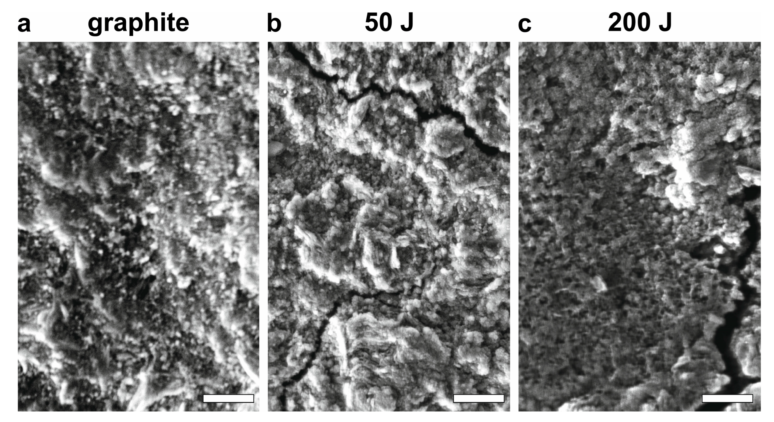
SEM of the precursor MPG-6 graphite (Figure 2a) reveals a coarse surface texture, characterized by morphological features on the order of tens of micrometers. As established in prior studies of atmospheric pressure plasma jet discharges, the presence of such features is instrumental for catalyst-free MWCNT formation, a process facilitated by intense localized heating and ion irradiation [23]. The underlying growth mechanism is governed by discharge-induced surface diffusion of carbon atoms, followed by their condensation at sites of high local curvature. These observations align with the proposed mechanism of discharge-induced surface diffusion; following ion and heat treatment, the formation of globular features along the graphite surface edges and cracks is evident for the 50 J sample (Figure 2b). In the 200 J sample (Figure 2c), a more efficient surface treatment is indicated by the widening of existing cracks and the emergence of larger globular aggregates, resulting from the coalescence of smaller features.

3.2. Elemental Composition

EDX analysis of the precursor MPG-6 graphite revealed a composition of 94.0 ± 0.2 at.% carbon and 5.8 ± 0.2 at.% nitrogen, with trace amounts (~0.2 at.%) of other elements (Si, S, Fe). This non-trivial nitrogen content is characteristic of the industrial-grade material, likely originating from its precursor compounds and manufacturing process, and is consistent with the known challenges of quantifying light elements in a carbon-dominated matrix via EDX. Following irradiation, the composition shifted to 91.5 ± 0.6 at.% C, 8.4 at.% O, and ~0.2 at.% of other elements (Si, S, Fe). This slight oxidation is attributed to surface development and plasma-induced sputtering of carbon, which generates dangling bonds that are subsequently saturated by atmospheric oxygen [26].

3.3. TEM and Electron Diffraction Studies

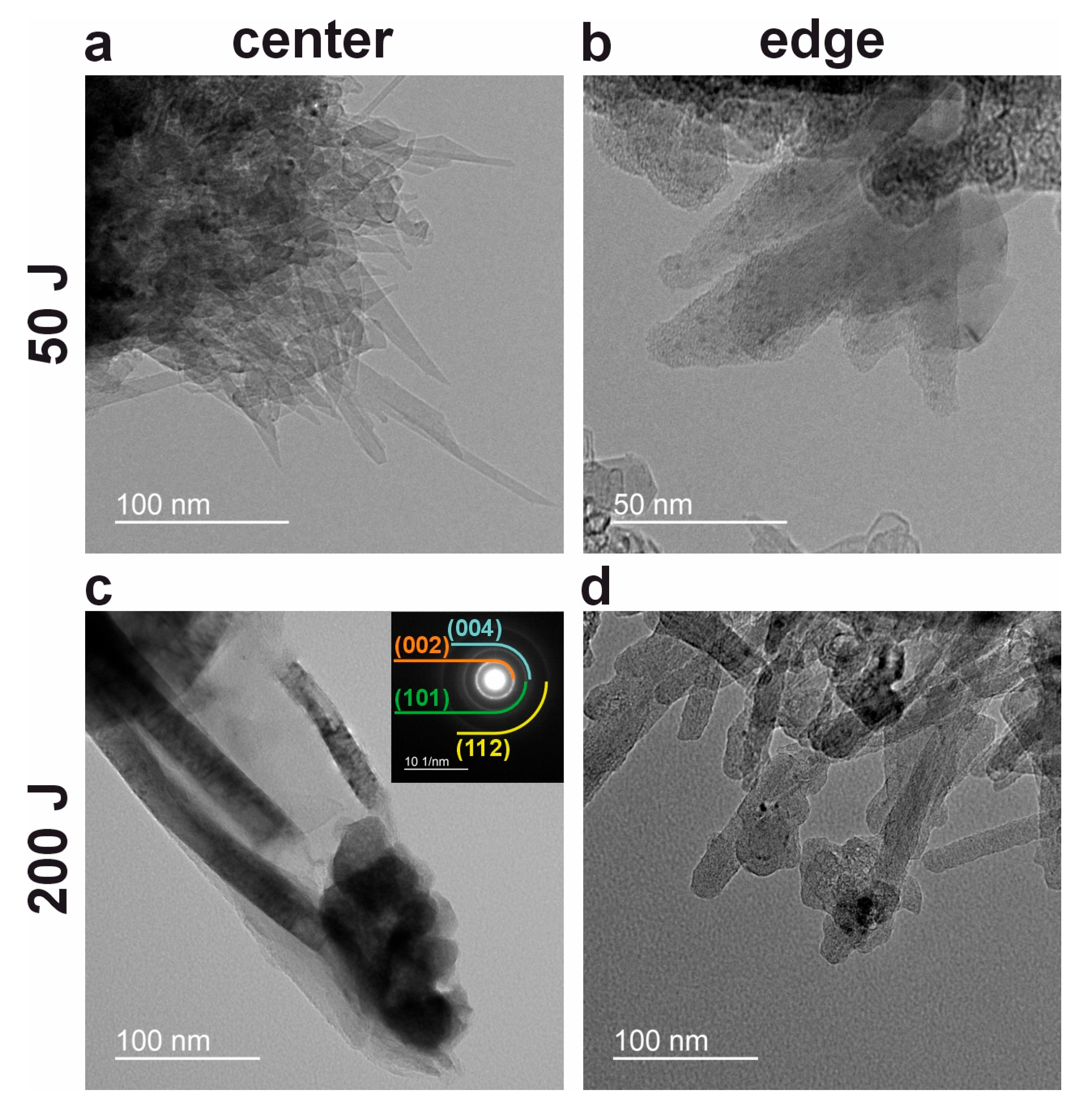
Building on the surface morphology observed via SEM, TEM provides deeper insights into nanoscale structural variations. TEM analysis revealed significant structural heterogeneity, both between different samples and across distinct regions within a single sample. TEM images acquired from the center of the 50 J sample show MWCNT bundles with widths of 8–15 nm and lengths of 50–150 nm (Figure 3a). Near the edge of the same sample, the bundles measure 12–20 nm in width and 50–80 nm in length (Figure 3b). In addition to these dimensional differences, the edge regions exhibit irregular morphology and dark inclusions, indicative of enhanced structural inhomogeneity. A pronounced contrast is observed in the 200 J sample, where the center region contains 20–30 nm wide bundles reaching 100–200 nm in length (Figure 3c), while the edge consists of assemblies with comparable dimensions but markedly more irregular morphology (Figure 3d). The characteristic ring pattern shown in the inset of Figure 3c confirms the polycrystalline nature of the MWCNTs across all samples, with distinct reflections corresponding to the (002) at 3.4 Å, (101) at 2.1 Å, (004) at 1.8 Å, and (112) at 1.2 Å planes [23]. Beyond these polycrystalline signatures, electron diffraction patterns from different regions further reveal structural diversity. The 50 J sample, for instance, exhibits a mix of polycrystalline rings and discrete single-crystal spots (Figure S1a), suggesting the coexistence of small and large, well-oriented MWCNT clusters. In contrast, the diffraction of 200 J sample shown in Figure S1b displays sharp reflections indicative of highly oriented, graphitized MWCNT bundles—(002) at 3.4 Å, (004) at 1.7 Å, (006) at 1.1 Å, and (008) at 0.9 Å. This pronounced morphological and crystallographic variability points to underlying structural modifications, which were further examined using Raman spectroscopy.

3.4. Vibrational Spectroscopy

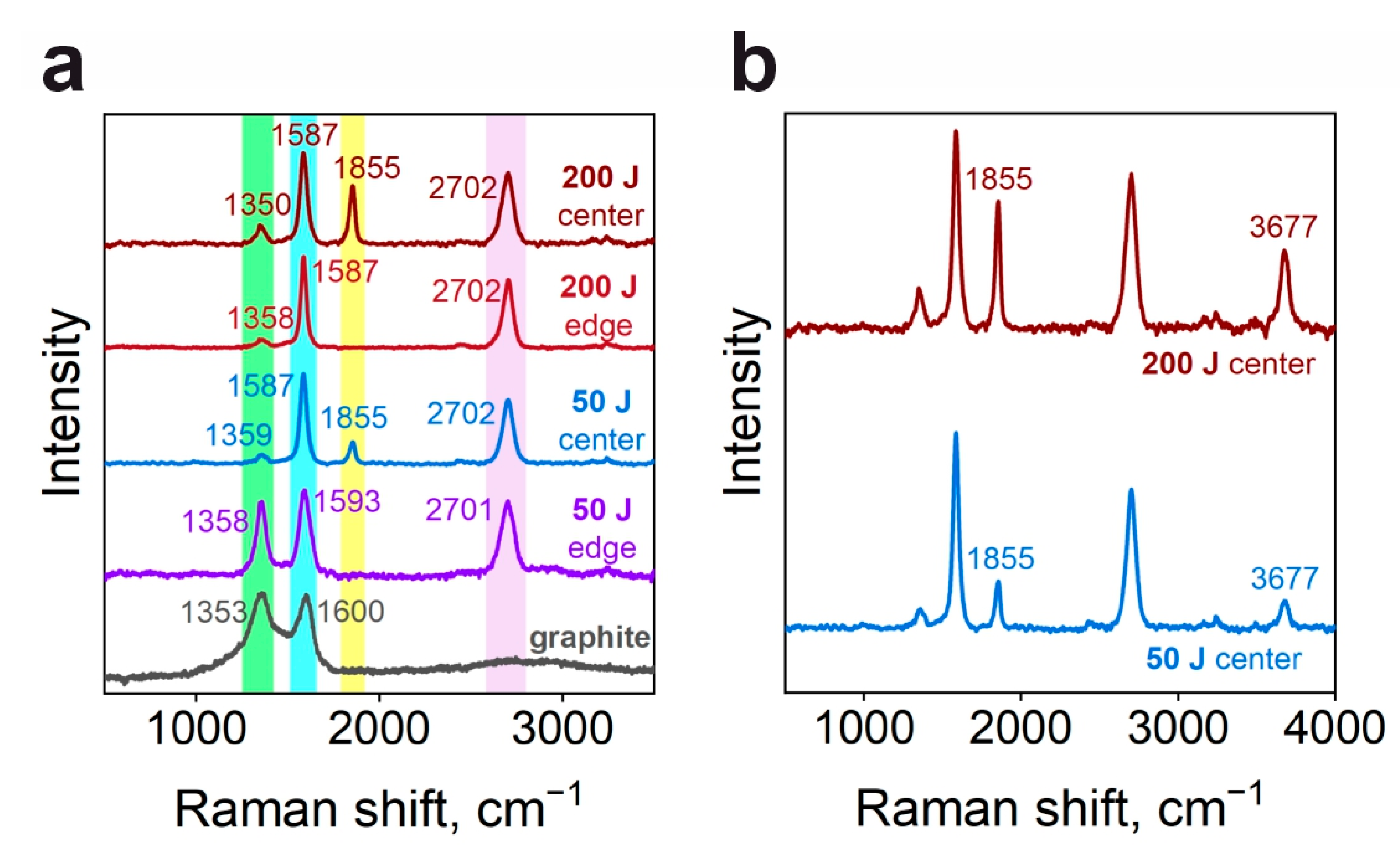
Raman spectroscopy of the precursor MPG-6 graphite presented in Figure 4a exhibits broad D and G bands, centered at approximately 1353 cm−1 and 1600 cm−1, which are associated with disorder-induced breathing modes and in-plane stretching vibrations of graphitic hexagons, respectively [27,28]. In contrast, the spectra acquired from the edge regions of both the 50 J and 200 J samples display features characteristic of multi-walled carbon nanotubes, manifested as narrow D and G bands located at 1358 cm−1 and between 1587–1593 cm−1, alongside a broader 2D band near 2702 cm−1 [23]. The carbon nanotubes at the edge of the 50 J sample, however, indicate a higher degree of structural disorder, as evidenced by an intensity ratio of the D to G band of ID/IG = 0.84, compared to a ratio of ID/IG = 0.12 for the 200 J sample edge. This trend is consistent with transmission electron microscopy observations, which revealed inhomogeneous bundles at the edge of the 50 J sample and assemblies exhibiting a single-crystalline diffraction pattern at the edge of the 200 J sample.
The vibrational signatures from the sample centers differ considerably, exhibiting a distinct peak at 1855 cm−1 attributed to the longitudinal optical (LO) phonon mode of carbon chains confined within nanotubes [22]. This chain-related feature is more pronounced in the high-energy 200 J sample. A second-order 2LO peak, located at 3677 cm−1, was consistently detected in carbyne-containing samples, and its intensity correlates with that of the first-order line (Figure 4b). The position of this 2LO peak is significantly redshifted from twice the wavenumber of the first-order LO phonon (2 × 1855 = 3710 cm−1) by Δ = 33 cm−1, providing clear evidence of vibrational anharmonicity [29]. To quantify this effect, we estimate the anharmonicity constant by modeling the carbyne chain as a Morse oscillator. Using the observed frequencies, the anharmonicity constant is calculated to be xe ≈ 0.0089. This substantial anharmonicity is consistent with the values obtained for strongly anharmonic crystals, such as wurtzite MgZnO (xe = 0.011(1)) [30], and with recent work that identifies anharmonic effects as a governing factor in the interaction between confined carbyne and its nanotube container [31]. The agreement between our experimentally derived xe and the theoretical expectations for such a system confirms the pronounced anharmonic character of the confined linear carbon chain.
Other quantitative parameters of obtained Raman spectra are presented in Table 2. Relative intensities correspond to the fractional areas of the individual peaks, obtained by normalization against the cumulative area of all fitting components. The considerable narrowing of the Raman linewidths from the edge to the center of the discharge zone indicates that structural ordering is enhanced by the localized ion and heat flux.

4. Discussion

4.1. Heat-Mediated Self-Assembly of Carbyne Chains Encapsulated in MWCNT

Considering the MWCNT-enriched area of 0.5 cm2 revealed by SEM studies (Figure 1b), we assessed that CNT formation takes place at the energy density of 0.1–4 kJ/cm2 in the assembled setup. This aligns with the energy densities of 0.5–4.7 kJ/cm2 reported for similar processes [23,32]. In ref. [23], we suggested CNT formation mechanism through discharge-induced surface diffusion of carbon atoms followed by condensation at local curvature minima. For the structures investigated in current work, is confirmed by SEM studies, as discussed in Section 3.1. Separately, carbyne encapsulated inside carbon nanotubes has been synthesized via direct current arc discharge evaporation of pure carbon electrodes in a hydrogen gas atmosphere [17]. In this approach, the confined space within a forming nanotube serves as a reactor that facilitates reactions between carbon species, providing sufficient energy to surpass barriers for carbon-carbon bond formation and thus fostering carbyne chain growth [33]. This confinement provides a unique method for stabilizing highly reactive carbyne chains. However, such conventional discharge synthesis techniques provide limited control over the spatial distribution of carbyne@MWCNT structures, a limitation that has curtailed the technological development of encapsulated carbyne.
The spatial divergence in nanotube structure and carbyne encapsulation between the center and edge regions, as well as between the 50 J and 200 J samples, is primarily attributed to the gradient in localized heat flux. The total discharge energy (50 J or 200 J) is a macroscopic control parameter that dictates the total enthalpy delivered to the surface. This energy is not deposited uniformly; the geometry of the plasma jet results in a high energy density at the center of the interaction zone, which dissipates radially towards the edge, as indicated by Figure 1b–e. This creates a corresponding spatial gradient in the local processing temperature, which governs the kinetics of carbon atom surface diffusion, reorganization, and ultimately, the growth of ordered nanostructures. While the plasma jet is a complex medium involving gradients in species concentration, ion flux, and electric fields, the thermal energy gradient is considered the dominant factor for several reasons. First, the formation of carbyne chains inside MWCNTs at the center of the 200 J sample, where thermal effects are most intense, is a signature of high temperature treatment [33]. Second, the difference in morphology between the center and edge of a single sample occurs under a largely uniform heat flux, underscoring the role of local temperature. Although ion bombardment can contribute to surface activation [34], its potential disruptive effects are superseded by the beneficial thermal annealing at higher energy densities, leading to improved structural order. Therefore, the spatial profile of the heat flux serves as the principal mediator for the guided self-assembly reported here.
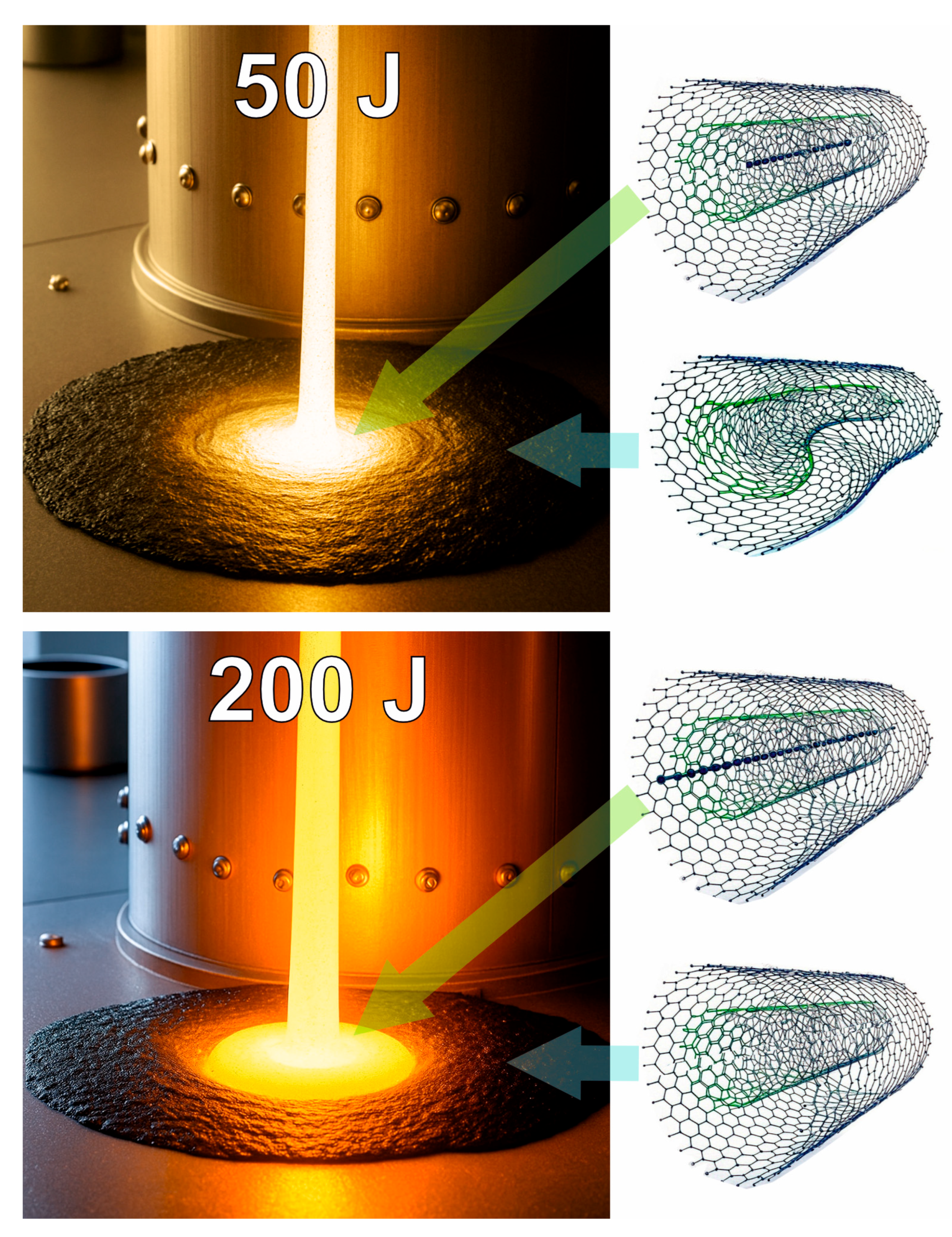
Thus, localized capillary discharge jets offer a platform for spatially controlled synthesis of MWCNTs, enabling the attainment of temperatures optimal for carbyne formation within a confined region. At a discharge energy of 50 J, low-intensity carbyne formation is observed primarily at the center of the treated zone, where heat accumulation is sufficient to drive the reaction. Toward the periphery of the discharge, however, heat dissipation into the untreated surrounding regions compromises these conditions, resulting in the formation of disordered MWCNT aggregates (Figure 5, top panel). In contrast, the higher-energy 200 J discharge promotes improved structural ordering, yielding longer and less defective nanotubes. This enhances the formation of carbyne near the center of the treated zone, though carbyne remains absent at the outer edge (Figure 5, bottom panel). These results demonstrate that the spatial profile of the heat flux directly mediates the growth of carbon chains, establishing a means for exerting spatial control over carbyne@MWCNT synthesis.

4.2. Implications and Perspectives

The exceptionally high Raman scattering cross-section of carbyne chains makes them exceptional candidates for nanoscale temperature sensing, as precise thermal measurements can be derived from the variation in the Stokes/anti-Stokes intensity ratio [10,35]. The feasibility of using the carbyne LO mode for nanoscale temperature sensing has been experimentally validated in Ref. [35], where the anti-Stokes Raman scattering of individual carbyne chains was used for local thermometry. Given the exceptionally high Raman scattering cross-section of carbyne, which significantly exceeds that of graphite or carbon nanotubes [36], our spatially defined carbyne@MWCNT arrays represent a promising platform for advancing this concept towards integrated sensor applications.
To leverage the temperature sensing via confined carbyne, we propose the use of capillary discharge jets to fabricate spatially defined arrays of carbyne@MWCNT temperature microprobes. These arrays can utilize the resonant Raman scattering of confined carbyne to enable contact-free, nanoscale thermal mapping (see Figure 6a). A key advantage of this perspective approach is the ability to integrate these probes directly onto graphite surfaces without compromising their inherent thermal conductivity and stability, thus enhancing real-time thermal monitoring in environments where graphite is commonly used (Figure 6b–d). This carbyne-based sensing platform can potentially offer a solution to several inherent limitations of conventional infrared (IR) thermography, such as emissivity variability due to surface roughness, interference from surrounding radiation sources, and atmospheric absorption of IR radiation [37,38]. The feasibility of implementing this technology is further supported by recent advancements in portable Raman spectrometers [39,40] and fiber-optic systems capable of Raman mapping [41], which together pave the way for precise Stokes/anti-Stokes thermometry in diverse graphite-based applications.
For instance, graphite is a key component in brake linings, shoes, and clutch materials due to its ability to modulate friction and efficiently dissipate heat. Nonetheless, the performance and longevity of these components are often compromised by thermal cracking induced by localized temperature spikes and uneven heat distribution [42,43]. The integration of the proposed carbyne@MWCNT micro-probes (Figure 6b) onto these graphite surfaces could potentially address this issue by enabling real-time detection of these critical thermal gradients. Such precise, localized temperature monitoring would facilitate predictive maintenance strategies, enhance operational safety, and provide vital thermal data for advanced driver-assistance systems in heavy-duty and high-performance vehicles.
Similarly, in high-temperature industrial settings, the real-time monitoring capabilities of carbyne@MWCNT micro-probes hold promise for advancing thermal management. Graphite is extensively employed in the manufacturing of refractories for furnaces, kilns, and crucibles, as well as in susceptors, owing to its exceptional thermal resistance and capacity to extend component longevity [44,45,46,47]. Embedding carbyne@MWCNT micro-probes into these graphite linings or components could provide real-time localized temperature data. This would allow for the optimization of heat distribution, early detection of refractory failures or hot spots, and a significant improvement in operational safety and efficiency in critical processes such as steelmaking and metal processing.
Beyond mechanical and industrial applications, integrated thermal sensing also holds significant potential for advancing thermal management in electronic systems. Graphite plays a crucial role in thermal management components including heat sinks, electrodes, and conductive additives for high-power electronics, batteries, and LEDs, where its high thermal conductivity significantly enhances heat dissipation [48,49,50,51]. The integration of carbyne@MWCNT micro-probes onto these graphite surfaces would enable precise, nanoscale temperature mapping. This capability could dramatically improve device reliability and energy efficiency by informing dynamic thermal management strategies, preventing overheating in critical applications ranging from consumer electronics to advanced high-power systems.
Despite the promising potential of carbyne@MWCNT micro-probes for advanced thermal sensing, several challenges must be overcome before practical implementation can be realized. First, the spatial resolution and uniformity of probe arrays produced via capillary discharge jet require further optimization. The current synthesis method exhibits a strong dependence on discharge energy and spatial position (center versus edge), resulting in structural inhomogeneity. Achieving reproducible, highly ordered, and dense arrays over large areas and across varying graphite substrates remains a significant materials engineering challenge. Furthermore, the synthesis outcome is likely sensitive to the properties of the graphite substrate itself, such as its surface morphology (roughness, grain boundaries), crystallographic orientation, purity, and density, which govern local heat dissipation, carbon atom surface diffusion, and nucleation efficiency. Systematically controlling these substrate parameters will be key to achieving uniform synthesis across different graphite grades and forms. Second, the long-term stability of encapsulated carbyne chains under harsh operational conditions, such as intense mechanical wear, oxidative atmospheres, or repeated thermal cycling, has not been established. This is particularly critical for applications in braking systems or high-temperature furnaces. Third, integrating these nanostructured probes into industrial components without compromising their mechanical integrity or primary functionality (e.g., the frictional performance of brake linings) presents a substantial engineering hurdle. Finally, although Raman-based readout is highly advanced, current systems are predominantly external and laboratory-bound. The development of compact, robust, and cost-effective integrated optical readout systems capable of real-time, in-situ monitoring in industrial environments is essential for widespread adoption. Addressing these limitations will be paramount to bridging the gap between laboratory demonstration and scalable industrial deployment of carbyne-based thermal sensors.
Looking forward, the structural inhomogeneity observed in the current study, while useful for demonstrating spatial control, presents a key challenge for the scalable fabrication of uniform device arrays. Based on the principle that inhomogeneity arises from the radial gradient in plasma energy and heat flux density, several engineering modifications to the capillary discharge system can be proposed to achieve a more uniform treatment zone. Firstly, current cylindrical capillary produces a jet with a natural Gaussian-like energy profile. Implementing a converging-diverging (de Laval) nozzle design could reshape the plasma flow. Such a nozzle is known in plasma dynamics to produce a more uniform velocity and temperature profile across its diameter by controlling the expansion of the supersonic plasma plume [52,53]. This would result in a more spatially uniform heat flux at the impingement surface. Second, introducing a controlled co-axial sheath gas flow around the primary plasma jet could serve to collimate the plume and reduce its turbulent interaction with the ambient atmosphere, thereby stabilizing its geometry and energy distribution upon surface impact [54]. Third, introduction of hydrocarbon precursors into the discharge region could serve a dual purpose. Their decomposition would provide a more uniform and controllable gaseous carbon source, supplementing the carbon from the graphite electrode ablation [55]. This could decouple the carbyne formation yield from local variations in substrate erosion, promoting more consistent growth across the treated area, as demonstrated in other confined synthesis routes. These proposed modifications, which are feasible extensions of our current experimental setup, are expected to confine the high-energy density region to a more uniform area, thereby promoting the growth of consistent carbyne@MWCNT structures.

5. Conclusions

This work presents a scalable, one-step approach for the energy-dependent synthesis of spatially defined carbyne@MWCNT heterostructures on graphite substrates using a capillary discharge jet. The structural and spectroscopic characterization confirms that the spatial variation in heat flux directly mediates the nanotube quality and the successful formation of carbyne chains, with the highest carbyne fraction achieved at the center of the high-energy (200 J) discharge. We believe this approach allows for the formation of encapsulated carbyne-based microprobe arrays, thus offering a powerful new strategy for integrating carbyne into functional devices, paving the way for their application in technology.

Supplementary Materials

The following supporting information can be downloaded at: https://www.mdpi.com/article/10.3390/c11040074/s1, Figure S1: Selected-area electron diffraction patterns confirming structural diversity in 50 J and 200 J samples. (a) 50 J sample. Positions of MWCNT-related (002), (101), (004), and (112) reflections (from center to edge) are identified. (b) 200 J sample. Graphitic (002), (004), (006), and (008) reflections are identified by circles.

Author Contributions

Conceptualization, O.A.S.; Data curation, I.A.Z. and A.A.K.; Formal analysis, I.A.Z.; Funding acquisition, I.A.Z.; Methodology, O.A.S., V.A.B. and A.S.P.; Project administration, O.A.S.; Resources, V.A.B., A.S.P., A.A.K. and V.L.B.; Software, A.A.K.; Supervision, O.A.S. and V.L.B.; Validation, A.S.P., A.A.K. and V.L.B.; Visualization, I.A.Z.; Writing—original draft, I.A.Z.; Writing—review & editing, O.A.S. and A.S.P. All authors have read and agreed to the published version of the manuscript.

Funding

The research was funded by the Russian Science Foundation (project № 24-22-00152).

Data Availability Statement

The original contributions presented in this study are included in the article/Supplementary Materials. Further inquiries can be directed to the corresponding author.

Acknowledgments

SEM studies were carried out by A. Tatarintsev (Faculty of Physics, M.V. Lomonosov Moscow State University). During the preparation of this manuscript, the authors used Grok, version 4, for the purposes of generation of some fragments of Figure 5. The authors have reviewed and edited the output and take full responsibility for the content of this publication.

Conflicts of Interest

The authors declare no conflicts of interest.

References

  1. Ali, Z.; Yaqoob, S.; Yu, J.; D’Amore, A. Critical Review on the Characterization, Preparation, and Enhanced Mechanical, Thermal, and Electrical Properties of Carbon Nanotubes and Their Hybrid Filler Polymer Composites for Various Applications. Compos. Part C Open Access 2024, 13, 100434. [Google Scholar] [CrossRef]
  2. Zhang, C.; Ling, Y.; Zhang, X.; Liang, M.; Zou, H. Ultra-Thin Carbon Fiber Reinforced Carbon Nanotubes Modified Epoxy Composites with Superior Mechanical and Electrical Properties for the Aerospace Field. Compos. Part. A Appl. Sci. Manuf. 2022, 163, 107197. [Google Scholar] [CrossRef]
  3. Xing, G.; Xu, Y.; Huang, J.; Lu, Y.; Miao, P.; Chindasiriphan, P.; Jongvivatsakul, P.; Ma, K. Research on the Mechanical Properties of Steel Fibers Reinforced Carbon Nanotubes Concrete. Constr. Build. Mater. 2023, 392, 131880. [Google Scholar] [CrossRef]
  4. Hamouda, H.I.; Abdel-Ghafar, H.M.; Mahmoud, M.H.H. Multi-Walled Carbon Nanotubes Decorated with Silver Nanoparticles for Antimicrobial Applications. J. Environ. Chem. Eng. 2021, 9, 105034. [Google Scholar] [CrossRef]
  5. Kumar, S.; Sidhu, H.K.; Paul, A.K.; Bhardwaj, N.; Thakur, N.S.; Deep, A. Bioengineered Multi-Walled Carbon Nanotube (MWCNT) Based Biosensors and Applications Thereof. Sens. Diagn. 2023, 2, 1390–1413. [Google Scholar] [CrossRef]
  6. Nag, A.; Alahi, M.E.E.; Mukhopadhyay, S.C.; Liu, Z. Multi-Walled Carbon Nanotubes-Based Sensors for Strain Sensing Applications. Sensors 2021, 21, 1261. [Google Scholar] [CrossRef] [PubMed]
  7. Chen, Z.; Zhao, J.; Cao, J.; Zhao, Y.; Huang, J.; Zheng, Z.; Li, W.; Jiang, S.; Qiao, J.; Xing, B.; et al. Opportunities for Graphene, Single-Walled and Multi-Walled Carbon Nanotube Applications in Agriculture: A Review. Crop Des. 2022, 1, 100006. [Google Scholar] [CrossRef]
  8. Ramachandran, K.; Boopalan, V.; Bear, J.C.; Subramani, R. Multi-Walled Carbon Nanotubes (MWCNTs)-Reinforced Ceramic Nanocomposites for Aerospace Applications: A Review. J. Mater. Sci. 2022, 57, 3923–3953. [Google Scholar] [CrossRef]
  9. Zhao, Y.; Luo, Q.; Wu, J.; Sui, C.; Tong, L.; He, X.; Wang, C. Mechanical Properties of Helically Twisted Carbyne Fibers. Int. J. Mech. Sci. 2020, 186, 105823. [Google Scholar] [CrossRef]
  10. Cui, W.; Shi, L. Synthesis and Properties of Confined Carbyne and Beyond. Adv. Colloid. Interface Sci. 2025, 342, 103519. [Google Scholar] [CrossRef]
  11. Berdiyorov, G.R.; Khalilov, U.; Hamoudi, H.; Neyts, E.C. Effect of Chemical Modification on Electronic Transport Properties of Carbyne. J. Comput. Electron. 2021, 20, 848–854. [Google Scholar] [CrossRef]
  12. Karthik, H.J.; Sarga, P.K.; Bhattacharyya, S. Electronic Phase Transition, Vibrational Properties and Structural Stability of Single and Two Polyyne Chains under External Electric Field. Carbon Trends 2024, 14, 100319. [Google Scholar] [CrossRef]
  13. Shi, L.; Rohringer, P.; Suenaga, K.; Niimi, Y.; Kotakoski, J.; Meyer, J.C.; Peterlik, H.; Wanko, M.; Cahangirov, S.; Rubio, A.; et al. Confined Linear Carbon Chains as a Route to Bulk Carbyne. Nat. Mater. 2016, 15, 634–639. [Google Scholar] [CrossRef] [PubMed]
  14. Zhang, Y.; Zhao, J.; Fang, Y.; Liu, Y.; Zhao, X. Preparation of Long Linear Carbon Chain inside Multi-Walled Carbon Nanotubes by Cooling Enhanced Hydrogen Arc Discharge Method. Nanoscale 2018, 10, 17824–17833. [Google Scholar] [CrossRef]
  15. Song, I.; Park, C.; Hong, M.; Baik, J.; Shin, H.; Choi, H.C. Patternable Large-Scale Molybdenium Disulfide Atomic Layers Grown by Gold-Assisted Chemical Vapor Deposition. Angew. Chem. Int. Ed. 2014, 53, 1266–1269. [Google Scholar] [CrossRef]
  16. Gwo, S.; Chen, H.-Y.; Lin, M.-H.; Sun, L.; Li, X. Nanomanipulation and Controlled Self-Assembly of Metal Nanoparticles and Nanocrystals for Plasmonics. Chem. Soc. Rev. 2016, 45, 5672–5716. [Google Scholar] [CrossRef]
  17. Zhao, X.; Ando, Y.; Liu, Y.; Jinno, M.; Suzuki, T. Carbon Nanowire Made of a Long Linear Carbon Chain Inserted Inside a Multiwalled Carbon Nanotube. Phys. Rev. Lett. 2003, 90, 187401. [Google Scholar] [CrossRef]
  18. Chang, W.; Liu, F.; Liu, Y.; Zhu, T.; Fang, L.; Li, Q.; Liu, Y.; Zhao, X. Smallest Carbon Nanowires Made Easy: Long Linear Carbon Chains Confined inside Single-Walled Carbon Nanotubes. Carbon 2021, 183, 571–577. [Google Scholar] [CrossRef]
  19. Zhao, C.; Kitaura, R.; Hara, H.; Irle, S.; Shinohara, H. Growth of Linear Carbon Chains inside Thin Double-Wall Carbon Nanotubes. J. Phys. Chem. C 2011, 115, 13166–13170. [Google Scholar] [CrossRef]
  20. Asaka, K.; Toma, S.; Saito, Y. Raman Spectroscopy and Transmission Electron Microscopy of Long Linear Atomic Carbon Chains Generated by Field Electron Emission Accompanied with Electrical Discharge of Carbon Nanotube Films. SN Appl. Sci. 2019, 1, 493. [Google Scholar] [CrossRef]
  21. Shi, L.; Senga, R.; Suenaga, K.; Chimborazo, J.; Ayala, P.; Pichler, T. Photothermal Synthesis of Confined Carbyne. Carbon 2021, 182, 348–353. [Google Scholar] [CrossRef]
  22. Chen, Y.; Tang, K.; Zhang, W.; Cao, H.; Zhang, H.; Feng, Y.; Cui, W.; Hu, Y.; Shi, L.; Yang, G. A Universal Method to Transform Aromatic Hydrocarbon Molecules into Confined Carbyne inside Single-Walled Carbon Nanotubes. ACS Nano 2025, 19, 12146–12154. [Google Scholar] [CrossRef]
  23. Baidak, V.A.; Zavidovskiy, I.A.; Tatarintsev, A.A.; Bychkov, V.L.; Streletskiy, O.A. Energy-Effective Synthesis of Multiwalled Carbon Nanotubes via Ambient-Air Atmospheric-Pressure Plasma Jet Treatment of Graphite. Surfaces 2025, 8, 16. [Google Scholar] [CrossRef]
  24. Pashchina, A.S.; Efimov, A.V.; Chinnov, V.F. Optical Investigations of the Multicomponent Plasma of the Capillary Discharge: Subsonic Outflow Regime. High Temp. 2016, 54, 488–502. [Google Scholar] [CrossRef]
  25. Pashchina, A.S.; Efimov, A.V.; Chinnov, V.F. Optical Investigations of Multicomponent Plasma of Capillary Discharge. Supersonic Outflow Regime. High Temp. 2017, 55, 650–664. [Google Scholar] [CrossRef]
  26. Evseev, A.P.; Vorobyeva, E.A.; Balakshin, Y.V.; Kushkina, K.D.; Stepanov, A.V.; Chernysh, V.S.; Chechenin, N.G.; Shemukhin, A.A. MWCNT-Based Surfaces with Tunable Wettability Obtained by He+ Ion Irradiation. Surf. Interfaces 2021, 23, 100955. [Google Scholar] [CrossRef]
  27. Streletskiy, O.A.; Zavidovskiy, I.A.; Nuriahmetov, I.F.; Nishchak, O.Y.; Pavlikov, A.V.; Savchenko, N.F. Resistive Gas Sensors Based on Porous Sp-Containing Films Obtained by Dehydrohalogenation of PVDC and PVDC-PVC Copolymer. C 2023, 9, 82. [Google Scholar] [CrossRef]
  28. Zavidovskiy, I.A.; Streletskiy, O.A.; Nuriahmetov, I.F.; Nishchak, O.Y.; Savchenko, N.F.; Tatarintsev, A.A.; Pavlikov, A.V. Highly Selective Polyene-Polyyne Resistive Gas Sensors: Response Tuning by Low-Energy Ion Irradiation. J. Compos. Sci. 2023, 7, 156. [Google Scholar] [CrossRef]
  29. Sidorov, N.V.; Palatnikov, M.N.; Gorelik, V.S.; Sverbil, P.P. Second-Order Raman Spectra of a LiNbO3:Tb Crystal. Spectrochim. Acta Part A Mol. Biomol. Spectrosc. 2022, 266, 120445. [Google Scholar] [CrossRef]
  30. Huso, J.; Morrison, J.L.; Bergman, L.; McCluskey, M.D. Anharmonic Resonant Raman Modes in Mg0.2Zn0.8O. Phys. Rev. B 2013, 87, 125205. [Google Scholar] [CrossRef]
  31. Parth, E.; Corradini, A.; Cui, W.; Romanin, D.; Schuster, C.; Freytag, C.; Shi, L.; Yanagi, K.; Calandra, M.; Pichler, T. Anharmonic Effects Control Interaction of Carbyne Confined in Carbon Nanotubes Shaping Their Vibrational Properties. Nat. Commun. 2025, 16, 4797. [Google Scholar] [CrossRef]
  32. Chen, J.-Z.; Wang, C.; Hsu, C.-C.; Cheng, I.-C. Ultrafast Synthesis of Carbon-Nanotube Counter Electrodes for Dye-Sensitized Solar Cells Using an Atmospheric-Pressure Plasma Jet. Carbon 2016, 98, 34–40. [Google Scholar] [CrossRef]
  33. Deng, Y.; Cranford, S.W. Mapping Temperature and Confinement Dependence of Carbyne Formation within Carbon Nanotubes. Carbon 2019, 141, 209–217. [Google Scholar] [CrossRef]
  34. Netcheva, S.; Bertrand, P. Surface Topography Development of Thin Polystyrene Films under Low Energy Ion Irradiation. Nucl. Instrum. Methods Phys. Res. Sect. B Beam Interact. Mater. At. 1999, 151, 129–134. [Google Scholar] [CrossRef]
  35. Tschannen, C.D.; Frimmer, M.; Gordeev, G.; Vasconcelos, T.L.; Shi, L.; Pichler, T.; Reich, S.; Heeg, S.; Novotny, L. Anti-Stokes Raman Scattering of Single Carbyne Chains. ACS Nano 2021, 15, 12249–12255. [Google Scholar] [CrossRef] [PubMed]
  36. Tschannen, C.D.; Gordeev, G.; Reich, S.; Shi, L.; Pichler, T.; Frimmer, M.; Novotny, L.; Heeg, S. Raman Scattering Cross Section of Confined Carbyne. Nano Lett. 2020, 20, 6750–6755. [Google Scholar] [CrossRef]
  37. Lahiri, B.B.; Bagavathiappan, S.; Jayakumar, T.; Philip, J. Medical Applications of Infrared Thermography: A Review. Infrared Phys. Technol. 2012, 55, 221–235. [Google Scholar] [CrossRef] [PubMed]
  38. Kim, H.; Lamichhane, N.; Kim, C.; Shrestha, R. Innovations in Building Diagnostics and Condition Monitoring: A Comprehensive Review of Infrared Thermography Applications. Buildings 2023, 13, 2829. [Google Scholar] [CrossRef]
  39. Barnett, P.D.; Angel, S.M. Miniature Spatial Heterodyne Raman Spectrometer with a Cell Phone Camera Detector. Appl. Spectrosc. 2017, 71, 988–995. [Google Scholar] [CrossRef]
  40. Crocombe, R.A.; Kammrath, B.W.; Leary, P.E. Portable Raman Spectrometers: How Small Can They Get? Spectroscopy 2023, 38, 32–40. [Google Scholar] [CrossRef]
  41. Yang, W.; Knorr, F.; Latka, I.; Vogt, M.; Hofmann, G.O.; Popp, J.; Schie, I.W. Real-Time Molecular Imaging of near-Surface Tissue Using Raman Spectroscopy. Light Sci. Appl. 2022, 11, 90. [Google Scholar] [CrossRef]
  42. Xu, Z.; Wang, G.; Li, Y. Thermal Cracking and Friction Performance of Two Kinds of Compacted Graphite Iron Brake Discs under Intensive Braking Conditions. Metals 2024, 14, 332. [Google Scholar] [CrossRef]
  43. Wang, G.; Xu, Z.; Liu, Z.; Chen, X.; Li, Y. Thermal Fatigue and Wear of Compacted Graphite Iron Brake Discs with Various Thermomechanical Properties. China Foundry 2024, 21, 248–256. [Google Scholar] [CrossRef]
  44. Zhu, T.; Li, Y.; Sang, S. Heightening Mechanical Properties and Thermal Shock Resistance of Low–Carbon Magnesia–Graphite Refractories through the Catalytic Formation of Nanocarbons and Ceramic Bonding Phases. J. Alloys Compd. 2019, 783, 990–1000. [Google Scholar] [CrossRef]
  45. Mukhopadhyay, S.; Dana, K.; Moitra, S.; BasuMallick, S.; Mukhopadhyay, T.K. Thermal and Thermomechanical Characteristics of Monolithic Refractory Composite Matrix Containing Surface-Modified Graphite. Ceram. Int. 2016, 42, 6015–6024. [Google Scholar] [CrossRef]
  46. Parvej; Sharma, A.K. On Heating Characteristics and Mass Depletion of Structurally Different SiC and Graphite Susceptors under Microwave Irradiation. Mater. Chem. Phys. 2025, 341, 130928. [Google Scholar] [CrossRef]
  47. Suriapparao, D.V.; Nagababu, G.; Yerrayya, A.; Sridevi, V. Optimization of Microwave Power and Graphite Susceptor Quantity for Waste Polypropylene Microwave Pyrolysis. Process Saf. Environ. Prot. 2021, 149, 234–243. [Google Scholar] [CrossRef]
  48. Alhusseny, A.; Al-Aabidy, Q.; Al-Zurfi, N.; Nasser, A.; Aljanabi, M. Cooling of High-Performance Electronic Equipment Using Graphite Foam Heat Sinks. Appl. Therm. Eng. 2021, 191, 116844. [Google Scholar] [CrossRef]
  49. Zhao, Y.; Xue, K.; Tan, T.; Yu, D.Y.W. Thermal Stability of Graphite Electrode as Cathode for Dual-Ion Batteries. ChemSusChem 2023, 16, e202201221. [Google Scholar] [CrossRef]
  50. Tuersun, Y.; Luo, P.; Chen, Y.; Huang, X.; Huang, M.; Chu, S. Preparation and Surface Modification of Vertically Structured Indium/Graphite Elastomer Thermal Pad for Effective Heat Dissipation. Compos. Commun. 2025, 58, 102518. [Google Scholar] [CrossRef]
  51. Fu, H.; Xiao, Y.; Li, P.; Qian, W.; Li, D.; Zhao, X.; He, D. Ultrasonic-Assisted Soldering for Graphite Films as Heat Sinks with Durably Superior Heat Dissipating Efficiency. Adv. Compos. Hybrid Mater. 2022, 5, 2154–2162. [Google Scholar] [CrossRef]
  52. Durif, O. Design of de Laval Nozzles for Gas-Phase Molecular Studies in Uniform Supersonic Flow. Phys. Fluids 2022, 34, 013605. [Google Scholar] [CrossRef]
  53. Lu, H.; Ma, Y.; Peng, B.; Xin, J.; Tian, Z.; Guo, S.; Li, D. Performance Differences and Design Method Improvement of Laval Nozzles under Superatmospheric and Subatmospheric Conditions. Phys. Fluids 2025, 37, 096117. [Google Scholar] [CrossRef]
  54. Zheng, G.; Jiang, J.; Wang, X.; Li, W.; Liu, J.; Fu, G.; Lin, L. Nanofiber Membranes by Multi-Jet Electrospinning Arranged as Arc-Array with Sheath Gas for Electrodialysis Applications. Mater. Des. 2020, 189, 108504. [Google Scholar] [CrossRef]
  55. Streletskiy, O.A.; Zavidovskiy, I.A.; Nischak, O.Y.; Pavlikov, A.V. Multiphonon Replicas in Raman Spectra and Conductivity Properties of Carbon Films with Different Concentrations of Sp1-Bonds. Thin Solid Film. 2019, 671, 31–35. [Google Scholar] [CrossRef]
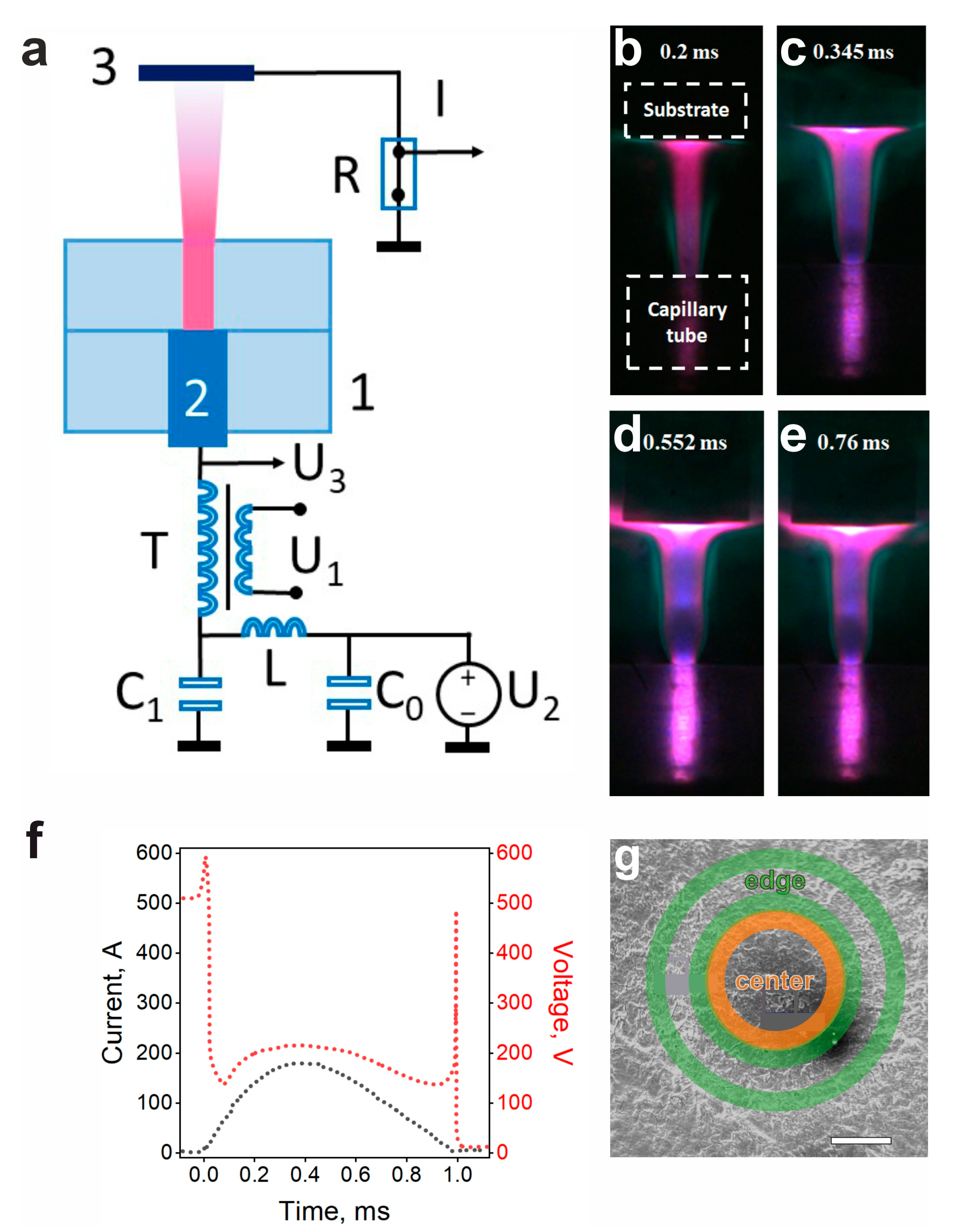
Figure 1. Capillary discharge jet dynamics and surface effect. (a) Electrical circuit of capillary plasma generator. 1: discharge unit; 2: internal electrode (anode); 3: external electrode (graphite sample); U1—trigger pulse inducing up to 60 kV at the secondary winding (pulse duration 20 μs); U2: power supply (400–800 V); U3: oscilloscope for voltage control; R: resistive shunt for current measurement; L: circuit inductance (270 μH), C0: storage capacitor (470 μF); C1: ignition capacitor (1 μF); T: step-up transformer. (be) Time-resolved capillary plasma discharge photographs. (b) 0.2 ms, (c) 0.345 ms, (d) 0.552 ms, (e) 0.75 ms. Time elapsed from the discharge ignition event. (f) Exemplary discharge dynamics of voltage (right axis, red line) and current (left axis, black line). (g) SEM image of the discharge-treated MPG-6 graphite. Scale bar size is 200 μm. Borders of “center” and “edge” areas are marked by orange and green circles, respectively.
Carbon 11 00074 g001
Figure 2. SEM characterization. (a) Irradiated MPG-6 graphite. (b) 50 J sample. (c) 200 J sample. Scale bar size is 10 μm.
Carbon 11 00074 g002
Figure 3. TEM characterization. (a) Center of 50 J sample (magnification 130,000×). (b) Edge of 50 J sample (magnification 260,000×). (c) Center of 200 J sample (magnification 130,000×). (d) Edge of 200 J sample (magnification 130,000×). In the inset, a typical electron diffraction pattern is shown. Miller indices and related diffraction rings are indicated.
Carbon 11 00074 g003
Figure 4. Normalized Raman spectra. Vertical offset is applied to distinguish the lines. Line positions are indicated by numbers. (a) First-order Raman spectra. Green, turquoise, yellow, and rose regions indicate D-line, G-line, LO phonon of carbyne chains, and 2D lines, respectively. (b) First- and second-order Raman spectra of carbyne-containing samples.
Carbon 11 00074 g004
Figure 5. Visualization of heat-mediated spatial divergence of nanotube structure and its variation with discharge energy. Green and blue arrows represent the structure variability in the center and at the edge of the discharge area.
Carbon 11 00074 g005
Figure 6. Concept and perspective applications of spatially distinctive carbyne@MWCNT temperature microprobes. (a) Concept of APPJ-formed Stokes/anti-Stokes temperature sensors formed on graphite surface. (b) Disk brake with a brake shoe with an integrated probe array. (c) Detail of the high-temperature furnace with a microprobe-enhanced graphite susceptor. (d) Electronic circuit with a microprobe-enhanced graphite heat sink.
Carbon 11 00074 g006
Table 1. Discharge parameters.
Capacitance, μF470
Initial voltage, V500–800
Energy stored in the capacitance, J50–200
Capillary surface, mm20.8
Voltage drop, V200–280
Current, A180–320
Discharge duration, ms1
Table 2. Parameters of the Raman spectra fitting. Line positions (kmax), half widths at half maximum (HWHM) and relative intensities of the lines (Irel) are presented.
Linekmax, cm−1HWHM, cm−1Irel, %
50 J edgeD-line1356 ± 129 ± 126 ± 1
G-line1592 ± 131 ± 134 ± 1
2D2699 ± 143 ± 140 ± 1
50 J centerD-line1358 ± 123 ± 14 ± 1
G-line1586 ± 119 ± 139 ± 1
LO1853 ± 114 ± 17 ± 1
2D2701 ± 130 ± 142 ± 1
2LO3677 ± 131 ± 19 ± 1
200 J edgeD-line1359 ± 233 ± 16 ± 1
G-line1586 ± 117 ± 142 ± 1
2D2701 ± 128 ± 152 ± 1
200 J centerD-line1353 ± 125 ± 16 ± 1
G-line1586 ± 121 ± 129 ± 1
LO1852 ± 115 ± 113 ± 1
2D2699 ± 133 ± 135 ± 1
2LO3677 ± 132 ± 117 ± 1
Disclaimer/Publisher’s Note: The statements, opinions and data contained in all publications are solely those of the individual author(s) and contributor(s) and not of MDPI and/or the editor(s). MDPI and/or the editor(s) disclaim responsibility for any injury to people or property resulting from any ideas, methods, instructions or products referred to in the content.