Article

On the Numerical Investigation of Two-Phase Evaporative Spray Cooling Technology for Data Centre Applications

Department of Mechanical, Manufacturing and Biomedical Engineering, Trinity College Dublin, D02 PN40 Dublin, Ireland
*
Author to whom correspondence should be addressed.
Fluids 2024, 9(12), 284; https://doi.org/10.3390/fluids9120284
Submission received: 26 October 2024 / Revised: 15 November 2024 / Accepted: 28 November 2024 / Published: 29 November 2024
(This article belongs to the Special Issue Evaporation, Condensation and Heat Transfer)

Abstract

:
Two-phase evaporative spray cooling technology can significantly reduce power consumption in data centre cooling applications. However, the literature lacks an established methodology for assessing the overall performance of such evaporation systems in terms of the water-energy nexus. The current study develops a Lagrangian–Eulerian computational fluid dynamics (CFD) modelling approach to examine the functionality of these two-phase evaporative spray cooling systems. To replicate a modular system, a hollow spray cone nozzle with Rosin–Rammler droplet size distribution is simulated in a turbulent convective natural-air environment. The model was validated against the available experimental data from the literature. Parametric studies on geometric, flow, and climatic conditions, namely, domain length, droplet size, water mass flow rate, temperature, and humidity, were performed. The findings indicate that at elevated temperatures and low humidity, evaporation results in a bulk temperature reduction of up to 12 °C. A specific focus on the climatic conditions of Dublin, Ireland, was used as an example to optimize the evaporative system. A new formulation for the coefficient of performance (COP) is established to assess the performance of the system. Results showed that doubling the injector water mass flow rate improved the evaporated mass flow rate by 188% but reduced the evaporation percentage by 28%, thus reducing the COP. Doubling the domain length improved the temperature drop by 175% and increased the relative humidity by 160%, thus improving the COP. The COP of the evaporation system showed a systematic improvement with a reduction in the droplet size and the mass flow rate for a fixed domain length. The evaporated system COP improves by two orders of magnitude (~90 to 9500) with the reduction in spray Sauter mean diameter (SMD) from 292 μm to 8–15 μm. Under this reduction, close to 100% evaporation rate was achieved in comparison to only a 1% evaporation rate for the largest SMD. It was concluded that the utilization of a fine droplet spray nozzle provides an effective solution for the reduction in water consumption (97% in our case) for data centres, whilst concomitantly augmenting the proportion of evaporation.

1. Introduction

The exponential growth in internet usage and electronic technologies has resulted in a significant increase in data use, as evidenced by the proliferation of new data centres [1]. The proportion of metered electricity consumed by data centres in Ireland increased from 5% in 2015 to 18% in 2022 [2]. In Ireland, data centre electricity demand is projected to double by 2030 [3]. Cooling systems appear to be a substantial contributor to energy wastage, which represents the second most significant source of energy consumption in a data centre, accounting for 38% of total energy usage in a classical data centre relying on a combination of natural (direct) cooling and mechanical chillers, as shown in Figure 1 [4]. Hence, the implementation of new cooling technologies is a crucial step in reducing the power consumption by data centres.
In general, cooling systems can be classified into two main categories: (1) single-phase and (2) two-phase. Single-phase cooling systems utilize either air cooling or liquid cooling, while two-phase cooling systems employ a cooling fluid that undergoes phase change, such as evaporation [5].
Single-phase cooling is a widely implemented heat management method in data centres, particularly those using conventional air-based or liquid cooling systems [6,7]. In this approach, the cooling medium is typically air, water, or any other fluids. The air-cooling system is characterized by a straightforward adaptable design and comparatively lower initial costs and ease of installation [8]. This simplicity enables its extensive deployment in both small and large-scale data centres. However, the low dissipation rates inherent to traditional air-cooled DC systems render them incapable of efficiently managing heat. This deficiency gives rise to two principal shortcomings: high energy consumption and lower cooling capacity [9]. Meanwhile, the capacity for air cooling represents a significant challenge for high-power density equipment [10].
Two-phase cooling presents a more advanced and efficient method for managing heat in high-performance computing environments [11]. The critical distinction is that the cooling fluid undergoes a phase change, which allows it to absorb significantly more heat than single-phase systems. The evaporative type cooling system is distinct from other forms of cooling systems, including both air and liquid cooling. Its operation is based on the principle that water absorbs a substantial amount of heat when it evaporates. The heat energy required to raise 1 °C of air temperature is a relatively modest 1.005 kJ/kg and the specific latent heat of vaporization (LHV) for water is considerably higher at 2257 kJ/kg [12]. Therefore, it has the potential to reduce energy consumption compared to traditional cooling methods. Under a given initial condition, the evaporation capacity of the fluid is enhanced by increasing the overall surface area of the liquid-gas interface. A water spray system can produce an abundance of exceedingly fine water droplets using the atomization process. This results in an increased contact surface between the produced droplets and the ambient air, consequently accelerating the evaporation rate.
The practice of drawing cold natural air directly into the data centre is referred to as direct air cooling. From an industrial perspective, a direct air-cooling system is simple and has low energy consumption [9]. However, Shehabi [13,14] asserts that direct air systems expose sensitive IT equipment to external contaminants like dust or humidity, which may increase maintenance costs and risks. The indirect cooling system employs heat exchangers to facilitate the transfer of heat between internal and external air without the necessity of physical mixing. In comparison to a direct cooling system, an indirect air-cooling system is more efficient [15]. However, to maintain the pressure, drop, and heat transfer of the heat exchanger, the size is typically large, which is not suitable in certain cases.
Evaporation of spray droplets in turbulent two-phase flows has been the subject of extensive investigation in many experimental [16,17,18,19,20,21,22,23] and numerical studies [24,25,26,27,28,29,30,31]. The experimental study performed by Sureshkumar et al. [16] uses four distinct nozzle diameters, spanning a range of 3 mm to 5.5 mm, to investigate the evaporation of spray in the convective turbulent air environment. The spray nozzle was positioned at the centre of the inlet domain. The water pressure was set at 1, 2, and 3 bar, and the air velocity range was set at 1, 2, and 3 m/s. Both counter and parallel flow were investigated. The results indicated that the bigger diameter nozzles operating at higher pressures typically provide superior cooling compared to small nozzles operating at lower pressures. However, this configuration necessitates a greater pumping power input. Meanwhile, lower inlet air velocity provides better cooling efficiency [16,21,25]. The cooling effect is slightly more pronounced at the bottom region, which is the same trend observed by Shao et al. [17], particularly at lower velocities and pressures, with the magnitude of the difference diminishing as the air velocity and nozzle pressure increase. However, Peng et al. [31] demonstrated that when the air velocity is below 0.5 m/s, the lower air velocity has the opposite effect and reduces the temperature drop.
Sureshkumar et al. [29] developed a two-dimensional simulation and subsequently validated it against the results of their experimental investigation [16], demonstrating the potential for utilizing a numerical model to examine the evaporation process. Montazeri et al. [24] developed a three-dimensional numerical model based on the experimental wind tunnel test [16]. In this study, different turbulent models were investigated and indicated that no specific turbulent model demonstrated a definitive advantage over the others. Meanwhile, the half-cone angle and number of streams exert an influence on the deviation of the numerical results. When the number of streams exceeds 300, the results become independent. Furthermore, an increase in the half-cone angle can reduce the deviation to a range of 16 to 24 °C.
Additionally, variations in air temperature and humidity impact the evaporation rates, as the capacity of air to transport water varies under different temperature and humidity conditions. Montazeri et al. [25] demonstrate that the inlet dry-bulb air temperature exerts a considerable influence on the cooling capacity of a water spray system. The humidity ratio of the inlet air has been identified as a critical factor influencing the cooling process. The vapour mass fraction (ω) is defined to represent the humidity of the inlet air, and it has been observed that a reduction in humidity significantly improves efficiency, with a notable increase from 21% for ω = 0.013 to 37% for ω = 0.0026. The mass flow rate of the spray nozzle serves as the determining factor in water consumption. In the majority of instances, a reduction in the mass flow rate will result in a concomitant reduction in temperature [21].
Moreover, the droplet size distribution is a crucial factor. A reduction in the mean droplet size from 430 μm to 310 μm has been demonstrated to enhance cooling by over 110% [25]. However, the mean droplet size remains above 300 μm, which usually results in a very small mass percentage (~1% of the total mass flow rate) of water evaporation, as will be shown in the results and discussion section (Section 3.3). In a study conducted by Alkhedhair et al. [26], the effects of three distinct droplet sizes (20, 35, and 50 μm) were examined in a channel with a length of 10 m and a cross-sectional area of 1 × 1 m2. The findings indicate that the larger droplets were as efficacious as the smaller ones at high air speeds (3 m/s), whereas at low speeds (1 m/s), the smaller droplets exhibited a 25% greater efficacy than the larger ones. Toisst et al. [18] examined that in the condition T = 308 K and 20% humidity, with a droplet diameter of 10 μm, the evaporation rate can reach up to 18% in parallel flow at a measurement point 40 centimetres downstream. This demonstrates that a small droplet size has the potential to reach a high evaporation rate, which in turn reduces the required size of the evaporator.
In these studies, the evaluation of the system is primarily based on the temperature drop between inlet air and outlet air. For example, Montazeri et al. [24,25] employ sensible cooling to evaluate the performance of the system, which is defined as Q s = m ˙ C p Δ T . Additionally, the percentage of water evaporation from the system was evaluated by Toisst et al. [18] and Alkhedhair et al. [26]. The coefficient of performance of the system (COPsys) was used to examine the performance of the evaporation system [22,23], which is calculated by Equation (1) as the cooling capacity divided by the required energy input.
C O P s y s = V ˙ a ρ a Δ h / W e
where V ˙ a is the air volumetric flow rate, ρ a is the air density, Δ h is the enthalpy change, and W e is the overall electric power consumption. Compared to the aforementioned methods, the coefficient of performance (COP) in this study integrates the input energy and the useful output. The input energy and the useful output are related to the water mass flow rate and the amount of evaporated mass, respectively. This means that the COP is the optimal representation of the overall efficiency of the evaporation system, as will be shown in Section 2.9 and Section 3.6.
The objective of this study is to investigate the impact of a diverse range of temperature and humidity conditions and then optimise the water consumption on the direct air evaporation system under consideration. This will be achieved by conducting numerical simulations across a wide range of geographical conditions. As indicated in the climate report for Dublin, Ireland [32], the prevailing conditions throughout the year are characterized by high humidity and low temperatures. However, during the summer months, the temperature rises to approximately 20 °C, accompanied by a relative humidity of 60–70%. This combination of factors enables the application of evaporation cooling. Considering these observations, an investigation was conducted to ascertain the influence of different flow rates and the size of the domain based on the summer conditions in Dublin. Subsequently, the evaporation system was optimized by reducing the droplet size and mass flow rate, and the results were evaluated by comparing the COP.

2. Materials and Methods

For the numerical simulation of the evaporation process, the commercial software ANSYS Fluent 2023 R1 is employed. The Eulerian–Lagrangian approach is employed to couple conservation equations between the water droplet and air.

2.1. Computational Model

The computational domain for validating the numerical model was constructed following the specifications outlined in the wind tunnel experiments conducted by Sureshkumar et al. [16], shown in Figure 2. The domain size was maintained as a constant; however, after initial validations were conducted including the effect of gravity, one-quarter symmetry boundary conditions were employed to reduce the computational time. Gravity effects were found negligible and ignored in the quarter symmetry domain implementation. Furthermore, the length of the domain was extended from 1.9 m to 3.8 m to better assess the far-field evolution of the spray.

2.2. Modelling Assumptions

The following assumptions were made in our modelling approach:
  • The Eulerian–Lagrangian approach is employed to couple conservation equations between the water droplets and air.
  • The continuous phase (humid air) is modelled using the Eulerian approach, while the dispersed phase (water droplets) is tracked in a Lagrangian frame of reference.
  • The volume fraction of the dispersed phase (water droplets) is less than 0.02% of the continuous phase (humid air). Hence, dilute phase assumption is valid, which means droplet collisions and droplet-to-droplet interactions are neglected. Droplet breakup and coalescence are neglected.
  • Water droplets are assumed to be spherical and do not deform while moving in the continuous phase.
  • Water droplets are treated as point masses and the trajectory for each discrete phase droplet is determined by integrating the force balance on the droplets.
  • Two-way coupling was used to model the interaction between the continuous and dispersed phases.
  • Droplet evaporation occurs only at its surface with a quasi-steady assumption. Temperature equilibrates instantaneously within the droplet (i.e., lumped heat transfer assumption).

2.3. Governing Equations

The impact of the droplets introduced into the airflow can be elucidated during the evaporation process by incorporating mass, momentum, and energy source terms into the governing equations that simulate the continuous phase (humid air). In this simulation, the humid air flow was modelled as an unsteady, incompressible, and turbulent flow and the droplets were modelled as particles. The following set of the Reynolds-time average Navier–Stokes conservation equations with the standard k- ϵ turbulent model were solved:
ρ ¯ t + ρ ¯ u ¯ i x j = S m
ρ ¯ u ¯ i t + ρ ¯ u ¯ i u ¯ j x j = ρ ¯ g ¯ i P ¯ x j +   x j μ + μ t u ¯ i x j + u ¯ j x i 2 3 ρ ¯ k δ i j + S m o
ρ ¯ h ¯ t + ρ ¯ h ¯ u ¯ j x j = P ¯ u ¯ j x i + x j λ + μ t c p P r t u r T ¯ x j + + S e
ρ ¯   Y ¯ i t + ρ ¯ u ¯ i Y ¯ j x j = x j ρ ¯ D ¯ i , m + μ t S c t u r Y ¯ i x j + S i
ρ ¯ k t + ρ ¯ k u ¯ j x j = x j μ + μ t σ k k x j + P k ρ ¯ ϵ
μ t = C μ ρ ¯ k 2 ϵ
ρ ¯ ϵ t + ρ ¯ ϵ u ¯ j x j = x j μ + μ t σ ϵ k x j + C 1 ϵ ϵ k P k C 2 ϵ ρ ¯ ϵ 2 k
where Se, Smo, and Sm are the energy, momentum, and droplet mass source terms, respectively. In the simulation, the mass source term was calculated by the injection water vapour flow rate and evaporation rate. Smo is calculated by the force term, and Se is related to viscous dissipation. ρ ¯ is the mixture mean density, g i ¯ is the gravitational acceleration vector, P ¯ is the mean pressure, μ is the dynamic viscosity, μ t is the turbulent viscosity, k is the turbulent kinetic energy, δ i j is the Kronecker delta (1 if i = j, 0 otherwise), h ¯ is the mixture mean enthalpy, T ¯ is the mixture’s mean temperature, λ is the mixture’s thermal conductivity, c p is the mixture specific heat, P r t is the turbulent Prandtl number, ϕ is the dissipation rate, Yi, Yj are a mass fraction of species vector, Di,m is the molecular diffusion coefficient of species, S i is the source term for species transport, S c t is the turbulent Schmidt number (=0.7), P k is the production of turbulent kinetic energy, ϵ is the turbulence dissipation rate, σ k = 1.0 is the turbulent Prandtl number for k ,   C μ is the turbulent viscosity coefficient with a value of 0.09, σ ϵ = 1.3 is the turbulent Prandtl number for ϵ , and C 1 ϵ = 1.44 and C 2 ϵ = 1.92 are empirical coefficients in the k- ϵ model.

2.4. Boundary Conditions

The continuous phase was assigned as humid air consisting of a mixture of water vapour and air. The mean velocity was 3 m/s with the inlet boundary condition being a uniform profile as per the measurement data of Sureshkumar et al. [16]. The standard k- ϵ turbulent model was employed in this analysis as it is a stable model and does not necessitate the use of near-wall treatments in this simulation. The inlet flow turbulence intensity ‘I’ is assumed to be equal to 10%. The turbulent kinetic energy ‘k’ was calculated by Equation (9) from U   and I, while the turbulence dissipation rate ϵ was calculated by Equation (10).
k = U I 2
ϵ = C μ 0.75 k 1.5 l
where Cµ is a constant value given by 0.09. In Equation (10), the turbulence length scale, l, is equal to 0.07 times the hydraulic diameter of the test section (=0.585 m). The water vapour mass fraction at the inlet boundary condition was calculated as χ(χ + 1), where χ is the specific humidity of moist air (kgvapor/kgdry−air). The “reflected” discrete phase boundary condition was used, assuming that no droplets escape from the inlet. The “escape” discrete phase boundary condition was applied at the outlet, assuming no droplet entered back from the outlet to the computational domain. This also made sure that the calculations for droplets were terminated at the outlet. The gauge pressure at the outlet plane is maintained at zero static pressure. The walls were modelled as stationary, no-slip walls with zero roughness height and adiabatic, assuming no heat exchange between droplets and walls. The “reflect” type boundary condition for the discrete phase was employed at the walls. For these boundary conditions, the amount of momentum in both the normal and tangential directions can be determined. In this simulation, assume the normal component is zero and the tangential component remains the same after impingement.

2.5. Discrete Phase Model

In the process of spray cooling, water injected into the humid air rapidly disintegrates into droplets upon exiting the nozzle, subsequently following their trajectories. The motion of each droplet through the humid air is affected by the heat, mass, and momentum transfer between the ambient air and the droplet. In the present simulations, the Lagrangian approach was utilized for the coupling of conservation equations between the water droplet and moving air. Therefore, the trajectory for each discrete phase droplet in ANSYS Fluent was determined by integrating the force balance on the droplets. The force balance was employed to equate the droplet inertia with the forces acting upon the droplets. The water droplet was modelled as an unsteady particle. Consequently, the governing equation for the droplet was expressed as integrated motion equations equal to the drag term plus the gravity term [33]. The motion equation of each droplet is expressed as:
m d d v d d t = 1 2 C d ρ A d v r 2 + G
where v r is the relative velocity between air and droplet, ρ   is the fluid density, and C d is the drag coefficient. Ad is the surface area of the droplet, m d is the droplet mass, and G is the gravity term. In the current simulation, a spherical drag law was applied, assuming that the droplets are smooth spheres. In the spherical law equation, the drag coefficient, represented by the variable Cd, is not a constant value across different Reynolds numbers. Consequently, the use of this formula may result in significant errors. To address this issue, correlations for the drag coefficient of spherical droplets and the correlation proposed by Morsi and Alexander [34] are employed, where K1, K2, and K3 are the constant values shown in Table 1
C d = K 1 R e + K 2 R e 2 + K 3 .
The process of air cooling by water spray evaporation is that the evaporating droplets absorb the sensible heat in the bulk flow through the latent heat of vaporization [25,26]. Upon contact between a droplet and non-saturated air, a transfer of heat and mass will occur between the droplet and the surrounding air. The transfer of heat occurs via both radiative and convective means, as well as through latent heat transfer due to mass transfer. The radiation effect is deemed to be insignificant under ambient conditions [26]. The transfer of heat will occur when the temperature of the droplet is between that of the air and the air dry-bulb temperature. Furthermore, the mass transfer will take place if there is a gradient in vapour concentration between the vapour layer and the ambient air [26]. Therefore, the heat transfer between a single droplet and air is expressed as:
m d c p d d T d d t = h A d T a T d d m d d t L H V
where md is the droplet mass, cpd is the droplet heat capacity, LHV is the latent heat of water vaporization, Td is the droplet temperature, T a is the air temperature, and h is the convective heat transfer coefficient obtained by the Nusselt number Nu number correlation given below [35]:
N u = h d d k a = 2.0 + 0.6 R e 1 / 2 S c 1 / 3
where dd is the droplet diameter, ka is the thermal conductivity of the fluid, Re is the relative Reynolds number, and Sc is the Schmidt number. The mass flux transferred to the humid air during the droplet evaporation process is expressed as d m d / d t , which is calculated as follows [35,36]:
d m d d t = k c A d ρ a ln 1 + B m
where k c is mass transfer coefficient and Bm is the Spalding mass number, which is related to the water vapour mass fraction at the surface and vapour mass fraction in the air:
B m = Y i , s Y i , 1 Y i , s
Here, Y i , s is the vapour mass fraction at the surface and Y i , is the vapour mass fraction in the air. k c is calculated from the Sherwood number (Sh) correlation [37]:
S h = k c d d D i , m = 2 + 0.6 R e 0.5 S c 1 / 3
where D i , m is the diffusion coefficient of water vapour in the air, Sc is the Schmidt number, and d d is the droplet diameter.

2.6. Droplet Distribution

To characterize the droplet distribution observed in general in the spray nozzles experiments, the Rosin–Rammler model was employed. For spray experiments, the complete range of droplet sizes is divided into an adequate number of discrete intervals (called bins). Each bin is represented by a mean diameter for which trajectory calculations are performed. For the droplet bin sizes governed by Rosin–Rammler distribution, the mass fraction of a droplet bin with a diameter greater than D can be calculated using Equation (18):
Y D = e D D ¯
f 3 D = n D ¯ D D ¯ n 1 e D D ¯
The correlation between experimental droplet size and the Rosin–Rammler distribution is illustrated by Montazeri et al. [24,25]. The average diameter is calculated by using D = D ¯ in Equation (18). The average diameter D ¯ for the Sureshkumar et al. [16] experiments is equal to 369 µm. The spread parameter (n) was obtained by Equation (19) and is equal to 3.67 in the validation case. The Rosin–Rammler volume density distribution of the droplets is obtained using Equation (19) [37,38,39,40]. The number of streams is estimated to be 300 based on the results of the sensitivity analysis [24], meaning that 300 streams will be released simultaneously. The same sensitivity analysis [24] indicated that 20 droplets should be injected into the domain per stream.

2.7. Spray Nozzle Characteristics

The water droplets were introduced into the domain in a horizontal direction via a nozzle with a 4 mm diameter situated at the centre of the inlet. The hollow cone model is applied with a half-cone angle of 18 degrees. According to the hollow model, the initial water velocity, designated as U0, is employed, where U0 is calculated as U 0 = C v 2 Δ p / ρ w 1 / 2 , where ∆p is the pressure difference between the supply pipe and nozzle, ρ w is the water density, and the nozzle velocity coefficient is C v = 0.9 following previous research [16,29].

2.8. Solver Settings

The continuous phase and the discrete phase are solved in a fully coupled manner, whereby interactions between the two phases, including momentum exchange, heat transfer, and mass transfer, are taken into account in the solution. The details of the solver setting are available in Table 2.

2.9. Coefficient of Performance

The Coefficient of Performance (COP) is a ratio of useful output to required input power. COP is a useful metric for evaluating the efficiency of any thermal system. In the case of our evaporation system, COP is defined as:
C O P = Q P p u m p S E P
where P p u m p   (W) is the pumping power defined product of volumetric flow rate ( V ˙ T ) of liquid and pressure difference ( Δ P ) across the nozzle:
P p u m p = V ˙ T Δ P
Q (W) is the enthalpy change in the bulk flow, defined as the product of the evaporated water mass flow rate ( m ˙ ε ) with the latent heat of vaporization (LHV).
Q = m ˙ ε L H V
The surface energy power SEP (W), or surface energy per unit of time, is the power required for generating the spray and is calculated from Equation (23).
S E P = 6 γ V ˙ T D m i n D m a x f 3 D D d D
where V ˙ T is the volumetric mass flow rate, γ is the droplet surface tension, and the frequency distribution f 3 D is taken from Equation (19). A more detailed derivation and MATLAB R2023b code for the calculation of SEP are available in Appendix A. More details on the calculation procedure of COP are available in Appendix B.

2.10. Grid Independence Study

For the validation case, a mesh independence study was conducted. Six different meshes were studied with a cell count ranging from 128,000 to 2,420,000, as presented in Table 3. The deviation in the results using these meshes is increasingly small, compared to the finest mesh, with the deviation of the coarsest mesh being 0.55% in terms of mass flow-averaged outlet temperature. The deviation decreased as the mesh refinement level increased. The deviation is inconsequential as of mesh number 4 (M4). Hence, M4 is used for all further simulations to achieve an optimal balance between computational efficiency and accuracy.
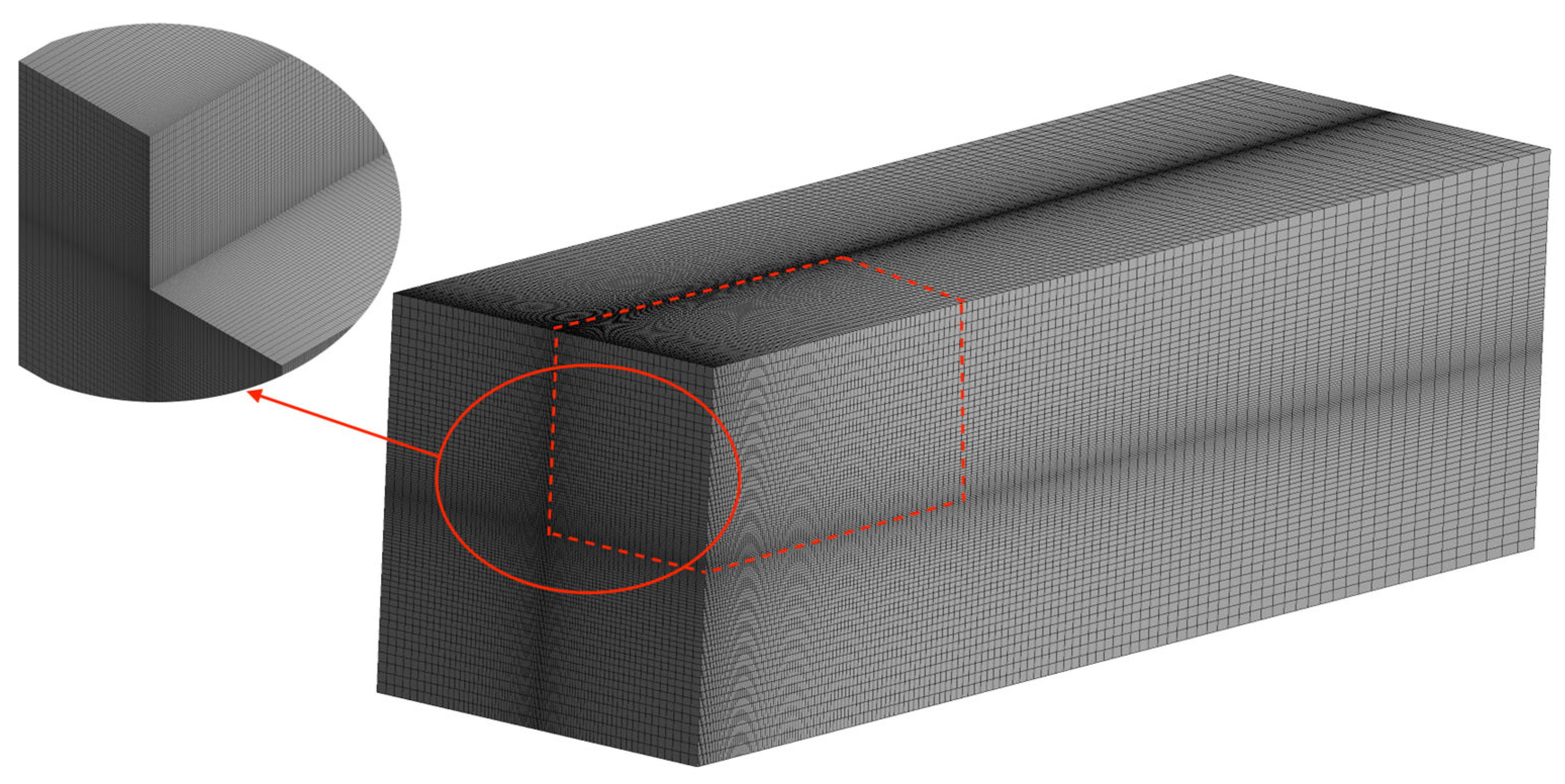
For M4, the grid generation process yielded a total of 1,083,750 hexahedral cells (Figure 3). These cells were distributed with 150 elements on the longer sides and 85 elements on the shorter sides, with appropriate bias factors to achieve the required local refinement around the injector and wall boundary layers. The minimum and maximum cell volumes are 3.4 × 10⁻⁸ m3 and 4.6 × 10⁻⁶ m3, respectively. The meshing approach results in a y+ value between 35 and 150 for the case with an inlet air velocity of 3 m/s. The mesh is also sufficiently fine near the centre of the domain, which is important since the initial droplet behaviour greatly affects the accuracy of the subsequent simulation.

3. Results and Discussion

3.1. Validation and Initial Analysis

Sureshkumar et al. [16] have generated extensive experimental data on evaporative sprays, which are used for our model validation. In these wind tunnel experiments, the inlet air and water temperatures are 39.2 °C and 35.2 °C, respectively. The other input parameters for the spray nozzle are available in Table 4. The same conditions were employed in our CFD model.
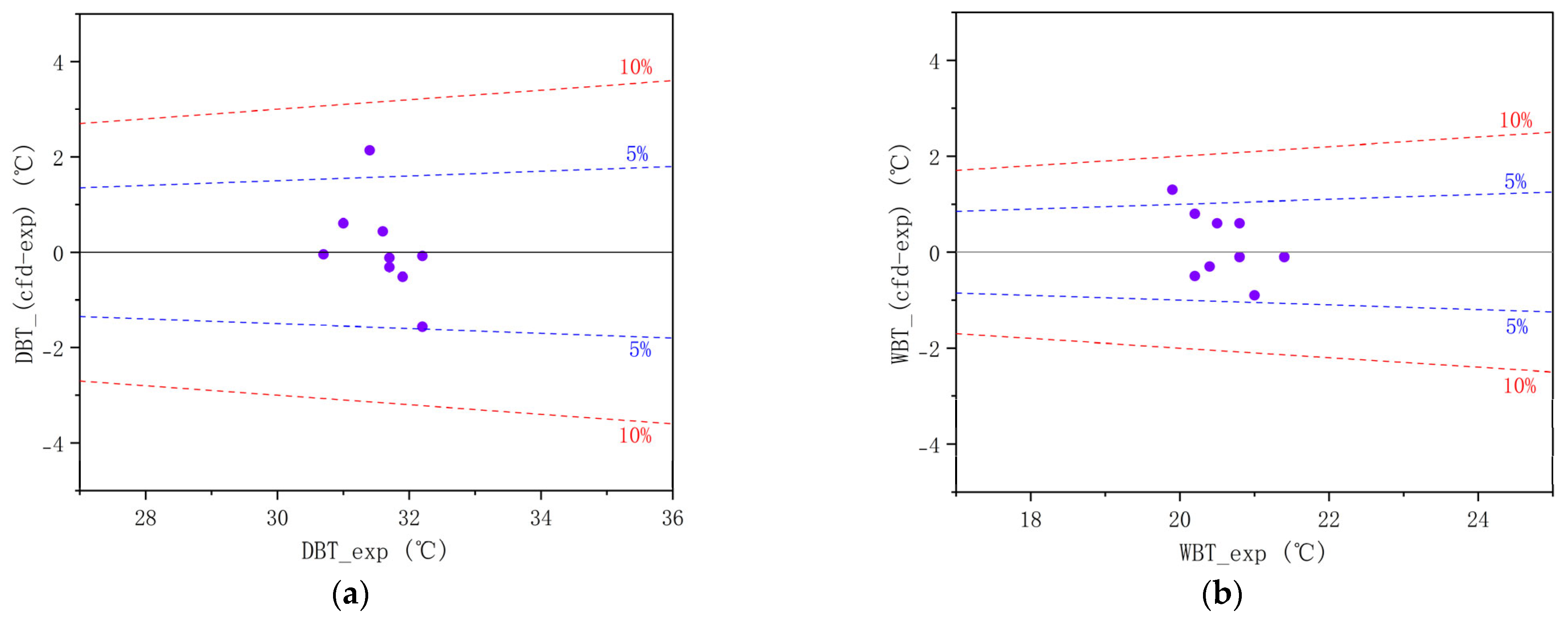
Figure 4a,b present a comparison between the simulations and wind tunnel experimental results at nine measurement points. This comparison was performed for dry bulb temperature (DBT) and wet bulb temperature (WBT) simulation results against the available experimental data (Exp. [16]). The data demonstrate a high degree of correlation between the current simulation results and the experimental outcomes, with eight points exhibiting a discrepancy of less than 5% and one point falling within the 10% range in both DBT and WBT.
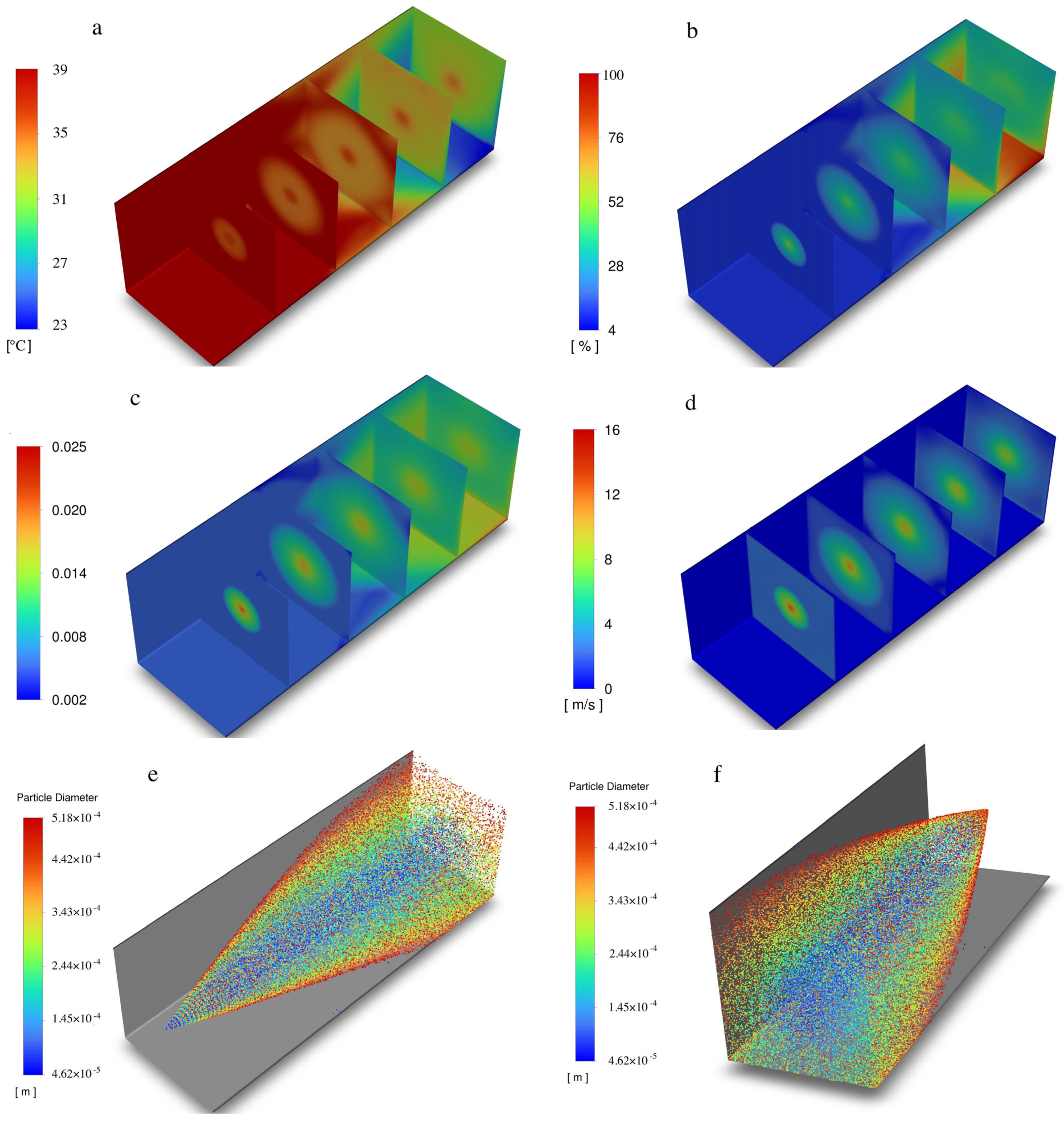
Figure 5a,b illustrate the temperature and relative humidity contours across the domain during the evaporation process. It can be observed that as evaporation occurs, there is a decline in temperature and an increase in relative humidity. Meanwhile, the mass fraction of H₂O is observed to increase (Figure 5c) due to the rise in vapour concentration, while the velocity is seen to decline (Figure 5d). Figure 5e,f depict the droplet diameter distribution, which reveals that the minimum diameter is less than 74 μm. As this study did not incorporate droplet collision and secondary breakup, the reduction in diameter is primarily attributed to evaporation. Additionally, the primary cooling region can be identified through the droplet size distribution.

3.2. Impact of Different Geographical Conditions

The evaporation system performance is subject to variation depending on geographical conditions. Previous studies have indicated that temperature drops are more pronounced in hot, dry environments [25]. However, previous studies have not examined the temperature and humidity range in sufficient detail [16,24,25]. This section illustrates the temperature drop at the inlet in the temperature range of 10 °C to 50 °C and the relative humidity in the range of 10% to 90%. The droplet size distribution range used here is 74 µm to 518 µm, with a mean diameter of 369 µm.
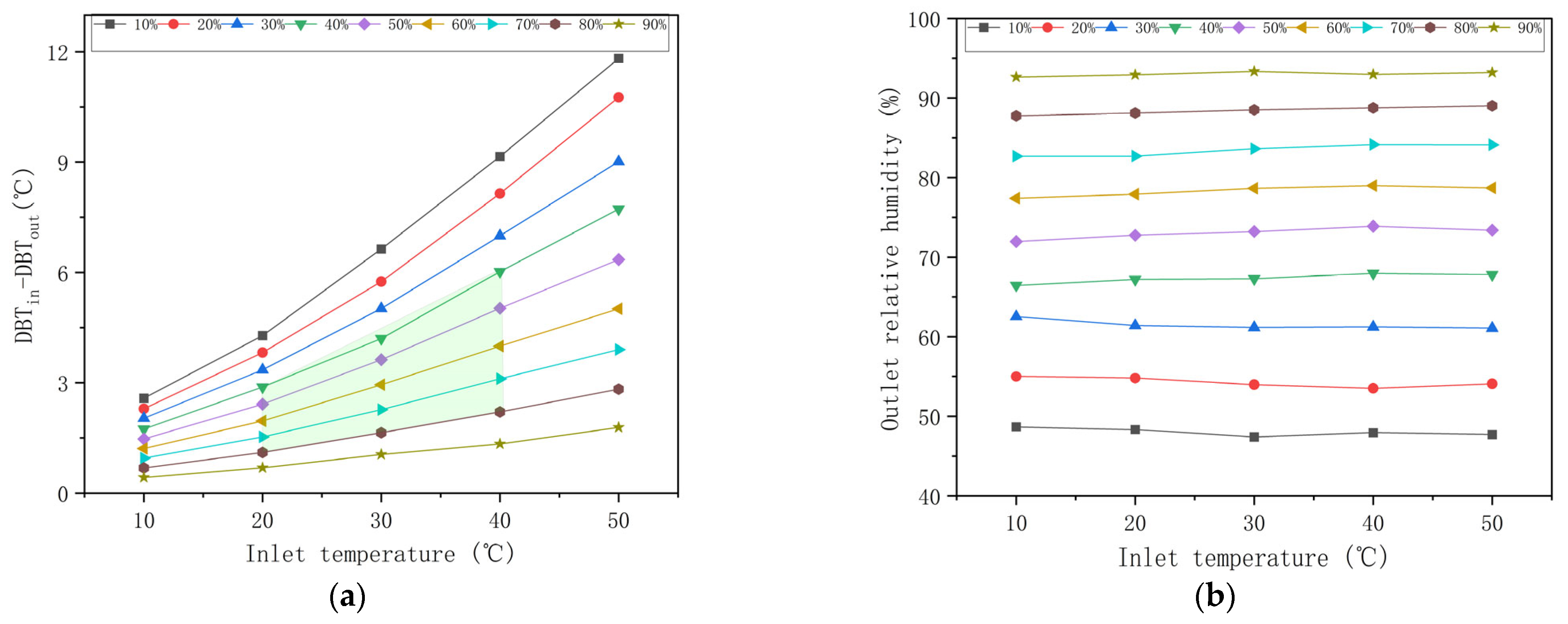
Figure 6a,b show the inlet-to-outlet bulk temperature difference and outlet relative humidity for different inlet temperature and humidity conditions. In the region of high temperature and low humidity, the temperature drop is higher. At 50 °C with 10% humidity, the temperature drop is approximately 12 °C. Conversely, at 10 °C with 90% humidity, the temperature drop is less than 1 °C.
Accordingly, Figure 6a,b serve as a valuable point of reference for the analysis of evaporation systems in diverse geographical contexts. However, it is important to note that regions experiencing extreme dryness and high temperatures often face significant water scarcity challenges. It is also notable that this range does not represent the majority of climatic conditions across the planet, as illustrated by global temperature and humidity [41]. The green region in Figure 6a represents the most common temperature and relative humidity worldwide. Consequently, in most circumstances, this evaporation system can facilitate a 1.5 to 6 °C reduction in temperature for a given average droplet size of 369 µm. Figure 6b illustrates that the outlet humidity is independent of the initial temperature, which shows the saturation limit for the evaporation system under these conditions. The change between the inlet and outlet humidity levels decreases as the initial humidity level increases. This suggests that the evaporation rate decreases as the relative humidity level rises. The range of the temperature drop can be enhanced by optimizing the spray characteristics, such as reducing the droplet size and mass flow rate. To investigate the influence of the spray characteristics for a given geographical location, the conditions in Dublin, Ireland, were employed.

3.3. Impact of Mass Flow Rate

This section employs the summer average temperature and humidity in Dublin, which are 19 °C and 68%, respectively. As illustrated by the psychometric chart, the theoretical maximum temperature drop, which corresponds to a relative humidity increase of 100%, is approximately 3 °C.
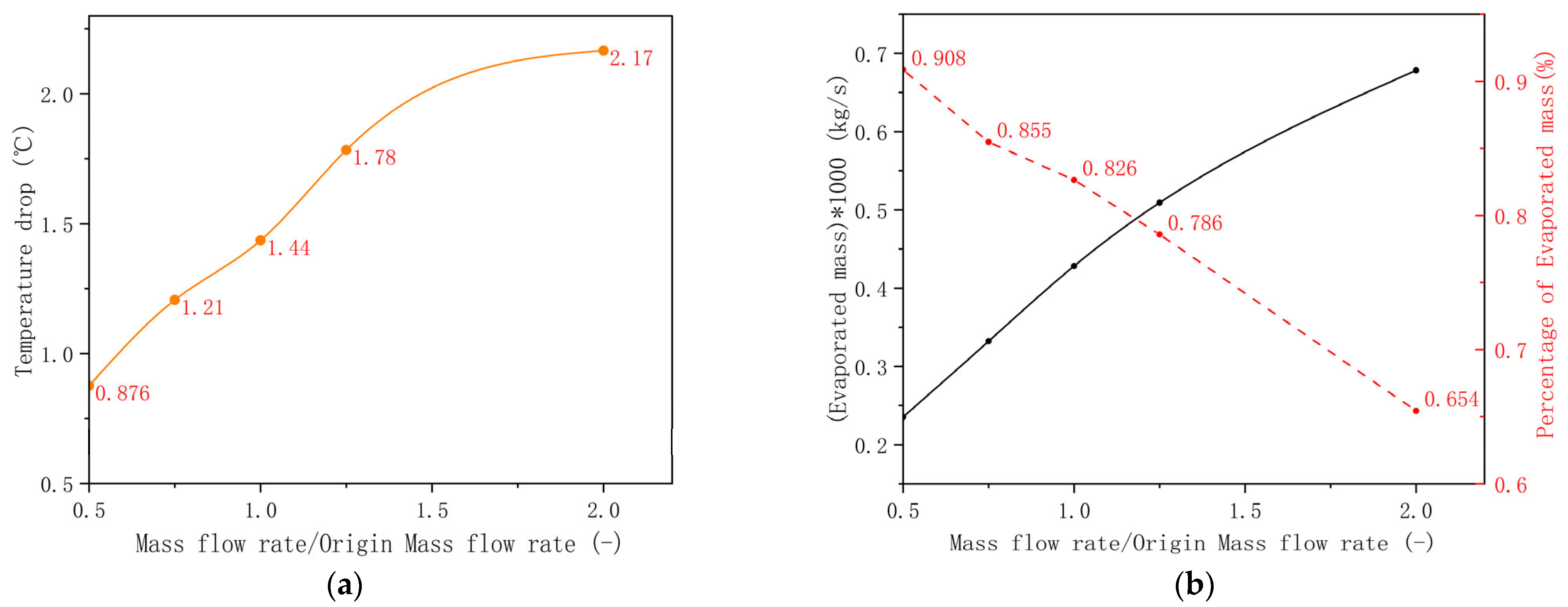
Figure 7a depicts the temperature difference between the inlet and outlet (∆T) for five distinct mass flow rates, which are 0.5 m ˙ , 0.75 m ˙ , m ˙ , 1.25 m ˙ , and 2 m ˙ , where m ˙ is the original mass flow rate given in Table 4. Figure 7b illustrates the evaporation rate and the percentage of evaporated mass.
The results demonstrate that if the water mass flow rate increases within this range, the temperature difference between the inlet and outlet conditions also increases and vice-versa. As the mass flow rate increases from m ˙ to 2 m ˙ , ∆T increases by 50.8%. Additionally, temperature drop fluctuations are associated with the evaporation rate. An elevated evaporation rate results in a greater reduction in temperature. Conversely, the percentage of evaporated mass is observed to decrease in conjunction with an increase in mass flow, from 0.5 m ˙ to 2 m ˙ , as shown in Figure 7b. This is accompanied by an 188% increase in evaporation rate and a 28% reduction in the percentage of evaporated mass. This observation is of critical importance for the optimization of the mass flow rate in an evaporation system. The optimal system should allow a reduction in the overall water consumption rate with an increase in the evaporation percentage by achieving a desired temperature drop. This can be achieved in two ways: (1) by increasing the length of the domain to allow the system to reach its saturation limit, or (2) by reducing the average droplet size and water mass flow rate to increase evaporation percentage. Both possibilities are explored below.

3.4. Impact of the Length of the Domain

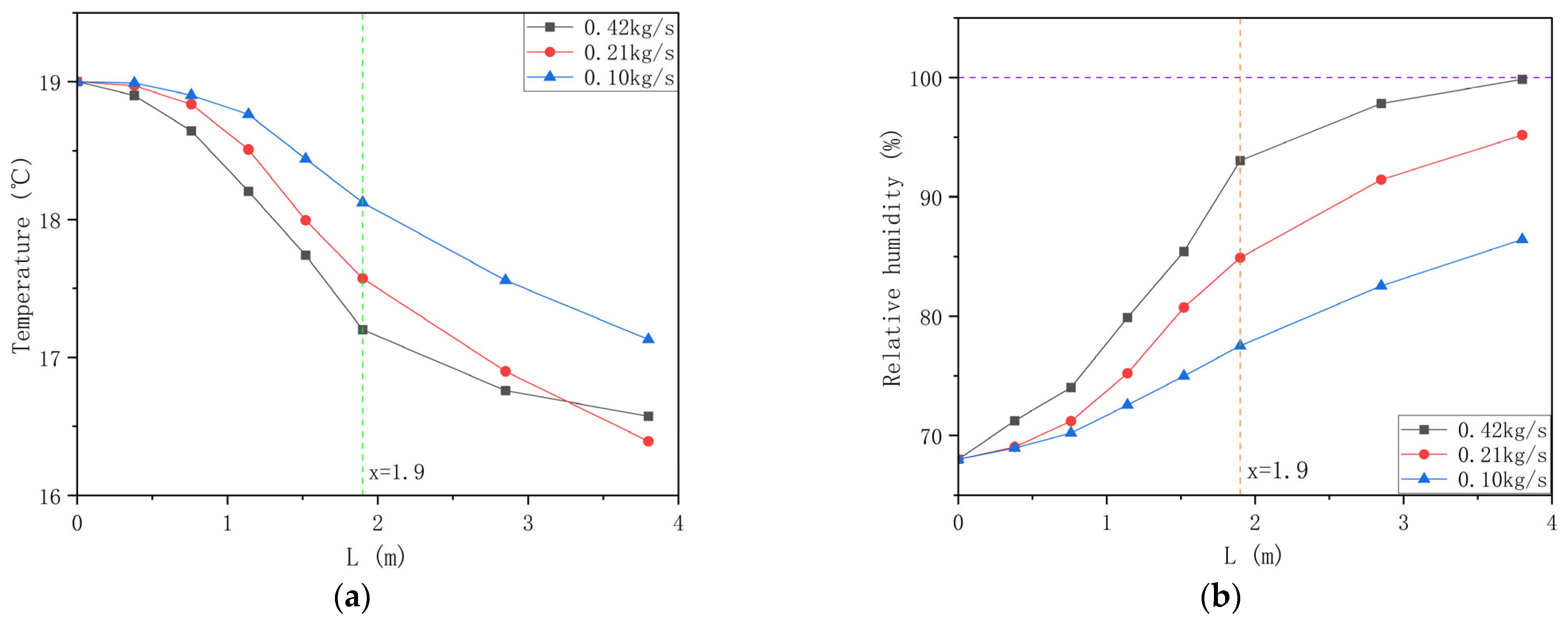
The temperature and relative humidity variations across the domain are illustrated in Figure 8a,b. In the current situation, the length of the domain was doubled from its original value (1.9 m to 3.8 m) without changing any other parameters except the mass flow rate. It demonstrates that at a domain length of L = 1.9 m, the temperature decline is more pronounced and rapid when the mass flow rate is elevated. However, when the domain is extended to 3.8 m, the highest mass flow rate case gives rise to the highest relative humidity. When the relative humidity exceeds 95%, the evaporation process is nearly halted for the highest mass flow rate. The other two points show continuous improvement with an increase in the domain length since the saturation limit is still not reached. Therefore, for a specified temperature reduction, an expansion of the domain can diminish the mass flow rate and subsequently decrease the water consumption.
It is important to note that for doubling the mass flow rate (2 m ˙ ), after a certain domain length, the temperature drop shows a crossover with the m ˙ case, even though the relative humidity is higher in comparison to the original case. The higher water mass flow rate leads to a higher evaporation rate but also increases the mass flow rate of the mixture. Since the total mass that needs to be cooled down increases, this leads to a smaller temperature drop in comparison to the original case. Hence, there will always be an upper limit on the water mass flow rate for which the evaporative cooling will perform optimally. The next section explores the droplet size and mass flow rate on evaporation system efficiency.

3.5. Average Droplet Size and Mass Flow Rate

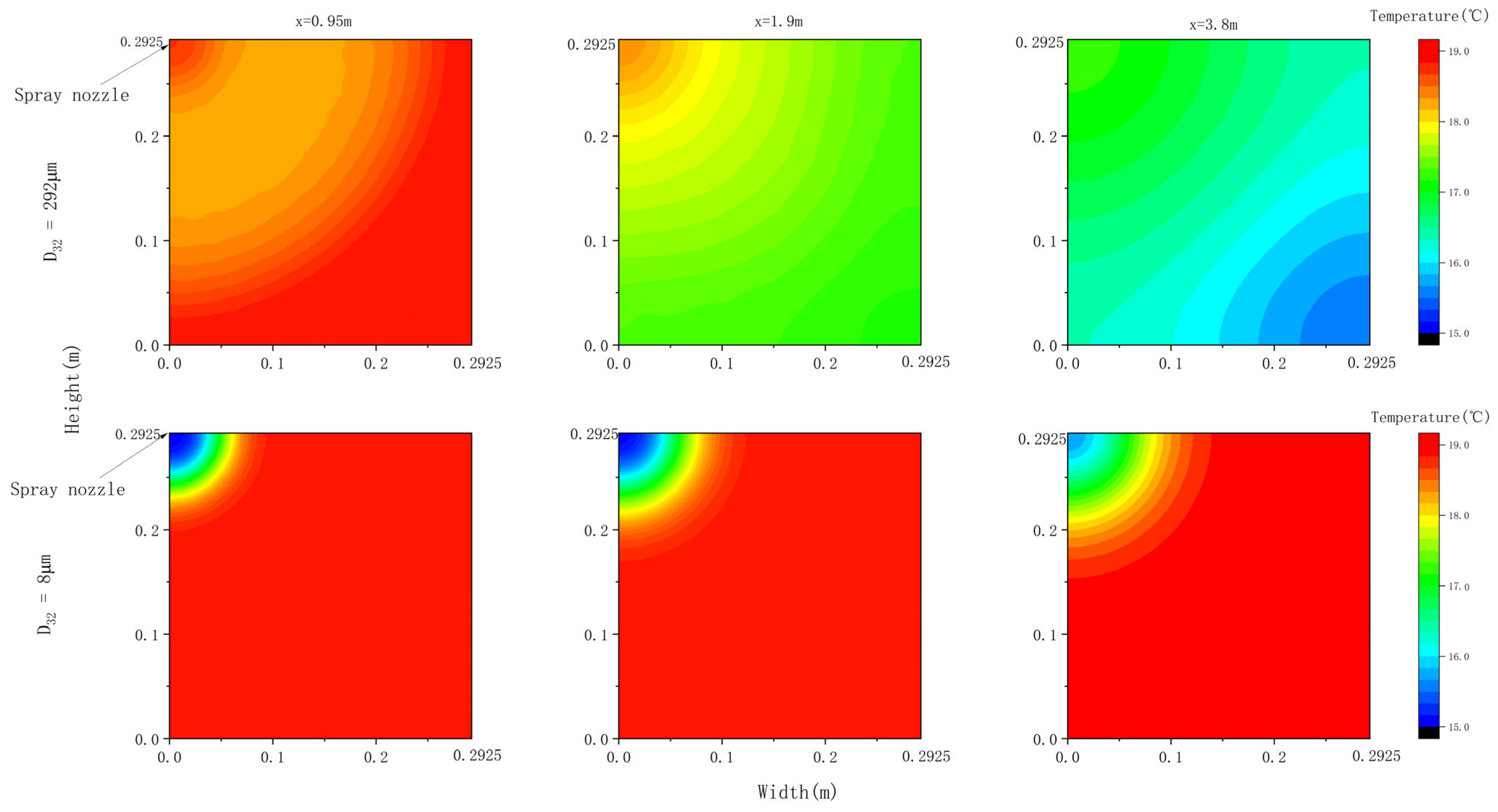
Figure 9 depicts the temperature contour plots for the two extreme cases of Sauter mean diameter and water mass flowrate (D32 = 292 μ m , m ˙ = 0.21 kg/s and D32 = 8 μ m , m   ˙ = 0.0001 kg/s). It is evident that under these two conditions, the system exhibits disparate behaviours. For the case D32 = 292 μ m , m ˙   = 0.21 kg/s, the temperature gap is considerable along the domain, whereas the centre region is distinguished by a higher temperature. However, a reduction in droplet size and mass flowrate (D32 = 8 μ m , m   ˙ = 0.0001 kg/s) resulted in the airflow becoming dominant, with the droplets’ evaporation concentrating in the centre region. Concurrently, there was an increase in temperature reduction in the centre region, with the temperature along the domain changing slightly in the centre region. Therefore, when the droplet size is small, the cooling effect is concentrated in the central region, with the length of the domain having a minimal impact on the centre region. This suggests that the length of the domain can be reduced with minimal effect on the cooling efficiency of the centre region. To further explore this, an intermediate diameter of D32 = 15 μ m was analysed with an increasing mass flow rate.
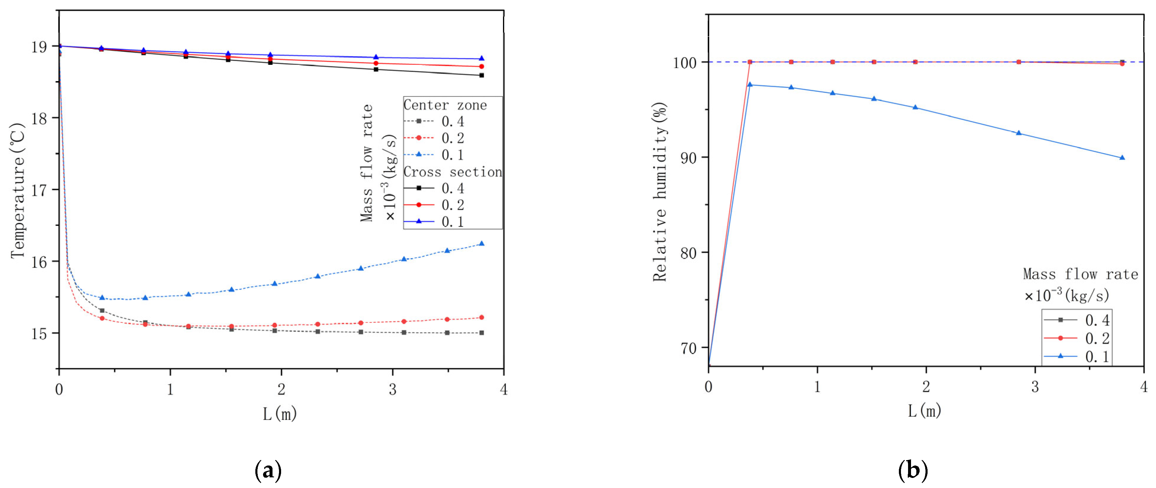
Figure 10a illustrates the temperature change along the domain length with an increasing mass flow rate for D32 = 15 μ m . The solid line represents the average temperature of the cross-section, while the dotted line depicts the temperature of the centre region along the domain. The overall cross-sectional temperature change is relatively minor for all three mass flow rates used. This is because a very small water flow rate was used in these simulations. This leads to the cooling region being primarily concentrated in the centre. This condition leads to a high evaporation percentage but overall lower water mass flowrate evaporation (refer to previous Section 3.3 for details). For the higher mass flowrate points ( m ˙ = 0.2 × 10⁻³ kg/s and 0.4 × 10⁻³ kg/s), the temperature of the centre region became almost constant after a short distance due to the high evaporation rate and the attainment of 100% relative humidity, as illustrated in Figure 10b. However, an increase in temperature is observed when m ˙ = 0.1 × 10⁻³ kg/s, accompanied by a subsequent decrease in relative humidity. This is attributed to the low mass flow rate, which results in the evaporation process occurring within a short distance. For the smallest mass flow rate case, m ˙ = 0.1 × 10⁻³ kg/s, the overall water mass flow rate is not sufficient to saturate the humid air. Hence, we observe an increase in the centreline temperature and a drop in relative humidity after a domain length of 0.7 m. To summarise, to achieve the optimal performance for a sufficiently fine droplet size spray, an optimal water flow rate should be determined, and the results associated with this are available in the next section.

3.6. Optimization Strategy for the Injector Design

The optimization strategy aims to reduce water consumption and enhance cooling efficiency. The current simulation has an inlet Sauter mean diameter (D32) close to 300 μm, which is quite large. The results in the previous sections have shown that the evaporation percentage increases with a reduction in water mass flow rate and droplet size (refer to Section 3.3 and Section 3.5 for details). Meanwhile, reducing the droplet size increases the evaporation rate [18,25,26]. Therefore, it is possible to utilize a smaller droplet size in conjunction with a reduced mass flow rate, thus enhancing the evaporation efficiency. The optimization strategy involves the following steps:
  • Fixing the upper limit of the droplet diameter and reducing the water mass flow rate in a geometric progression with ratio ½, and obtaining a relative humidity value close to 100%.
  • Reducing the droplet diameter in a geometric progression with ratio ½, repeating Step 1 until the 100% relative humidity point is achieved.
Following the above optimization strategy, six different D32 values were investigated, starting from D32 = 292 μ m and m ˙ = 0.4 2 kg/s for a domain length of 3.8 m.
According to the definition of the coefficient of performance (COP), this metric relates the useful output power and the required input power, thereby reflecting the efficiency of the evaporation system (refer to Section 2.5 for details). A list of the D32 values and fifteen different mass flow rates (from D1–D15) along with the relevant calculated power values is shown in Table 5.
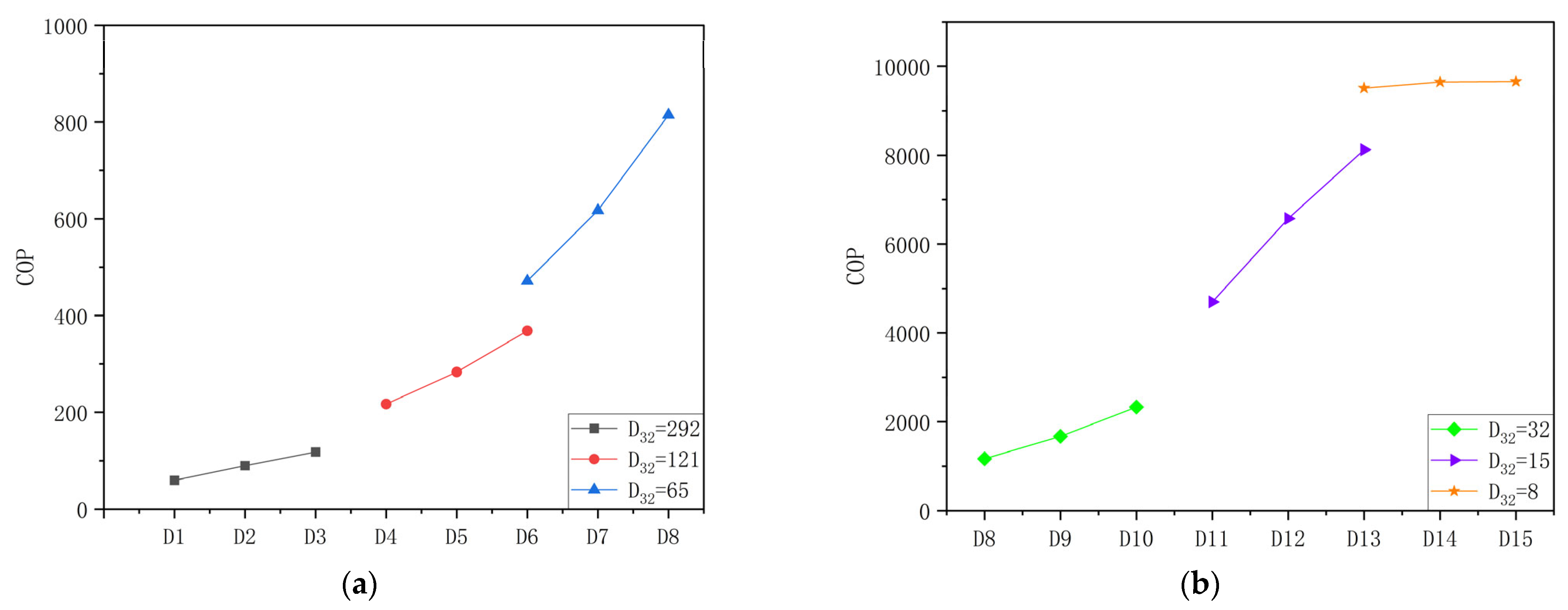
The results demonstrate that Q decreases when the Sauter mean diameter D32 and mass flow rates are reduced. This is attributable to a reduction in the quantity of evaporated mass. However, the pumping power also exhibits a notable decline. Figure 11a,b depict the COP as a function of D32 and mass flow rates. As the mass flow rate and droplet diameter decrease, the COP increases significantly. This indicates that the use of fine droplets and a low mass flow rate can enhance the efficiency of evaporation. The COP shows saturation with water mass flow rate for a droplet size of 8 μ m , which is the ideal droplet size for the best performance.
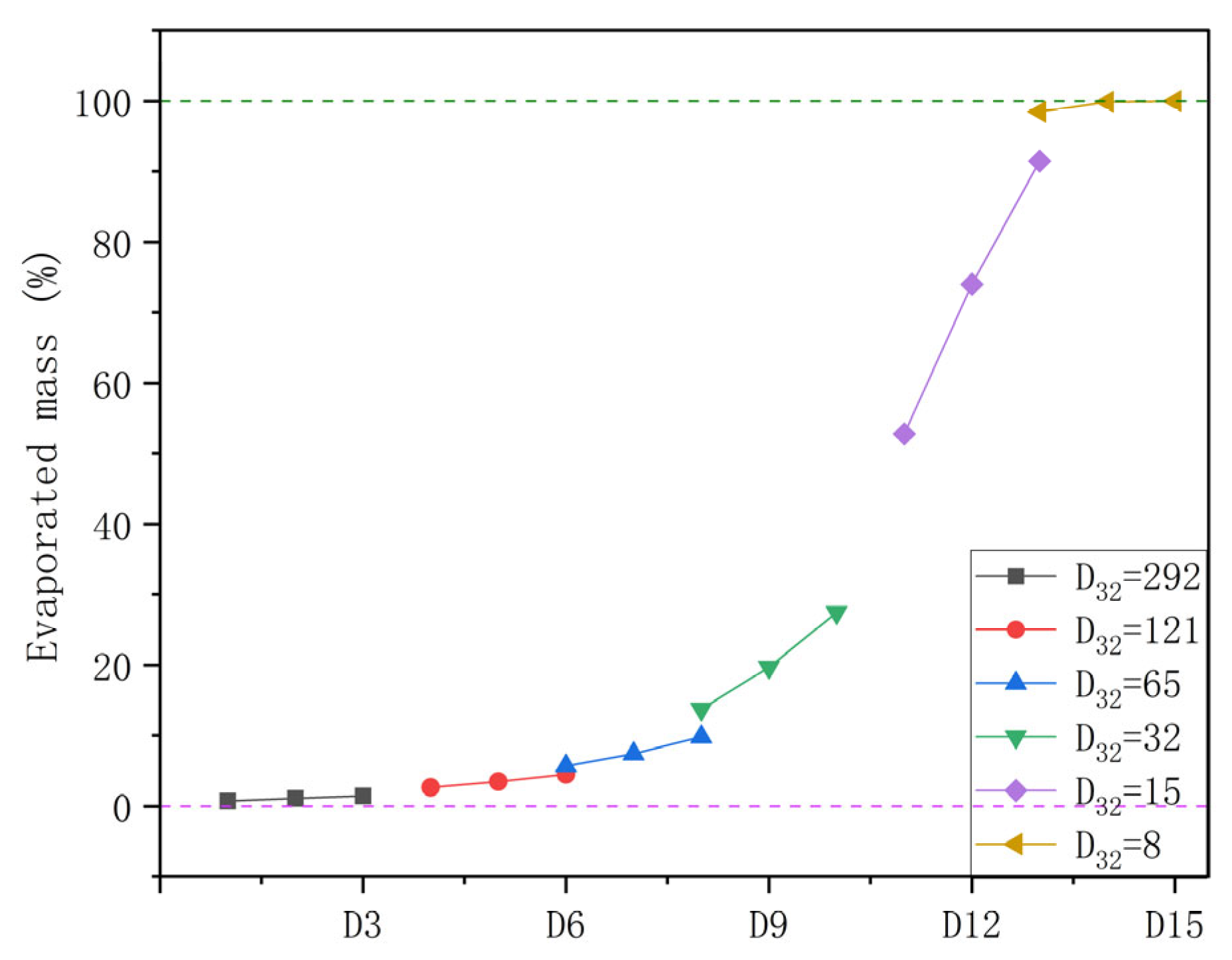
As illustrated in Figure 12, a reduction in both the D32 and mass flow rate results in an increased evaporation percentage. It is noteworthy that the evaporation rate increases significantly when the D32 is below 20 μm, exceeding 50%. Moreover, when the D32 is 8 μm, the evaporation rate approaches 100%. Thus, when the D32 is below 10 μm, the coefficient of performance (COP) exhibits only slight variation. Meanwhile, the COP is more than ten times higher when the D32 is 8 μm than when it is over 50 μm. In comparison, the water consumption exhibited a notable decline when D32 = 8 μm was employed. The total water consumption is only 3% of the original design. However, an arrangement of 30 nozzles needs to be deployed to achieve the same amount of cooling as that of the original design. The number of nozzles can be reduced if we can achieve close to a 100% evaporation rate by further increasing the mass flow rate.
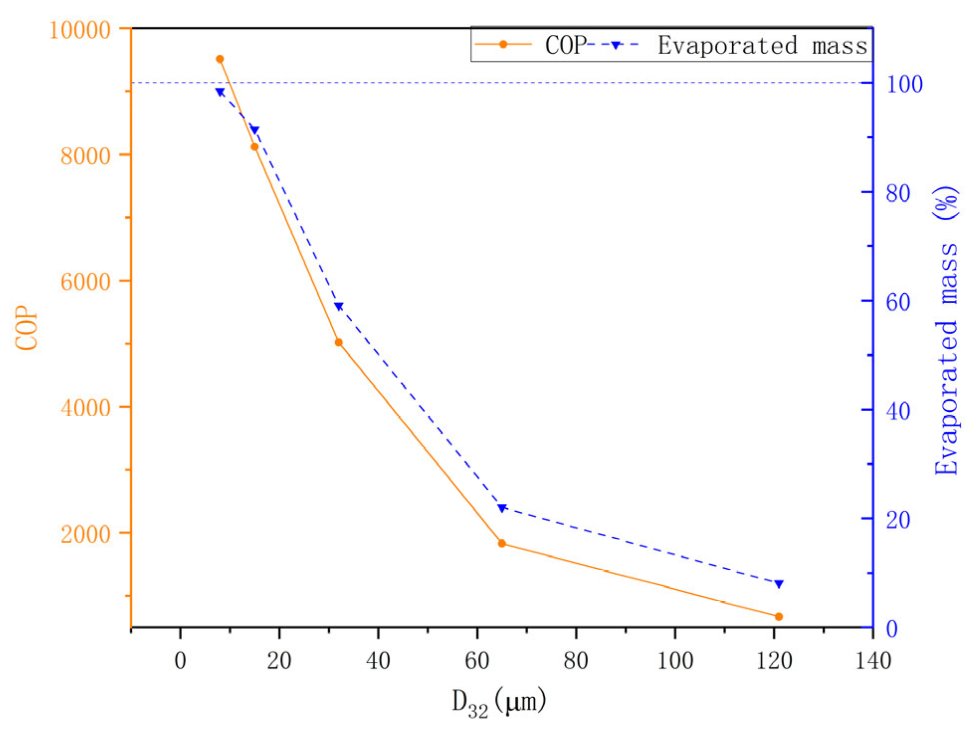
Figure 13 examined the COP and evaporation rate under different droplet sizes with m ˙   = 0.0001 kg/s. It was observed that when the mass flow rate was held constant, the evaporation rate and COP improved with a reduction in the droplet size. These results show that is possible to achieve 100% evaporation with sprays of droplet diameter (D32) in the range of 8 to 15 μm. Any further increase in the droplet diameter results in a significant reduction in the evaporation percentage and COP. The evaporation percentage drops to less than 10% for D32 larger than 120 μm.

4. Limitations

The present work introduces a novel approach to examining the performance of the evaporation system in a numerical method. However, the modelling part contains some limitations. This model did not account for droplet-to-droplet interactions or droplet coalescence. The spray was assumed to be dilute, and secondary breakup was not considered. Meanwhile, the droplet distribution is regarded as an optimal Rosin–Rammler distribution, exhibiting a degree of divergence when compared to the actual spray. The DPM wall model assumes that, following droplet impingement, no further normal momentum is imparted to the droplets. Thus, a film of water will form on the wall. However, when the droplet impinges on a solid surface, different phenomena can occur. However, these assumptions were also employed in the other published works. According to the validation results, while they may introduce some degree of error, the accuracy of the results is deemed acceptable.

5. Conclusions

In this paper, a 3-D numerical model for evaporating water spray was developed and validated against the available experimental measurements. The study was performed using different water mass flow rates, domain sizes and droplet sizes, and different geographical conditions (although the focus was on the conditions for Dublin, Ireland). The following is the list of conclusions drawn from this study:
(1)
The temperature and humidity of the air have a big influence on the evaporation system. Regions with high temperatures and low humidity experience the greatest cooling effect, with temperature drops of up to 12 °C at 50 °C and 10% humidity. Most regions fall within moderate temperature and humidity ranges, where evaporation systems typically reduce temperatures by 1.5 to 6 °C for an average Sauter mean diameter (SMD) of 292 μm.
(2)
Increasing mass flow rates in evaporation systems significantly enhances the temperature drop, with a 50.8% rise in ΔT as the flow rate increases from to 2. However, this is accompanied by a decrease in the percentage of evaporated mass reducing the overall system performance (COP) in terms of water consumption.
(3)
Extending the domain length significantly enhances cooling efficiency, with the temperature disparity between the inlet and outlet increasing by 85.7% and relative humidity rising by 61%. An increase in the mass flow rate results in a more rapid decline in temperature. However, beyond a certain distance, the evaporation rate declines due to the air becoming saturated, thereby limiting the evaporation process.
(4)
Larger droplets (D32 = 292 μm, = 0.21 kg/s) result in a notable reduction in temperature across the domain, with higher temperatures observed in the central region. In contrast, smaller droplets (D32 = 8 μm, = 0.0001 kg/s) exert a dominant influence on the airflow, resulting in the concentration of cooling in the centre region with minimal temperature change along the domain. Therefore, to achieve the same amount of cooling, a multi-nozzle configuration is required.
(5)
Reducing droplet size also enhances the evaporation rate, with smaller droplets (D32 < 20 μm) exceeding 50% evaporation, and at 8 μm, achieving 100% evaporation. Additionally, smaller droplet sizes reduce water consumption, with D32 = 15 μm using just 3% of the original water volume. The analysis of the coefficient of performance (COP) reveals that smaller droplets and lower mass flow rates result in higher COP, as the efficiency of the whole system is improved.
(6)
It was demonstrated that both the evaporation rate and the coefficient of performance (COP) decrease as the size of the droplets increases. This reduction is attributable to the fact that larger droplet sizes reduce the overall surface area available for evaporation under a given water mass flow rate.

Author Contributions

Conceptualization, S.M.A., N.G. and T.P.; methodology, S.M.A. and N.G.; software, N.G. and S.M.A.; validation, N.G.; formal analysis, N.G. and S.M.A.; investigation, S.M.A. and N.G.; resources, T.P. and S.M.A.; data curation, N.G.; writing—original draft preparation, N.G. and S.M.A.; writing—review and editing, S.M.A. and T.P.; visualization, N.G.; supervision, S.M.A. and T.P.; project administration, T.P. and S.M.A. All authors have read and agreed to the published version of the manuscript.

Funding

This research received no external funding.

Data Availability Statement

The data presented in this study will be made available upon request from the corresponding author.

Acknowledgments

The authors would like to thank the Department of Mechanical, Manufacturing and Biomedical Engineering, Trinity College Dublin, Dublin, Ireland for providing the computational resources required for the present work.

Conflicts of Interest

The authors declare no conflicts of interest.

Abbreviations

The following abbreviations are used in this manuscript:
ASurface aream2
BmSpalding number-
C μ Turbulence viscosity coefficient-
C d Drag coefficient-
CvNozzle velocity coefficient-
C 1 ϵ , C 2 ϵ Empirical coefficient-
c p Heat capacity J / kg · K
DDiameter Μ m
D ¯ Mean diameter Μ m
Di,mDiffusion coefficientm2/s
GGravity termN
gGravitational accelerationm/s2
hEnthalpyJ/kg
ITurbulent intensity%
kTurbulent kinetic energym2/s2
kcMass transfer coefficient-
LHVLatent heat of water vaporizationkJ/kg
lTurbulent length scaleM
mMass Kg
m ˙ Mass flow ratekg/s
NuNusselt number-
PPressurePa
PkProduction of turbulent kinetic energykg/m·s3
PrPrandtl number-
QEnthalpy changeW
ReRelative Reynolds number-
S e Source term of energyW/m3
SmSource term of masskg/m3·s
S m o Source term of momentumkg/(m2·s2)
S i Source term for species transportkg/m3·s
ScSchmidt number-
ShSherwood number-
TTemperature°C
u i , u j Mean velocity vectorm/s
U0Initial nozzle velocitym/s
V T ˙ Volumetric flow ratem3/s
vvelocitym/s
Y i , ¯ Y j ¯ Mass fraction of species-
Y i , s Vapour masa fraction at the surface -
Y i , Vapour masa fraction in the air-
Greek symbols
α N Half cone angle°
δ i j Kronecker delta-
ϵ dissipation ratem3/s3
λ Mixture thermal conductivity W / ( m · K )
μ Dynamic viscosity kg / m · s
μ t Turbulent viscosity kg / m · s
ρ Densitykg/m3
ϵ Turbulent dissipation ratem2/s3
Dissipation rateW/m3
σ ϵ Turbulent Prandtl number for ϵ -
ω Mass fraction-
γ Droplet surface tensionN/m
χ Specific humidity-
Subscripts
aAir
COPCoefficient of performance
dDroplet
DBTDry bulb temperature
i,jCartesian coordinate directions
SEPSurface energy per unit
turTurbulent
WBTWet bulb temperature

Appendix A. Derivation of Surface Energy Power (SEP)

The surface energy ( S E D ) of a single droplet of diameter D is given by Equation (A1) below.
S E D = γ . A D
The droplet formation rate ( N ˙ D ) for a diameter D is given by:
N ˙ D = f 3 D . V ˙ T . d D V D
The contribution to the surface energy power (SEP) for droplets of diameter D is given by:
d E ˙ D = γ . A D . N ˙ D = 6 γ . V ˙ T f 3 D D   d D
Therefore, the total surface energy power (SEP) for a spray with a range of diameters can be found as:
S E P = d E ˙ D = 6 γ . V ˙ T f 3 D D   d D
MATLAB Code for Calculating SEP
gamma = 0.072; % Surface tension (N/m)
V_dot_total = 1.0018E-07; % volumetric flow rate (m3/s)
n = 3.67; % Spread parameter
D_bar = 0.000150; % Mean diameter (m)
d_min = 0.000037; % Min. diameter (m)
d_max = 0.000259; % Max. diameter (m)
% Define the function f_3(D)
fv = @(d) (n / D_bar) * (d / D_bar).^(n - 1) .* exp(-(d / D_bar).^n);
% Integral (1/m)
integral_value = integral(@(d) fv(d) ./ d, d_min, d_max);
% Total energy dissipation rate (W)
E_dot_total = 6 * gamma * V_dot_total * integral_value;
% Display the result
disp(['Total Energy Dissipation Rate (E_dot_total): ', num2str(E_dot_total)]);

Appendix B. Sample Calculation for COP

For instance, take the case D9 (see Table 5). The water mass flow rate ( m ˙ l ) from the nozzle is 1.6 × 10 3 kg/s. The pressure drop ( Δ P ) across the nozzle is 3 bar. The evaporated water mass flow rate percentage ( ε ) is 19.67%. The latent heat of vaporization ( L H V ) of water and surface tension ( γ ) are 2446.3 kJ/kg and 0.072 N/m respectively. The Sauter mean diameter (D32) is 32 μ m with spray characteristics given by Rosen-Rambler distribution using Equation (19).
The calculated useful heat load (Q) value is:
Q = m ˙ l . α . L H V = 770   W
The calculated pump power ( P p u m p ) value is:
P p u m p = m ˙ l . Δ P = 0.48   W
The calculated surface energy power (SEP) value is:
S E P = 6 γ . V ˙ T f 3 D D   d D = 0.0199   W
The calculated coefficient of performance (COP) value is:
C O P = Q P p u m p S E P = 1673.55

References

  1. Cai, S.; Gou, Z. Towards Energy-Efficient Data Centers: A Comprehensive Review of Passive and Active Cooling Strategies. Energy Built Environ. 2024; in press. [Google Scholar] [CrossRef]
  2. Central Statistics Office. Key Findings. Data Centres Metered Electricity Consumption 2022. Available online: https://www.cso.ie/en/releasesandpublications/ep/p-dcmec/datacentresmeteredelectricityconsumption2022/keyfindings/ (accessed on 3 August 2024).
  3. IEA. International Energy Agency. Available online: https://www.iea.org (accessed on 3 August 2024).
  4. Du, S.; Zhang, Q.; Zou, S.; Meng, F.; Liu, L. Simulation Analysis on Energy Consumption and Economy of CPU Cooling System Based on Loop Heat Pipe for Data Center. Therm. Sci. Eng. Prog. 2023, 45, 102115. [Google Scholar] [CrossRef]
  5. Zhang, Z.; Wang, X.; Yan, Y. A Review of the State-of-the-Art in Electronic Cooling. E-Prime-Adv. Electr. Eng. Electron. Energy 2021, 1, 100009. [Google Scholar] [CrossRef]
  6. Kapilan, N.; Isloor, A.M.; Karinka, S. A Comprehensive Review on Evaporative Cooling Systems. Results Eng. 2023, 18, 101059. [Google Scholar] [CrossRef]
  7. McCay, O.; Nimmagadda, R.; Ali, S.M.; Persoons, T. A Parametric Design Study of Natural-Convection-Cooled Heat Sinks. Fluids 2023, 8, 234. [Google Scholar] [CrossRef]
  8. Zhang, Q.; Meng, Z.; Hong, X.; Zhan, Y.; Liu, J.; Dong, J.; Bai, T.; Niu, J.; Deen, M.J. A Survey on Data Center Cooling Systems: Technology, Power Consumption Modeling and Control Strategy Optimization. J. Syst. Archit. 2021, 119, 102253. [Google Scholar] [CrossRef]
  9. Zhang, H.; Shao, S.; Xu, H.; Zou, H.; Tian, C. Free Cooling of Data Centers: A Review. Renew. Sustain. Energy Rev. 2014, 35, 171–182. [Google Scholar] [CrossRef]
  10. Hnayno, M.; Chehade, A.; Klaba, H.; Polidori, G.; Maalouf, C. Experimental Investigation of a Data-Centre Cooling System Using a New Single-Phase Immersion/Liquid Technique. Case Stud. Therm. Eng. 2023, 45, 102925. [Google Scholar] [CrossRef]
  11. Bapu, B.R.R.; Kayalvizhi, S.; Murugavalli, S. Two Phase Cooling with Nano-Fluid for Highly Dense Electronic Systems-on-Chip—A Pilot Study. Microelectron. Reliab. 2020, 108, 113640. [Google Scholar] [CrossRef]
  12. Pearlmutter, D.; Erell, E.; Etzion, Y.; Meir, I.A.; Di, H. Refining the Use of Evaporation in an Experimental Down-Draft Cool Tower. Energy Build. 1996, 23, 191–197. [Google Scholar] [CrossRef]
  13. Shehabi, A.; Ganguly, S.; Gundel, L.A.; Horvath, A.; Kirchstetter, T.W.; Lunden, M.M.; Tschudi, W.; Gadgil, A.J.; Nazaroff, W.W. Can Combining Economizers with Improved Filtration Save Energy and Protect Equipment in Data Centers? Build. Environ. 2010, 45, 718–726. [Google Scholar] [CrossRef]
  14. Shehabi, A.; Horvath, A.; Tschudi, W.; Gadgil, A.J.; Nazaroff, W.W. Particle Concentrations in Data Centers. Atmos. Environ. 2008, 42, 5978–5990. [Google Scholar] [CrossRef]
  15. Bao, L.; Wang, J.; Kang, L. The Applied Effect Analysis of Heat Exchanger Installed in a Typical Communication Base Station in Beijing of China. Energy Procedia 2012, 14, 620–625. [Google Scholar] [CrossRef]
  16. Sureshkumar, R.; Kale, S.R.; Dhar, P.L. Heat and Mass Transfer Processes between a Water Spray and Ambient Air—I. Experimental Data. Appl. Therm. Eng. 2008, 28, 349–360. [Google Scholar] [CrossRef]
  17. Shao, S.; Liu, H.; Zhang, H.; Tian, C. Experimental Investigation on a Loop Thermosyphon with Evaporative Condenser for Free Cooling of Data Centers. Energy 2019, 185, 829–836. [Google Scholar] [CrossRef]
  18. Tissot, J.; Boulet, P.; Labergue, A.; Castanet, G.; Trinquet, F.; Fournaison, L. Experimental Study on Air Cooling by Spray in the Upstream Flow of a Heat Exchanger. Int. J. Therm. Sci. 2012, 60, 23–31. [Google Scholar] [CrossRef]
  19. Kachhwaha, S.S.; Dhar, P.L.; Kale, S.R. Experimental studies and numerical simulation of evaporative cooling of air with a water spray—I. Horizontal Parallel flow. Int. J. Heat Mass Transf. 1998, 41, 447–464. [Google Scholar] [CrossRef]
  20. Kachhwaha, S.S.; Dhar, P.L.; Kale, S.R. Experimental studies and numerical simulation of evaporative cooling of air with a water spray—II. Horizontal Counter Flow. Int. J. Heat Mass Transf. 1998, 41, 465–474. [Google Scholar] [CrossRef]
  21. Mao, R.; Wu, H.; Li, C.; Zhang, Z.; Liang, X.; Zhou, J.; Chen, J. Experimental Investigation on the Application of Cold-Mist Direct Evaporative Cooling in Data Centers. Int. J. Therm. Sci. 2025, 208, 109500. [Google Scholar] [CrossRef]
  22. Zhang, Y.; Chen, Y.; Yang, H.; Zhang, H.; Leung, C.W. Experimental Performance Investigation on a Desiccant-Assisted Two-Stage Evaporative Cooling System in Hot and Humid Areas. Appl. Energy 2025, 377, 124704. [Google Scholar] [CrossRef]
  23. Zhang, Y.; Han, H.; Zhang, Y.; Li, J.; Zheng, Y.; Liu, C.; Liu, Y.; Gao, D. Experimental Study on the Performance of a Novel Data Center Air Conditioner Combining Air Cooling and Evaporative Cooling. Int. J. Refrig. 2024; in press. [Google Scholar] [CrossRef]
  24. Montazeri, H.; Blocken, B.; Hensen, J.L.M. Evaporative Cooling by Water Spray Systems: CFD Simulation, Experimental Validation and Sensitivity Analysis. Build. Environ. 2015, 83, 129–141. [Google Scholar] [CrossRef]
  25. Montazeri, H.; Blocken, B.; Hensen, J.L.M. CFD Analysis of the Impact of Physical Parameters on Evaporative Cooling by a Mist Spray System. Appl. Therm. Eng. 2015, 75, 608–622. [Google Scholar] [CrossRef]
  26. Alkhedhair, A.; Gurgenci, H.; Jahn, I.; Guan, Z.; He, S. Numerical Simulation of Water Spray for Pre-Cooling of Inlet Air in Natural Draft Dry Cooling Towers. Appl. Therm. Eng. 2013, 61, 416–424. [Google Scholar] [CrossRef]
  27. Alkhedhair, A.; Jahn, I.; Gurgenci, H.; Guan, Z.; He, S.; Lu, Y. Numerical Simulation of Water Spray in Natural Draft Dry Cooling Towers with a New Nozzle Representation Approach. Appl. Therm. Eng. 2016, 98, 924–935. [Google Scholar] [CrossRef]
  28. Raoult, F.; Lacour, S.; Carissimo, B.; Trinquet, F.; Delahaye, A.; Fournaison, L. CFD Water Spray Model Development and Physical Parameter Study on the Evaporative Cooling. Appl. Therm. Eng. 2019, 149, 960–974. [Google Scholar] [CrossRef]
  29. Sureshkumar, R.; Kale, S.R.; Dhar, P.L. Heat and Mass Transfer Processes between a Water Spray and Ambient Air—II. Simulations. Appl. Therm. Eng. 2008, 28, 361–371. [Google Scholar] [CrossRef]
  30. Tissot, J.; Boulet, P.; Trinquet, F.; Fournaison, L.; Macchi-Tejeda, H. Air Cooling by Evaporating Droplets in the Upward Flow of a Condenser. Int. J. Therm. Sci. 2011, 50, 2122–2131. [Google Scholar] [CrossRef]
  31. Peng, D.; Li, Y.; Cheng, N. Study on the Performance of Tube Evaporative Cooling Dehumidifier Based on CFD. Appl. Therm. Eng. 2024, 241, 122419. [Google Scholar] [CrossRef]
  32. Climate & Weather Averages in Dublin, Ireland. Available online: https://www.timeanddate.com/weather/ireland/dublin/climate (accessed on 21 October 2024).
  33. Li, J.; Kawano, H. Simulating Water-Drop Movement from Noncircular Sprinkler Nozzles. J. Irrig. Drain. Eng. 1995, 121, 152–158. [Google Scholar] [CrossRef]
  34. Morsi, S.A.; Alexander, A.J. An Investigation of Particle Trajectories in Two-Phase Flow Systems. J. Fluid Mech. 1972, 55, 193–208. [Google Scholar] [CrossRef]
  35. Sazhin, S.S. Advanced Models of Fuel Droplet Heating and Evaporation. Prog. Energy Combust. Sci. 2006, 32, 162–214. [Google Scholar] [CrossRef]
  36. Miller, R.S.; Harstad, K.; Bellan, J. Evaluation of equilibrium and non-equilibrium evaporation models for many-droplet gas-liquid flow simulations. Int. J. Multiph. Flow 1998, 24, 1025–1055. [Google Scholar] [CrossRef]
  37. ANSYS, version 2023. ANSYS Fluent Theory Guide. Ansys Inc.: Canonsburg, PA, USA, 2023.
  38. Babinsky, E.; Sojka, P.E. Modeling Drop Size Distributions. Prog. Energy Combust. Sci. 2002, 28, 303–329. [Google Scholar] [CrossRef]
  39. Alderliesten, M. Mean Particle Diameters. Part VII. The Rosin-Rammler Size Distribution: Physical and Mathematical Properties and Relationships to Moment-Ratio Defined Mean Particle Diameters. Part. Part. Syst. Charact. 2013, 30, 244–257. [Google Scholar] [CrossRef]
  40. Ashgriz, N. (Ed.) Handbook of Atomization and Sprays: Theory and Applications; Springer: Boston, MA, USA, 2011. [Google Scholar] [CrossRef]
  41. Center for Sustainability and the Global Environment. Average Annual Relative Humidity. Available online: https://sage.nelson.wisc.edu/data-and-models/atlas-of-the-biosphere/mapping-the-biosphere/ecosystems/average-annual-relative-humidity/ (accessed on 30 July 2024).
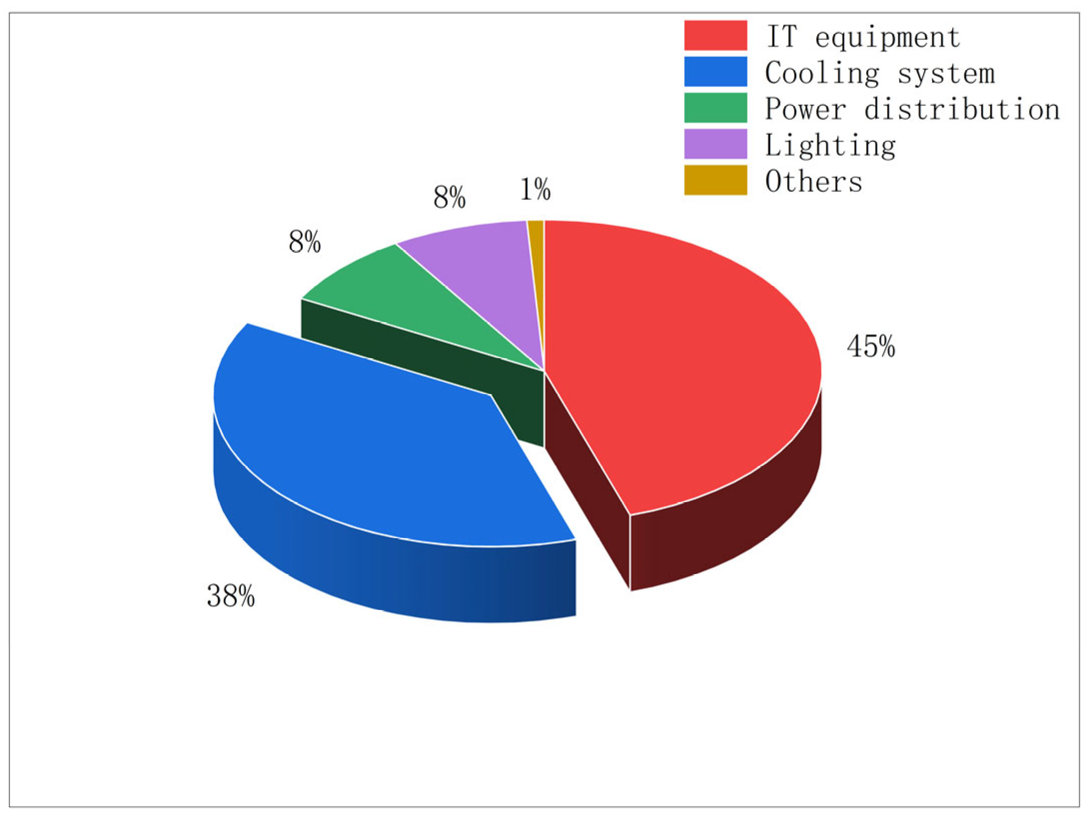
Figure 1. Energy consumption proportions of equipment in a classical data centre (adapted from [4]).
Fluids 09 00284 g001
Figure 2. Computational domain for validation.
Fluids 09 00284 g002
Figure 3. Details of the computational grid M4 (1,083,750 cells) used for further analysis.
Fluids 09 00284 g003
Figure 4. Comparison of the simulations results against the available experimental data (Exp. [16]) (a) for Dry Bulb Temperature (DBT), and (b) for Wet Bulb Temperature (WBT).
Fluids 09 00284 g004
Figure 5. Contour and particle distribution plots depicting the variation of important quantities inside the computational domain; (a) Air temperature; (b) relative humidity; (c) mass fraction of H2O; (d) velocity; (e) particle diameter seen from the inlet side; and (f) particle diameter seen from the outlet side for the validation case.
Fluids 09 00284 g005
Figure 6. (a) Temperature difference between inlet and outlet, and (b) outlet relative humidity for different inlet temperature and humidity conditions.
Fluids 09 00284 g006
Figure 7. (a) Variation of temperature difference ( T i n l e t T o u t l e t ) with increasing water mass flow rates, (b) Variation of evaporated mass flow and its percentage with increasing water mass flow rate.
Fluids 09 00284 g007
Figure 8. (a) Temperature change along the domain length, L = 3.8 m, (b) Relative humidity change along the domain length, L = 3.8 m, dashed purple line incidates the theoretical maxima for the relative humidity.
Fluids 09 00284 g008
Figure 9. Comparison of cross-sectional contour plots of air-dry bulb temperature at three axial locations.
Fluids 09 00284 g009
Figure 10. (a) Temperature variation along the domain length, and (b) Relative humidity variation along the centreline of the domain, for L = 3.8 m, D32 = 15 μ m .
Fluids 09 00284 g010
Figure 11. Coefficient of performance (COP) of different D32 and mass flow rate (D32 > 50 μ m ) (a), and (D32 < 50 μ m ) (b). See corresponding values for design points D1–D15 in Table 5.
Fluids 09 00284 g011
Figure 12. The percentage of evaporated mass in different D32 and mass flow rates. See corresponding values for design points D1–D15 in Table 5, purple and green line indicates the theoretical minima and maxima of relative humidity values.
Fluids 09 00284 g012
Figure 13. Coefficient of performance (COP) and evaporation rate under varying SMD ( D 32 ) conditions.
Fluids 09 00284 g013
Table 1. The drag coefficient for different Reynolds numbers [34].
K1K2K3Re
2400Re < 0.1
22.730.09033.690.1 < Re < 1
29.1667−3.88891.2221 < Re < 10
46.5−116.670.616710 < Re < 100
98.33−27780.3644100 < Re < 1000
148.62−4.75 × 1040.3571000 < Re < 5000
−490.5465.787 × 1050.465000 < Re < 10,000
−1662.55.4167 × 1060.519110,000 < Re < 50,000
Table 2. Summarize the configuration of the CFD solver.
Configuration
Convergence criteria (residuals)10−6
Pressure-velocity couplingPISO
Order of numerical schemesSecond order
Spatial gradient discretizationLeast squares cell based
Time step size0.001 s
Iterations per time step20
Relaxation coefficients (for pressure, density, body force, momentum, turbulent kinetic energy, turbulent dissipation rate, turbulent viscosity, H2O, energy, discrete phase source, respectively)(0.3, 1, 1, 0.7, 0.8, 0.8, 1, 1, 1, 0.9)
Table 3. Variation of mass flow-averaged outlet temperature T o u t and percentage deviation with the reduction in grid size.
Grid Number of
Elements
Average Outlet
Temperature T o u t (°C)
Relative Change in T o u t (%)Computational Time (h)
M1128,00030.6448-6
M2302,50030.69730.5512
M3612,50030.75790.3820
M41,083,75030.80770.1826
M51,800,00030.81280.01935
M62,420,00030.81370.00343
Table 4. List of main parameters for validation.
Air Water Nozzle
DBT (°C)va (m/s) ω P (bar) m ˙   (kg/s)Tw (°C)D (mm) α N (°)
39.230.005230.2135.2418
Table 5. List of values for the Sauter mean diameter D32 and mass flow rate and the resulting calculated power values, (O)—Original, (OP)—Optimized.
Design PointD32 (μm)Mass Flow Rate × 10−3 (kg/s)Evaporated Mass Flow Rate (%)SEP (W)Q (W) P p u m p (W)
D1 2924200.730.59267737.9124.8
D2 (O)2922101.100.29635572.862.4
D32921001.440.14793656.031.1
D4121522.630.18363351.215.6
D5121263.440.09182187.77.8
D6121134.470.04591422.33.9
D665135.670.07911804.63.9
D7656.47.430.03951163.11.9
D8653.29.800.0198767.30.96
D8323.213.750.03971076.40.96
D9321.619.670.0199770.00.48
D10320.827.460.0099537.40.24
D11150.452.860.0101517.20.12
D12150.274.000.0050362.00.06
D13150.191.450.0025223.70.03
D13 (OP)80.198.440.0047240.80.03
D1480.0599.870.0024122.20.015
D1580.0251000.001261.20.0075
Disclaimer/Publisher’s Note: The statements, opinions and data contained in all publications are solely those of the individual author(s) and contributor(s) and not of MDPI and/or the editor(s). MDPI and/or the editor(s) disclaim responsibility for any injury to people or property resulting from any ideas, methods, instructions or products referred to in the content.