Abstract
The understanding of the boundary layer flame flashback (BLF) has considerably improved in recent decades, driven by the increasing focus on clean energy and the need to address the operational issues associated with flashback. This study investigates the influence of the Lewis number (Le) on symmetric flame shapes under the critical conditions for a laminar boundary layer flashback in cylindrical tubes. It has been found that the transformation of the flame shape from a mushroom to a tulip happens in a tube of a given radius, as the thermal expansion coefficient and Le are modified. A smaller Lewis number results in a local increase in the burning rate at the flame tip, with the flame being able to propagate closer to the wall, which significantly increases the flashback propensity, in line with previous findings. In cases with a Lewis number smaller than unity, a higher thermal expansion results in a flame propagation happening closer to the wall, thus facing a weaker oncoming flow and, consequently, becoming more prone to flashback. For Le > 1, the effect of the increase in the thermal expansion coefficient on the flashback tendency is much less pronounced.
1. Introduction
The drive towards carbon neutrality has recently prompted a growth in demand for clean and renewable fuels. Such a development promoted an intensification of research into the utilization of hydrogen-enriched fuels, which is accompanied with challenges such as flame flashback, an event potentially destructive for a combustion chamber [1,2,3,4,5]. The flame flashback phenomenon can be briefly described as flame propagation against the stream of gas in a fuel passage, and it can be conventionally classified [1,6] into several types: (a) flashback in a core flow, (b) flashback due to pressure–heat release coupling, (c) a combustion-induced vortex breakdown, and (d) boundary layer flashback (BLF).
Recently, activity in experimental and numerical studies of BLF has been increasing, covering both studies of flashback fundamentals and engineering applications [7,8,9]. In particular, three-dimensional (3-D) direct numerical simulations (DNS) of turbulent BLF have emerged as an important tool for gaining insight into the dynamics of BLF [2,10,11,12]. Endres and Sattelmayer conducted a series of 3-D Large Eddy Simulation (LES) studies to investigate BLF under confinement [13,14,15]. LES was also utilized in the studies of BLF in a bluff-body swirl burner [16]. Nevertheless, as 3-D simulations remain, in most typical situations, computationally expensive, two-dimensional (2-D) numerical studies continue to be performed to investigate the dynamics of flashback in confined and unconfined flames, to shed light on the intricate factors that contribute to flame flashback [17,18,19,20]. Moreover, recently, neural networks have emerged as a means to evaluate and predict flashback regime and propensity [21].
The above-mentioned studies provide valuable insights into the mechanisms and dynamics of BLF in laminar and turbulent flows. In the following, previous studies are summarized in the context of three distinct aspects, namely, the effects of the Lewis number, the thermal coefficient, and the tube radius on BLF.
The first systematic study of BLF was performed by Lewis and von Elbe [22,23], who formulated the critical gradient model (CGM). This model relates the burning velocity and the incoming flow velocity under the critical condition for flame flashback. Due to its simplicity, the model is widely adopted in the literature. Recently, it has been shown that the model has a limited quantitative predictive ability when applied to the flame flashback under confinement, due to inevitable thermal gas expansion effects and the distortion of streamlines in the vicinity of the flame tip [24].
Lewis number () can be used to quantify the relative importance of the thermal and mass diffusion processes [25]. For the laminar premixed flames, is an important parameter influencing flame structure and stability [25,26,27,28]. Progress in the numerical studies of the effects of the Lewis number on BLF was extensive in the past two decades. In particular, Kurdyumov et al. [29] examined the impact of the Lewis number effect on the BLF using a thermodiffusive model. A linear velocity profile at the inlet boundary of the computational domain was used. It was found that for a flame with a lower Lewis number there will be a higher critical velocity gradient for both isothermal and adiabatic walls. A subsequent work [30] focused on the flame structure and analyzed its stability by examining 2-D and 3-D cases. It was found that for lower , flame tip speed can become unsteady, also revealing associated corrugated flame shapes. A subsequent experimental and numerical study [31] also showed a higher critical velocity gradient for flames as compared to flames. Despite the existence of a large knowledge base on the dynamics of non-equidiffusive flames in channels and tubes, the flame burning rate and flow close to the wall for different Lewis numbers needs further investigation, especially under the critical condition and with fully developed laminar Poiseuille flow.
The thermal gas expansion has recently been shown to be of fundamental importance to flame flashback [2,24,32]. In the vicinity of the wall, the thermal expansion of gas at the flame front influences the interaction between the flame and flow, promoting upstream flame propagation. The value of the thermal expansion coefficient (defined as the ratio of the temperature of burnt products to that of the fresh mixture) affects the near-wall flame structure and the reaction rate profiles at the critical condition [24]. It is needful to further explore the combined effects of thermal expansion and Lewis number for a fixed non-dimensional activation energy under critical conditions.
It is noted that in the studies of flames in burners of small diameter, it was observed that the flame flashback can occur near the quenching limit when the inlet flow rate of a fuel mixture is gradually reduced [33]. Flame shape and quenching in ducts was studied by Hackert et al. [34], assuming symmetry of a flame shape and . Subsequent work by Tsai [35] further focused on the transition of a flame configuration from a convex mushroom-shaped flame to the concave tulip-shaped one; moreover, symmetric and non-symmetric flame shapes in channels and tubes were encountered. In Ref. [36], an experimental and numerical study of combustion in mesoscale tubes with inner diameters of several millimeters was conducted. It was found that a steady flame can be observed in a given channel for smaller and higher flow rates (i.e., the regimes of slower and faster flames were observed). The effect of the Lewis number on the extinction limits of the fast flame was also studied. In Ref. [37], the Lewis number and heat loss effects on the extinction limit of a flame in a channel were examined. It was found that, for much less than unity, a transition from a mushroom- to a funnel-shaped flame can be observed. A similar flame shape transition was also captured by Bioche et al. [38] and was attributed to the effect of wall heat loss. In the work of Ref. [24] on the laminar confined BLF of equidiffusive () flames, the channel widths were divided into two groups, small widths and medium widths, based on the observed flame shapes. For the channels of small width, a transition from a convex (mushroom) one to a concave (tulip) one can be observed for flame shape under a critical condition as the channel width is increased. Based on the consolidated overview of the findings from previous studies on flame shape transitions, it is clear that broadening the investigation and exploring the combined impact of the Lewis number and the thermal expansion on BLF in small-sized burners is valuable. The key advantage of this approach is that it allows us to systematically study the flame responses to these parameters, which contributes to a comprehensive understanding of flame flashback phenomena in tubes.
The present research focuses specifically on non-swirling confined laminar BLF. By analyzing the flame consumption speed and the flow velocity close to the wall, we aim at gaining a deeper understanding of the flame shape responses to the changes in Lewis number and thermal expansion coefficient at the flashback critical condition via respective parametric studies. The present study focuses on quantifying the combined impact of the Lewis number and thermal expansion on the flame shapes and responses to these parameters at a critical condition for laminar BLF in small-scale burners.
2. Basic Equations and Numerical Setup
In this section, the details of the numerical simulations and setup are provided. The flame dynamics are simulated using a 2-D axisymmetric Navier–Stokes solver [39], which is based on the cell-centered finite-volume scheme. This solver was originally developed for aerodynamics applications [40] and has been widely used in the study of laminar flame dynamics [41,42,43,44]. The governing equations in tensor form read [43,44]
where is the total energy per unit volume, Y is the mass fraction of the fuel mixture, is the enthalpy, Q is the energy released in the reaction, and and are the heat capacities at constant volume and pressure, respectively. The energy diffusion vector is given by
The stress tensor can be expressed as
Finally, the last term on the left-hand side of Equation (2) takes the form
Here, is the dynamic viscosity, and Pr and Sc are the Prandtl and Schmidt numbers, respectively. We take the Lewis number , with . The thermochemical and transport parameters of the fuel mixture are chosen to reproduce the most important properties of typical laboratory flames, rather than being specific to a particular fuel. The dynamic viscosity is /m. The fuel mixture and burnt matter are assumed to be perfect gases with the equation of state and with constant molar mass . , , where is the universal gas constant. The adiabatic index is . The initial temperature of the fuel mixture is , the initial pressure is Pa, and the thermal expansion coefficient is , with subscript “b” standing for the burnt gas. The chosen values of cover a large yet realistic range of the unburnt-to-burnt density ratios. While for the most typical laboratory flames the value of rarely exceeds 8, it can reach values of about 14 for ethylene/oxygen combustion [45]. It is noted that, in a real fuel, a change in the fuel equivalence ratio results in a change in both the Lewis number and thermal expansion coefficient [25].
The energy released in the reaction is . The initial flame Mach number is . The right-hand side of Equation (5) describes a single-step irreversible reaction of the first order, with the reaction rate obeying the Arrhenius law with the activation energy and the factor of the time dimension . In the present simulations, the scaled activation energy (Arrhenius number) is . The factor is adjusted to obtain a particular value of the planar flame velocity by solving the associated eigenvalue problem for a standard one-dimensional flame. The flame thickness is conventionally defined [46,47,48] as , where = 1.16 kg/m is the initial mixture density. In the presentation of the results, it is advantageous to utilize dimensionless variables. In this regard, the length is scaled by , the velocity is scaled by , and time is scaled by . Thermochemical, transport, and setup parameters are presented in Table 1.

Table 1.
Thermochemical, transport, and setup parameters of numerical simulations.
The sketch of the numerical setup is shown in Figure 1. At the outlet boundary, a subsonic outflow condition is applied. The inflow boundary is a non-reflecting inlet, used in previous studies of flames in channels [46,49,50]. A parabolic velocity profile [51] is implemented at the inlet, where is the maximum velocity at the axis and R and are the radius and the velocity components in the z direction, respectively. The tube axis is subjected to a symmetry boundary condition, i.e., symmetry is enforced, while the bottom wall is a non-slip boundary. The wall is assumed to be isothermal for all cases considered.
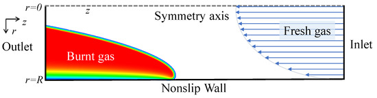
Figure 1.
Sketch of the numerical setup.
The initial internal structure of the flame is imitated using the analytical solution similar to that of Zeldovich and Frank-Kamenetskii [25,52]; see Ref. [42] for the details of the initial solution setting.
In the present simulations, a variable-resolution mesh is employed [24,42,50], which provides significant computational resource savings. This mesh consists of a subdomain with a higher resolution, specifically dedicated to capturing the flame front, while the remaining parts of the calculation domain employ a lower resolution, see, for example, Ref. [42]. To ensure an appropriate resolution of the reaction zone and achieve isotropic flame propagation properties, square cells with a size ranging from – are employed within the subdomain that contains the flame. The grid resolution varies gradually from one subdomain to another along the tube. The total length of the tube L is typically 100 times that of radius (), to eliminate the influence of the inlet boundary condition on the flame dynamics and to ensure that the critical condition can be attained far enough from the inlet. The flame is ignited at the bottom left corner as a sector of burnt gas with radius for each case, similar to Refs. [24,49]. The critical condition, at which the flame becomes stagnant within the tube, is attained by gradually adjusting the total flow rate at the inlet.
Resolution tests were conducted in the flame subdomain for various cell sizes, ranging from to . In these tests, the flame propagation velocity is measured for a channel with a radius of , under the conditions of , . The results of the resolution tests, summarized in Table 2, demonstrate the convergence of . A constant refinement ratio of was applied. The observed order of the truncation rate decay [53,54], denoted as , was found to be for , and for . These values are in reasonable agreement with the overall order of approximation. Based on the results of the resolution tests, a cell size of is selected for the range of from 20 to 100. When dealing with smaller tube radii within the range of from 6 to 20, a minimum cell size of is used in the subdomain containing the flame. Furthermore, for tube radii falling within the range of from 4 to 7, a minimum cell size of is employed in the subdomain containing the flame.
Table 2.
Resolution tests for the flame flashback speed (, , , ).
3. Results and Discussion
In this section, we explore the influence of the Lewis number () on flame shapes and radial consumption speed profiles under critical conditions. Specifically, we analyze the impact of different thermal expansion coefficients () and tube radii ranging from smaller sizes (), close to a quenching radius, to medium radii (). It is observed that, as the tube radius is increased, the flame shape transitions from mushroom-shaped to tulip-shaped.
It has been shown previously [24,30,33,34,35,38] that two different types of flame shapes can manifest themselves in small-scale channels under different conditions, one being a concave tulip-shaped flame, the other being a convex mushroom-shaped flame front. In the range of , denoted as “small” radii in the present study, the lower limit of R is close to the quenching limit. This is the range of R where a transition from a convex to a tulip-like shape of a flame is observed and studied in detail. In larger tubes with radii ranging from , the flame tip is generally located closer to the wall, where the flow velocity is lower compared to the tube axis region. Consequently, the flame maintains a shape qualitatively similar to a tulip shape in this range of R.
3.1. Tubes of Small Radius
When the tube diameters approach the quenching diameter, flame responses can become rather complex [55]. In the present subsection, the influence of the Lewis number on flame flashback in small tubes () is investigated, assuming all other parameters except for and R to be the same. Figure 2 illustrates the flame shapes under critical conditions for various tube radii R and Lewis numbers . It is observed from Figure 2 that, for a given Lewis number, the flame shape transitions from a mushroom shape to a tulip shape as the tube radius increases. Additionally, for a fixed radius, particularly for the cases with , it is seen that, as the Lewis number decreases, the flame tip moves closer to the wall, where the incoming flow velocity is lower, thus enhancing the flame flashback propensity, see the discussion below. For the cases with , characterized by a relatively higher thermal diffusivity, the flame is less likely to become concave at the centerline. As it will be shown next, it is also more prone to blowout as compared to cases with smaller Lewis numbers. In narrow tubes with radii not much larger than a quenching distance, the flame is stabilized via a global interaction with the oncoming flow. Therefore, in this subsection, we focus on the quantification of the maximum axial velocity at the critical condition, rather than a critical gradient. This approach is similar to that in Ref. [35].
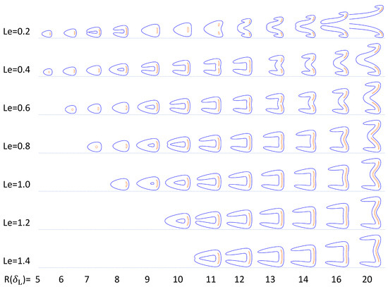
Figure 2.
Isolines of the normalized reaction rate at the critical condition for , , , shown by blue and orange lines, representing and , respectively. For each snapshot, the reaction rate is normalized with a respective maximum value.
Figure 3 shows the dependence of the critical velocity on the tube radius R for different . Similar to previous studies [24,34,35], for a certain , the dependence of the critical on R is non-monotonic. Like in Refs. [24,34,35], a slight decrease in the critical velocity occurs during the shift from a mushroom- to a tulip-shaped flame, as the radius increases. For example, for , a decrease in the critical velocity with the radius R can be observed in the range , see Figure 3, followed by an increase in with R. Thus, the critical condition for flashback is strongly impacted by the flame shape transition. It is seen from Figure 2 that, when the Lewis number , the minimum tube radius, at which the critical condition can be attained without quenching, decreases with . When is greater than one, the dependence of the critical velocity on R becomes weaker with ; still, a transition in the flame shape from a mushroom-shaped flame to a tulip-shaped flame is observed.
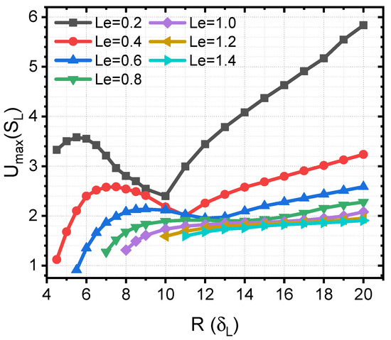
Figure 3.
Critical velocity at tube axis versus radius R at the critical condition for different .
Figure 4 illustrates the impact of thermal expansion on the critical for the flame flashback for . It is noted that attaining a critical state for the small radii, , can be challenging, as the flame tends to extinguish upon reaching the critical state for R in the vicinity of the quenching distance. A comparison of the critical as a function of R for and a fixed , shown in Figure 4, reveals that the value of R, at which there is a local minimum of the critical , associated with the flame shape transition, decreases with .
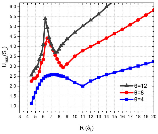
Figure 4.
Critical velocity at the tube axis versus radius R for different thermal expansion coefficients ().
Figure 5 illustrates the flame shapes for different values of and two different radii, highlighting the influence of the Lewis number on the flame shape under the critical condition. When the Lewis number is less than unity (e.g., the top row, ), an increase in the expansion coefficient results in a more concave flame shape at the tube axis, and the tip location moves closer to the wall. In contrast, when the Lewis number is greater than unity (see, e.g., the bottom row, ), the flame shapes are less likely to be concave at the tube axis, especially for the higher values of (see, e.g., the column for ).
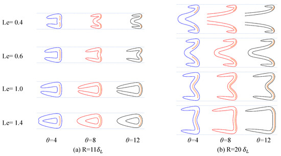
Figure 5.
Flame shape at different radii, (a) , (b) , , and at the critical condition. Blue, red, and black lines represent for , respectively. Orange lines indicate for all cases. For each snapshot, the reaction rate is normalized via a respective maximum value.
3.2. Tubes of Medium Radius
In this subsection, the radius of the tube is taken in the range . As the tube radius increases, the flame at the critical condition tends to acquire a tulip shape. This shift in the flame shape is accompanied by a transition in the flame dynamics at a subcritical velocity gradient, namely, a shift from a flashback happening against a core flow to a localized flashback happening closer to the wall is observed. We will focus our discussion on the critical conditions, at which flames can be stabilized at the wall, and refrain from discussing unsteady flames, which may develop in situations with very low [30].
An illustration of the field of reaction rate , quenching distance , penetration distance , and the profiles of the flow velocity and the consumption speed is presented in Figure 6. Utilizing a diagram of that kind, the consumption speed and flow velocity profiles can be directly compared using their graphical representations.
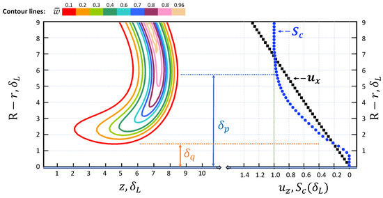
Figure 6.
An integrated illustration of the reaction rate field, quenching distance , penetration distance , and the profiles of the flow velocity and consumption speed . The position of the flame has been adjusted in the z direction for illustrative purposes. , .
Figure 7 illustrates the dependence of the critical velocity gradient g on tube radius R, for various and . The critical velocity gradient is calculated using the formula [24]. It is seen that for larger , the critical velocity gradient g tends to converge to a constant value for large radii, similar to the results of Ref. [24]. However, no convergence of g with R is observed for low in the range of R employed. It is apparent that g tends to increase with , in agreement with previous studies [30]. At very low and large R, as the flame reaches a close proximity of the critical state, the is elevated to very large values, leading to low instability and the emergence of small perturbations at the flame tail. This instability makes it challenging to sustain the critical state, increasing the likelihood of flame blowout.
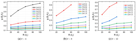
Figure 7.
Critical velocity gradient g as a function of R for various and . Subfigures (a–c) represent , respectively.
In Figure 8, a comparison of the radial profiles of the oncoming flow velocity and the flame consumption speed is presented. The algorithm for calculating the consumption speed profile is the same as in Refs. [24,49]. From Figure 8, it is evident that, in the vicinity of the wall, the consumption speed is significantly higher for cases with as compared to the cases with a Lewis number equal to unity or larger. Notably, the peak value of is observed around , close to the location of the flame tip. An increase in the burning rate at a flame tip for is a well-known phenomenon [25,43]; however, it may not always be readily observed in flashback scenarios due to wall heat losses [30]. As the Lewis number decreases, the peak value of increases. For example, for , the penetration distance (defined at the radial distance from the wall, at which the maximum of is attained) is approximately . However, for , the penetration distance decreases to around . As the penetration distance decreases with , the flashback tends to happen closer to the wall, naturally leading to a larger critical gradient. In cases with higher , such as , the peak values of are smaller than those of , suggesting that flame flashback is further inhibited as compared to .
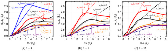
Figure 8.
Influence of Lewis number on the consumption speed and flow velocity near the wall for different . .
In Figure 9, for a critical condition, notable variations in the consumption speed profile () with thermal expansion coefficient are demonstrated for (see Figure 9a,b). These differences are particularly significant in cases with .
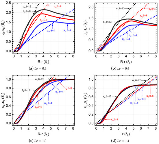
Figure 9.
Influence of thermal expansion on the flame consumption speed and flow velocity under critical condition for various . , .
It is seen that in cases with , only a minimal difference is observed in the profiles of the consumption speed () for different . The effect of the tube radius R on the consumption speed and flow velocity in the near-wall region is illustrated in Figure 10 for two values of Lewis numbers, both for . Consistent with Figure 7, the influence of the radius R on the profiles is non-negligible for flames in the range of R considered, and it is more noticeable for the lower value of .
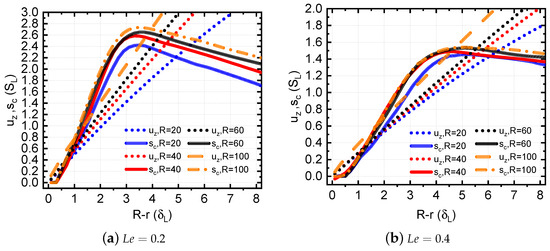
Figure 10.
Effect of tube radius R on consumption speed and flow velocity close to the wall for different Lewis numbers . , .
Figure 11 shows the flame shape under critical condition, represented by the isolines of the reaction rate, for different . For each snapshot, the reaction rate levels are normalized via the maximum reaction rate of the case. With the increase in Lewis number, the flame tip is shifted away from the wall, and the tip shape is modified in agreement with Figure 5. This explains why the increase in decreases the flashback tendency: as the flame tip is positioned further away from the wall, it faces a stronger flow. This finding is consistent with the results of Ref. [30].
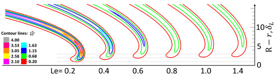
Figure 11.
Illustration of the flame shapes near the wall, based on the levels of the reaction rate field, for various at the critical condition. Non-dimensional reaction rate is scaled by the maximum reaction rate in the case. , .
In Figure 12, flame shapes based on the isolines of the normalized reaction rate are presented for different thermal expansion coefficients . It is evident that, for a critical condition, an increase in thermal expansion coefficient results in a displacement of the reaction rate isolines towards the wall. A significant shift is observed for the isoline : as the value of increases from 4 to 12, the distance between the isoline and the wall decreases by about a third. This leads to the flame tip facing a smaller flow velocity at higher . Thus, an increase in should result in increases in the flashback tendency, corroborating the results of Figure 4.
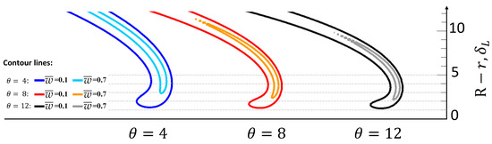
Figure 12.
Illustration of the flame shapes for various , based on the isolines of the normalized reaction rate at the critical condition for and at .
4. Summary
In this study, we focus on the effects of the Lewis number () on the configuration and responses of flames in tubes under the critical condition for flashback. Our investigation encompassed an examination of the influence of the thermal expansion coefficient () and the radius of tube R, which spanned from small ∼20 close to the flame quenching threshold to moderate ∼100. The main findings of this study are as follows:
- In tubes with smaller radii R, an increase in R prompts a transformation of the flame shape from a mushroom to a tulip configuration. For a given radius, flames at critical condition exhibit a tendency to approach the tube walls as the Lewis number decreases. In contrast, flames with a higher Lewis number, indicative of the increased relative role of thermal diffusivity, tend to be less concave at the tube axis.
- In tubes of moderate radii, the flame at the critical condition progressively shifts towards the wall with an increase in tube radius, adopting a tulip-like shape. For larger , this is accompanied by a saturation of the critical velocity gradient with the tube radius. The radial consumption speed profiles demonstrate noticeable local maxima when the Lewis number is below unity, and both the consumption speed and the flow velocity near the wall are influenced by the changes in both the Lewis number and the thermal expansion coefficient. A higher is correlated with a suppression of flame flashback occurrences.
Overall, the present findings highlight the complex interaction between the effects of Lewis number, thermal expansion, and tube radius in determining the flame shapes under critical conditions. These insights contribute to a better understanding of laminar flame flashback and, potentially, flame dynamics in different scenarios. Future research is needed to better understand the complex mechanisms at play for extremely small .
Author Contributions
Methodology, K.H., D.M.V. and L.B.; software, K.H. and D.M.V.; validation, K.H.; resources, D.M.V.; writing—original draft preparation, K.H.; writing—review and editing, D.M.V., L.B. and W.H.; investigation, K.H.; visualization, K.H.; supervision, D.M.V.; funding acquisition, D.M.V. and W.H. All authors have read and agreed to the published version of the manuscript.
Funding
This research was funded by the National Natural Science Foundation of China (NSFC) grant numbers 52176118 and 51750110503 and by the State Key Laboratory of Explosion Science and Technology (Beijing Institute of Technology) through open project no. KFJJ21–10M. W.H. is supported by the Shaanxi Institute of Applied Physical Chemistry grant number 6142602210408. Computations and data handling were enabled by resources provided by the Swedish National Infrastructure for Computing (SNIC) at High Performance Computing Center North (HPC2N), partially funded by the Swedish Research Council through Grant Agreement No. 2018-05973. The APC was funded by MDPI.
Institutional Review Board Statement
Not applicable.
Data Availability Statement
The data presented in this study are available on request from the corresponding author. The data are not publicly available due to large disk usage.
Acknowledgments
The authors are grateful to Chengxi Miao for useful discussions.
Conflicts of Interest
The authors declare no conflicts of interest. The funders had no role in the design of the study; in the collection, analyses, or interpretation of data; in the writing of the manuscript; or in the decision to publish the results.
Abbreviations and Nomenclature
| BLF | boundary layer flashback |
| CGM | critical gradient model |
| sound speed, m/s | |
| heat capacity at constant pressure, | |
| heat capacity at constant volume, | |
| activation energy, J/mol | |
| g | velocity gradient, |
| l | cell size, scaled by |
| Lewis number | |
| flame propagation Mach number | |
| P | pressure, Pa |
| order of truncation error decay | |
| Prandtl number | |
| energy diffusion vector | |
| Q | energy release from the reaction |
| R | tube radius, scaled by |
| universal gas constant, | |
| Schmidt number | |
| consumption speed, scaled by | |
| unstretched laminar burning velocity, m/s | |
| t | time, , scaled by |
| T | temperature, K |
| velocity, scaled by | |
| w | reaction rate, |
| z | axial coordinate, scaled by |
| r | radial coordinate, scaled by |
| Y | mass fraction of fuel |
| Zeldovich number | |
| Kronecker delta | |
| laminar flame thickness, m | |
| quenching distance, scaled by | |
| penetration distance, scaled by | |
| total energy per unit volume | |
| Arrhenius number | |
| stress tensor | |
| adiabatic index | |
| gas expansion ratio | |
| dynamic viscosity, | |
| density, | |
| factor of time dimension in the Arrhenius law, s | |
| Subscripts | |
| 0 | initial value |
| b | burnt gas |
| c | consumption |
| maximum (centerline) | |
| flame tip | |
| L | laminar unstretched flame |
| Other designations | |
| scaled value | |
| normalized value | |
References
- Kalantari, A.; McDonell, V. Boundary layer flashback of non-swirling premixed flames: Mechanisms, fundamental research, and recent advances. Prog. Energy Combust. Sci. 2017, 61, 249–292. [Google Scholar] [CrossRef]
- Gruber, A.; Chen, J.H.; Valiev, D.; Law, C.K. Direct numerical simulation of premixed flame boundary layer flashback in turbulent channel flow. J. Fluid Mech. 2012, 709, 516–542. [Google Scholar] [CrossRef]
- Zhang, W.; Li, Y. Progress in Mechanisms and Numerical Simulation of Flame Flashback for Gas Turbine. J. Combust. Sci. Technol. 2016, 22, 385–401. [Google Scholar]
- Jiang, X.; Tang, Y.; Liu, Z.; Raman, V. Computational Modeling of Boundary Layer Flashback in a Swirling Stratified Flame Using a LES-Based Non-Adiabatic Tabulated Chemistry Approach. Entropy 2021, 23, 567. [Google Scholar] [CrossRef] [PubMed]
- Vigueras-Zuniga, M.O.; Tejeda-del Cueto, M.E.; Vasquez-Santacruz, J.A.; Herrera-May, A.L.; Valera-Medina, A. Numerical Predictions of a Swirl Combustor Using Complex Chemistry Fueled with Ammonia/Hydrogen Blends. Energies 2020, 13, 288. [Google Scholar] [CrossRef]
- Benim, A.; Syed, K. Flashback Mechanisms in Lean Premixed Gas Turbine Combustion; Elsevier Science: Amsterdam, The Netherlands, 2014. [Google Scholar]
- de Vries, H.; Mokhov, A.V.; Levinsky, H.B. The impact of natural gas/hydrogen mixtures on the performance of end-use equipment: Interchangeability analysis for domestic appliances. Appl. Energy 2017, 208, 1007–1019. [Google Scholar] [CrossRef]
- Fursenko, R.; Sereshchenko, E.; Uriupin, G.; Odintsov, E.; Tezuka, T.; Minaev, S.; Maruta, K. Experimental and numerical study of premixed flame penetration and propagation in multichannel system. Combust. Sci. Technol. 2018, 190, 1023–1040. [Google Scholar] [CrossRef]
- Goldmann, A.; Dinkelacker, F. Experimental investigation and modeling of boundary layer flashback for non-swirling premixed hydrogen/ammonia/air flames. Combust. Flame 2021, 226, 362–379. [Google Scholar] [CrossRef]
- Gruber, A.; Kerstein, A.R.; Valiev, D.; Law, C.K.; Kolla, H.; Chen, J.H. Modeling of mean flame shape during premixed flame flashback in turbulent boundary layers. Proc. Combust. Inst. 2015, 35, 1485–1492. [Google Scholar] [CrossRef]
- Gruber, A.; Richardson, E.S.; Aditya, K.; Chen, J.H. Direct numerical simulations of premixed and stratified flame propagation in turbulent channel flow. Phys. Rev. Fluids 2018, 3, 110507. [Google Scholar] [CrossRef]
- Zhu, Z.; Wang, H.; Chen, G.; Luo, K.; Fan, J. Interactions of turbulence and flame during turbulent boundary layer premixed flame flashback under isothermal and adiabatic wall conditions using direct numerical simulation. Phys. Fluids 2023, 35, 125106. [Google Scholar] [CrossRef]
- Endres, A.; Sattelmayer, T. Large Eddy simulation of confined turbulent boundary layer flashback of premixed hydrogen-air flames. Int. J. Heat Fluid Flow 2018, 72, 151–160. [Google Scholar] [CrossRef]
- Endres, A.; Sattelmayer, T. Numerical Investigation of Pressure Influence on the Confined Turbulent Boundary Layer Flashback Process. Fluids 2019, 4, 146. [Google Scholar] [CrossRef]
- Endres, A.Ö. Numerical Modelling of Boundary Layer Flashback in Premixed Hydrogen-Air Combustion Systems. Ph.D. Thesis, Technische Universität München, München, Germany, 2020. [Google Scholar]
- Xia, H.; Han, W.; Wei, X.; Zhang, M.; Wang, J.; Huang, Z.; Hasse, C. Numerical investigation of boundary layer flashback of CH4/H2/air swirl flames under different thermal boundary conditions in a bluff-body swirl burner. Proc. Combust. Inst. 2023, 39, 4541–4551. [Google Scholar] [CrossRef]
- Vance, F.H.; De Goey, L.; van Oijen, J.A. Development of a flashback correlation for burner-stabilized hydrogen-air premixed flames. Combust. Flame 2022, 243, 112045. [Google Scholar] [CrossRef]
- Kıymaz, T.B.; Böncü, E.; Güleryüz, D.; Karaca, M.; Yılmaz, B.; Allouis, C.; Gökalp, İ. Numerical investigations on flashback dynamics of premixed methane-hydrogen-air laminar flames. Int. J. Hydrogen Energy 2022, 47, 25022–25033. [Google Scholar] [CrossRef]
- Fruzza, F.; Lamioni, R.; Tognotti, L.; Galletti, C. Flashback of H2-enriched premixed flames in perforated burners: Numerical prediction of critical velocity. Int. J. Hydrogen Energy 2023, 48, 31790–31801. [Google Scholar] [CrossRef]
- Fruzza, F.; Lamioni, R.; Mariotti, A.; Salvetti, M.V.; Galletti, C. Flashback propensity due to hydrogen blending in natural gas: Sensitivity to operating and geometrical parameters. Fuel 2024, 362, 130838. [Google Scholar] [CrossRef]
- Leask, S.; McDonell, V.; Samuelsen, G.S. Neural Network Prediction of Boundary Layer Flashback. J. Eng. Gas Turbines Power 2021, 143, 054501. [Google Scholar] [CrossRef]
- Lewis, B.; von Elbe, G. Stability and structure of burner flames. J. Chem. Phys. 1943, 11, 75–97. [Google Scholar] [CrossRef]
- Von Elbe, G.; Mentser, M. Further studies of the structure and stability of burner flames. J. Chem. Phys. 1945, 13, 89–100. [Google Scholar] [CrossRef]
- Huang, K.; Valiev, D.M.; Zhong, H.; Han, W. Numerical Study of the Influence of the Thermal Gas Expansion on the Boundary Layer Flame Flashback in Channels with Different Wall Thermal Conditions. Energies 2023, 16, 1844. [Google Scholar] [CrossRef]
- Law, C.K. Combustion Physics; Cambridge University Press: Cambridge, UK, 2006. [Google Scholar]
- Ronney, P.D. Near-limit flame structures at low Lewis number. Combust. Flame 1990, 82, 1–14. [Google Scholar] [CrossRef]
- Lewis, B.; Von Elbe, G. Combustion, Flames and Explosions of Gases; Elsevier: Amsterdam, The Netherlands, 1987. [Google Scholar]
- Alliche, M.; Haldenwang, P.; Chikh, S. Extinction conditions of a premixed flame in a channel. Combust. Flame 2010, 157, 1060–1070. [Google Scholar] [CrossRef]
- Kurdyumov, V.; Fernández, E.; Linan, A. Flame flashback and propagation of premixed flames near a wall. Proc. Combust. Inst. 2000, 28, 1883–1889. [Google Scholar] [CrossRef]
- Kurdyumov, V.N.; Fernandez-Tarrazo, E. Lewis number effect on the propagation of premixed laminar flames in narrow open ducts. Combust. Flame 2002, 128, 382–394. [Google Scholar] [CrossRef]
- Kurdyumov, V.; Fernández-Tarrazo, E.; Truffaut, J.M.; Quinard, J.; Wangher, A.; Searby, G. Experimental and numerical study of premixed flame flashback. Proc. Combust. Inst. 2007, 31, 1275–1282. [Google Scholar] [CrossRef]
- Feng, R.; Gruber, A.; Chen, J.H.; Valiev, D.M. Influence of gas expansion on the propagation of a premixed flame in a spatially periodic shear flow. Combust. Flame 2021, 227, 421–427. [Google Scholar] [CrossRef]
- Wohl, K.; Kapp, N.M.; Gazley, C. The stability of open flames. Symp. Combust. Flame Explos. Phenom. 1948, 3, 3–21. [Google Scholar] [CrossRef]
- Hackert, C.L.; Ellzey, J.L.; Ezekoye, O.A. Effects of thermal boundary conditions on flame shape and quenching in ducts. Combust. Flame 1998, 112, 73–84. [Google Scholar] [CrossRef]
- Tsai, C.H. The Asymmetric Behavior of Steady Laminar Flame Propagation in Ducts. Combust. Sci. Technol. 2008, 180, 533–545. [Google Scholar] [CrossRef]
- Ju, Y.; Xu, B.O. Effects of channel width and Lewis number on the multiple flame regimes and propagation limits in mesoscale. Combust. Sci. Technol. 2006, 178, 1723–1753. [Google Scholar] [CrossRef]
- Chakraborty, S.; Mukhopadhyay, A.; Sen, S. Interaction of Lewis number and heat loss effects for a laminar premixed flame propagating in a channel. Int. J. Therm. Sci. 2008, 47, 84–92. [Google Scholar] [CrossRef]
- Bioche, K.; Vervisch, L.; Ribert, G. Premixed flame-wall interaction in a narrow channel: Impact of wall thermal conductivity and heat losses. J. Fluid Mech. 2018, 856, 5–35. [Google Scholar] [CrossRef]
- Eriksson, L.E. A Third Order Accurate Upwind-Biased Finite-Volume Scheme for Unsteady Compressible Viscous Flow; Volvo Aero Corporation: Trollhättan, Sweden, 1993. [Google Scholar]
- Eriksson, L.E. Flow solution on a dual-block grid around an airplane. Comput. Methods Appl. Mech. Eng. 1987, 64, 79–93. [Google Scholar] [CrossRef]
- Demirgok, B.; Ugarte, O.; Valiev, D.; Akkerman, V. Effect of thermal expansion on flame propagation in channels with nonslip walls. Proc. Combust. Inst. 2015, 35, 929–936. [Google Scholar] [CrossRef]
- Valiev, D.; Bychkov, V.; Akkerman, V.; Eriksson, L.E.; Law, C.K. Quasi-steady stages in the process of premixed flame acceleration in narrow channels. Phys. Fluids 2013, 25, 096101. [Google Scholar] [CrossRef]
- Alkhabbaz, M.; Abidakun, O.; Valiev, D.; Akkerman, V. Impact of the Lewis number on finger flame acceleration at the early stage of burning in channels and tubes. Phys. Fluids 2019, 31, 083606. [Google Scholar] [CrossRef]
- Akkerman, V.; Valiev, D. Moderation of flame acceleration in obstructed cylindrical pipes due to gas compression. Phys. Fluids 2018, 30, 106101. [Google Scholar] [CrossRef]
- Wu, M.H.; Wang, C.Y. Reaction propagation modes in millimeter-scale tubes for ethylene/oxygen mixtures. Proc. Combust. Inst. 2011, 33, 2287–2293. [Google Scholar] [CrossRef]
- Poinsot, T.; Veynante, D. Theoretical and Numerical Combustion; RT Edwards, Inc.: Dallas, TX, USA, 2005. [Google Scholar]
- Adebiyi, A.; Abidakun, O.; Akkerman, V. Acceleration of Premixed Flames in Obstructed Pipes with Both Extremes Open. Energies 2020, 13, 4094. [Google Scholar] [CrossRef]
- Attili, A.; Lamioni, R.; Berger, L.; Kleinheinz, K.; Lapenna, P.E.; Pitsch, H.; Creta, F. The effect of pressure on the hydrodynamic stability limit of premixed flames. Proc. Combust. Inst. 2021, 38, 1973–1981. [Google Scholar] [CrossRef]
- Ding, S.; Huang, K.; Han, Y.; Valiev, D. Numerical study of the influence of wall roughness on laminar boundary layer flashback. Phys. Rev. Fluids 2021, 6, 023201. [Google Scholar] [CrossRef]
- Feng, R.; Valiev, D. Influence of gas expansion on the velocity and stability limits of stationary curved flames in channels. Combust. Sci. Technol. 2022. [Google Scholar] [CrossRef]
- Schlichting, H.; Gersten, K. Boundary-Layer Theory, 9th ed.; Springer: Berlin/Heidelberg, Germany, 2016. [Google Scholar]
- Zeldovich, I.B.; Barenblatt, G.I.; Librovich, V.B.; Makhviladze, G.M. Mathematical Theory of Combustion and Explosions; Consultants Bureau: New York, NY, USA, 1985. [Google Scholar]
- Versteeg, H.K.; Malalasekera, W. An Introduction to Computational Fluid Dynamics: The Finite Volume Method; Pearson Education: London, UK, 2007. [Google Scholar]
- Abidakun, O.; Adebiyi, A.; Valiev, D.; Akkerman, V. Nonequidiffusive premixed-flame propagation in obstructed channels with open, nonreflecting ends. Phys. Rev. E 2022, 105, 015104. [Google Scholar] [CrossRef]
- Wan, J.; Fan, A. Recent progress in flame stabilization technologies for combustion-based micro energy and power systems. Fuel 2021, 286, 119391. [Google Scholar] [CrossRef]
Disclaimer/Publisher’s Note: The statements, opinions and data contained in all publications are solely those of the individual author(s) and contributor(s) and not of MDPI and/or the editor(s). MDPI and/or the editor(s) disclaim responsibility for any injury to people or property resulting from any ideas, methods, instructions or products referred to in the content. |
© 2024 by the authors. Licensee MDPI, Basel, Switzerland. This article is an open access article distributed under the terms and conditions of the Creative Commons Attribution (CC BY) license (https://creativecommons.org/licenses/by/4.0/).