Abstract
In motorsports, the correct design of every device that constitutes a vehicle is a significant task for engineers because the car’s efficiency on the track depends on making it competitive. However, the physical integrity of the pilot is also at stake, since a bad vehicle design can cause serious mishaps. To achieve the correct development of a front wing for a single-seater vehicle, it is necessary to adequately simulate the forces that are generated on a car to evaluate its performance, which depends on the aerodynamic forces of the front wing that are present due to its geometry. This work provided a new design and evaluation through the numerical analysis of three new front wings for single-seater vehicles that comply with the regulations issued by the International Automobile Federation (FIA) for the 2022 season. Additionally, a 3D-printed front wing prototype was developed to be evaluated in an experimental study to corroborate the results obtained through computer simulations. A wind tunnel experiment test was performed to validate the numerically simulated data. Also, we developed a numerical simulation and characterization of three front wings already used in Formula One from a previous season (the end of the 2021 season). This work defined how these devices perform, and in the same way, it identified how their evolution over time has provided them with substantial benefits and greater efficiency. All the numerical simulations were carried out by applying the Finite Volume Method, allowing us to obtain the values of the aerodynamic forces that act on the front wing. Also, it was possible to establish a comparison between the three newly designed proposals from the most aerodynamic advantages to produce a prototype and perform an experimental test. The results of the experimental test showed similarity to those of the numerical analyses, making it clear that the methodology followed during the development of the work was correct. In addition, the mechanical designs carried out to develop the front wing can be considered ideal, because the results showed that the front wing could be competitive, and applying it caused a downforce to be favored that prevented the car from being thrown off the track. Additionally, the results indicate this is an effective proposal for use in a single-seater vehicle and that the design methodology delivers optimal results.
1. Introduction
Formula One is the most relevant motorsport category worldwide, making this competition the hardest testing ground to develop and evaluate new technologies. The aerodynamics knowledge applied to automobile design (and their parts) makes it possible to provide new features which allow them to reach high speeds and perform better than conventional vehicles. Participating teams use different car devices to take advantage of aerodynamics to achieve ideal performance. Among these devices are ailerons, of which, the car’s front wing is one of the most important. Initially, ailerons were developed as a control component attached to aircraft wings [1]. The first competition car that used an aileron device was produced by Michael May, who presented a Porsche Spyder with a spoiler attached to the top of the body in 1956. Unfortunately, it was never able to compete [2]. In Formula One, the application of spoilers came from Colin Chapman’s design of the Lotus 49B in 1967. This car had a front spoiler consisting of two fins with small endplates attached to the vehicle nose; despite its simplicity, this spoiler led to the use of aileron devices in the Formula One championship [3]. To understand the importance of the front wings in vehicle operation, it is necessary to understand aerodynamics theory, which is a branch of mechanics that studies the behavior of a body that interacts with moving air or that moves through fluid [4]. Due to the high speeds that Formula One vehicles reach, it is essential to achieve good performance by applying aerodynamics to streamline the car’s movement over the track. However, aerodynamics not only serves to increase the efficiency of the vehicle, but it is also necessary to make it safe to drive. Due to the speeds that single-seaters can reach, the probability of them detaching from the track and causing a serious mishap is high. Therefore, aerodynamics is equally essential when designing these cars [5]. For the Formula One 2022 season, the International Automobile Federation (FIA) proposed a new technical regulation involving a radical change in the aerodynamic design of vehicles [6]. This change created the need to redesign car bodies to adjust them to the new regulations. This work focused on the design of the most important aerodynamic part, a new front wing, which adapts to the regulations and complies with efficiency in its role, making the car competitive.
It is extremely important to design an aerodynamically efficient front wing since this device is expected to generate around 30% of the total downforce on a car, thus making it the most important device for the overall performance of the car [7,8]. The consequences of this device not performing correctly not only include poor performance during competitions, but the poor operation of the front wing during a race can also lead to serious accidents that, in the worst case, can lead to the loss of life.
Much of the technology present in commercially sold automobiles has used the Formula One championship as a testing ground due to the constant struggle of the teams to produce vehicles with higher performance; innovations such as the use of carbon fiber, rear-mounted engines, adaptable suspensions, and good aerodynamic efficiency are some of the advances that have been launched on Formula One tracks [9,10,11,12].
The development of this work began with computer simulations to characterize three front wings that were part of vehicles in Formula One seasons before the change in regulations from 2022; two of these front wings were parts of vehicles belonging to the McLaren and Williams teams, while the third was based on the front wing used by the Mercedes team in the 2021 season, achieving a very exact approximation to the real model. With this characterization, how these devices work was defined, as well as the characteristics that led to the development of a front wing with qualities that make it competitive without losing its operation, making it a safe and reliable device.
After the characterization of the background, the design of the new models proposed by the work team was carried out; three new front wings were presented that respond to the operating needs of these devices. In addition, these fully adapt to the new technical regulations. These new proposals were also submitted to computer simulations under critical operating conditions to analyze their aerodynamic and structural behavior to confirm that their performance is optimal according to the needs required by the vehicle on the track.
With the results of the aerodynamic forces acting on the wing, it was possible to select the best of the three models to later produce a scale prototype using 3D printing.
This prototype was subjected to experimental tests in a wind tunnel, obtaining data on the forces that act on the device; these data were compared with a new series of data obtained from computer simulations replicating the operating conditions to which the experimental tests were subjected to verify and validate the studies carried out using the software.
2. Theoretical Framework
Aerodynamics is defined as the study of mechanics involved in the behavior of bodies that interact with air in motion or move through the air [1,4].
In all the studies that are carried out to analyze the aerodynamic behavior of automobiles, it is simulated that the air circulates freely around the surface of the vehicle; considering this, it is necessary to understand the equation for the conservation of mass for moving flows:
Equation (1) is the differential form that presents the law of conservation of mass. The mass flux density is represented by the vector . The magnitude is equal to the fluid’s mass that passes in a unit of time through a unit area normal to the velocity vector . This equation is also commonly called the continuity equation [13].
In this article, the Reynolds-Averaged Navier–Stokes method (RANS) is used for the steady state of the simulation [14], in which the standard k-epsilon model is used as the basic turbulence model. The governing equations are shown below [15,16]:
Navier–Stokes equation:
where P is the pressure of fluids acting on tiny bodies, and are the velocity components, and is the density of fluid.
transport equation:
transport equation:
To define the terms that appeared in Equations (3) and (4), the following are given:
The constants are as follows: = 1.30, = 1.00, = 1.44, = 1.90, and = 0.09.
In the study of aerodynamic elements, there are dimensionless variables called aerodynamic coefficients which offer a description of the behavior of the element during its movement through the air. Three main coefficients are used depending on the parameter to be known, with these being CL (lift), CD (drag), and CY (yaw moment):
In these equations L represents the lift force, D is the drag force, and Y is the yaw moment force; all of these forces act directly on the element due to the pressures exerted by the airflow [17].
3. Background and Numerical Methodology
3.1. Front Wing Modeling for Background Profile
To set a precedent and learn about the aerodynamic behavior of the front wings in Formula One over the years, initially, in this work, we performed a characterization of three different models of front wings that have been part of single-seaters used in past seasons. To carry out this characterization, computer simulations were developed under identical conditions for the three front wings, using an airflow speed of 325 km/h, applying the Fluent tool from ANSYS® Workbench software [18]. The front wings subjected to simulation were those of the McLaren MP4/4, Williams FW31, and the front wing based on the Mercedes-AMG W12. With this characterization, it was possible to define the aerodynamic behavior of the front wings used in cars that competed in the Formula One championship in previous seasons to make a comparison between these models and the new models that comply with the 2022 regulations.
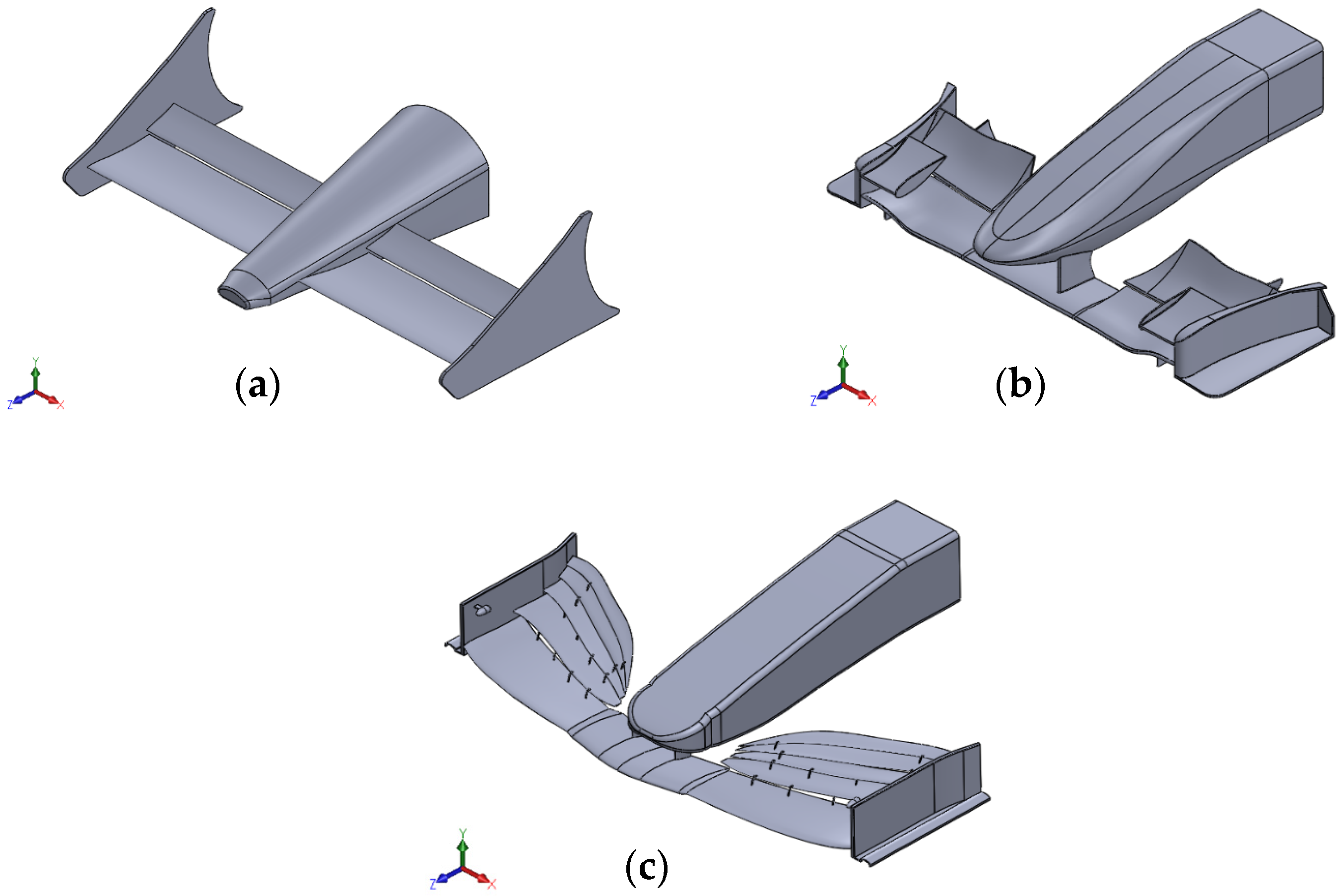
The first analysis was performed on the front wing of the MP4/4 (Figure 1a); the vehicle was designed by the McLaren team for the 1988 season and has been one of the vehicle legends in automotive design, since it has been one of the single-seaters that have won the most [19], with a record of 15 of 16 race wins during the season and winning the constructors’ and drivers’ championships; its top speed was 333 km/h [20]. As a second evaluation, the front wing of the FW31 (Figure 1b) was selected, which was also single-seater, which in this case was designed by the Williams team to compete in the 2009 season. This vehicle could exceed 330 km/h on straight lines, and despite it having a design with many aerodynamic features, it only managed to achieve seventh position in the Formula One constructors’ championship [21]. To complete the background profile, the front wing inspired by the W12 single-seater (Figure 1c), presented by the Mercedes-AMG team for the 2021 season, was chosen as the third option; this vehicle also showed efficiency and a great design, reaching speeds of over 330 km/h, and it won the constructors’ championship before the change in regulations [22].

Figure 1.
Front wings. (a) McLaren MP4/4; (b) Williams FW31; (c) Mercedes-AMG W12 (based).
3.2. Wind Tunnel Numerical Simulation
To conduct the simulation, the first step was to define a control volume with dimensions of 1.50 m width, 1 m height, and 4 m length; this volume worked by imitating a wind tunnel with a front airflow inlet and a zero-static pressure outlet to simulate the operation of the front wing outdoors.
The flow velocity was considered as a one-dimensional streamwise velocity, the magnitude of which had a maximum speed of 325 km/h, replicating the critical speed conditions for a Formula One car. The fluid conditions were defined to replicate the characteristics of the air at sea level according to the characteristics of an International Standard Atmosphere. Table 1 shows the characteristics of the fluid.

Table 1.
Fluid and flow properties.
With the tunnel and front wing model together, the discretization of the complete system could be carried out; since, in this process, it was only desired to know the behavior of the region through which the air flows around the front wing, the control volume was divided into smaller components to be using by the Finite Volume Method (Finite Element Method for fluid dynamics). For the analyses, fine discretization parameters and a semi-controlled method were used, as well as high-order elements [23].
The boundary conditions for this simulation, as well as for the rest of those presented in this work, were defined in the Fluent setup, for which a constant flow of air was used at a speed of 325 km/h normal to the boundary and a turbulence intensity of 5%. The static pressure at the exit of the tunnel was equal to zero (Figure 2). The left, right, and top walls had symmetry boundary conditions, while the ground wall that represented the asphalt on the track had a no-slip moving wall boundary condition. The front wing surface had a boundary condition of a no-slip stationary wall. To ensure the optimal convergence of the solution, the simulations were carried out with several iterations independent of the results for each case of analysis to obtain homogeneity in the values of the aerodynamic forces and the residuals [3].
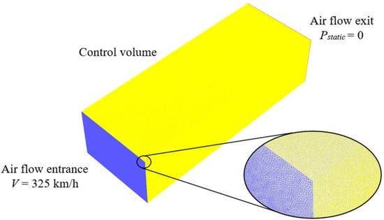
Figure 2.
Wind tunnel boundary conditions.
Aerodynamic analyses that were developed using the Fluent tool allowed for each case study to obtain a diverse series of graphic results where it highlighted the pressures on the surface of the wing, air pressures around the wing, and the air speeds that circulate the front wing.
4. Design of New Front Wings
4.1. Technical Regulations
Knowing the detailed operation and the necessary qualities to produce an aerodynamically efficient front wing thanks to the development of the background profile, the next step was to proceed to the design of three completely new proposals that complied to the new regulations. The Formula One technical regulations for the 2022 season specified the characteristics that a front wing must comply with to be used in competition; Table 2 specifies the articles, as well as the annexes that concern the design of the front wing [6].
Table 2.
Technical regulations of Formula One in 2022 for the design of the front wing.
4.2. New Front Wings Modeling
To carry out the modeling of the proposals, the CAD SolidWorks® design software was used; within the regulations, the reference volumes are specified (Figure 3), which describe the maximum size that the front wings can reach to be considered legal and to be able to be used in competition.
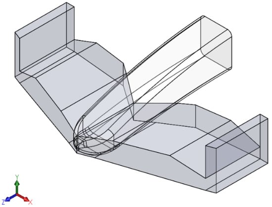
Figure 3.
Reference volumes for the front wing.
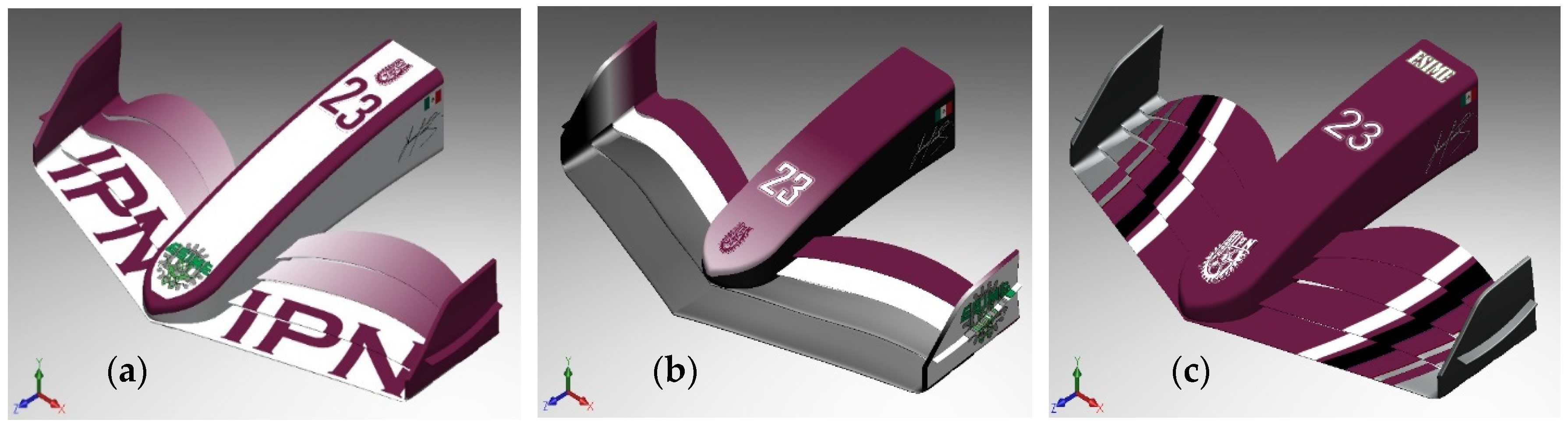
For the design of the proposals, a different aerodynamic profile was used for each of the new front wings. The proposals received a name to be able to identify them more easily; the names given were MICC-75, CLV-54, and JJRC-10 (Figure 4), and for their designs, the aerodynamic airfoils GOE-195, ISA-960, and S4320 were used, respectively [24].
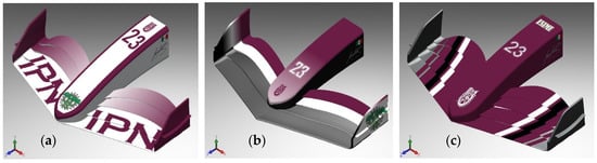
Figure 4.
(a) MICC-75; (b) CLV-54; (c) JJRC-10.
Due to the specifications of the new technical regulation, these devices have a characteristic silhouette in which a simple but aerodynamically efficient figure can be highlighted compared to the front wings before the change; eliminating the obligatory central section and the pylons that connected the nose of the car with the front wing [25] causes the flaps to be mounted directly on the nose, making the whole assembly more structurally stable. Another notable change to the 2022 silhouette is that the flaps and endplate come together more fluidly as one piece, resembling a bended winglet [26].
4.3. Numerical Analysis
In the same way, as with the front wings that were used to create the background profile, the three designed proposals were subjected to a numerical analysis in a wind tunnel using the Fluent tool under the same boundary conditions, where the velocity of the flow of air that circulated through the tunnel was 325 km/h, replicating the critical condition of the maximum speed reached in a straight line by the single-seater. For this second series of simulations, fine and semi-controlled discretization was used, as well as high-order elements (Figure 5) [23]. To perceive the effects caused by the boundary layer, a treatment was carried out on the mesh on the wall of the front wing; using inflation layers, it was possible to integrate further refinement to the model in the mesh around the wall. For the analyses carried out in this paper, a number of 25 elements around the wall and a growth rate of 1.1 were used. Using triangular elements, it was possible to keep the value of y+ between 40 and 100, as recommended for this variable [27].
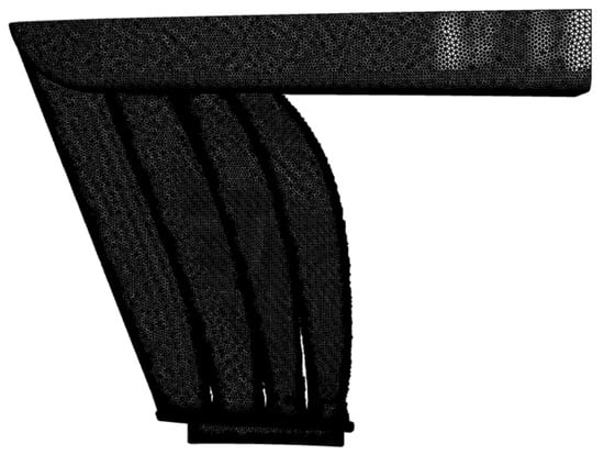
Figure 5.
Mesh of the MICC-75.
The results for the variables of pressure on the surface, the air pressure around the front wing, and the speeds of the air that circulates the front wing are shown below.
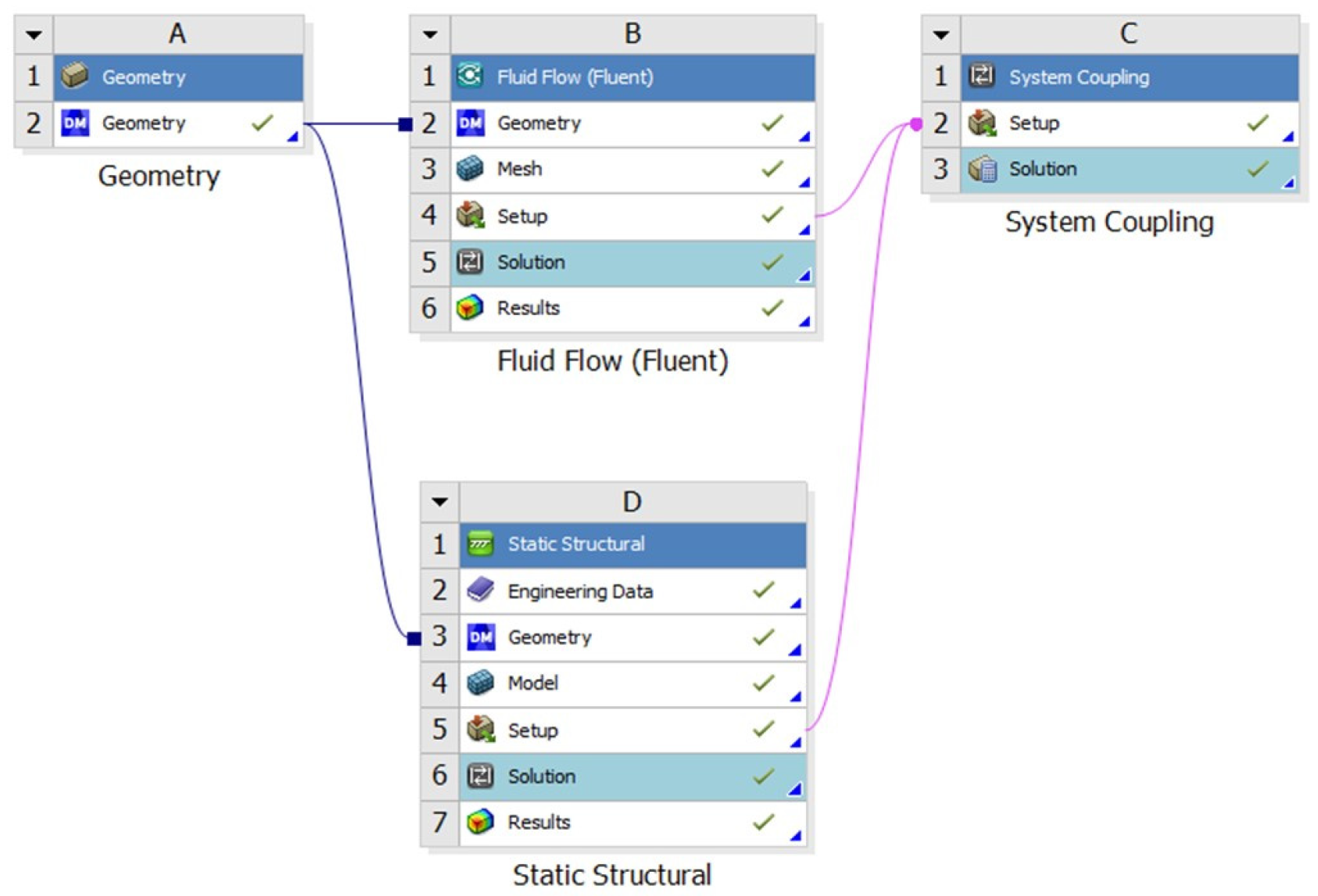
To complement the analysis of the designed front wings, a structural study was carried out to validate their structural integrity in critical conditions. To carry out this complementary analysis, the static structural tool was integrated into the ANSYS® Workbench software using the System Coupling tool (Figure 6). This complement allows the results of pressures exerted on the front wing to be transferred using the Fluent tool and exported as condition loads to be able to carry out a static study [28].

Figure 6.
System Coupling.
As with the aerodynamic analyses, it was necessary to carry out the discretization of the system, in this case, the front wing and its internal structure, for which a fine and semi-controlled mesh with high-order elements was used [23]. To perform this structural study, it was necessary to define the material for which the proposals were made. Within the FIA technical regulations for the Formula One championship, in article 15.3, the materials allowed for the construction of the single-seater are defined; in this study, Hexcel HM63 carbon fiber of 12,000 filaments was selected, and the physical properties of this material are specified in Table 3.
Table 3.
Hexcel HM63 properties.
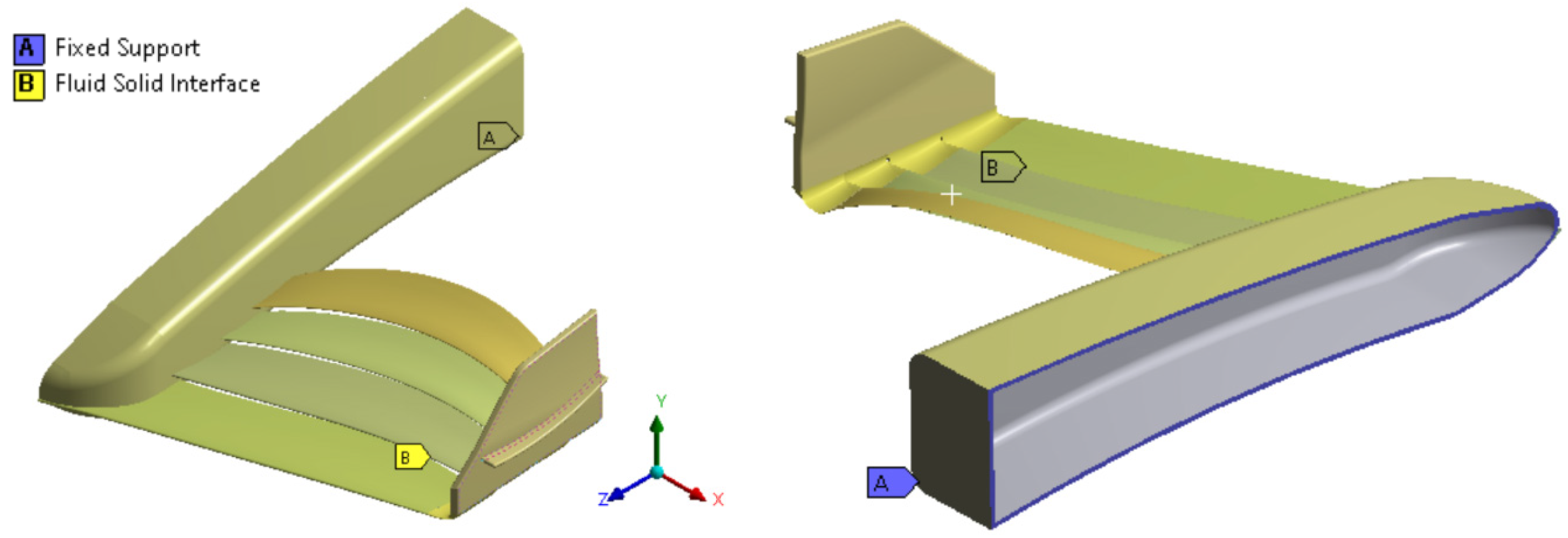
After selecting the material, it was vital to define the boundary conditions to carry out the study; for this, a fixed support was placed at the inner end of the nose of the front wing, simulating that it was attached to the rest of the car, and all the parts were defined, with their surfaces as the interaction zone between the fluid and the solid (Figure 7); these same boundary conditions were applied to the three proposals designed.

Figure 7.
Boundary conditions for the static structural study.
5. Results for Aerodynamic Background Profile
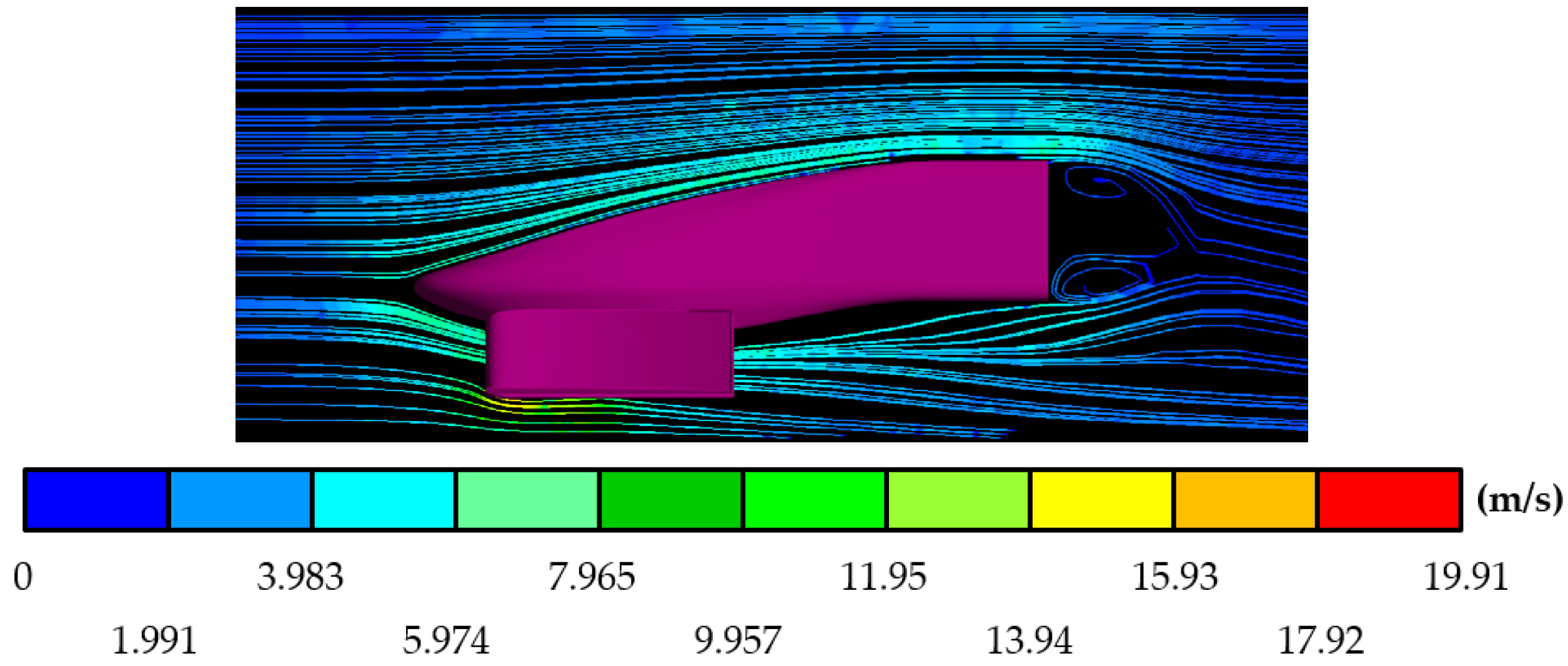
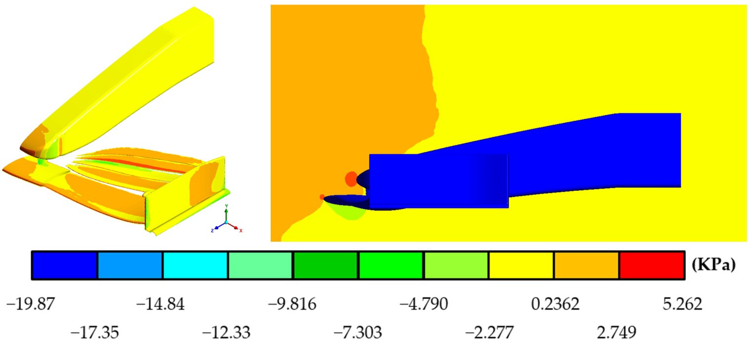
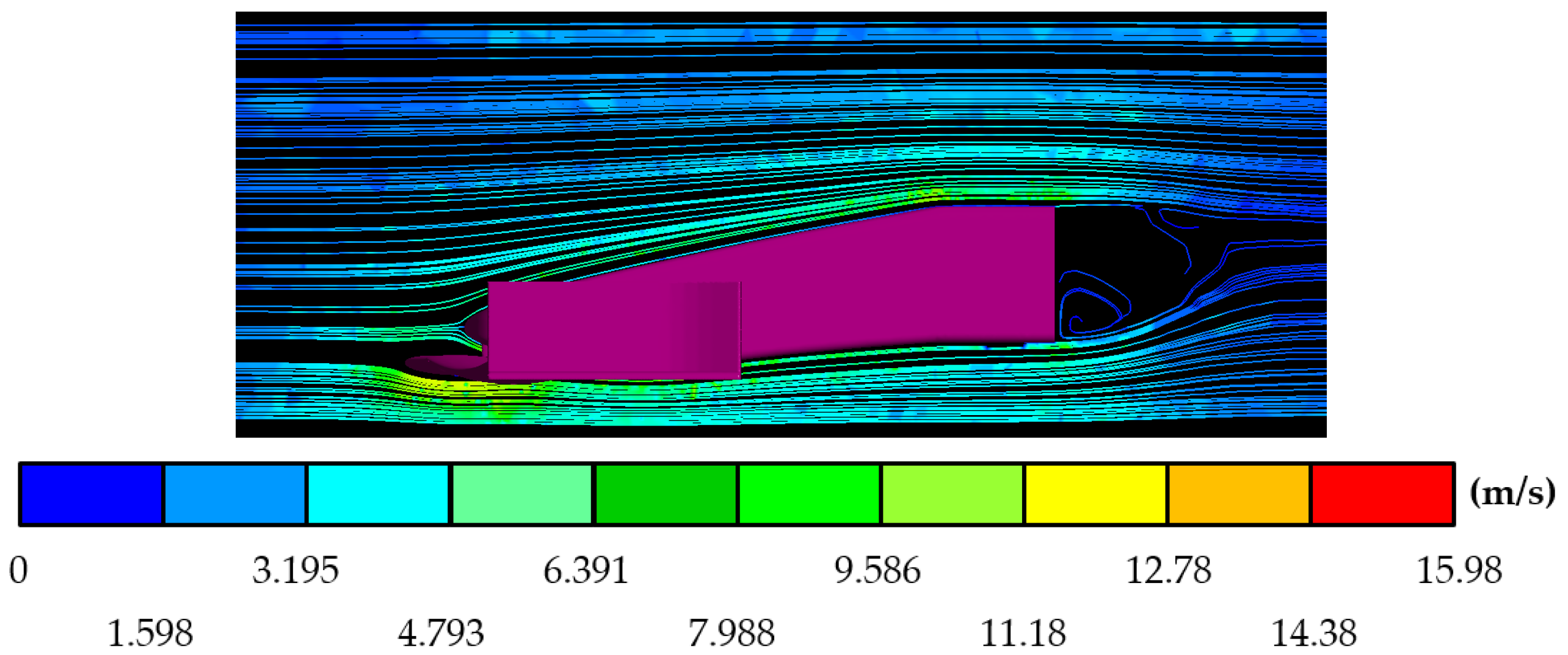
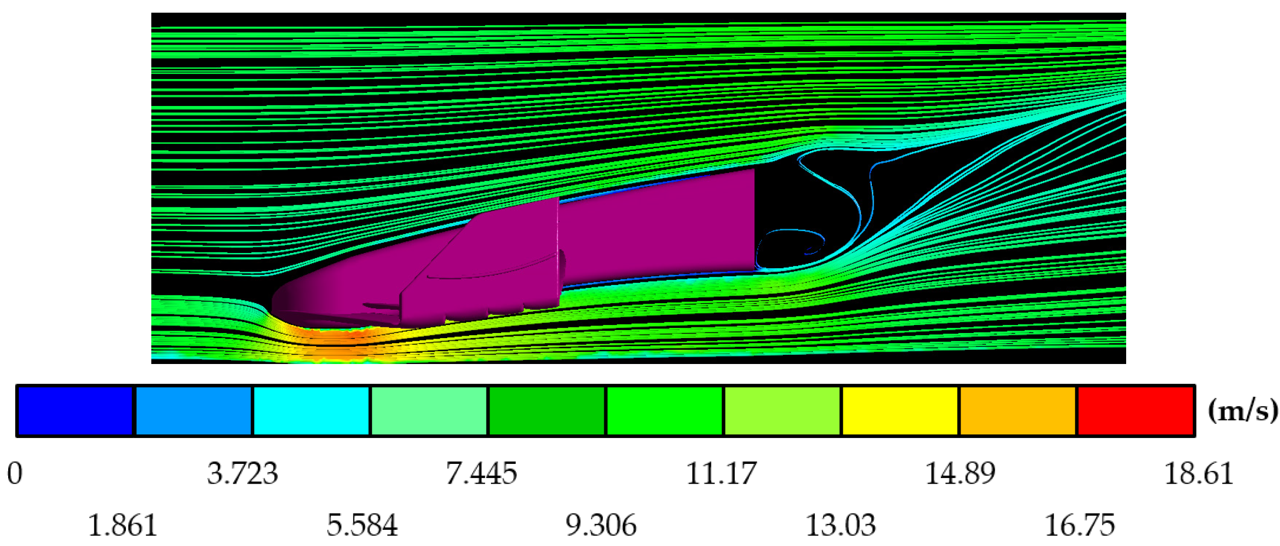
The graphic results for the aerodynamic studies that were carried out on the three front wings used in previous seasons are shown below. In these results are the pressures exerted on the surface of the device, the air speed, and the pressure around the front wing for the MP4/4 (Figure 8 and Figure 9), FW31 (Figure 10 and Figure 11), and the front wing of the 2021-season-based design, W12 (Figure 12 and Figure 13).
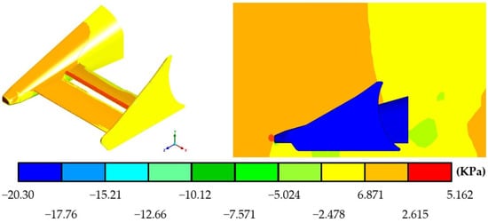
Figure 8.
Pressures produced by the air on the surface and the region around the MP4/4 front wing.
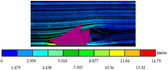
Figure 9.
Air speeds around the MP4/4 front wing.
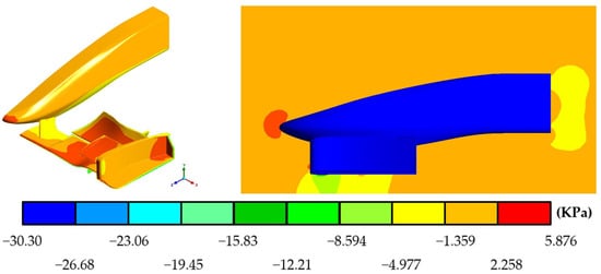
Figure 10.
Pressures produced by the air on the surface and the region around the FW31 front wing.
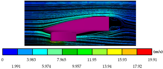
Figure 11.
Air speeds around the FW31 front wing.
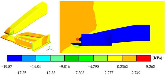
Figure 12.
Pressures produced by the air on the surface and the region around the W12 front wing.
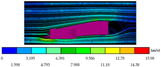
Figure 13.
Air speeds around the design based on the W12 front wing.
In addition to the pressure and speed results already presented, the software allowed us to obtain and analyze the results of the forces resulting from downforce and drag that acted on the front wings, and by applying these values to Equations (9) and (10), it was possible to calculate the aerodynamic coefficients for each front wing; the lift coefficient (CL) is presented with a negative value since it is the downforce coefficient, which is in the opposite direction of the lifting force.
These results are presented in Table 4, as well as a drag–downforce relationship that allowed us to know the efficiency of the interaction between these two forces.
Table 4.
Resultant forces and aerodynamic coefficients on the background front wings.
6. Results for New Front Wings
6.1. Aerodynamic Results
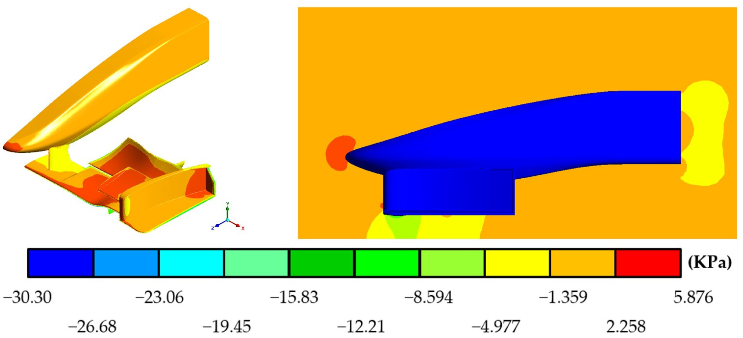
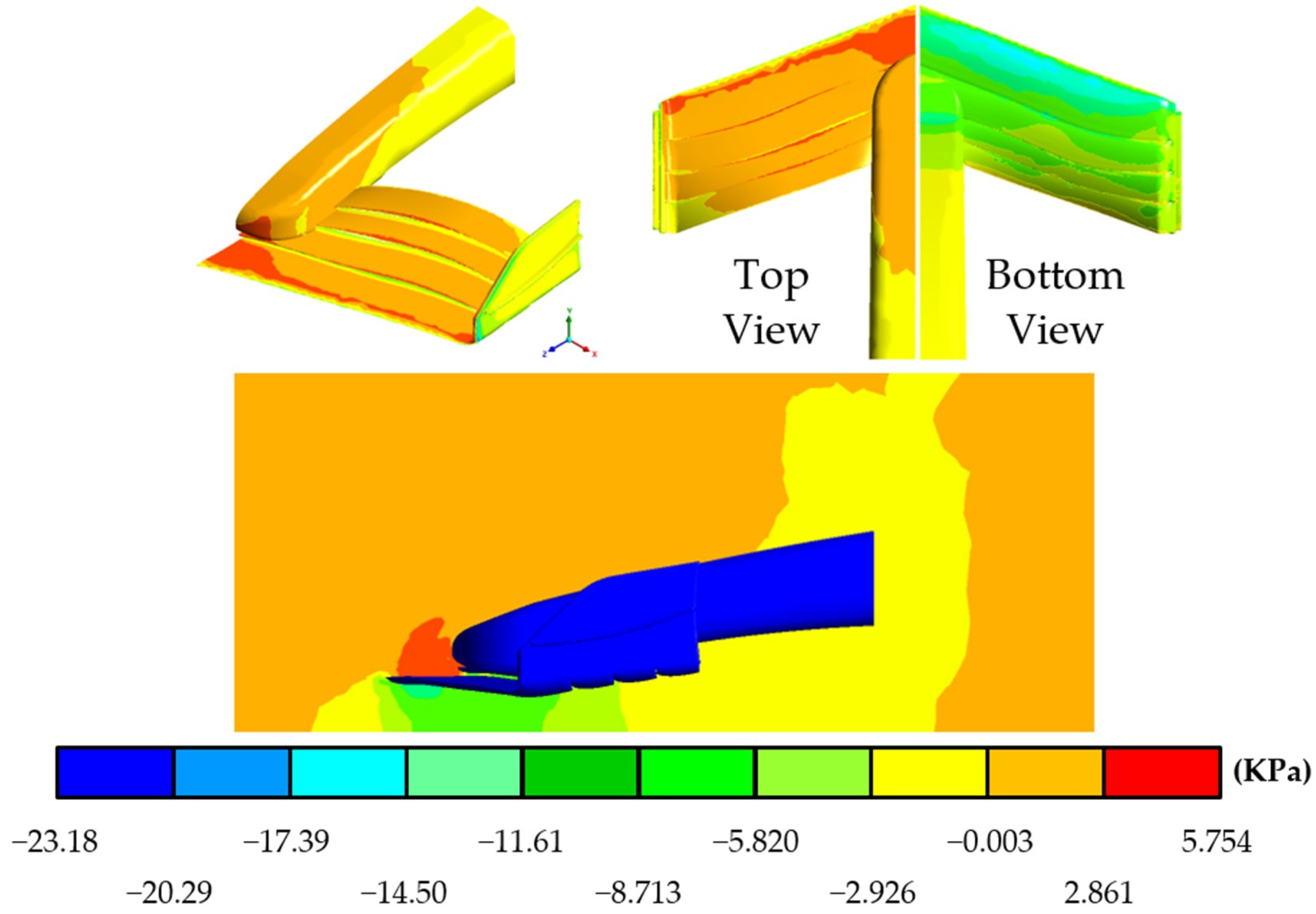
The results of the aerodynamic study, which included the variables of pressure on the surface and the air speed and pressure that circulates around the front wing, are presented below for the proposals MICC-75 (Figure 14 and Figure 15), CLV-54 (Figure 16 and Figure 17), and JJRC-10 (Figure 18 and Figure 19).
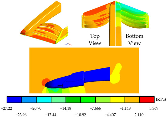
Figure 14.
Pressures produced by the air on the surface and the region around the MICC-75 front wing.

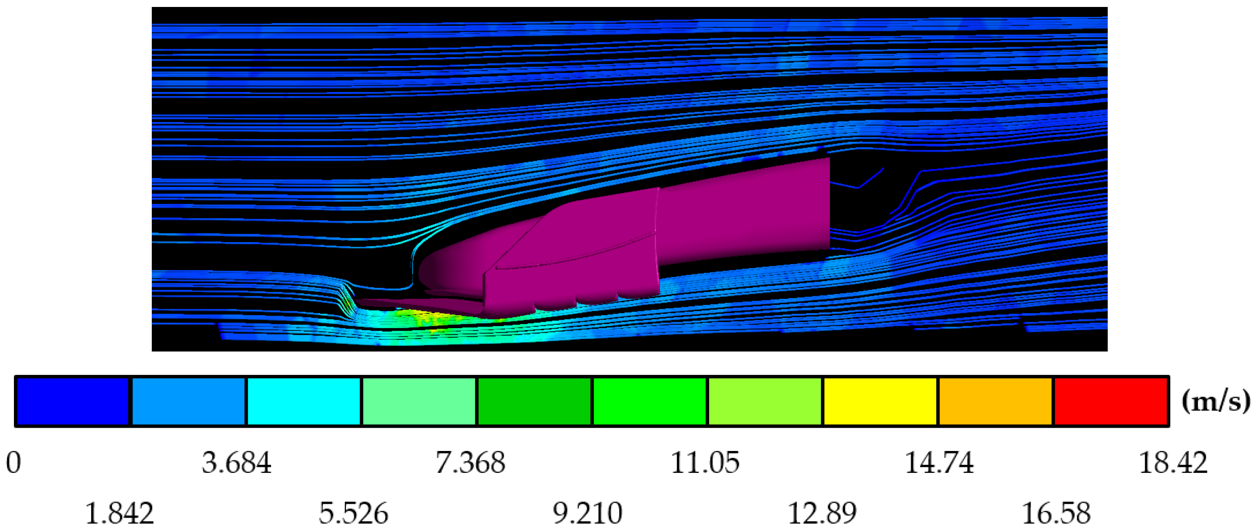
Figure 15.
Air speeds around the MICC-75 front wing.

Figure 16.
Pressures produced by the air on the surface and the region around the CLV-54 front wing.
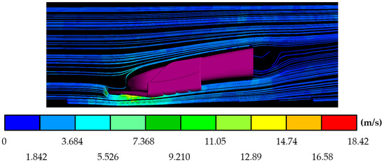
Figure 17.
Air speeds around the CLV-54 front wing.
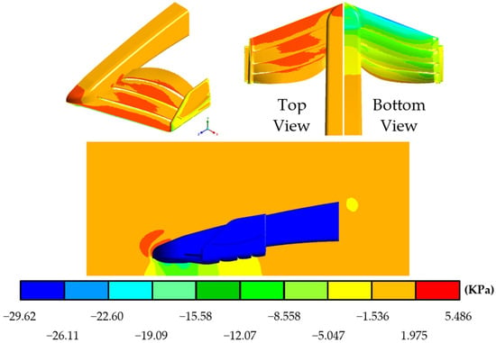
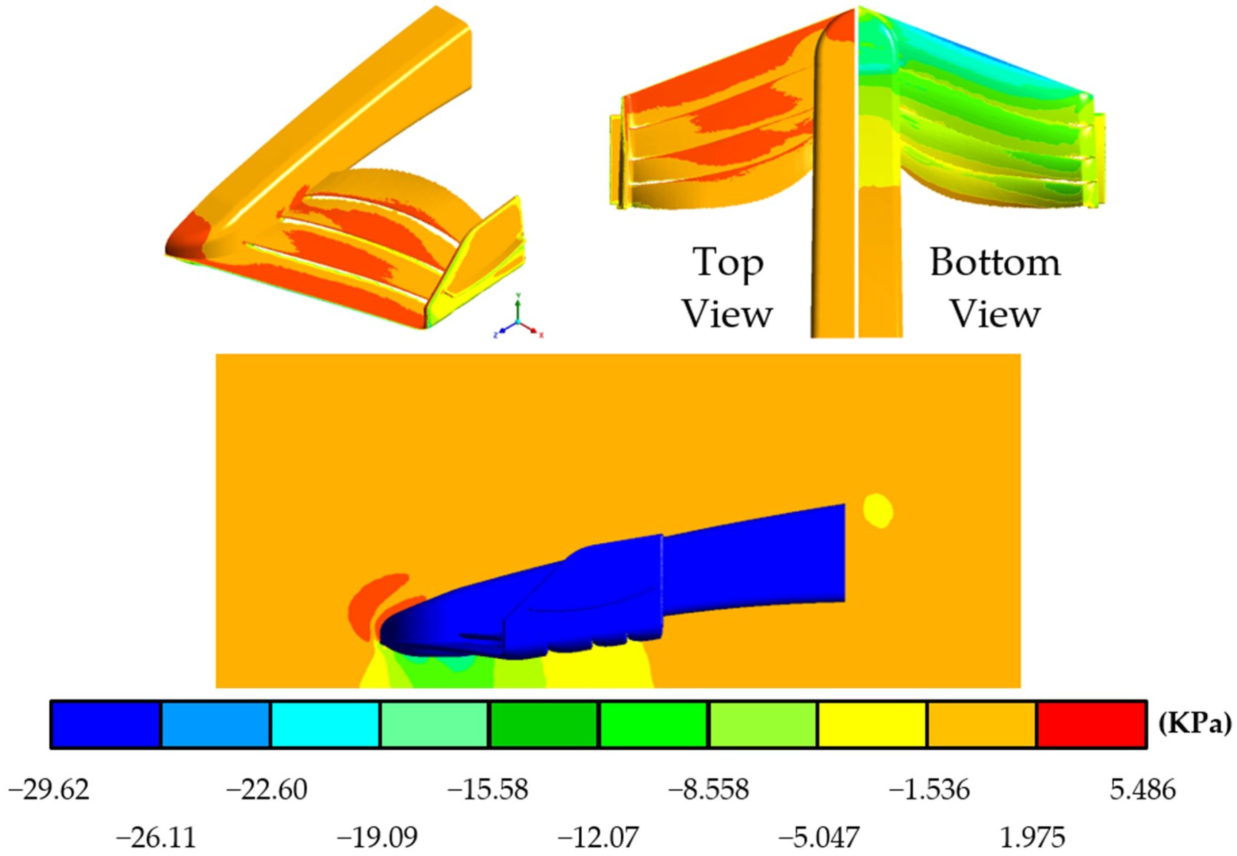
Figure 18.
Pressures produced by the air on the surface and the region around the JJRC-10 front wing.
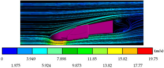
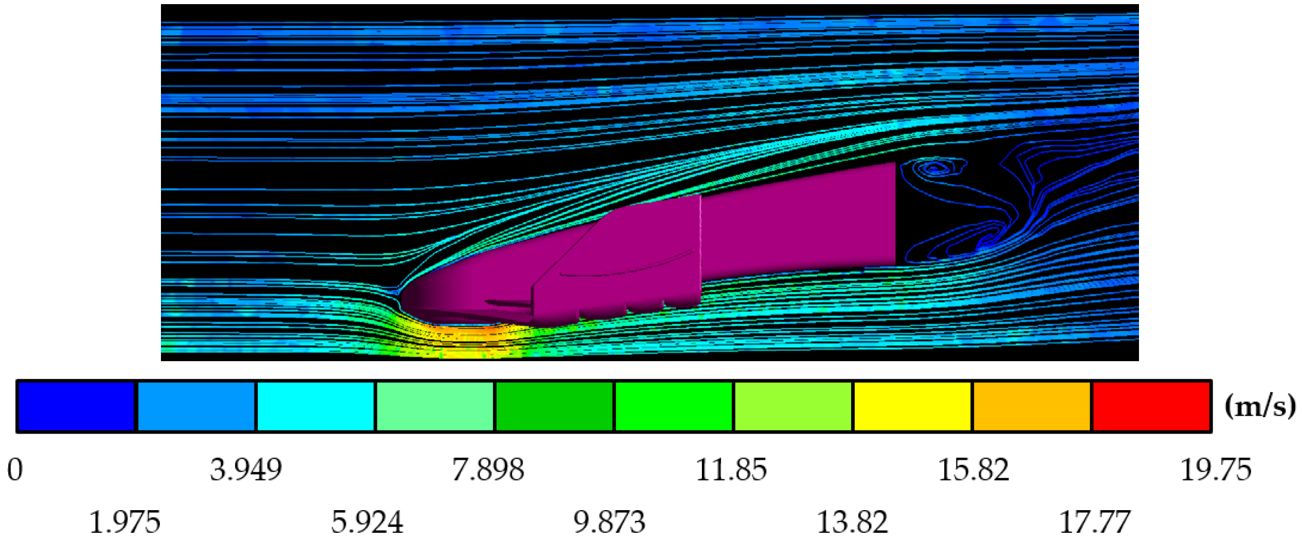
Figure 19.
Air speeds around the JJRC-10 front wing.
In the same way, in this series of simulations, it was possible to know the value of the aerodynamic forces that act on the front wings in critical conditions of maximum speed; the downforce and drag values for the designed proposals are specified in Table 5.
Table 5.
Resultant forces and aerodynamic coefficients on the new front wings.
6.2. Structural Results
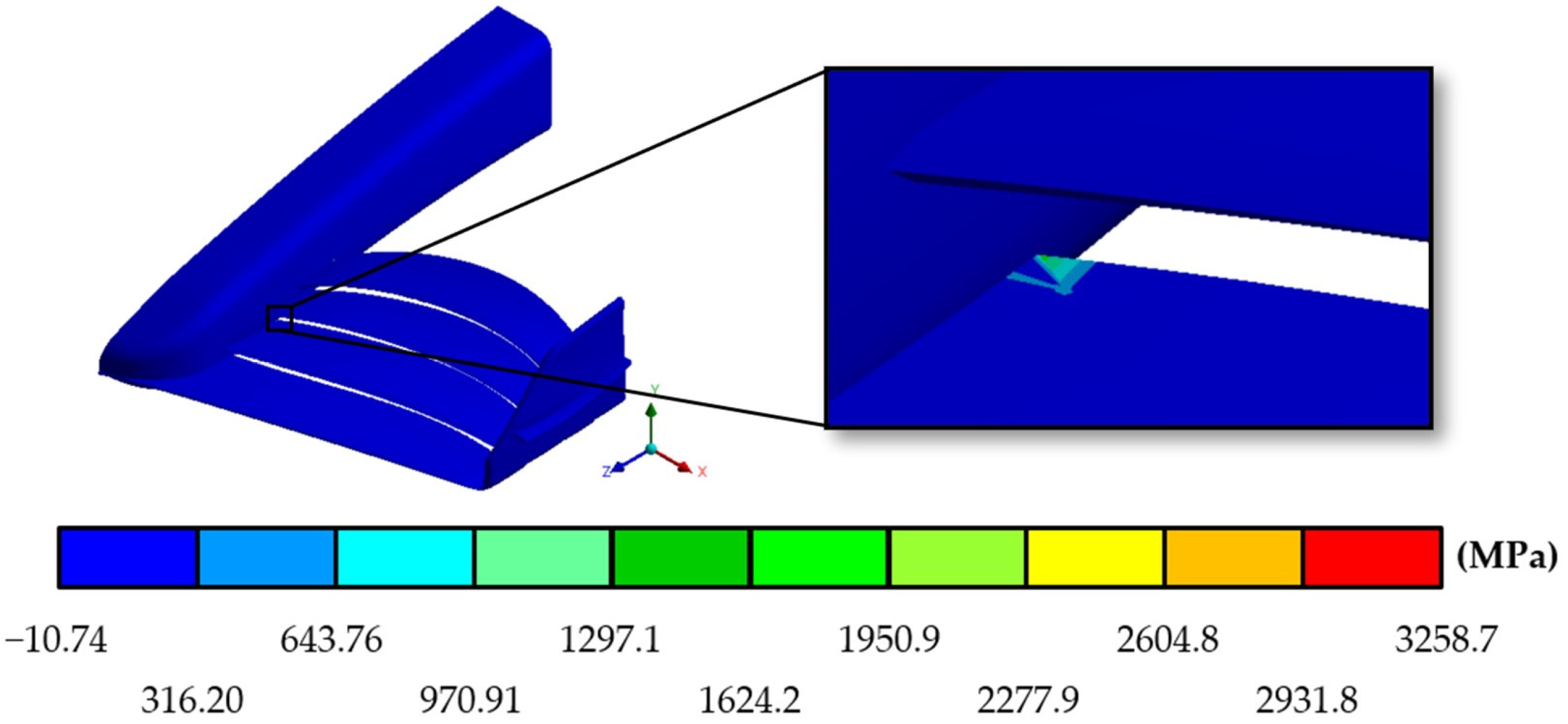
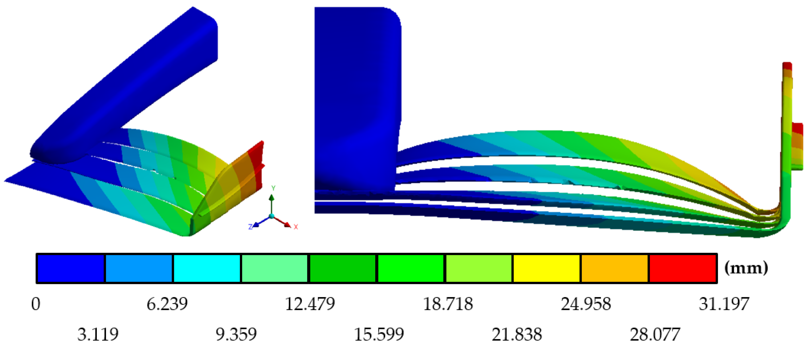
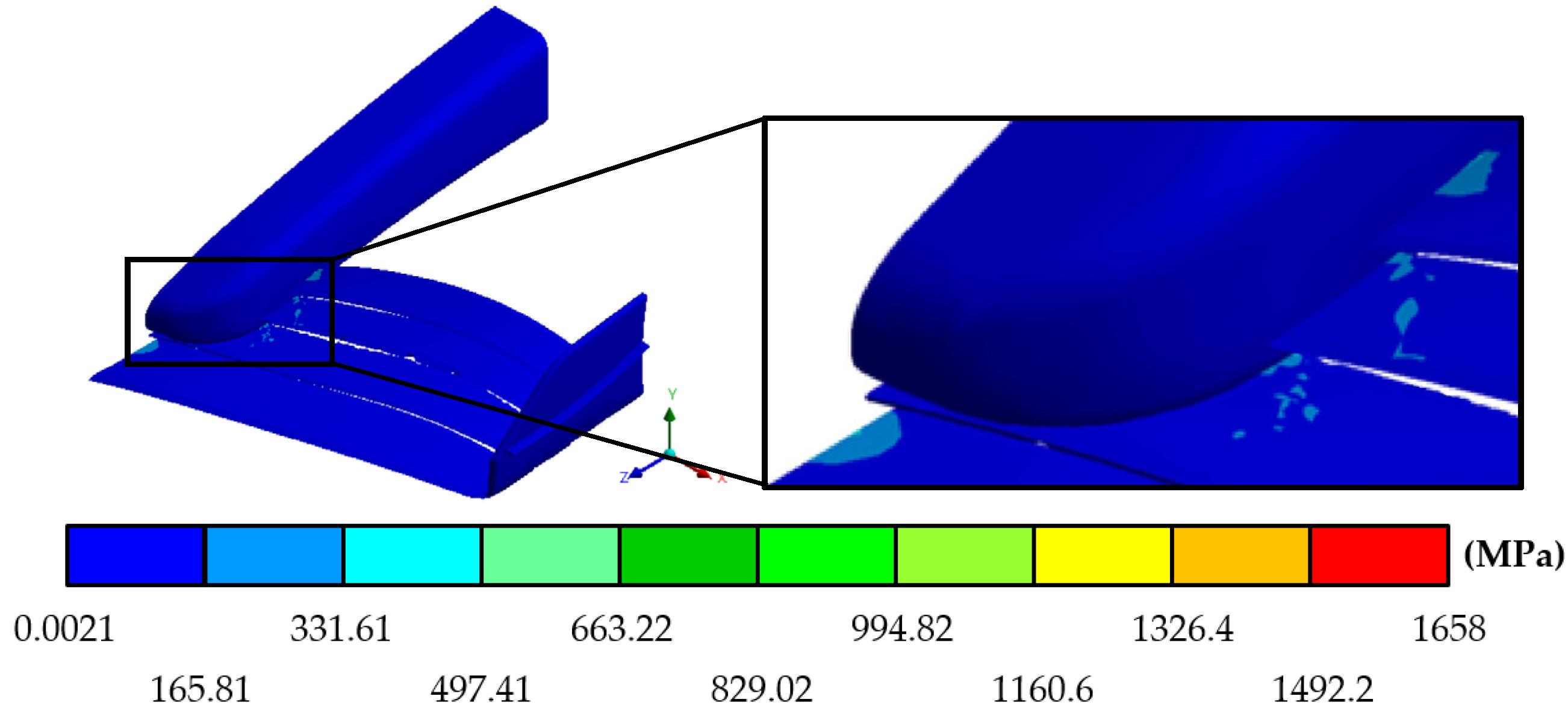
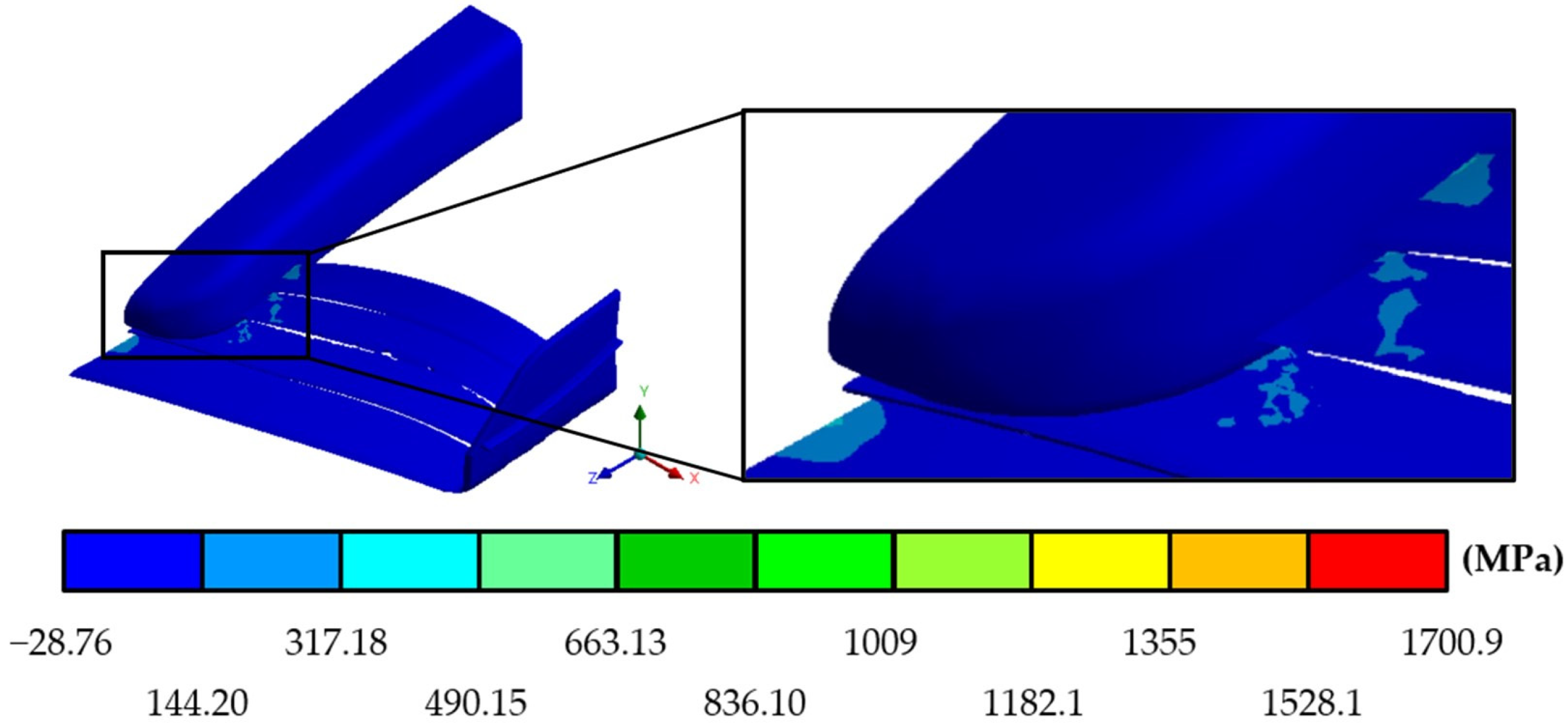
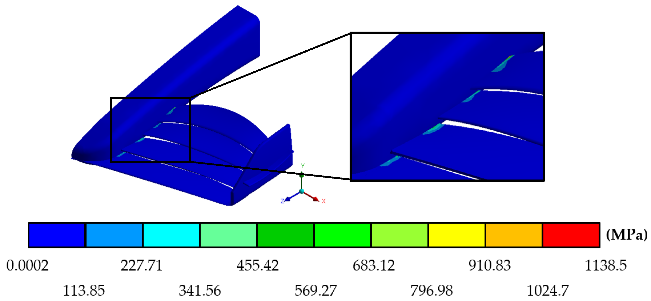
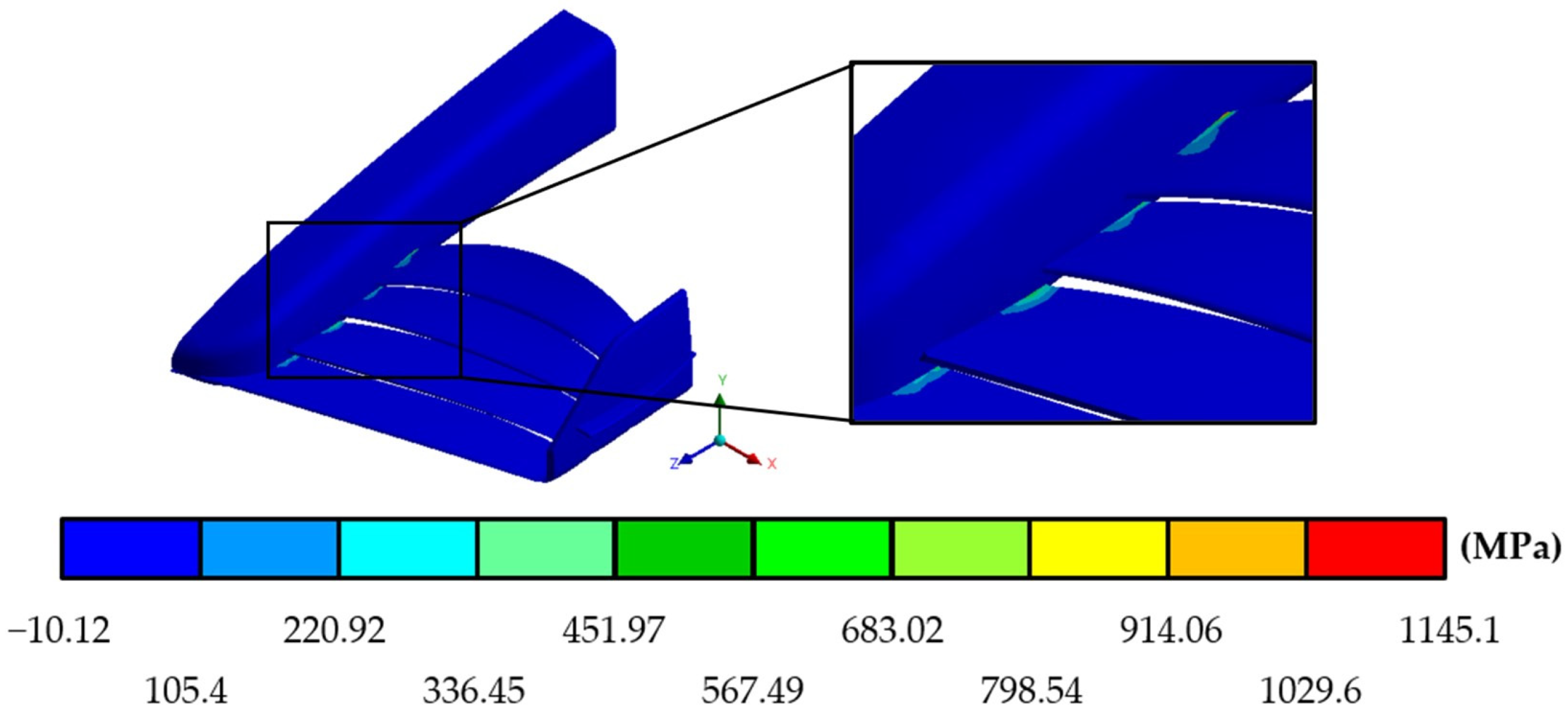
The results of the structural studies for the MICC-75 (Figure 20, Figure 21 and Figure 22), CLV-54 (Figure 23, Figure 24 and Figure 25), and JJRC-10 (Figure 26, Figure 27 and Figure 28) are presented below. They include the values of total deformation, Von Mises stress, and principal stress for each of the front wings.
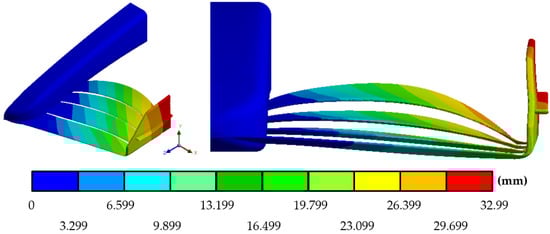
Figure 20.
Total displacements in the MICC-75.
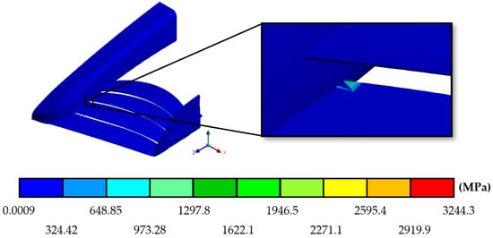
Figure 21.
Von Mises stress in the MICC-75.

Figure 22.
Maximum principal stress in the MICC-75.

Figure 23.
Total displacements in the CLV-54.

Figure 24.
Von Mises stress in the CLV-54.

Figure 25.
Maximum principal stress in the CLV-54.
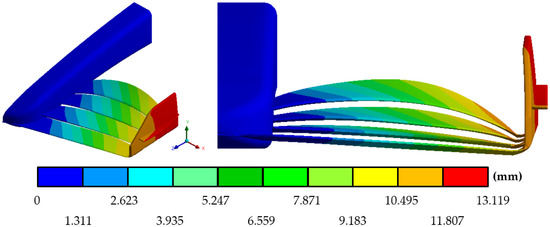
Figure 26.
Total displacements in the JJRC-10.
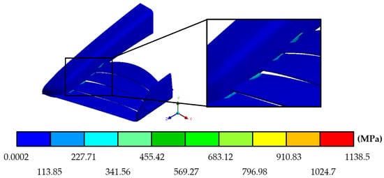
Figure 27.
Von Mises stress in the JJRC-10.

Figure 28.
Maximum principal stress in the JJRC-10.
Table 6 is presented below, condensing all the results obtained for the structural static simulation of the three proposals.
Table 6.
Summary of structural results for the three new front wings.
7. Experimental Study
7.1. Development of Wind Tunnel Test
To bring one of the three models to reality and to be able to carry out an experimental study in a wind tunnel, a comparison was made between the results obtained through simulations of the three proposals designed to select the best of these. By making this comparison with the results obtained from the static structural simulation, it was possible to ensure that the three front wings could fully operate under critical speed conditions, making them reliable under these working conditions and leaving them in equal conditions; that is why the selection criterion for the best proposal fell on the aerodynamic efficiency criterion, where despite presenting similar behaviors, the MICC-75 stood out for its low level of drag and the percentage it obtained in the drag–downforce ratio of only 8.636%, in addition to presenting a higher negative lift coefficient and a lower drag coefficient than the other proposals.
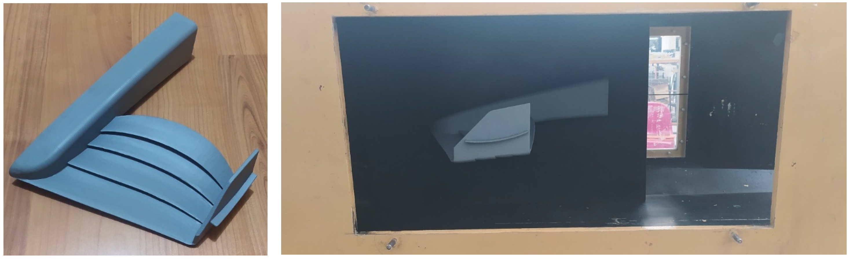
To carry out the experimental test, a prototype was made using 3D printing of the MICC-75; due to the size conditions of the wind tunnel where the test was carried out (Figure 29), it was necessary to modify the scale of the wing. Once the MICC-75 was printed, it was 28% of the size of the real front wing, achieving a blockage ratio value in the test section of the tunnel of 2.62%.

Figure 29.
MICC-75 prototype.
The wind tunnel of the Escuela Superior de Ingeniería Mecánica y Eléctrica (Superior School of Mechanical and Electrical Engineering) where the experimental study was carried out is an open-circuit wind tunnel, and the turbulence intensity of the inlet flow was 3%. The measuring devices for the aerodynamic forces that are installed in the tunnel can register variations of tenths of a Newton on the aerodynamic elements that are inside it, with an error rate of 5%.
Within this experimental study, three tests were conducted, with variations in the speed of the airflow for each test. The first test was carried out at 46.55 km/h; for the second test, the speed was 61.58 km/h; and in the last one, the test speed was 75.06 km/h. In the three tests, the values of the resulting aerodynamic forces on the front wing were measured. These forces were drag and downforce. Table 7 shows the measurements obtained from the experimental study, as well as the coefficients of negative lift and drag, where it can be seen how these were directly affected by the change in the Reynolds number, with an increase in the coefficient of negative lift and a decrease in the drag coefficient.
Table 7.
Resulting forces and aerodynamic coefficients on MICC-75 during experimental study.
7.2. Experimental Test Checking
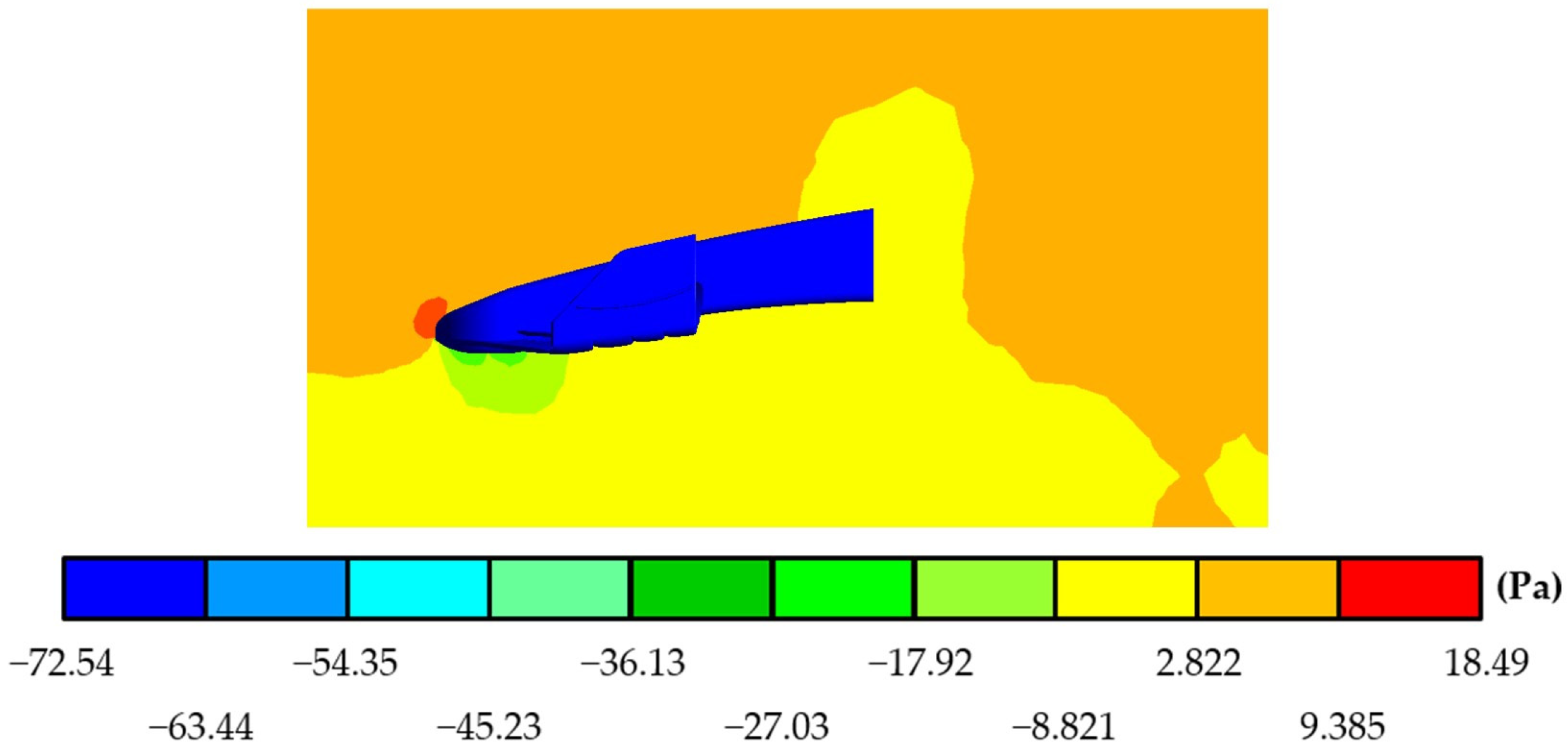
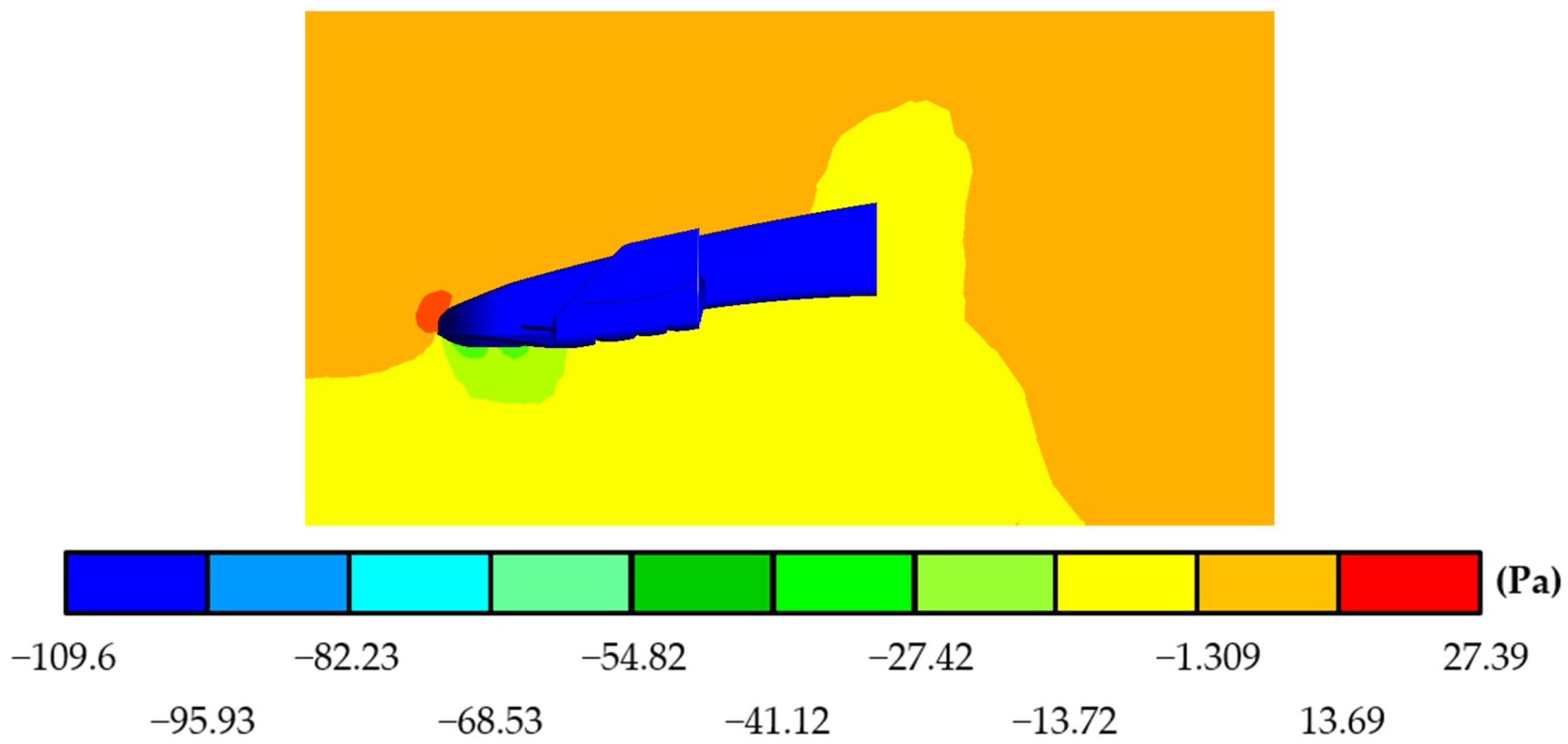
After carrying out the experimental test, a last series of numerical analyses were carried out using the Fluent tool of the ANSYS® Workbench software [18], fully replicating the conditions under which the experimental study tests were carried out; within the results, pressure behaviors around the MICC-75 were seen to be similar to those previously obtained during the three tests carried out at different speeds (Figure 30, Figure 31 and Figure 32).
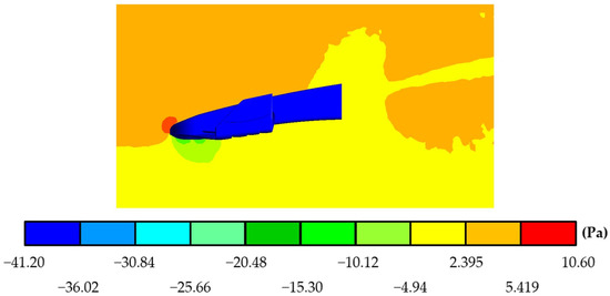
Figure 30.
Pressures exerted on the air around the MICC-75 during test 1.

Figure 31.
Pressures exerted on the air around the MICC-75 during test 2.

Figure 32.
Pressures exerted on the air around the MICC-75 during test 3.
Table 8 where they are also compared with the results obtained during the experimental study.
Table 8.
Comparison of resultant forces on the MICC-75.
8. Conclusions
Aerodynamic efficiency can be achieved through a relationship where the drag force is as small as possible compared to the downforce; this results in the vehicle being able to stay close enough to the ground without the disadvantage that the drag force compromises its speed by reducing it. The harmonious combination of these two forces that act on the single-seater allows for the creation of an efficient vehicle. Making a comparison between the three proposals presented and the 2021 season front wing based on the Mercedes-AMG W12 (which was part of the champion vehicle prior to the change in regulations), it can be seen that the proposals present better aerodynamic behavior and high efficiency, giving the car all the benefits to be able to function without failures.
The results obtained from the experimental test, together with the results of the simulations of this same test, are consistent, which serves to confirm that the numerical results obtained from the studies presented for the three proposals under critical conditions are correct.
Author Contributions
Conceptualization and methodology carried out by A.S.L.-C., G.U.-S. and B.R.-Á.; investigation performed by M.M.-M. and M.A.G.-L.; numerical analysis and modeling performed by A.S.L.-C. and M.I.C.-C.; resources provided by G.U.-S. and G.M.U.-C.; prototype developed by M.M.-M., M.A.G.-L. and D.M.-A.; experimental study conducted by A.S.L.-C., M.I.C.-C. and D.M.-A.; writing, review and editing by A.S.L.-C. and G.U.-S.; supervision to the whole research provided by B.R.-Á. and G.M.U.-C.; project administration by A.S.L.-C. and G.U.-S. All authors have read and agreed to the published version of the manuscript.
Funding
This research was funded by the Dirección de Investigación and Secretaría de Investigación y Posgrado at Instituto Politécnico Nacional (IPN).
Institutional Review Board Statement
Not applicable.
Informed Consent Statement
Not applicable.
Data Availability Statement
Not applicable.
Acknowledgments
The work team wants to thank the Instituto Politécnico Nacional (IPN) and Consejo Nacional de Humanidades Ciencia y Tecnología (CONAHCYT).
Conflicts of Interest
The authors declare no conflict of interest.
References
- Hitchens, F.E. The Encyclopedia of Aerodynamics; Andrews UK Limited: Luton, UK, 2015; pp. 42–43. [Google Scholar]
- McBeath, S. Aerodinámica del Automóvil de Competición; CEAC, 2005; pp. 17–27. Available online: https://pdfcoffee.com/simon-mcbeath-aerodinamica-del-automovil-de-competicion-ceac-2005-pdf-free.html (accessed on 23 May 2022).
- Castro, X.; Rana, Z.A. Aerodynamic and Structural Design of a 2022 Formula One Front Wing Assembly. Fluids 2020, 5, 237. [Google Scholar] [CrossRef]
- Anderson, J.D. Fundamentals of Aerodynamics; McGraw-Hill: New York, NY, USA, 1991; pp. 15–18. [Google Scholar]
- Isidoro-Carmona, A. Aerodinámica y Actuaciones del Avión, 10th ed.; Paraninfo: Madrid, Spain, 2015; pp. 80–91. [Google Scholar]
- Fédération Internationale de l’Automobile. 2022 Formula One Technical Regulations; Num. 10; Fédération Internationale de l’Automobile: Paris, France, 2022. [Google Scholar]
- Dominy, R.G. Aerodynamics of Grand Prix cars. Proc. Inst. Mech. Eng. Part D J. Automob. Eng. 1992, 206, 267–274. [Google Scholar] [CrossRef]
- Diasinos, S.; Barber, T.; Doig, G. Numerical analysis of the effect of the change in the ride height on the aerodynamic front wing–wheel interactions of a racing car. Proc. Inst. Mech. Eng. Part D J. Automob. Eng. 2017, 231, 900–914. [Google Scholar] [CrossRef]
- Gaikwad, V.; Ugale, A.S. Overview of Active Suspension System. Int. Res. J. Eng. Technol. 2020, 7, 759–763. [Google Scholar]
- Yin, H.T.; Lang, M.M.; Zhao, Y.N. Research on Carbon Fiber Composite Materials and F1 Racing Automobile Design. Appl. Mech. Mater. 2014, 454, 263–267. [Google Scholar] [CrossRef]
- Hutton, R. Fédération Internationale de l’Automobile Centenary; Fédération Internationale de l’Automobile: Paris, France, 2004; pp. 122–123. [Google Scholar]
- Wolf, T. The Aerodynamic development of the new Porsche Cayenne. Proc. Inst. Mech. Eng. Part D J. Automob. Eng. 2019, 234, 390–408. [Google Scholar] [CrossRef]
- Skiba, Y.N. Introducción a la Dinámica de Fluidos; Universidad Autónoma de México: Mexico City, Mexico, 2009; pp. 34–49. [Google Scholar]
- ANSYS Inc. ANSYS Fluent User’s Guide; ANSYS Inc.: Canonsburg, PA, USA, 2013; pp. 505–512.
- Huang, T.; Zhuang, X.; Wan, Z.; Gu, Z. Experimental and numerical investigations of the vehicle aerodynamic drag with single-channel rear diffuser. Proc. Inst. Mech. Eng. Part D J. Automob. Eng. 2020, 234, 2216–2227. [Google Scholar]
- Wang, Y.N.; Tseng, C.Y.; Huang, Y.L.; Leong, J.C. Investigation of 2004 Ferrari Formula One Race Car Wing Effects. In Proceedings of the 2010 International Symposium on Computer, Communication and Autoation, Tainan, Taiwan, 5–7 May 2010; pp. 85–88. [Google Scholar]
- Çengel, A.Y.; Cimbala, M.J. Mecánica de Fluidos; Fundamentos y Aplicaciones, 1st ed.; McGraw-Hill: New York, NY, USA, 2006; pp. 561–601. [Google Scholar]
- Sharma, R.B.; Bansal, R. CFD simulation for flow over passenger car using tail plates for aerodynamic drag reduction. IOSR J. Mech. Civ. Eng. 2013, 7, 28–35. [Google Scholar] [CrossRef]
- International Journal of the FIA. The old one-two. Auto Mag. 2014, 9, 74–75.
- Rendle, S. McLaren MP4/4 1988; Owner’s Workshop Manual; Haynes: Sparkford, UK, 2018. [Google Scholar]
- Williams FW31 Specifications, F1 Technical Database. 2021. Available online: https://www.f1technical.net/f1db/cars/951/williams-fw31 (accessed on 15 November 2021).
- F1 W12 E Performance. Mercedes-AMG Oficial WebSite. 2021. Available online: https://www.mercedesamgf1.com/news/introducing-w12-the-mercedes-f1-challenger-for-the-2021-season (accessed on 18 November 2021).
- Pina-Macedo, A. Modelización de Problemas de Interacción Fluido-Estructura con Elementos Finitos de Orden Elevado. Bachelor’s Thesis, Escuela Técnica Superior de Ingeniería, Universidad de Sevilla, Seville, Spain, 2015; pp. 1–34. [Google Scholar]
- Airfoil Tools. Airfoil Database Generator; Airfoil Tools: 2022. Available online: http://airfoiltools.com (accessed on 23 May 2022).
- Fédération Internationale de l’Automobile. 2021 Formula One Technical Regulations; Num. 10; Fédération Internationale de l’Automobile: Paris, France, 2021. [Google Scholar]
- Freitag, W.; Terry-Schulze, E. Blended Winglets Improve Performance. Aeromag. Boeing 2009, 35, 9–12. [Google Scholar]
- Heide, J.; Karlsson, M.; Altimir, M. Numerical Analysis of Urea-SCR Sprays under Cross-Flow Conditions; SAE Technical Paper 2017-01-0964; SAE: Warrendale, PA, USA, 2017. [Google Scholar]
- Srividhya, S.; Nehru, K.; Subramanian, M. Fluid-Structure Interaction Study on an Aircraft wing model using ANSYS Coupling system. Int. J. Eng. Res. Appl. 2020, 10, 21–32. [Google Scholar]


Disclaimer/Publisher’s Note: The statements, opinions and data contained in all publications are solely those of the individual author(s) and contributor(s) and not of MDPI and/or the editor(s). MDPI and/or the editor(s) disclaim responsibility for any injury to people or property resulting from any ideas, methods, instructions or products referred to in the content. |
© 2023 by the authors. Licensee MDPI, Basel, Switzerland. This article is an open access article distributed under the terms and conditions of the Creative Commons Attribution (CC BY) license (https://creativecommons.org/licenses/by/4.0/).