Article

Experimental Analysis of a Cracked Cardan Shaft System under the Influence of Viscous Hydrodynamic Forces

by
Bernard Xavier Tchomeni Kouejou
* and
Alfayo Anyika Alugongo
Department of Industrial Engineering, Operation Management, and Mechanical Engineering, Vaal University of Technology, Andries Potgieter Blvd, Private Bag X021, Vanderbijlpark 1911, South Africa
*
Author to whom correspondence should be addressed.
Fluids 2023, 8(7), 211; https://doi.org/10.3390/fluids8070211
Submission received: 8 June 2023 / Revised: 10 July 2023 / Accepted: 15 July 2023 / Published: 18 July 2023
(This article belongs to the Special Issue Wavelets and Fluids)

Abstract

:
Accurate prediction of the dynamic behavior of coupled shafts in a fluid medium is crucial to accurately estimate equipment life and enable safe operation. However, this task is far from trivial due to the vibrations induced by the highly nonlinear nature of the machine system. This paper presents an experimental analysis of a cardan shaft under the influence of viscous hydrodynamic forces. An experimental setup was created using a cardan shaft rig installed in a plexiglas tank, with a self-aligned crack simulator supporting the driveshaft for crack extraction. Adequate instrumentation was used to measure the rotor’s fluctuation under industrial viscous fluid at various motor speeds. By analyzing the changes of unwanted high vibration, the obtained results demonstrated that the characteristics of the cracks in the fluid medium can be efficiently extracted from multiple tests using the wavelet synchrosqueezing transform and energy spectrum. This latter aspect, in particular, implies that the responses that can be observed in practice are highly sensitive to the values of the system parameters: average flow velocity, mass eccentricity, and shaft stiffness, among others. Finally, the study provides conclusions on practical applications for the reliable identification of cracks in a viscous fluid to validate the recently published theoretical study.

1. Introduction

Mechanical systems consisting of a Hooke joint (also known as a universal joint or universal joint) are, by design, built for tight spaces in marine propulsion systems that are not easily accessible. The cardan shaft is a common mechanism used in rotating machinery to transmit motion from the driveshaft to the whole system. The cardan shaft connects the driveshaft to a power source and to the driven component, transferring rotational motion and torque as the driveshaft rotates. It has a wide range of activities in the mechanical industry and vast applications in the automotive sectors to transmit rotary motion. The classical design of the cardan shaft is constituted by a series of one or two Hooke’s joints and reciprocally connected with a shaft that ordinarily facilitates an axial dilatation. Dynamic analysis and efficient fault prediction of such systems in modern machinery are becoming progressively significant due to the increasing tendency to combine high rotation speed with more slender and lighter machine elements. The connection between parallel rotating shafts is a common and essential rotor problem. The shaft system corresponding to a parametrically excited one possesses several specific resonance conditions. Unfortunately, maintenance of universal joint shafts is often difficult due to their size, function, and accessibility, making their alignment one of the most often overlooked and misunderstood issues an operator can encounter. Condition monitoring of interconnected engineering systems has attracted the interest of many researchers. Investigators have focused on various techniques based on vibration analysis for health monitoring of damage in the system [1]. Once the idea of isolating the driving and driven mechanisms with isolated shafts developed, coupling issues arose. Subsequently, numerous methods for joining these shafts came into involvement. The Hooke’s joint, among others, is one of the sensitive motion transmission components in automotive and turbomachinery design and has a significant impact on the system response [2]. Early reports in [3,4] demonstrated that vehicle machine testing revealed that 14% of mechanical transmission failures are caused by universal joints, with U-joints accounting for approximately 60% of failures. Industrial applications that work with substantial torque loads require maximum strength and durability of the universal joint components. The recent universal joint has become more complicated than its simple ancestor, due to its increased performance and ability to handle greater operating angles, more sophisticated universal joint designs such as constant velocity (CV) have replaced Hooke’s joint in more demanding applications such as automotive transmissions and industrial machinery [5]. The trend to build larger and higher-speed drive mechanisms has contributed to increasing coupling problems. To address the challenges associated with angular misalignment, research into angular joint misalignment has focused on improving joint design for the transmission of motion. Such system characteristics are significant due to the increasing tendency to design more slender and lighter machine elements, generally combined with high rotation speed in modern machinery [6]. One of the fundamental problems in the vibration monitoring of the cardan shaft is its inaccessibility during the operation of the machine to detect possible malfunctions and monitor their evolution for mechanical intervention. This continuous monitoring avoids frequent stops leading to a repeated passage at resonant frequencies, favoring the phenomenon of cracking. Numerical modeling methods have then constituted an interesting alternative to feedback, making it possible to study the impact of a crack on the vibration behavior and verify the relevance of the descriptors used by the monitoring systems. Nevertheless, in practice, the exceptional nature of rotor cracking phenomena makes it difficult to evaluate the reliability of the algorithms developed specifically for their detection and whose validation by experimental models is often delicate and capital-intensive. Dupal and Zajicek [7] have shown that the primary goal of evaluating such systems is the analysis of the instability conditions as well as the periodic solution of the steady-state motion. In the shafts interconnected by a Hooke’s joint, the driveshaft may undergo vibration due to parametric excitations and lead the system to experience dynamic parametric resonance. A restricted experimental study was carried out to explore the failure of the cardan shaft resulting from a transverse crack. The work of [8] presented a state estimation method using ensemble empirical mode decomposition to identify the operating state of a cardan shaft in high-speed trains by collecting two sets of gearbox vibration signals. Most studies have concentrated on the behavior of mechanisms coupled to universal joints [9,10,11,12,13]. However, there have been many cases of failure associated with the malfunctioning driveshaft in practice, and a limited article can be found that addresses this specific topic of cardan shaft failure in a fluid medium [5,14].
The recently published numerical study of this model concluded that the vibration generated by Hooke’s joint and the strong fluctuation of the connected rotors are proportional to the transient stiffness of the flexible drive shaft [4,5,6,7,8,9,10,11,12,13,14,15]. In the present experimental study of a cracked driveshaft interconnected via Hooke’s joint, it is important to consider the effect of fluid properties, shaft geometry, and speed. The technical novelty of a cracked cardan shaft partially immersed in the fluid would be the study of the effects of the combined influence of a crack and viscous hydrodynamic forces on the shaft’s performance and behavior. Hydrodynamic forces arise when the fluid film exerts a dynamic influence on the lateral motion of the shaft. These whirling forces, influenced by factors such as fluid viscosity, shaft speed, and geometrical properties of the disc, cause the shaft to deflect in a circular motion. The viscous hydrodynamic forces generated by the viscous fluid partially immersing the shaft will add additional complexity to the behavior of the crack, which in turn can affect the vibration and stability of the shaft [15]. This is different from the traditional study of a shaft under only mechanical loads or only under viscous hydrodynamic loads. Additionally, the study of the interaction between the crack and the viscous fluid flow can provide new insights into the crack’s behavior and can provide a better understanding of the crack’s behavior in real-world applications where the shaft is partially immersed in a viscous fluid or other fluid. This can be useful for improving the design and maintenance of mechanical systems that use cardan shafts, especially those that operate in environments where they are partially submerged in water. As the effects of noise obstruct the signal system, the other contribution of analyzing a cracked cardan shaft partially immersed in a viscous fluid is the application of an advanced signal processing technique such as wavelet synchrosqueezing to extract detailed information about the shaft’s behavior, including the location and amplitude of specific frequency components. The results of the current experimental study will be further connected with those of the numerical simulations because the aforementioned technique was analytically applied in a recently published publication [15].
The remainder of this paper is organized as follows: Section 2 presents the description of the experimental setup and the experimental results for validation of the simulated response. Section 3 shows the experimental results obtained using the proposed dynamic model under fluid force conditions and the detailed analyses related thereto. A specific industrial GST 32 viscous oil is utilized to control the unwanted vibration of Hooke’s joint with a crack. In Section 4, a brief discussion of the methods developed for crack identification in a viscous fluid using a synchrosqueezing technique is addressed. Finally, Section 5 concludes the paper, highlighting the main findings of the present work and its limitations.

2. Experimental Description of the Coupled Shaft System

2.1. Description of the Cardan Shaft Setup

In this experimental study, the Hooke’s joint manufactured by SKF Group materials and modified Rotor-Kit 4 Bently Nevada benchmarks for various tests as presented in Figure 1 will be used. The set-up, as shown in Figure 1b, consists of a driveshaft connected to an AC motor and transmitting its motion to a driven shaft supported by four self-aligned bearing systems. The driveshaft is connected to an AC motor (maximum speed: 10,000 rpm and 75 W DC) and transmits its motion to a driven shaft supported by four self-aligned bearing systems. Each shaft carries a disk with an inside diameter of 10 mm, an outside diameter of 75 mm, and a thickness of 25 mm with a mass of 0.845 kg, mounted at a position 290 mm from the right end of the rotor. An unbalance is created in both shafts by fitting a small mass of 0.018 kg to a point on the disc 10 mm from the circumference of the shaft. Self-aligning bearings are used to accommodate minor angular deviations without damaging the bearing surfaces and to accommodate misalignment between the shaft and the bearing housing, as shown in Figure 1a. The distance between the centers of Hooke’s joints of both shafts is 570 mm. The articulation angle of the cardan shaft was adjusted to a maximum angle of 7 degrees to limit high excitation. The important preparation for the experiment was to first create the transverse breathing crack on the driveshaft. As explained by Sabnavis et al. [16], most experimental studies are focused on open cracks (called notches or gaping cracks) because this crack type is easy to mimic in a laboratory environment. However, in this study, the transverse open and close crack (breathing) has been chosen as the type of crack, and its opening and closing behavior is controlled by a crack simulator as shown in Figure 2c.
A precrack of the shaft was first machined on a wire-cut machine, and then the shaft was used to conduct a fatigue experiment on a bending-torsion fatigue experiment on a fatigue bending. Therefore, a cracked driveshaft whose crack more closely resembled the real crack of practical engineering was obtained. Thus, the crack simulator composed of four orthogonal internal springs was positioned at the midspan of the driveshaft, and the breathing mechanism was created by tightening or loosening the threaded nut attached to the simulator casing and adding cyclic loading discs to the driveshaft at the slit location (Figure 2d). The 12 mm SealMaster MSF-27 flanged bearing with a 4-bolt flange and square flanges was chosen and installed on a plexiglas to facilitate the transmission of motion with minimum friction without compromising the dynamic characteristics of the rotor. The selected mechanical seals shown in Figure 2a facilitated the changing of healthy and defective shafts without affecting their sealing performance over an extended period of operation.
Secondly, the test rig is also constituted of a transparent plexiglas-made rectangular reservoir with an internal dimension width of 0.75 m, a height of 0.5 m, and a breadth of 0.1 m was installed through the Rotor Kit-4. The choice of the tank’s internal size was made so that the tank breadth was more significant than the boundary layers of the tank walls. In this experiment, the reservoir was filled with a light viscosity GST Oil 32 (Chevron) for a heat engine due to its valuable viscous properties. Hydrodynamic force sensors are attached under the rotor case pedestals by bolts, and the accelerometer sensor is installed on the platform by a screw thread. The speed of the motor could be varied by means of the field current control. The adjustment of the distance between the free surface of the fluid and the bottom of the container is in the order of the average thickness (h = 0.5 m) of the fluid. The experimental tests were conducted through two scenarios without viscous fluid around the misaligned shaft and with hydrodynamic force surrounding the driveshaft. For this purpose, a coupling joint representing the misalignment of the cardan shaft was used to connect shafts in the experimental set-up shown in Figure 1.

2.2. Measurement and Structural Adjustments

In this practical analysis, the measurement accuracy is maintained by considering the calibration of the sensors, the suppression of parasitic oscillations of the supports with additional vibration attenuators (rubber), and the verification of no parallelism between the shafts. To improve the rigidity of the lower support and reduce or eliminate the parasitic oscillations recorded at the end, the upper part of the reservoir containing the fluid is open. The displacement sensor has been designed to measure a maximum displacement of ±1 mm in the horizontal and vertical directions and has been carefully calibrated. Six proximity probes arranged both horizontally and vertically were used to provide the vibration readings. To ensure that the sensors are securely connected to the shaft support and can collect correct vibration data, measurement set-up, and mounting techniques are taken into consideration. They are positioned as shown in Figure 2c, 440 mm (support S3) from the left end of the motor, 70 mm (support S1) from disc 1, and 210 mm (support S2) from disc 2. Supports S1 and S3 are close to the left and right supports, respectively, while S2 is close to where the crack is. The type of defect and the measurement objectives required will determine the precise location of vibration measurements on a cracked shaft. In this case, measurements are made near crucial points along the shaft to correctly capture the relevant vibration signals and the position of the crack where significant crack-induced vibrations are anticipated. As the presence of viscous fluid’s load increases the motor torque to a maximum constant value keeping the mechanical power constant, and the speed of the motor decreases. Therefore, the experiments in a viscous fluid are performed at a lower motor speed. To ensure the reliability of this experiment and make sure that the outcomes are significantly more accurate and reproducible, a long period of rest was observed before and between tests to allow the self-evacuation of air bubbles and the collection of motor speed using the laser tachometer as shown in Figure 1c. The results obtained validate the procedure developed for the experimental trials. To successfully process and evaluate the recorded vibrations, it is essential to apply the appropriate signal conditioning and data collection methods to effectively process and evaluate the recorded vibrations. Accordingly, the probes are connected to the Ascents 2011 data acquisition instruments, the information is then transferred from the SCOUT Pro data acquisition system to the PC for signal processing using MATLAB software 2022 (Figure 2b).
The Ascent data acquisition system recorded both the excitation force and the vibration response of the twin-rotor measured by the stainless-steel probe sensors at some specific points along the driveshaft axis. The running speed of the Rotor Kit is 1500 rpm, so the rotation frequency is 25 Hz. The sampling frequency is 1200 Hz, and the sampling points are 1920. The simulation and experimental tests were conducted in two scenarios without viscous fluid around the misaligned shaft and with the driveshaft’s hydrodynamic force. For this purpose, the performed analysis with the physical and geometric properties listed in Table 1 and Table 2 was used to study the viscous fluid’s influence around the cracked driveshaft system.

3. Results and Discussion on the Balanced Rotor System

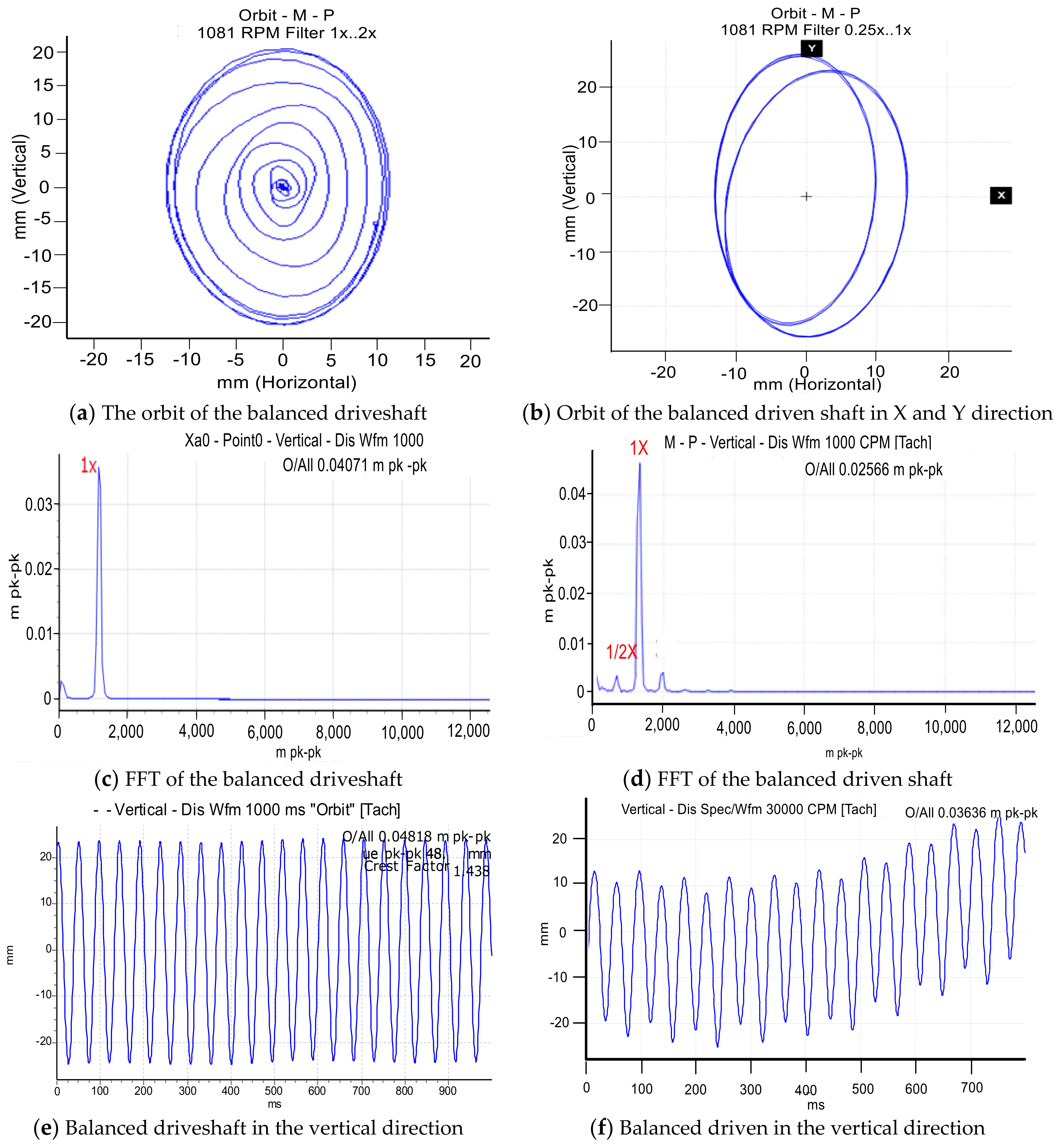
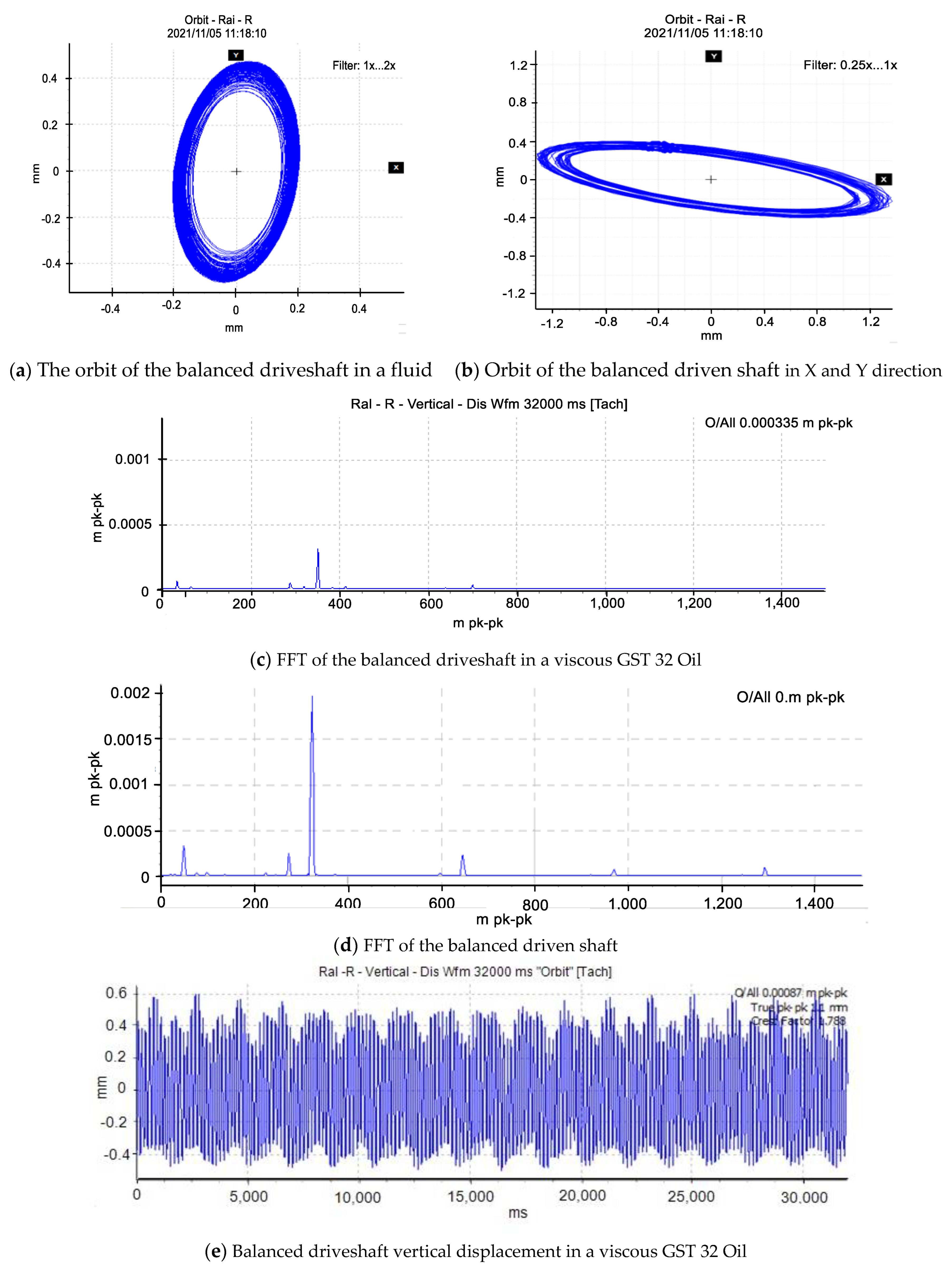
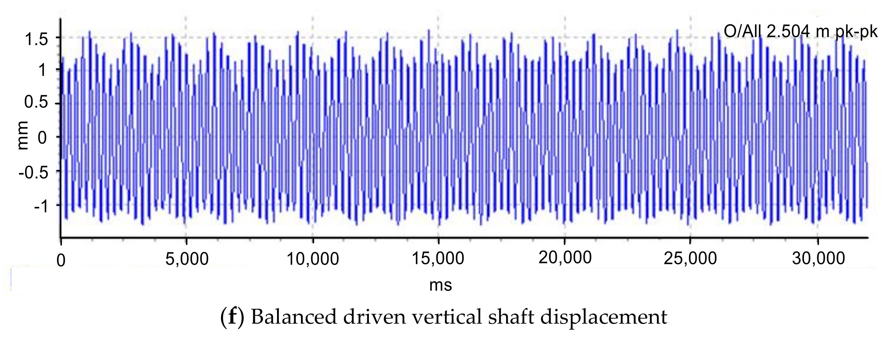
3.1. Baseline Test Results

Preliminary analysis of balanced driveshaft vibration at variable angular velocity for driven shaft angular velocity fluctuation has been previously published in [10,11,12] using Fast Fourier Transform (FFT), orbit disturbance, and lateral displacement of misaligned shafts. This work will compare healthy and cracked shaft diagrams operating under the influence of a viscous fluid through the spectrum plot response. Experimental tests were carried out on cracked and healthy cardan shafts, where the sampling frequency was 1600 Hz, and the data acquisition time for each test was set up to 120 s to acquire sufficient data for effective analysis. The rotor started to turn and stabilize gradually at 1500 rpm during each test. Vibration readings of the cracked driveshaft were performed in lateral displacement, frequency spectrum, and orbits with a maximum driveshaft vibration. Overall selected plots are displayed within this work for ease of reading and effective comparison.
Figure 3 shows the vibration results of balanced rotors passing their first critical speed under normal conditions at low motor speed to avoid coupling joint excitation. Figure 3c,d shows that without fluid, only 1× revolution speed and natural system frequencies are present in lateral and rotational displacement. The presence of a small 1/2× subharmonic and a super-harmonic frequency component near the first critical speed can indicate a transmission fault. These fluctuations in transfer speed result in harmonies centered on the fundamental frequency, indicating a connection fault. Orbital patterns of the balanced rotors of both rotors passing through their first critical speed are regular circular shapes, Figure 3a,b are a slight deflection of the driven shaft orbit. Referring to the frequency spectrum, the driven shaft orbit displays double loops, as seen in Figure 3b, attributed to Hooke’s joint disturbance. The same phenomena of high fluctuation of the driven shaft are observed in Figure 3e,f, where the signal from the driven shaft shows an amplitude variation and repetitive fluctuations, suggesting a misalignment in the transmission joint vibrations. Hence, it could be inferred that the vibration levels of the system are at a desirable level of amplitude and frequency. In the experiment with the viscous fluid, it is important to maintain laminar flow conditions around the driveshaft by keeping the motor speed at a specific rotation [350–600 rpm]. The results show unwanted vibrations and a significant drop in frequency amplitude, as seen in Figure 4. It is seen that the balanced rotor system frequencies appear at 372.50 Hz (Figure 4c,d) with low amplitude in the fluid which is also observable in the orbit patterns and lateral waveform displacement (Figure 4a,e). Hydrodynamic forces on the primary shaft dissipate energy from the rotor, leading to sub- and super-harmonic peaks. The primary harmonic frequency is present, as expected, but with smaller harmonic peaks of lower amplitude compared to the fundamental magnitude.
Observation 1: These experimental results demonstrate that the uncracked balanced driveshaft surrounded by viscous fluid exhibits smooth operation at low vibration amplitude indicating stable behavior with efficient power transmission and optimum performance in a fluid medium. The characteristics of the spectra are almost similar with distinct vibration patterns along the driven shaft which could be due to the slight loosening of the Hooke joint and the presence of noise from the base floor. The vibration levels of the system are at a desirable level of amplitude and frequency. The value of this baseline is utilized further to compare the results obtained from the shaft signal running under reasonable operating conditions (no-fault) and for several abnormal conditions (defects).

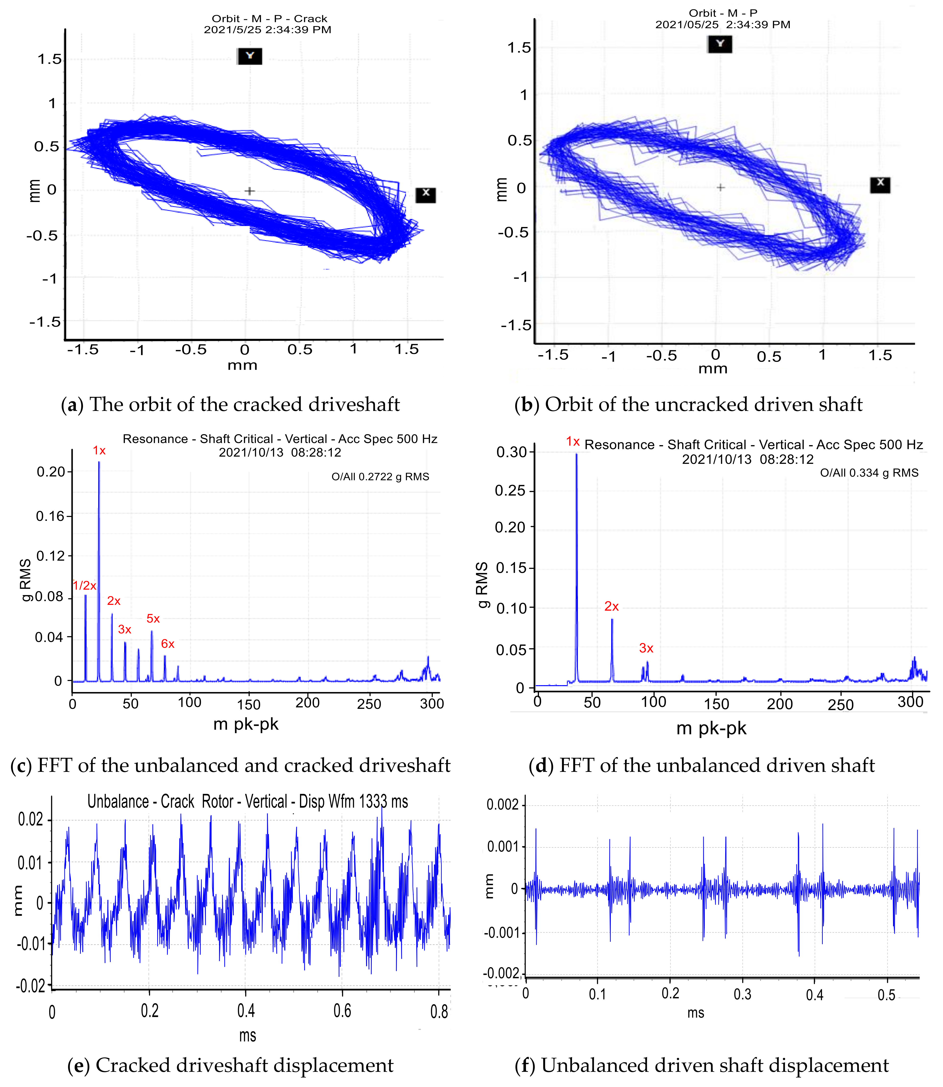
3.2. Crack Feature Extraction and Fault Identification

Vibration analysis of a rotor system in a viscous fluid is a condition-based maintenance technique that detects mechanical malfunctions through frequency ranges to monitor system degradation and provide a diagnosis by interpreting the vibration signal. Two extra masses of 250 g each attached to the discs are located at ∠0°. As shown in Figure 2b, the eccentric mass is added at 10 mm from the axis of rotation of the disc. For fluid instability, at a relatively significant speed, the eccentric mass of the transmission shaft has been moved entirely to the shaft’s midspan. Under certain conditions, the vibrations will suddenly increase to this position and spread throughout the system in a short time, which will result in strong vibrations. To avoid creating a turbulent flow pattern, the unbalanced shaft and location of the crack were well positioned, as well as the speed at which it is flowing was controlled by manipulating the controller (Figure 2b).
It is seen from Figure 5 that the presence of a breathing crack induces an orbit containing an important loop inside, which indicates a significant change in the phase and amplitude of the vibration. The experimental vibration signals in the air are of high vibration, characterized by the disappearance of the waveforms in the orbital patterns in the presence of super-harmonics. The orbit patterns of both shafts are roughly apposite in shape with a strong fluctuation of the driven shaft response. This observation is also illustrated in the lateral displacement response with a predominance of crack features. The test also connotes that the slight misalignment and breathing crack mechanism engendered the noise floor to rise, as seen with the generation of many harmonics. In Figure 5c,d, the lateral waveform responses of the coupled rotor system with a breathing crack and unbalance eased the extraction of the highly oscillated peak induced by the transverse cracks successfully.
Performing a frequency spectrum analysis shows that the crack introduced additional frequency components into the system response that were not present in the vibration spectrum of the uncracked driveshaft. An increase in vibration amplitude is observed on the cracked driveshaft with the presence of 1× to 7× amplitudes at a maximum amplitude of 0.02 mm. The frequency spectra in Figure 5c,d show that the first frequency of vibration of the system is influenced mainly by the stiffness properties. The peak 1× corresponds chiefly to the main frequency (balance effect), the 1/2× of the unbalanced impact, and the associated 2× subcritical resonance. More so, other harmonics are unbalanced, and the interaction of the crack and Hooke’s joint disturbance. It is essential to highlight that the transmission motion through the Hooke’s joint produced at 25% of the crack features is given by a few super-harmonics (2× and 3×). However, Figure 6 shows the impact of dynamic fluid forces and vibrations on the first harmonic of the primary and secondary shafts is similar in trend but different in amplitude. Since the hydrodynamics forces are considered, the harmonics of the shaft vibration waveforms and the shaft orbit vibrations of the driveshaft are entirely reduced in amplitude compared to the secondary shaft. The hydrodynamic forces are susceptible to the breathing of the transverse crack, and the variation of dynamic pressure around the crack shaft is minimal (Figure 6). Throughout the frequency spectrum, the higher harmonic amplitudes of the immersed driveshaft are lower, and no significant characteristics of a crack presence could be diagnosed in Figure 6c. The slight rise in sub-1/2× and super-harmonic 2×, 3× vibrations with the assumed solution of higher harmonics in the immersed shaft are not well visible, as shown in Figure 6b. Therefore, it is challenging to extract the features of the crack when the shaft is partially immersed in the fluid. Figure 5d,f shows that the measurement of the dynamic vibration of the secondary shaft is susceptible to the transient crack effect. The figures show clearly the 2×, 3×, and 4× vibration harmonics which are the best indicators for the crack on the driveshaft. The dynamic response, which considers the rotor deflection and orbit of the shaft center, is an ideal parameter of the rotor system and a useful parameter in diagnostics and monitoring shaft cracks in a viscous fluid. However, the mixed faults (unbalanced and cracked) are not easily detected on the immersed shaft because the severity of vibration of the uncracked secondary shaft is estimated from the motion transmission through Hooke’s joint.
Previous studies [6,7,8,9] have proven that the presence of sub-harmonics in the driveshaft’s running speed is considered the best indicator for diagnosing a crack. Thus, Figure 6c illustrates that this approach is erroneous for a given coupling system operating in a viscous fluid. The viscous fluid impacts the cracked driveshaft excitation by gradually reducing its amplitude. The vibration amplitude decreases if the fluid viscosity increases; i.e., more fluid density means less vibration. The signal processing results show that the proposed method can effectively detect the mechanical crack fault in a viscous fluid system using different control strategies. However, the crack feature extraction based on FFT is ideal under variable speed, but some difficulties appear when applied in viscous fluid with speed variation. This connotes that the harmonic frequencies of the nonstationary rotor system are not constant; therefore, the FFT application to the time-varying rotor system is avoided. In this condition, no sub-harmonics peaks are visible, which makes the analysis more complex and an appropriate technique. Hence, for reducing unwanted noise and vibrations, a vector quantity such as the energy dissipation per revolution of the rotor system based on the time-frequency method would be a more appropriate measure for the mixed fault vibration in a viscous fluid.
Observation 2: The influence of a viscous fluid near a cracked driveshaft and driven shaft can have several negative effects on the system. (1) Increased wear and tear: The turbulent fluid flow caused by the crack can lead to increased friction and wear on the surfaces of the driveshaft and driven shaft, which can accelerate the rate at which these components degrade. (2) Decreased efficiency: The fluid flow can also cause a loss of energy as it moves through the crack, which can decrease the overall efficiency of the system. (3) Reduced load-carrying capacity: The crack in the driveshaft or driven shaft can weaken the structural integrity of the component, which can reduce its load-carrying capacity. (4) Vibration and noise: The turbulent fluid flow can also create vibrations and noise in the system, which can be disruptive and potentially damaging to other components. It is therefore important to monitor the system to avoid serious damage.

4. Application of the Wavelet Synchrosqueezing for Fault Detection

Standard spectrum plots are insufficient to accurately describe transient responses in the extraction of viscous fluid characteristics in terms of rotor system noise and time-frequency variation; this shortcoming led to the implementation of the wavelet transform. Wang [17,18] et al. presented the nonlinear squeezing time-frequency transform (NSTFT), a revolutionary time-frequency analysis (TFA) technique that successfully overcomes the limitations of traditional TFA techniques in the detection of weak signals. As a result, the NSTFT technique proved successful in characterizing the IF’s oscillation feature since the TFA representation it produces only pertains to the signal phase and is unrelated to the signal amplitude. Experiments will assess crack detection efficiency using instantaneous frequency and nonlinear wavelet synchrosqueezing transform (NWSST). A mathematical description of the wavelet synchrosqueezing analysis is provided.

Mathematical Theory of the Wavelet Synchrosqueezing for Crack Detection

Wavelet synchrosqueezing is a mathematical process that denoises a rotor system signal by varying factors such as wavelet choice, thresholding method, and threshold values. The mathematical expressions below provide a conceptual understanding of wavelet synchrosqueezing. Let g(t) be the original signal function in the time domain.
  • First, the continuous wavelet transform (CWT) of a function g(t) with respect to a chosen parent wavelet function ψ(t) is calculated as:
    W g ( a , b ) = + g ( t ) ψ ( ( t b ) / a ) d t
    where a is the scale parameter and b is the translation parameter. Morlet’s mother wavelet was chosen for the present study because of its concentrated use of time and frequency space. To reduce or eliminate coefficients with small magnitudes or noise-like properties. Denoised coefficients Wg(a, b) are produced by transforming the thresholded coefficients Wsgtresh(a, τ) using the inverse synchrosqueezing transform.
    W g ( a , b ) = + W s g t r e s h ( a , τ ) ψ ( ( t τ ) / a ) d a d τ
    where the time-frequency plane is represented by τ . In order to rebuild the denoised version gs(t) of the original signal g(t), the denoised coefficients Wg(a, b) are combined with the inverse wavelet transform as follows:
    g s ( a , b ) = W g ( a , b ) ψ ( ( t b ) / a )
  • The wavelet transform coefficients are then used to estimate the instantaneous frequency (IF) of gs(t) at each time point t as follows:
    I F ( t ) = d α ( t ) / d t
    where d/dt stands for the derivative with respect to time and d α ( t ) is the wavelet transform phase Wgs(a, b).
  • Normalizing the mother wavelet causes the wavelet function to have unit energy at each scale. The energy of the wavelet coefficients is therefore redistributed to the corresponding instantaneous frequencies using the nonlinear wavelet synchronization transformation. The modified wavelet transform coefficients can be represented as follows:
    W g s ( a , τ ) = + W g ( a , b ) / a K ( ( τ α ( b ) ) / a ) d b
    where K(.) is a windowing function. The inverse continuous wavelet transform (ICWT) is then applied to the modified coefficients Wgs(a, τ) to finally obtain the final version of the improved nonlinear squeezing time-frequency transform (NSTFT) representation of the original signal g(t), with improved localization of its content energy.
    g s ( t ) = + W g s ( a , τ ) ψ ( t τ / a ) d a d τ
In the next section, experiments at 1081 RPM investigate crack detection using wavelet synchrosqueezing transform. Results show normalized wavelet synchronized power spectrum for rotor transient responses with and without crack, confirming previous analytical observations in [13].

5. Crack Characteristics and Fault Identification Based on Synchrosqueezing

The biggest challenge in this experimental work is to process a large amount of data using wavelet synchrosqueezing, which can be useful to help analyze the defects of the twin-rotor system. The generation of sequencing data experimentally from a defective rotor system allows the analysis to be effective using Matlab, very useful in the processing of mechanical data, and the results are presented and discussed below.
The results of the synthetic signal obtained by the IFs, NWSSTs, and NSTFTs are shown in Figure 7 and Figure 8 where each method can separate the frequency components well and generate higher time-frequency resolution than the FFT methods. The technique is mainly based on wavelet ridge and energy spectrum concepts. The maximum energy ridge is extracted in rotations per sample of the wavelet synchrosqueezed transform for fault identification as represented in Figure 7 and Figure 8. After a while, slight variations of frequency are observed. Thus, an oscillation around the fundamental value of 4.8 Hz can be noted. The synchrosqueezing power spectrum consists of both unbalanced and crack effects for reducing unwanted noise and vibrations. By jointly representing the instantaneous amplitude of the IF as a function of time, the IF contains the signal denoted that the scalogram made it possible to visualize the signature of the failure caused by the unbalanced and cracked driveshaft. It is noticed from the IF that the amplitude of variations of the uncracked driven shaft increases considerably, and the peak amplitudes of the driveshaft are less disturbed when a transverse crack with fluctuated Hooke’s joint is used. Several unsynchronized harmonics of the cracked driveshaft speed can be seen (indicated by the color), i.e., periodic vibrations with frequencies at no integer multiples of the driveshaft speed (Figure 7c,d). This means that the Hooke’s joint with more considerable vibration will ramp up the amplitude of variation of the secondary shaft with an increase in the motor speed. To concentrate solely on the frequency of mechanical vibration for a more straightforward diagnosis of the source of the vibration, the analysis of the NSTFT showed that the energetic content is distributed over a larger frequency bandwidth. If the evolution through time of the peak is at 330 Hz for both shafts, it implies an oscillation diminution around a defined frequency (Figure 7e,f). Consequently, the graphs denote the instantaneous and uneven variation of the amplitudes of the main frequency with respect to time. The sudden jump around the main frequency, as shown in Figure 7e,f), implies that the impact of the mixed unbalance and crack on the system ascertains the catastrophic results, which correspond to a chaotic operating system (Figure 7e). The characteristic frequency of crack-related defects increases over time between the two frequencies (320 to 500 Hz). After some time, considerable frequency variations and the secondary shaft signal were observed around the fundamental value of 330 Hz (Figure 7f).
The fluid attached to the cracked driveshaft may cause self-excited vibrations and significant disturbance. Hence, the peak of the periodic harmonic as a result of the viscous fluid reaction to the breathing mechanism confirms Hooke’s joint mixed-mode influence on the driveshaft response.
The fluid flow around the cracked driveshaft influences the dynamic vibration of the rotor’s shaft. It is demonstrated that the significant changes on the 3D NWSST of the driveshaft with an abrupt drop of the predominant harmonics are due to the fluid forces (Figure 8c), unlike the 3D-driven continuous shaft response. The NSTFT shows a fluctuation of the harmonic peaks and completes the oscillation for a short duration at the vicinity of the critical speed. IF and variation of energy concentration are successfully used and appear to be the ideal tool for detecting a crack signal of a transient or nonstationary nature at the first critical speed. Figure 8e,f shows the dissipation of the effect of the crack in the presence of fluid, which is significant in the main crack frequency amplitude is very high [400–450 Hz], unlike the secondary shaft [150–200 Hz]. The driven shaft 2 in Figure 8f indicates that the amplitude becomes substantial when the fluid force is negligible. Therefore, it implies that the feature extraction of the connected shafts with unbalance and cracks hidden in the viscous fluid could be reliably monitored using the SWT. The SWT provided better energy-concentrated TF representation and detected crack components from multi-component non-stationary signals in a fluid medium.
Observation 3: The computations yielded desirable results and proved the authenticity of the Matlab algorithm developed to extract the features of cracks in fluid rotor systems. It is observed that as the crack and Hooke’s joint coexist, the resonance frequency gradually increases. As the viscous fluid interacts with the cracked driveshaft, the amplitude of vibration of the driveshaft decreases with multiple fluctuations and distortion of the harmonic’s peaks. Due to the amortizing parameters, the corresponding driven shaft amplitude of vibration under the same condition increases considerably with some features similar to the crack characteristics. The performed experimental analysis shows that the magnitude of the spectral components depends on the fluid property and Hooke’s joint disturbance. From these results, the synchrosqueezing vibration measurement is an apt signal-processing tool for extracting the crack feature and detecting Hooke’s joint fluctuations in operating machinery. It is also suitable to evaluate the severity of the combined crack and cardan joint fluctuation.

6. Conclusions

Dynamic analysis of cardan shafts in underwater environments is crucial for offshore structures, marine propulsion systems, and underwater vehicles. Understanding fluid dynamics, resonant frequencies, damping effects, and load distribution helps to optimize the design and ensure reliable operation. A detailed experimental setup and vibration analysis of a twin-rotor connected through a flexible Hooke’s joint with or without defects has been conducted in a viscous fluid medium. The vibrations generated by the modified Rotor-Kit 4 in a fluid medium originated from the parametric excitation engendered variations in the transient stiffness, Hooke’s joint perturbation, the hydrodynamic resistance forces, and the self-aligned bearing. Other factors on which the vibration system depends include the motor speed of the system and the perturbation motion transmitted by Hooke’s joint. The classical vibration techniques (FFT, orbit maps, and waveforms) used in the first experimental analysis to diagnose the system disturbance have been conducted and yielded many harmonics of integers multiple of the rotational speed and disturbance to characterize the behavior of the coupled system. The drawback of this conventional technique in a fluid medium, which was resolved and justified in this study, is the use of the synchrosqueezing wavelet transform. This technique involves using wavelet transform to decompose a signal into its frequency components, and then using a synchrosqueezing algorithm to enhance the frequency information and reduce the noise in the signal. The experimental analysis results indicate that the time-varying stiffness induced by a transverse crack in a viscous fluid is the original cause of the frequency-modulated feature of the dynamic response of a cracked cardan system. It is thus established that the variation in stiffness due to the motion of the submerged cracked driveshaft and the coupling joint could be small, as reported in earlier published theoretical work [14,15].
The effectiveness of the NWSST and NSTFT methods in accurately locating and identifying pulse peaks was validated by comparing extracted standard features in the time and frequency domain with the results of the time-frequency representation. Finally, the structural integrity of the shafts and the severity of the cracked driveshaft damage can be determined in a fluid medium by analyzing the more energy-focused time-frequency results, which denote better time-frequency localization and a better characterization of the variation over time. However, accurately measuring the turbulent velocity of the fluid acting on the driveshaft, whose viscosity and temperature can vary instantaneously, could pose another significant challenge to fault diagnosis, when interpreting the results of a cracked driveshaft surrounded by viscous fluid.

Author Contributions

The topic of this research was conceptualized by B.X.T.K. and A.A.A.; formal analysis was performed by B.X.T.K.; the first version manuscript was prepared by B.X.T.K.; this version of the manuscript was read and approved by B.X.T.K. and A.A.A., who also substantially contributed to it. All authors have read and agreed to the published version of the manuscript.

Funding

This work is based on the research supported in part by the Vaal University of Technology (VUT), South Africa, through the Department of Higher Education and Training University Capacity Development Grant.

Data Availability Statement

The data used to support the findings of this study are available from the corresponding author upon request.

Conflicts of Interest

The authors declare no conflict of interest.

References

  1. Yang, Y.; Zhang, Y.; Tan, X. Review on vibration-based structural health monitoring techniques and technical codes. Symmetry 2021, 13, 1998. [Google Scholar] [CrossRef]
  2. Alugongo, A.A. A nonlinear torsional vibration model of a propeller shaft with a crack-induced parametric excitation and a Hooke’s joint type of kinematic constraint. In IEEE Africon’11; IEEE: Piscataway, NJ, USA, 2011; pp. 1–7. [Google Scholar]
  3. Asonja, A.; Desnica, E. Reliability of agriculture universal joint shafts based on temperature measuring in universal joint bearing assemblies. Span. J. Agric. Res. 2015, 13, e0201. [Google Scholar] [CrossRef] [Green Version]
  4. Desnica, E.; Ašonja, A.; Kljajin, M.; Glavaš, H.; Pastukhov, A. Analysis of Bearing Assemblies Refit in Agricultural PTO Shafts. Teh. Vjesn. 2023, 30, 872–881. [Google Scholar]
  5. Wahab, A.M.; Rasid, Z.A.; Mohd Rudin, N.F.; Abu, A. Dynamic stability of shaft interconnected through joint. ARPN J. Eng. Appl. Sci. 2015, 10, 6310–6318. [Google Scholar]
  6. Al-Hussain, K.M.; Redmond, I. Dynamic response of two rotors connected by rigid mechanical coupling with parallel misalignment. J. Sound Vib. 2002, 249, 483–498. [Google Scholar] [CrossRef]
  7. Dupal, J.; Zajíček, M. Analytical periodic solution and stability assessment of 1 DOF parametric systems with time varying stiffness. Appl. Math. Comput. 2014, 243, 138–151. [Google Scholar] [CrossRef]
  8. Yi, C.; Lin, J.; Ruan, T.; Li, Y. Real time Cardan shaft state estimation of high-speed train based on ensemble empirical mode decomposition. Shock. Vib. 2015, 2015, 912483. [Google Scholar] [CrossRef] [Green Version]
  9. Patel, T.H.; Darpe, A.K. Experimental investigations on vibration response of misaligned rotors. Mech. Syst. Signal Process. 2009, 23, 2236–2252. [Google Scholar] [CrossRef]
  10. Ludwicki, M.; Awrejcewicz, J.; Kudra, G. Spatial double physical pendulum with axial excitation: Computer simulation and experimental set-up. Int. J. Dyn. Control 2015, 3, 1–8. [Google Scholar] [CrossRef] [Green Version]
  11. Zhang, G.; Du, J.; To, S. Study of the workspace of a class of universal joints. Mech. Mach. Theory 2014, 73, 244–258. [Google Scholar] [CrossRef]
  12. Golafshan, R.; Dascaliuc, C.; Jacobs, G.; Roth, D.; Berroth, J.; Neumann, S. Damage diagnosis of Cardan shafts in mobile mining machines using vibration analysis. In Proceedings of the IOP Conference Series: Materials Science and Engineering, Sanya, Chian, 12–14 November 2021; IOP Publishing: Bristol, UK, 2021; Volume 1097, p. 012019. [Google Scholar]
  13. Tchomeni, B.X.; Sozinando, D.F.; Alugongo, A. Influences of hydrodynamic forces on the identification of the rotor-stator-rubbing fault in a rotating machinery. Int. J. Rotating Mach. 2020, 2020, 8816191. [Google Scholar] [CrossRef]
  14. Tchomeni, B.X.; Alugongo, A. Modelling and Dynamic Analysis of an Unbalanced and Cracked Cardan Shaft for Vehicle Propeller Shaft Systems. Appl. Sci. 2021, 11, 8132. [Google Scholar] [CrossRef]
  15. Tchomeni Kouejou, B.X.; Alugongo, A.A. Dynamic Analysis of a Rotating Cardan Shaft under the Influence of a Breathing Crack and Dense Fluid Force. Shock. Vib. 2022, 2022, 5021488. [Google Scholar] [CrossRef]
  16. Sabnavis, G.; Kirk, R.G.; Kasarda, M.; Quinn, D. Cracked shaft detection and diagnostics: A literature review. Shock. Vib. Dig. 2004, 36, 287–296. [Google Scholar] [CrossRef]
  17. Wang, S.; Chen, X.; Wang, Y.; Cai, G.; Ding, B.; Zhang, X. Nonlinear squeezing time–frequency transform for weak signal detection. Signal Process. 2015, 113, 195–210. [Google Scholar] [CrossRef]
  18. Jiang, Q.; Suter, B.W. Instantaneous frequency estimation based on synchrosqueezing wavelet transform. Signal Process. 2017, 138, 167–181. [Google Scholar] [CrossRef]
Figure 1. Experimental setup with (a) a schematic test rig rotor system (b) coupled twin shaft (c) Modified Rotor-Kit 4 components (1) and (2)—Shaft-disc 1.2, (3)—Rectangular Plexiglas tank, (4)—Oil 32, (5)—Crack Simulator, (6)—AC Motor.
Fluids 08 00211 g001
Figure 2. Pictures of the test (a) 12 mm SealMaster MSF-27 Flange Bearing, (b) Data acquisition system, (1)—Computer Screen, (2)—Scout Ascent, (3)—Controller, (4)—Tachometer (5)—Probe sensors. (c) Crack unbalance set-up (d)—Crack simulator system (6).
Fluids 08 00211 g002
Figure 3. Baseline response of the balanced rotors system passing through the first critical speed.
Fluids 08 00211 g003
Figure 4. Baseline response of the balanced twin-rotor system in a viscous GST 32 oil.
Fluids 08 00211 g004aFluids 08 00211 g004b
Figure 5. Experimental response for the unbalanced and crack fault conditions near the critical speed.
Fluids 08 00211 g005
Figure 6. Dynamic vibration of the unbalanced and uncracked output shaft at 500 rpm in a viscous GST 32 Oil.
Fluids 08 00211 g006aFluids 08 00211 g006b
Figure 7. Time-Frequency ridges evolution of unbalanced shafts with a crack at 1081 rpm.
Fluids 08 00211 g007
Figure 8. Time-Frequency ridges evolution of unbalanced shafts with a crack at 500 rpm in a GST 32 Oil.
Fluids 08 00211 g008
Table 1. Rotor system Rotor-Kit 4 parameters.
Shaft ParametersValue and UnitsBearing StiffnessValue and Units
Length of the shaft (L)570 mmLeft bearing stiffness7.35 × 105 Nm−1
Shaft Diameter (D)10 mmRight bearing stiffness7.35 × 105 Nm−1
Outer Diameter (Dout)75 mmDamper200 Ns/m
Inner Diameter (Din)10 mmDiscsValue and Units
Density of the material
( φ )
7800 kg m−3Mass (M)16.845 kg
Modulus of elasticity (E)2.11 × 10¹¹ PaEccentricity mass (mu)0.25 kg
Viscous damping ratio0.8 × 10−6 s−1Mass eccentricity (e)10 mm
Hooke’s joint angle ( β )Disc thickness (Ddisc)25 m
Table 2. Parameters of the experimental study.
Characteristics of the Oil
Oil type GST Oil 32 (CHEVRON)GST Oil 32 (CHEVRON)
ColourColourless to yellow
Physical StateLiquid
Vapour Pressure (at 22 °C)<0.01 mmHg@ 22 °C
Viscosity of the oil (at 22 °C)145 mPa·s
Density of the oil866 kg/m3
Depth of oil bath4 mm
Frequency of oscillations0.666 à 30 Hz
Amplitudes of oscillations0.36 et 0.4 mm
Initial thicknesses of oil film0.4 à 0.8
Disclaimer/Publisher’s Note: The statements, opinions and data contained in all publications are solely those of the individual author(s) and contributor(s) and not of MDPI and/or the editor(s). MDPI and/or the editor(s) disclaim responsibility for any injury to people or property resulting from any ideas, methods, instructions or products referred to in the content.

