Article

Dual Numerical Solution for 3D Supersonic Laminar Flow Past a Blunt-Fin Junction: Change in Temperature Ratio as a Method of Flow Control

Institute of Physics and Mechanics, Peter the Great St. Petersburg Polytechnic University, St. Petersburg 195251, Russia
*
Author to whom correspondence should be addressed.
Fluids 2023, 8(5), 149; https://doi.org/10.3390/fluids8050149
Submission received: 29 March 2023 / Revised: 28 April 2023 / Accepted: 5 May 2023 / Published: 11 May 2023
(This article belongs to the Special Issue High Speed Flows, 2nd Edition)

Abstract

:
The results of a numerical solution of the problem of supersonic flow past a blunt fin mounted on a plate with a developing boundary layer are presented. The initial formulation of the problem is based on the presented in the literature computational and experimental investigation, in which the laminar flow regime was studied for the fin perpendicular to the plate at the free-stream Mach number equal to 6.7. Earlier, the authors showed (2020) that under these conditions there exist two stable solutions to the problem. These solutions correspond to the metastable states of flow with different configurations of the vortex structure and different patterns of local heat transfer. In the present study, the influence of a temperature ratio on the vortex structure in the separation region, local heat transfer, and the possibility of obtaining a dual solution are investigated. The ability to switch between solutions of two types using a short-time change in the plate temperature ratio are shown.

1. Introduction

One of the main requirements for the design of high-speed vehicles is the ability to withstand the aerodynamic heating that occurs at these speeds [1]. The areas that are most susceptible to such thermal loads are the stagnation zones that form due to flow separation. In the case of supersonic flow past any obstacle mounted on the streamline surface, separation of the flow occurs due to the interaction of the shock wave with the boundary layer. The complex problem of the shock wave/boundary layer interaction is of great scientific and practical importance and has been intensively studied for many years, starting from the 1950s (see, for instance, [2,3,4,5,6,7,8,9,10,11,12,13,14,15,16,17]).
Certainly, the features of the three-dimensional shock wave/boundary layer interaction are very complex, and it especially concerns the nature of heating and the peak value of the heat flux in the interaction region. Therefore, it remains necessary to conduct studies to determine the exact nature of the three-dimensional flow above the surface under given geometric or flow conditions; at the same time, a numerical study makes it possible to study a wide range of determining parameters.
The model problem of supersonic flow past a symmetric blunt fin mounted on a plate is most often considered in the literature [5,6,7,8,9,10,11,12,13,14,15]. This type of geometry is a simplified representation of a wing–body or fin–body junction on a high-speed vehicle [16]. Generally, the flow is essentially three-dimensional, with a complex shock wave structure. The bow shock that occurs in front of the body interacts with the boundary layer and the separation region arising upstream of the fin. The pressure rise across the shock is transmitted upstream through the subsonic part of the boundary layer that leads to flow separation. The separated flow rolls up into a series of horseshoe vortices as it goes around the fin. Within the separated flow region, there is a mixture of subsonic and supersonic flow. The complex nature of the flow in the separation region gives rise to a number of secondary shocks, and hence to multiple shock–shock interactions and triple point formations. Areas of enhanced heating and pressure are experienced on the plate surface and the fin itself, and at the same time, peak values are much higher than the undisturbed values.
In the literature, studies are carried out both for the turbulent and laminar cases, and the last one is especially important for the practical application of high-speed flows, since high-Mach-number flows are more resistant to laminar–turbulent transition [17,18].
The first studies on numerical simulation used computational meshes that could not provide sufficient resolution of all flow features [5]. To date, high-quality numerical simulations for this configuration have been carried out in many works, and the results obtained are in a good agreement with the experimental data [7,8,9,10,13,14]. Despite the progress reached in the investigations of such type of flows, at present there are some aspects that require more detailed study. In particular, the question of a possible non-uniqueness of the solution remains a weakly investigated area.
Among other papers, one should note the extended experimental and numerical study by Tutty et al. [8], where the laminar air flow with the free-stream Mach number of 6.7 past a blunt fin is considered. The flow structure in front of the streamlined body and the plate–surface heat transfer were investigated for three values of the Reynolds number based on the leading edge fin diameter: ReD = 1.25 × 10⁴, 2.50 × 10⁴, and 3.75 × 10⁴. A good agreement between the calculation results and the experimental data was demonstrated. In the later computational study [9], it was established that the numerical solution is time dependent in certain cases investigated in [8]. Recently, in our investigations [14] it was shown that, under the conditions of study [8], a dual solution exists with two different solutions corresponding to metastable states of flow with different configurations of the vortex structure in the leading separation region; the revealed duality of the solution persists in a certain Reynolds number range [15]. At the same time, concerning the computations, the authors of [8] interpreted the obtained numerical solutions as stationary and unique for all the cases considered (ReD = 1.25 × 10⁴, 2.50 × 10⁴, and 3.75 × 10⁴). It should also be noted that the possibility of existence of a non-unique solution in supersonic flow past a body, system of bodies, or their separate parts is well-known fact; the physical aspect of this problem consists in the strong nonlinearity of gas–dynamic processes. One of the examples is the experimental and numerical confirmation of the duality of the pattern of the supersonic flow past the model of an axisymmetric body with the rectangular ring cavity [19,20].
In our previous study, it was established that the dual solution occurs in some range of determining parameters, such as the Reynolds number and the Mach number, and also in different geometric configurations [15]. In the present work, we continue our investigations of the possibility of dual solution existence in the case when the temperature ratio is varied. On the other hand, one of the important problems, both from a fundamental and practical point of view, is the possibility of switching between the solutions of two types. In practical applications, heating (or cooling) some areas of the flow using various methods is often used in flow control [21,22,23,24].
Accordingly, the main objective of the present study is to investigate numerically the temperature ratio effect on the possibility of obtaining a dual solution in supersonic flow past a blunt fin mounted on the plate. In addition, we present our initial experience in switching between solutions of two types by means of introducing a short-time change in the plate temperature.

2. Problem Definition and Computational Aspects

The formulation of the problem is based on the data of the above-mentioned computational and experimental study [8], in which the structure of laminar supersonic air flow (Mach number M = 6.7, Prandtl number Pr = 0.71, and ratio of specific heats γ = 1.4) past the fin mounted on the plate was studied (Figure 1). Following [8], we assumed that the flow is laminar in the entire domain. The Reynolds number calculated from the bluntness diameter (D = 2.5 mm) corresponds to the minimum value considered in [8] (ReD = 1.25 × 10⁴). The free-stream total temperature is equal to T0 = 630 K.
The computational domain is illustrated in Figure 1. The fin is located at a distance of Lplate = 145 mm from the plate leading edge, and the remaining dimensions of the computational domain were taken in accordance with [8], as follows: R = 76.5 mm, Lf = 60 mm, and H = 25 mm.
The full three-dimensional Navier–Stokes equations for a thermally and calorically perfect gas were solved numerically. The temperature dependence of the viscosity coefficient was evaluated with Sutherland’s law. Homogeneous flow was specified on the inlet boundary of the computational domain and the no-slip condition was implied on the body surface and on the plate. The non-reflecting boundary conditions were specified on the lateral and upper boundaries and the zero-gradient condition is specified at the outlet.
In [8], the body surface and the plate were maintained at a constant temperature, Tw = 300 K, which corresponds to a temperature ratio of Tw/T = 4.76. In the present study, the plate-surface temperature was varied from 250 K to 500 K (temperature ratio ranges from 3.97 to 7.94), whereas the body temperature was fixed at 300 K.
The finite-volume unstructured code SINF/Flag-S [12,13] was used to perform calculations. The convective fluxes on the faces of control volumes were evaluated using the second-order AUSM scheme [25] applying the van Albada TVD limiter [26]. For the evaluation of viscous fluxes, a nominally second-order scheme was used. The numerical scheme is described in detail in [12].
All simulations were carried out based on the time-dependent formulation, an implicit time-advancing scheme of second-order accuracy (the backward three-layer scheme) was used, and the used dimensionless time step is equal to ΔtU/Lplate = 3.67 × 10⁻⁴t = 5 × 10⁻⁸ s). Note that in all considered cases with different (fixed) values of the temperature ratio the transient process converged to a steady-state solution.
The simulations were performed using a quasi-structured grid consisting of 20 million cells. The parameters of the computational grid were chosen based on a previous grid-convergence study [14]. The used grid has about 70 cells across the incoming boundary layer, which has a thickness of about 1.2D before separation; the first near-wall cell is about 0.01 mm in the normal direction. Fragments of the grid near the fin leading edge are illustrated in Figure 2. In the framework of the present study, calculations for some cases were performed also using a locally refined grid (of 50 mln cells). The results of the work were obtained using computational resources of Peter the Great Saint-Petersburg Polytechnic University Supercomputing Center (www.spbstu.ru).

3. Results

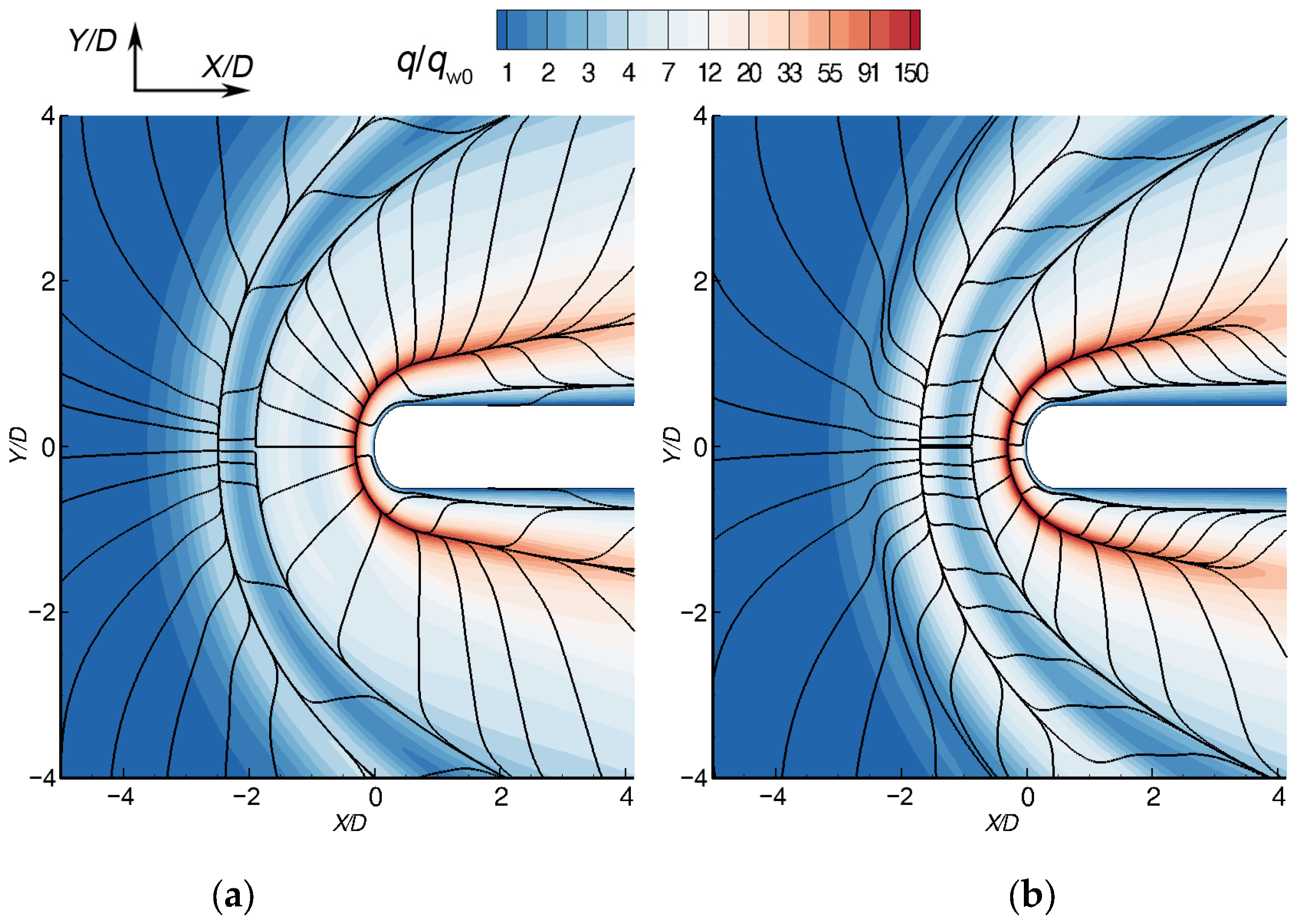
3.1. Duality of the Flow Pattern

Previously (see Section 1), it has been revealed that in the base case (corresponding to the parameters given in [8]: ReD = 1.25 × 10⁴ and Tw/T = 4.76) there is a dual solution. As described in detail in [14], in this case one solution (termed Solution II below) can be obtained using uniform initial fields, which are constructed from the flow parameters at the computational domain inlet. Another solution (denoted further as Solution I) is managed to be obtained using “auxiliary” initial fields extracted (at an arbitrary instant) from a nonstationary solution, which develops in computations at a considerably higher Reynolds number (in particular, at ReD = 2.5 × 10⁴).
A general view of the flow structure, which corresponds to Solution I, is shown in Figure 3. This figure illustrates the volume streamlines, as well as the relative heat flux distribution over the body and plate surface (qw0 is the heat flux calculated in the case of a plate without obstacle). The main features of the flow are characterized by the formation of the separation region with a system of horseshoe vortices that expand around the side of the fin, and by a strong non-monotonicity of the heat flux distribution in the junction region.
To demonstrate the distinctive features of the two stable solutions, Figure 4 and Figure 5 present, respectively, the flow structure in the plane of symmetry and the plate-surface relative heat flux distribution with superimposed streamlines. The solutions differ mainly in the length of the leading separation region (LS/D) and in the location of the center of the main horseshoe vortex (Xv/D). Distinctions in vortex structure also lead to different characteristics of heat flux distribution. A more extended analysis of the dual solution is given in [15].
Figure 6 shows the calculated distributions of the plate-surface nondimensional heat flux (normalized by the flat plate value qwp) along the symmetry line (a) and along a cross line, x/D = 1 (b). In addition, experimental and numerical data from [8] are presented. One should note the main distinctions in the heat flux distributions along the symmetry line computed for two solutions: in addition to the global maximum (outside the field of Figure 5), the heat flux distributions related to Solution II contain one more well-pronounced local maximum, whereas in Solution I two local maxima of a lower level are predicted. Similar trends persist as the flow turns around the body, except that the first local maximum in Solution I is faded out (Figure 6b). Solution I agrees well with experimental and computational data reported in [8] for this metastable flow state. One can also see that there is almost no difference between the results obtained using the base grid and the refined one for both solutions, which confirms the sufficiency of the grid resolution.

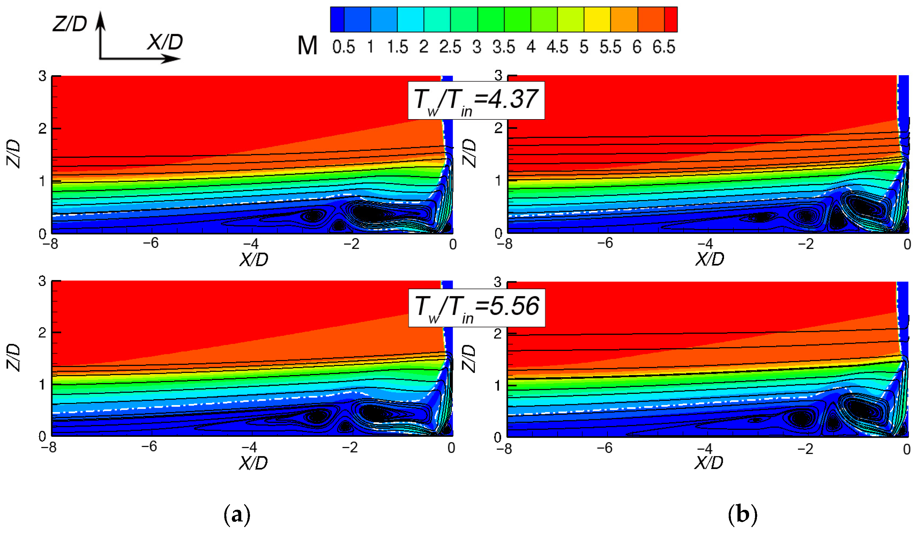
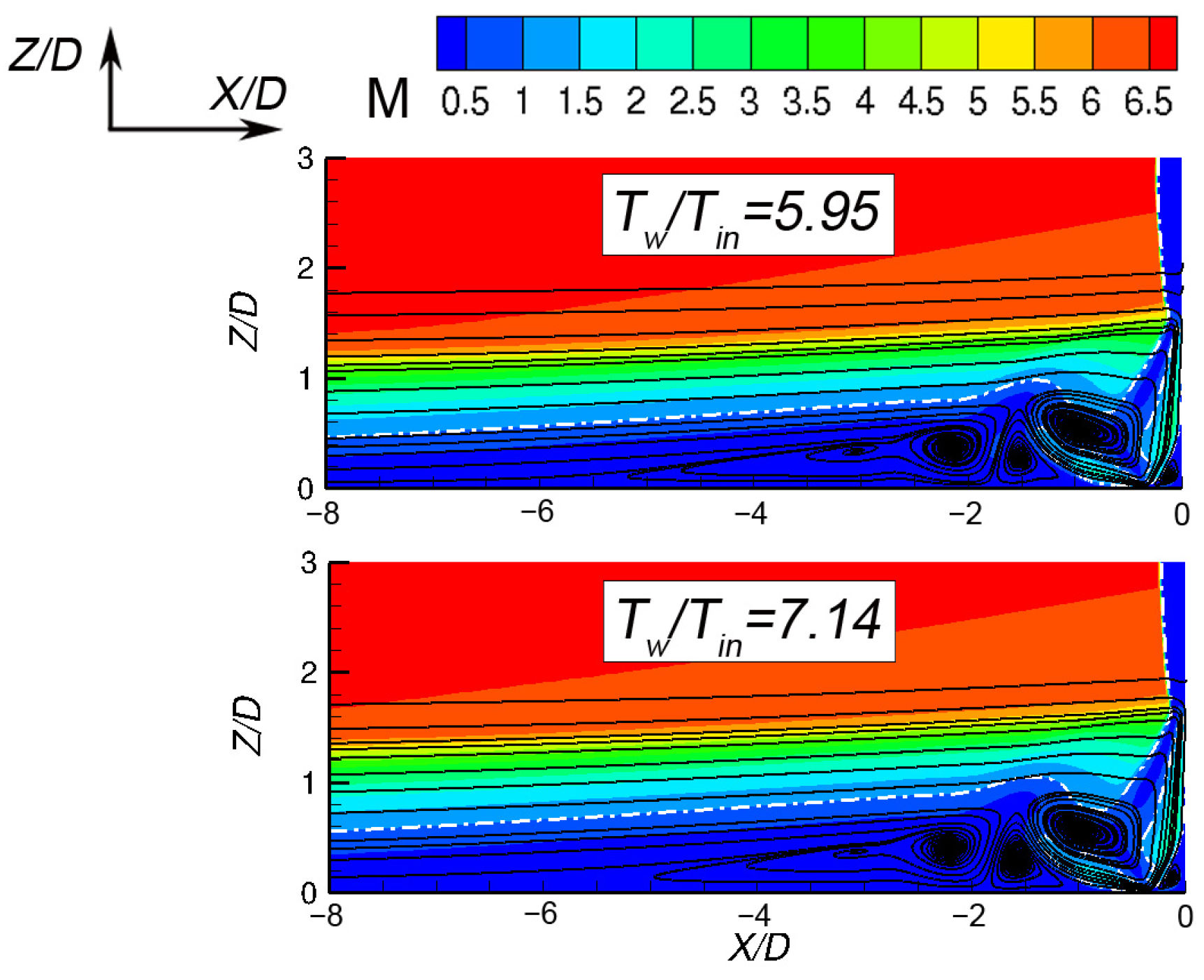
3.2. Influence of the Temperature Ratio

To study the influence of the temperature ratio on the flow pattern in the case of an existing dual solution, a series of parametric calculations was carried out at various values of the plate temperature, whereas the body temperature was fixed. The plate temperature was varied from 250 K to 500 K with a step of 25 K, which corresponded to a temperature ratio range of 3.97 to 7.94. To obtain a solution for each new value of the temperature ratio, the fields of gas dynamics quantities corresponding to either Solution I or Solution II obtained for the previous value of the plate temperature were set as initial fields. This procedure of gradual increasing (or decreasing) of the plate temperature was started from the fields obtained for the base case (Tw/T = 4.76). The parameters of all the cases considered, as well as some representative characteristics of the studied flow (discussed below), are given in Table 1. This table also provides data for the boundary layer thickness, δ, calculated in the case of the plate without an obstacle and evaluated at X/D = 0.
Concerning the choice of the lower limit of variable temperature Tw, one should note that in the case of the plate temperature of 225 K (and lower), Solution I does not reach a steady state. That was a reason for limiting the lowest temperature ratio by a value of 3.97. In principle, it is possible to find a more accurate “critical” temperature ratio, separating steady and unsteady solutions, but it was out of the purposes of the present study.
The results of the performed parametric calculations show that for values of the temperature ratio less than or equal to 5.56, there are two stable solutions, while starting from a value of 5.95 only a single solution exists. The presented data allow us to conclude that a critical value of the temperature ratio, at which the duality of the solution disappears, lies in the range from 5.56 to 5.95. Figure 7 shows bifurcation diagrams which illustrate changes in the location of the main horseshoe vortex center, |Xv|/D, and the separation region length, LS/D, depending on the temperature ratio (calculated values are given in Table 1). For the solution of the first type, an increase in the temperature ratio leads to a displacement of the center of the main horseshoe vortex towards the streamlined body, while the length of the upstream separation region remains practically unchanged. In the second solution, in contrast to Solution I, |Xv|/D varies slightly, but some reduction in the separation region length is observed with a decrease in the temperature ratio.
To illustrate the effect of temperature ratio on the dual solution vortex structures, Figure 8 shows the Mach number fields in the symmetry plane for two values of the temperature ratio: Tw/T = 4.37 and Tw/T = 5.56. The last value corresponds to the largest one at which two stable solutions are obtained. One can see that in both solutions the upstream separation region becomes thicker when the temperature ratio is increased. This effect (more pronounced in the case of Solution II) is an expected observation, since an increase in the temperature ratio, resulting in lower gas density in the near plate layers, leads to an increase in the incoming boundary layer thickness (see Table 1). From the other side, the main peculiarities of flow rearrangement inside the separation region due to the temperature ratio change are different for the two solutions. In the case of Solution I, an increase in the temperature ratio leads to a notable shift of the main vortex towards the streamlined body, despite the separation region length remaining nearly unchanged. Contrary to that, in the case of the second solution, a gradual increase in the temperature ratio leads to a noticeable increase in the separation region length, whereas the multi-vortex structure adjacent to the fin leading edge remains nearly the same.
One can see that the distinguished features of the dual solution maintain with changes in the temperature ratio, whereas the temperature ratio influence on the solution of the same type is relatively weak (at least in the range considered). Figure 9 shows Mach number fields in the symmetry plane for two values of the temperature ratio at which only a unique solution is obtained; as in case of a dual solution, the temperature ratio effect is insignificant. A comparison of Figure 8 and Figure 9 allows one to conclude that the vortex structure of the unique solution is closer to the one inherent to the solution of the second type.
The temperature ratio influence on the heat flux distribution is illustrated in Figure 10. One can see again that the temperature ratio effect is less pronounced than the distinctions between the solutions of two types. It is also remarkable that the heat flux distribution corresponding to the unique solution is closer to the one typical to Solution II.

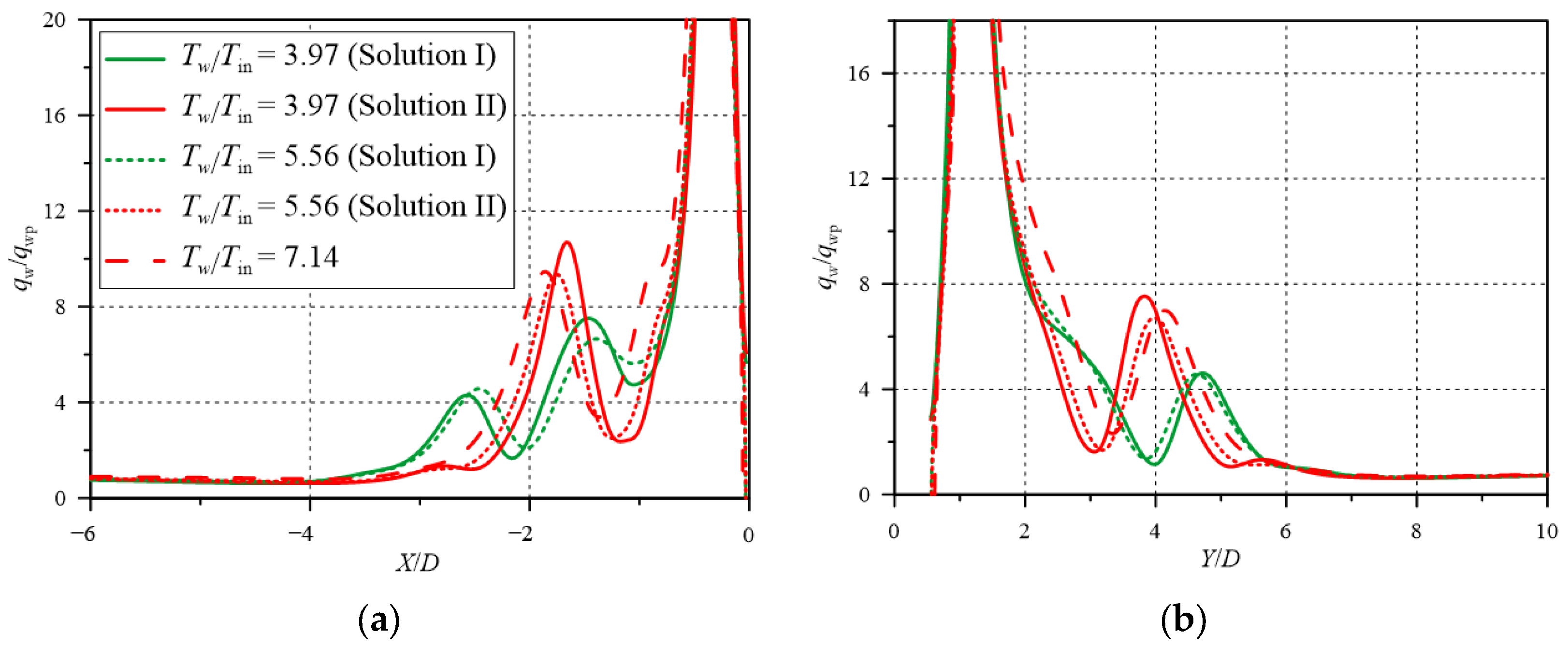
3.3. Switching the Flow Regime by Changing Plate Temperature

One of the important fundamental issues is the stability of the metastable solutions of both type under the external action of a finite amplitude. From the other side, the existence of a dual solution allows performing flow control by switching between these solutions using, in particular, a short-time impact. Here, we present our initial experience in switching between solutions of two types by means of a short-time change in the plate temperature. In the case presented below, for both solutions obtained at Tw/T = 4.76 (base case), the following procedure was applied: starting from the initial fields corresponding to the steady-state solutions of one or another type, the plate temperature was suddenly changed to some value (at time t1) and a transient process of flow rearrangement was calculated during a short time (2.5 × 10⁻⁴ s); then (at time t2), the plate temperature was returned to the original value. The time dependence of the plate temperature is shown in Figure 11 (top row); in the figure, the values of temperature in a monitoring point are also shown (bottom row) to illustrate the transient process of the flow rearrangement (the monitoring point is located inside the separation region at X/D = −1.6, Z/D = 0.6, and Y/D = 0). One should note that for switching from Solution I to Solution II (Figure 10a), the plate temperature should be increased. This can be explained by analyzing the bifurcation diagram (see Figure 7), where one can see that only the solution of the second type can exist at high temperature ratios. In addition, the lowest value of the plate temperature increase, at which switching could be achieved, should not be less than 100 K (for the chosen duration of the plate temperature change). To switch from Solution II to Solution I (see Figure 11b), one should reduce the plate temperature, and this decrease should be dramatic (by 250 K). In both cases considered, the transition process to a steady state after switching to the original plate temperature (at time t2) lasts about 3 × 10⁻⁴ s, which is comparable to the provoking action duration.
The fields of the Mach number at the symmetry plane, obtained at the moment t2, are shown in Figure 12. Compared with the fields shown in Figure 4 for solutions of each type, it can be clearly seen that the corresponding fields at the time moment t2 are close to the steady-state ones in the following way: Figure 12a is similar to Figure 4b and vice versa.
To illustrate the evolution of the vortex structure during the switching process, the time dependences of the location of the main horseshoe vortex center and the separation region length are shown in Figure 13. It is of interest to note the non-monotonicity of the switching process: when the switching from Solution I to Solution II occurs, the main horseshoe vortex noticeably shifts outwards from the fin and then shifts in the opposite direction; the separation region length first decreases, then increases strongly and then decreases again. In the case of switching from Solution II to Solution I one can see a similar behavior (except small differences in the horseshoe vortex shifting process).

4. Discussion

The present work was aimed at the numerical simulation of supersonic flow past a symmetric blunt fin mounted on a plate, along which the boundary layer develops, for the conditions based on the computational and experimental work [8]. It was established earlier that in such configuration a dual solution can exist in some range of determining parameters. In the present study, it was shown that a dual solution exists in some range of the temperature ratio. By means of gradually increasing the temperature ratio, it has been revealed that there is a critical value at which the duality of the solution disappears: its value lies in the range from 5.56 to 5.95. It can be reasonably assumed that in the case of an adiabatic plate (corresponding to the temperature ratio of about 8 for the incoming boundary layer), only the unique solution exists. As it was shown earlier (and confirmed in the present work), solutions of two types noticeably differ in the vortex structure. Contrary to that, a considerable change in the temperature ratio (for each solution type) results in a slight alteration of the flow characteristics. As a continuation of the study, we plan to investigate the duality of the solution when varying other determining parameters (in particular, the free-stream Mach number). One can naturally suppose that such a duality of the solution can be observed when investigating other problems of similar configurations.
As it was shown in [9] and in our paper [11], periodic oscillations can occur in the flow at some values of determining parameters. The study of such unsteady behavior with the definition of its physical nature is of great theoretical and practical interest (including the problem of laminar–turbulent transition) and will be investigated in our further research. Among others, a very interesting question is the peculiarities of the transition process to a nonstationary regime for solutions of different type.
The existence of a dual solution opens up the possibility of switching between solutions of different type, which can be important for practical applications, and in particular, for flow control. In our study, we achieve switching between solutions of different type by a short-time impact consisting of a sharp change in the plate temperature. It was established that switching from Solution I to Solution II can be achieved by a short-time increase in the plate temperature from 300 K (original value) to 400 K; lower values of the temperature increase were not enough. Switching from Solution II to Solution I is more challenging: only a reduction in the plate temperature to 50 K allows the switching. Thus, one can assume that Solution II is more stable in a sense. The stability of the solutions of each type is a separate important and challenging problem, which we are also planning to engage in in the future.
It should be noted that the simulated switching process is not monotonic (see Figure 12): for instance, in the case of switching from Solution I to Solution II, the separation region length first decreases, then increases strongly and then decreases again. Such non-monotonicity is obviously due to the nonlinear nature of the considered problem. An investigation of the non-monotonicity of the flow integral characteristics during the switching process is also of great interest.
As a concluding remark, we would like to emphasize that both numerical and experimental studies of the solution duality in the context of supersonic viscous flows are very challenging and laborious tasks. It is important also to construct theoretical interpretations of the given results to be able to predict the presence or absence of a dual solution in related configurations; we hope that our numerical studies can help generate such interpretations.

Author Contributions

Conceptualization, E.K. and E.S.; methodology, E.K. and E.S.; investigation, E.K. and E.B.; data curation, E.K. and E.B.; writing—original draft preparation, E.K.; writing—review and editing, E.S.; supervision, E.S. All authors have read and agreed to the published version of the manuscript.

Funding

This research was funded by the Russian Scientific Foundation, grant number 23-29-00286.

Data Availability Statement

All obtained data underlying the conclusions made can be provided by the authors upon request.

Conflicts of Interest

The authors declare no conflict of interest.

References

  1. Korkegi, R.H. Survey of viscous interactions associated with high Mach number flight. AIAA J. 1971, 9, 771–784. [Google Scholar] [CrossRef]
  2. Dolling, D.S. Fifty years of shock-wave/boundary-layer interaction research: What next? AIAA J. 2001, 39, 1517–1531. [Google Scholar] [CrossRef]
  3. Babinsky, H.; Harvey, J.K. Shock Wave–Boundary-Layer Interactions; Cambridge University Press: Cambridge, UK, 2011; 461p. [Google Scholar]
  4. Gaitonde, D.V. Progress in Shock Wave/Boundary Layer Interactions. In Proceedings of the 43rd Fluid Dynamics Conference, San Diego, CA, USA, 24 June 2013; American Institute of Aeronautics and Astronautics: Reston, VA, USA, 2013. [Google Scholar]
  5. Lakshmanan, B.; Tiwari, S.N. Investigation of three-dimensional separation at wing/body junctions in supersonic flows. AIAA J. Aircr. 1994, 31, 64. [Google Scholar] [CrossRef]
  6. Schuricht, P.H.; Roberts, G.T. Hypersonic interference heating induced by a blunt fin. AIAA J. 1998, 1579, 1579. [Google Scholar]
  7. Houwing, A.F.P.; Smith, D.R.; Fox, J.S.; Danehy, P.M.; Mudford, N.R. Laminar boundary layer separation at a fin-body junction in a hypersonic flow. Shock. Waves 2001, 11, 31–42. [Google Scholar] [CrossRef]
  8. Tutty, O.R.; Roberts, G.T.; Schuricht, P.H. High-speed laminar flow past a fin-body junction. J. Fluid Mech. 2013, 737, 19–55. [Google Scholar] [CrossRef]
  9. Zhuang, Y.Q.; Lu, X.Y. Quasi-periodic aerodynamic heating in blunt-fin induced shock wave/boundary layer interaction. Procedia Eng. 2015, 126, 134–138. [Google Scholar] [CrossRef]
  10. Mortazavi, M.; Knight, D. Simulation of hypersonic-shock-wave–laminar-boundary-layer interaction over blunt fin. AIAA J. 2019, 57, 3506–3523. [Google Scholar] [CrossRef]
  11. Kolesnik, E.V.; Smirnovsky, A.A.; Smirnov, E.M. Self-Excited Periodic Oscillations in a Supersonic Laminar Flow Past a Blunt-Fin Body Mounted on a Plate. J. Phys. Conf. Ser. 2020, 1697, 012223. [Google Scholar] [CrossRef]
  12. Kolesnik, E.; Smirnov, E.; Smirnovsky, A. Numerical Solution of a 3D Problem on a Supersonic Viscous Gas Flow Past a Plate-Cylindrical Body Junction at M = 2.95, St. Petersburg State Polytechnical University Journal. Phys. Math. 2019, 12, 7–22. [Google Scholar] [CrossRef]
  13. Kolesnik, E.; Smirnov, E.; Smirnovsky, A. RANS-based numerical simulation of shock wave/turbulent boundary layer interaction induced by a blunted fin normal to a flat plate. Comp. Fluids 2022, 247, 105622. [Google Scholar] [CrossRef]
  14. Kolesnik, E.V.; Smirnovsky, A.A.; Smirnov, E.M. Duality of the Vortex Structure Arising in a Supersonic Viscous Gas Flow Past a Plate and a Blunt-Fin Body Junction. Tech. Phys. Lett. 2020, 46, 579–582. [Google Scholar] [CrossRef]
  15. Kolesnik, E.V.; Smirnov, E.M. Supersonic Laminar Flow Past a Blunt Fin: Duality of the Numerical Solution. Tech. Phys. 2021, 66, 741–748. [Google Scholar] [CrossRef]
  16. Holden, M.S. A review of aerothermal problems associated with hypersonic flight. AIAA Paper 1986, 86, 267. [Google Scholar]
  17. Anderson, J.D. Hypersonic and High Temperature Gas Dynamics; McGraw-Hill: New York, NY, USA, 1989. [Google Scholar]
  18. Yao, Y.; Krishnan, L.; Sandham, N.D.; Roberts, G.T. The effect of Mach number on unstable disturbances in shock/boundary-layer interactions. Phys. Fluids 2007, 19, 054104. [Google Scholar] [CrossRef]
  19. Guvernyuk, S.V.; Zubkov, A.F.; Simonenko, M.M.; Shvetz, A.I. Experimental investigation of three-dimensional supersonic flow past an axisymmetric body with an annular cavity. Fluid Dyn. 2014, 49, 540–546. [Google Scholar] [CrossRef]
  20. Guvernyuk, S.V.; Zubkov, A.F.; Simonenko, M.M. Experimental investigation of the supersonic flow over an axisymmetric ring cavity. J. Eng. Phys. Thermophys. 2016, 89, 678–687. [Google Scholar] [CrossRef]
  21. Leonov, S.; Yarantsev, D.; Falempin, F. Flow Control in a Supersonic Inlet Model by Electrical Discharge. In Proceedings of the Progress in Flight Physics; EDP Sciences: Versailles, France, 2012; pp. 557–568. [Google Scholar]
  22. Keller, M.A.; Kloker, M.J.; Kirilovskiy, S.V.; Polivanov, P.A.; Sidorenko, A.A.; Maslov, A.A. Study of Flow Control by Localized Volume Heating in Hypersonic Boundary Layers. CEAS Space J. 2014, 6, 119–132. [Google Scholar] [CrossRef]
  23. Verma, S.B.; Hadjadj, A. Supersonic Flow Control. Shock Waves 2015, 25, 443–449. [Google Scholar] [CrossRef]
  24. Shahrbabaki, A.N.; Bazazzadeh, M.; Khoshkhoo, R. Investigation on Supersonic Flow Control Using Nanosecond Dielectric Barrier Discharge Plasma Actuators. Int. J. Aerosp. Eng. 2021, 2021, 2047162. [Google Scholar] [CrossRef]
  25. Liou, M.-S.; Steffen, C.J. A new flux splitting scheme. J. Comput. Phys. 1993, 107, 23–39. [Google Scholar] [CrossRef]
  26. van Albada, G.D.; van Leer, B.; Roberts, W.W. A comparative study of computational methods in cosmic gas dynamics. In Upwind and High-Resolution Schemes; Springer: Berlin/Heidelberg, Germany, 1997; pp. 95–103. [Google Scholar]
Figure 1. Flow diagram and dimensions of the computational domain.
Fluids 08 00149 g001
Figure 2. Fragments of computational grid: (a) 3D view; (b) a symmetry plane zone near the leading edge of the fin.
Fluids 08 00149 g002
Figure 3. Illustration of the three-dimensional flow structure corresponding to Solution I.
Fluids 08 00149 g003
Figure 4. Mach number map in the symmetry plane and streamlines (dashed line denotes sonic line): (a) Solution I; (b) Solution II.
Fluids 08 00149 g004
Figure 5. Plate heat flux distribution and surface streamlines: (a) Solution I; (b) Solution II.
Fluids 08 00149 g005
Figure 6. Relative heat flux distribution compared to Tutty et al [8]: (a) along the line of symmetry on the plate Y/D = 0; (b) along line X/D = 1.
Fluids 08 00149 g006
Figure 7. Bifurcation diagrams: (a) location of the center of main horseshoe vortex; (b) length of the separation region.
Fluids 08 00149 g007
Figure 8. Mach number fields and streamlines in the plane of symmetry (dashed line denotes sonic line) for two values of the temperature ratio: (a) Solution I; (b) Solution II.
Fluids 08 00149 g008
Figure 9. Mach number fields and streamlines in the plane of symmetry computed under conditions providing a unique solution (dashed line denotes sonic line).
Fluids 08 00149 g009
Figure 10. Relative heat flux distribution for different temperature ratio cases: (a) along the line of symmetry on the plate Y/D = 0; (b) along line X/D = 1.
Fluids 08 00149 g010
Figure 11. Time dependence of wall temperature (top row) and local temperature at monitoring point (bottom row): (a) switching from Solution I to Solution II; (b) switching from Solution II to Solution I.
Fluids 08 00149 g011
Figure 12. Mach number fields and streamlines in the plane of symmetry at time t2: (a) switching from Solution I to Solution II; (b) switching from Solution II to Solution I.
Fluids 08 00149 g012
Figure 13. Time dependence of integral characteristics during switching process: (a) location of the main horseshoe vortex center and (b) separation region length.
Fluids 08 00149 g013
Table 1. Calculated separation zone parameters for two solutions.
Solution ISolution II
Tw, KTw/Tinδ/D|XV|/DLS/D|XV|/DLS/D
2503.971.111.7586.4360.9465.911
2754.371.171.7266.4310.9515.950
3004.761.201.6956.4260.9555.990
3255.161.271.6506.4230.9696.018
3505.561.291.5816.4080.9746.041
3755.951.34 0.9826.056
4006.351.38 0.9846.063
4256.751.43 0.9896.078
4507.141.47 0.9956.086
4757.541.56 1.0016.082
5007.941.61 1.0086.078
Disclaimer/Publisher’s Note: The statements, opinions and data contained in all publications are solely those of the individual author(s) and contributor(s) and not of MDPI and/or the editor(s). MDPI and/or the editor(s) disclaim responsibility for any injury to people or property resulting from any ideas, methods, instructions or products referred to in the content.

