Article

Reducing Scour around Semi-Elliptical Bridge Abutments: Application of Roughness Elements

1
Department of Civil Engineering, Iran University of Science and Technology, Tehran 16846-13114, Iran
2
Department of Mathematics, Engineering, and Computer Science, West Virginia State University, Institute, WV 25112, USA
3
Department of Civil and Environmental Engineering and Construction, University of Nevada Las Vegas, Las Vegas, NV 89154, USA
*
Author to whom correspondence should be addressed.
Fluids 2023, 8(12), 306; https://doi.org/10.3390/fluids8120306
Submission received: 5 October 2023 / Revised: 19 November 2023 / Accepted: 23 November 2023 / Published: 25 November 2023

Abstract

:
Bridge abutments in river channels induce local scour. Recent research indicates that introducing roughness elements on the surface of the bridge abutments can influence the flow pattern around the abutment, reducing the intensity of eddies and diverting the flow away from the abutment. The roughness elements protruding from the abutment surface, with specific thickness, protrusion, and spacing, influence the scour process by enhancing turbulence. This study investigates the impact of roughness elements and their spacing on clear water scour at bridge abutments. The results reveal a noteworthy reduction in scour depth as the spacing between roughness elements decreases and their thickness increases on the abutment surface. Furthermore, an increase in the roughness spacing to roughness protrusion ratio (s/p) leads to an amplified scour depth. Additionally, the presence of roughness on the abutment surface alters the slope characteristics of the scour hole in response to changes in flow depth. In particular, the absence of roughness exhibits an increased slope as flow depth increases, while the presence of roughness results in a reduced slope across all three flow depths examined. Notably, the maximum slope and depth of the scour hole under the influence of roughness elements occurs at angles of 50 to 70 degrees. Also, the slope and depth of the scour hole decrease to a minimum value at specific roughness dimensions (s = 0.17 L and p = 0.17 L).

1. Introduction

Hydraulic-related issues pose a significant threat to the structural integrity of bridges, accounting for more than half of all bridge failures. Among these issues, scour stands out as the primary culprit behind bridge collapses. Notable examples include the Sava Bridge in Zagreb, the Malahide Viaduct in Dublin, and the Ribeiro Bridge in Entre-os-Ríos. In the United States alone, scour has been identified as the leading cause of 60% of bridge failures since 1960. A comprehensive examination of bridge failure statistics in Iran, as presented in Table 1, reveals a concerning trend. Despite the utilization of advanced materials and cutting-edge construction techniques, scour-induced failures have seen a rise in the foundations of bridge structures. The 2010 report from the Road Traffic and Road Transport Organization highlights that an alarming 36% of bridge damages in Iran are attributed to the scour of the middle and side foundations [1]. The resulting repair and reconstruction costs associated with these failures are of substantial magnitude, placing a significant burden on the economy.
Hence, it is crucial to establish a robust monitoring system to regularly assess the scour around these bridge structures and ensure that the scour remains within acceptable limits [2]. When bridges are constructed over rivers, the narrowing of the river’s cross-sections between the spans leads to an amplification in local velocity near the bridge’s base. Consequently, this increased local velocity often induces local scour, posing a significant risk to bridge stability. Of all the contributing factors, scour around bridge foundations emerges as the most influential in triggering these catastrophic collapses.
When the flow encounters the abutment of a bridge, the velocity undergoes a transformation into pressure flux. As the velocity is non-uniform, it generates a corresponding non-uniform pressure distribution that follows the pattern of the velocity profile. Consequently, a pressure gradient emerges, particularly at higher elevations, creating a notable pressure gradient against the front portion of the bridge’s base. This pressure gradient initiates the formation of a downward flow. Research indicates that the velocity of this downward flow increases as the scour depth progresses [3]. However, other crucial factors known as the principal vortex and horseshoe vortex persistently erode the area surrounding the foundation close to the riverbed. After the downward flow strikes the riverbed, it deflects upwards. Yet, upon colliding with the prevailing current, it is redirected toward the bridge’s base once again. This cyclical process of deflection and redirection causes the downward flow to continue, sustaining the generation and dissipation of this vortex line.
The intricate vortex systems generated around the foundation lead to the excavation of a cavity known as the scour hole. Also, the flow dynamics around the foundations of bridges give rise to a complex pattern, particularly intensified by the formation of a scour hole encircling the foundation. The progression of this hole around the foundation triggers scour beneath the foundations, ultimately causing damage and leading to bridge failures. In general, scour is a result of the interplay between various forces. The driving force arises from the flow’s action in attempting to separate particles from the substrate, while the friction between particles creates a resistive force. Additionally, the weight of the particles counters their movement, preventing separation from the substrate. Particle movement commences when the forces applied by the flow, such as drag and lifting forces, surpass the resistance force of the particle, causing it to detach from the bed. According to the classification provided by Ettema (1980) [4], the development of a scour hole can be divided into three phases: the primary phase, the scour phase, and the equilibrium phase. The primary phase involves swift scour due to a downward flow from a flatbed. In the scour phase, horseshoe eddies expand in size and strength. Finally, the equilibrium phase represents a state of uniform depth achieved under specific conditions, including base size, sediment characteristics, and prevailing factors [4,5].
Numerous researchers have extensively studied various aspects of the scour mechanism [4,6,7,8,9]. Their laboratory observations have identified the alteration in flow patterns around bridge foundations as the primary cause of scour. An effective approach to mitigating scour involves enhancing the resistance of the bed material against scour by implementing protective measures around the foundations, such as stone, bags, gabions, shield layers, or hexapod parts. Considerable research has been conducted to address scour around bridge bases and abutments, with some methods being employed in practical applications. One significant hypothesis explored in current research suggests that roughening the abutment (utilizing elements on the abutment) can influence the flow pattern around the abutment, reducing the intensity of eddies and diverting the flow lines away from the abutment. Consequently, this can lead to a reduction in scour hole depth. While studies have examined bridge abutments with a semi-circular cross-section, there is a notable lack of research on semi-elliptical cross-sections and further exploration of scour reduction methods in this regard. It is worth noting that modifying flow patterns is often a more practical and cost-effective approach compared to reinforcing the bed material when it comes to mitigating scour.
In the present study, the utilization of roughness elements, specifically appendages embedded on the abutment, is employed to reduce the erosive power of flow and mitigate scour. These roughness elements effectively weaken the downward flow, which is the primary contributor to the formation of eddies and subsequent scour. Several factors influence the performance of roughness elements, including their protrusion (represented by p, which is the roughness length perpendicular to the abutment), thickness (represented by th, the roughness length parallel to the abutment), and the spacing between consecutive elements (represented by s), which measures the impact of element spacing and protrusion. In the context of bridge scour, these roughness elements share similarities with the proposed cable ties for foundations [10]. Preliminary experimental data indicate that these elements may exhibit similar performance to other flow modification devices, such as slits, in mitigating scour on roughened abutments [11].
While significant research has been conducted on reducing scour and understanding the flow patterns around abutments. This study aims to address these gaps by examining the impact of roughness elements and their spacing on controlling the scour process for a semi-elliptical abutment. Furthermore, the study investigates the effect of roughness elements on the slope of the scour hole. By exploring these aspects, a more comprehensive understanding of scour behavior and potential mitigation strategies can be achieved.

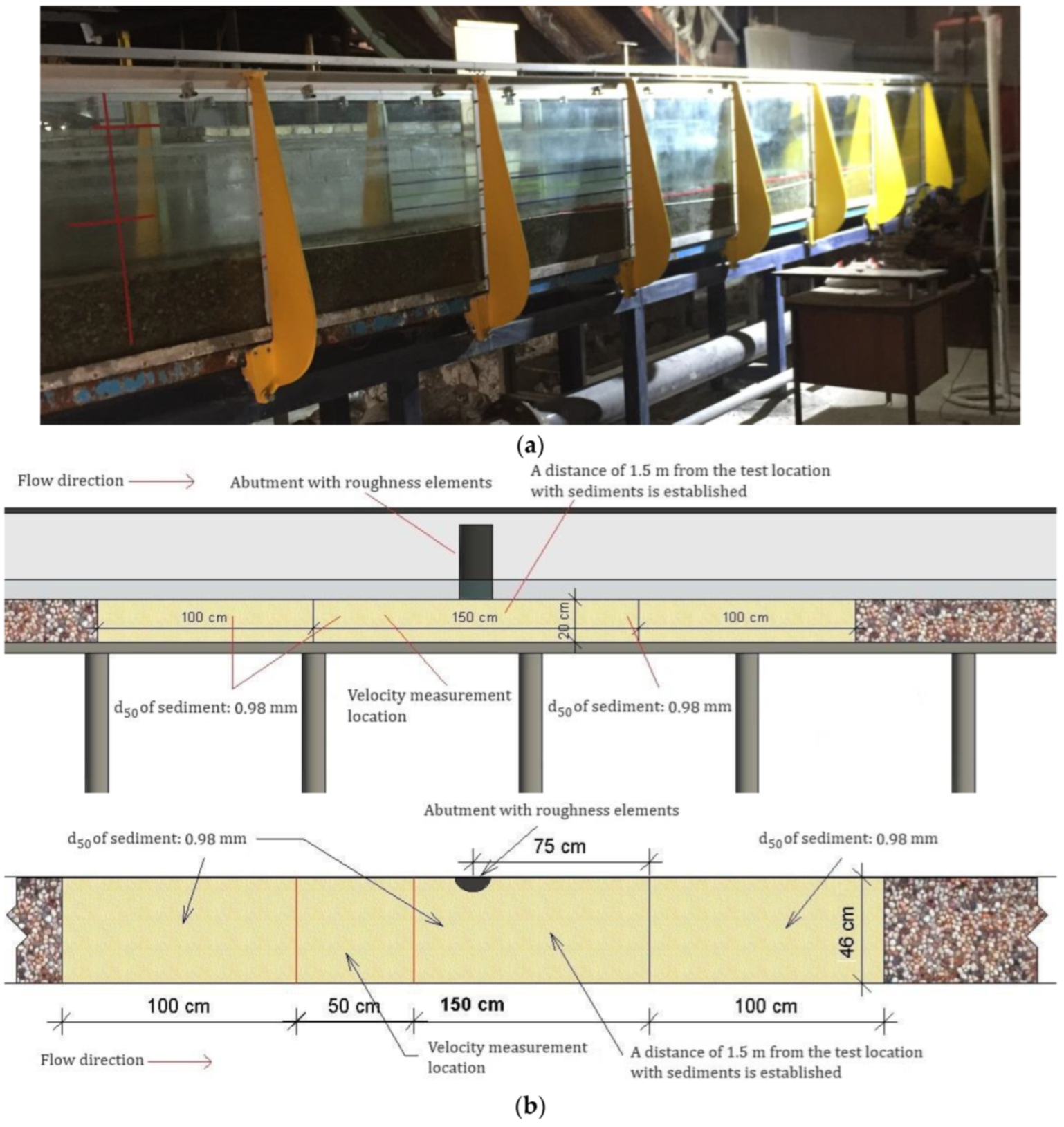
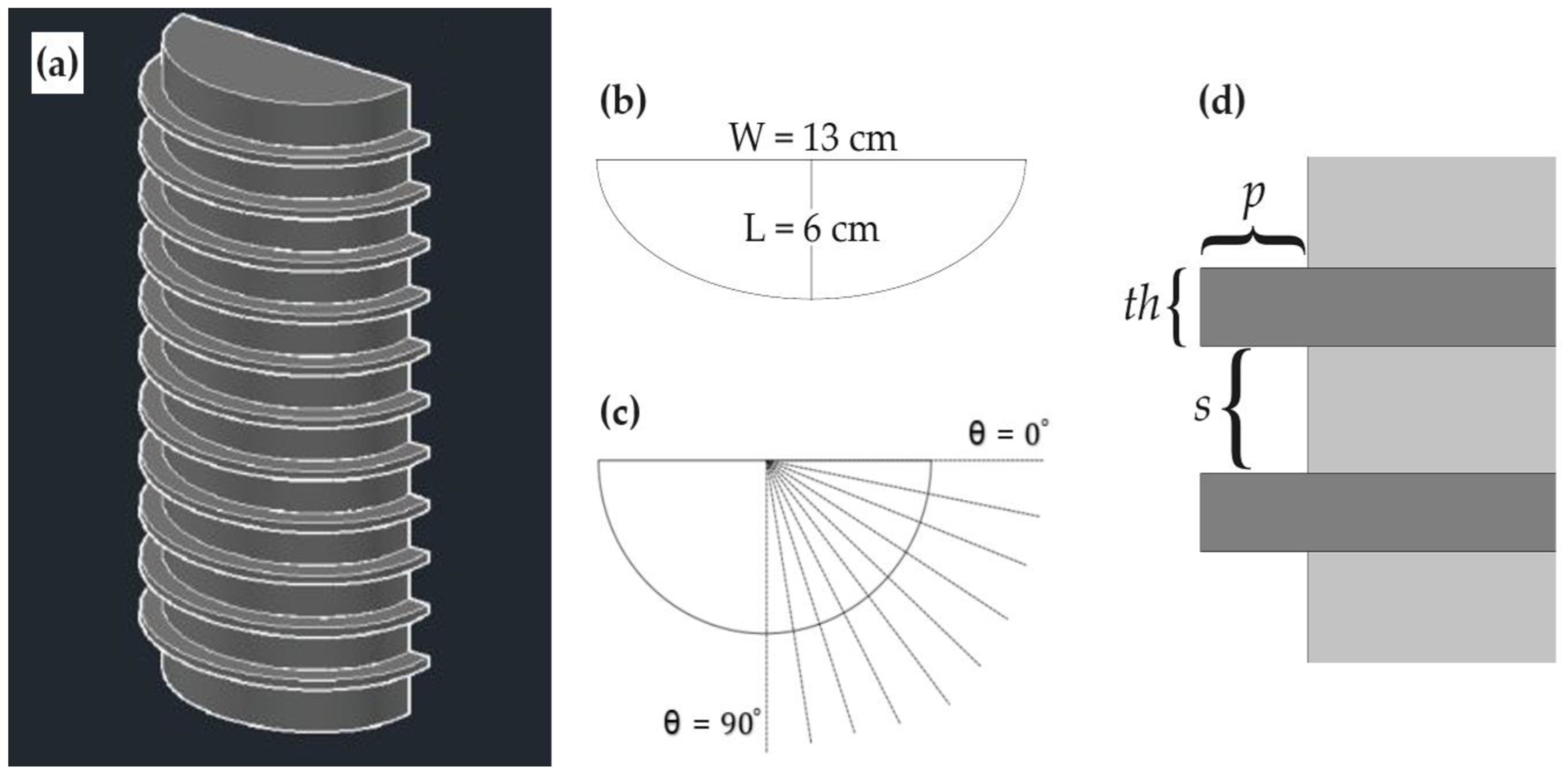
2. Materials and Methods

In this study, a plexiglass flume measuring 13 m in length, 0.46 m in width, and 1 m in height was employed. The hydraulic laboratory at the Tehran Water Research Center provided the flume, which incorporated a centrifugal pump and a piping system. The flow depth within the flume could be regulated using sliding valves. The sliding valves’ characteristics used in the experiments were determined by the parameters affecting the discharge coefficient [12]. The laboratory flume used in the experiments is shown in Figure 1. In the flume, a uniform and non-cohesive sediment with a length of one meter, and a height of 20 cm was used at a distance of nine meters from the beginning of the flume. The choice of a 20 cm thickness for the bed material was based on the consideration that the maximum scour depth was equal to 2.4 times the abutment length (L). While it is possible to increase the thickness by 30%, a 20 cm thickness was selected for the bed material [13,14,15]. The data collection for all experiments took place once the flow in the flume reached its fully developed state at 9.75 units from the entrance.
For the roughness elements on the abutment, plexiglass material was employed. The roughness elements were designed, cut, and affixed to the abutment model. Various flow depths were tested using this setup. Figure 2 provides a comprehensive visual representation of the abutment’s cross-section plan. It encompasses essential details such as specifications, the measurement ranges for scour hole depth and slope in experimental settings, and a profile view highlighting the roughness elements, all of which are elaborated upon in Table 2.
During the experiments, a limnimeter was employed to gauge the flow depth, whereas a micro-current-meter was utilized to determine the flow velocity at the channel’s centerline. To compute the vertical mean velocity for each cross-section, velocity measurements were collected at various vertical points, spanning from the bed to the water surface. Specifically, velocity data were gathered at 13 points for a depth of 15 cm, 12 points for 12 cm depth, and another 12 points for a depth of 9 cm. The velocity measurements were carried out by using a butterfly current meter (BFM002) with a horizontal axis and accuracy of ±2.5%.
The semi-elliptical models were constructed using plexiglass. Figure 2 and Table 2 provide information regarding the size and location of the roughness bulges, the initial sample, and the number of tests conducted on abutments with roughness elements.
Dimensions of the abutment were determined based on recommendations by Raudkivi and Ettema [16].
The size of the sediments used was specifically chosen to prevent the formation of ripples with a criterion of d50 > 0.7 mm [16]. Previous studies indicate that scour depths in ripple sediments are generally less significant compared to non-ripple sediments [4,16]. For bridge foundations, scour depth is not affected by sediments smaller than 1/50 of the foundation width. In this study, the approach taken is to only consider data that meet the condition L/d50 ≥ 50, ensuring that scour is not influenced by particle size [4,17].
To mitigate the non-uniform effects of sediment particles on local scour, an average particle diameter of 0.98 mm was selected, and the geometric standard deviation of particle size met the σ g = d 84 / d 16 < 1.3 condition, which considered σ g = 1.13 for all experiment runs. These criteria are aimed at reducing the impact of sediment particle non-uniformity on the equilibrium scour depth.
To maximize scour depth, it is imperative to configure the test conditions in such a way that the flow’s shear velocity approaches the threshold condition. In clear water conditions, where no sediment is present, the upstream particles must remain stable. Ensuring the stability of the particles upstream is imperative to establish the ideal flow conditions required for the initiation of scour and to facilitate the observation of the maximum scour depth.
In this study, the value of u = 0.95 u c was chosen for shear velocity. To determine the critical shear velocity for the desired depths, the Shields diagram modified by Henderson was utilized [18]. This diagram takes into account sediment particles with an average size of 0.95 mm. Additionally, the logarithmic law of velocity distribution (Equation (1)) was employed to determine the critical velocity and flow depth [15]. These approaches were used to ensure accurate determination of the necessary flow conditions for scour in the experiment.
u u = 5.75 l o g u y υ + B r  
where y is the distance from the bed; υ is the kinematic viscosity of water; Br is a constant related to bed particles of the channel; and u is the shear velocity [19]. To determine the threshold for particle movement, an experiment was conducted in the flume without the base at three different flow rates. The depth at which particle movement was observed was considered the critical depth [19]. By utilizing Equation (2) and relating the flow depths to the critical depth, the critical shear velocity was obtained. Subsequently, using Equation (1), the modified depths were determined, which encompass the comprehensive characteristics of depth, flow rate, and velocity, as presented in Table 3. In Table 3, h denotes the flow depth, Q represents the flow rate, U is the average velocity, u c represents the critical shear velocity, h is the flow depth and Fr denotes the Froude number. Furthermore, the flow in this study is characterized as hydraulically rough, with a grain Reynolds number, R e d = u d 50 υ , surpassing 100.
u c u = 5.75 log h k s + B r
where k s is the roughness parameter, which was considered as k s = d 50 ; The value of Br is approximately 8.0, determined from an average of data gathered from multiple profiles. Initially, various methods for estimating shear velocity ( u ) were compared, encompassing the measured velocity profile. The analysis concluded that these methods exhibited strong agreement. This consensus was further validated by pertinent previous studies [20].
To capture the initial rapid changes in scour depth, measurements were taken at short time intervals during the first hour of the experiment. Subsequently, measurements were recorded once every hour from the fourth hour until the conclusion of the experiment. After the experiment, additional measurements were taken along the slope to determine the upstream slope of the scour hole. This approach allowed for a comprehensive understanding of the temporal evolution of scour depth and the characterization of the scour hole’s slope.
To examine the impact of local roughness on scour depth and identify the most effective roughness dimensions in reducing scour depth, specific dimensions of roughness elements were incorporated based on the characteristics outlined in Table 2 (Figure 3). Additionally, the upstream slope of the scour hole was determined for bridge abutments with rough surfaces. Each experiment was repeated three times, with the first, second, and third experiments conducted at depths of 15 cm, 12 cm, and 9 cm, respectively. The results of these tests were compared and analyzed in three series, allowing for a comprehensive assessment and interpretation of the findings.

3. Results and Discussion

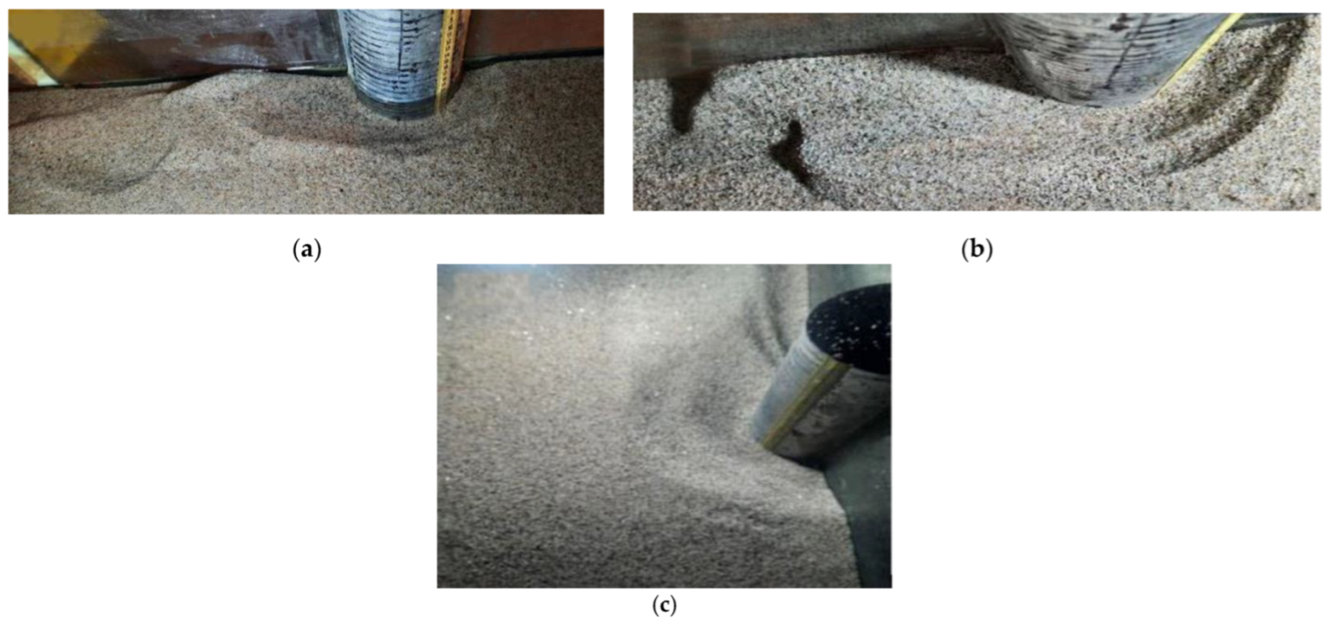
3.1. Temporal Development of Scour in the Abutment without Roughness Elements

Upon commencing the tests, a noticeable scour hole rapidly formed around the abutment, as depicted in Figure 4. This indicates the occurrence of primary vortices downstream. Laboratory observations suggest that the intensity of scour development at a depth of 9 cm is lower compared to depths of 12 cm and 15 cm. This aligns with the experimental findings reported by other researchers [21,22,23,24,25], which indicate that the maximum scour depth increases with an increase in the depth of the approaching flow. Consequently, it is expected that the scour of the abutment’s sides will be less pronounced at a depth of 9 cm compared to depths of 12 cm and 15 cm. During the initial stages of scour, the expansion and deepening of the scour hole around the abutment are more prominent [4]. The authors utilized a one-dimensional current meter that could not capture turbulence data. In another study, we employed an Acoustic Doppler Velocimeter (ADV) and encountered limitations in capturing relevant data due to reduced spacing in skimming flow conditions. The intention to adopt Particle Image Velocimetry (PIV) is driven by the desire to conduct a more extensive investigation, aiming to reveal the intricate flow patterns around the abutment.
The influence of primary vortices becomes evident during the initial stages of the test, leading to the expansion and deepening of the scour hole around the abutment. The presence of rising vortices facilitates the redirection of flow toward the back of the abutment, resulting in the deposition of sediment around the hole. As the equilibrium time approaches, the size and depth of the hole begin to decrease. Figure 4 depicts the progression of the scour hole after the equilibrium time, which is reached at 28 h. At a depth of 9 cm, the process of scour and hole formation occurs gradually compared to the other two depths (12 cm and 15 cm), due to the diminishing intensity of the flow.
Figure 5 illustrates the temporal evolution of scour around semi-elliptical bridge abutments without roughness elements. Initially, there is rapid expansion of scour in all three depths, eventually leading to a state of relative balance. The scour depth is lower at a depth of 9 cm, and as the flow depth increases to 15 cm, the scour depth also increases. Previous studies, such as Larsen (1952) and Larsen and Toch (1952), have shown that the scour depth increases with an increase in flow depth up to a value of h/L~3 [26,27]. However, for h/L > 3, the scour is primarily influenced by the flow depth. In the present research, the corresponding values for depths of h = 9 cm, h = 12 cm, and h = 15 cm were 1.5, 2, and 2.5, respectively, which were all less than 3. Also, teq = the equilibrium time of scour, which was 24 h. Several equilibrium times, namely 24 and 48 h, were tested, revealing that the predominant scour occurred within the initial seven hours. This finding aligns with the suggestion by Melville and Chiew (1999) that equilibrium is achieved when the alteration in scour depth remains below five percent of the pier diameter within 24 h [28]. It is important to note that this study focused on the smaller diameter of elliptical abutments rather than pier scour. Consequently, before commencing data collection, experiments spanned over a day, during which no significant change was observed after the initial 7 h. Additionally, the variation in scour depth after this timeframe was less than 5% of the abutment width.

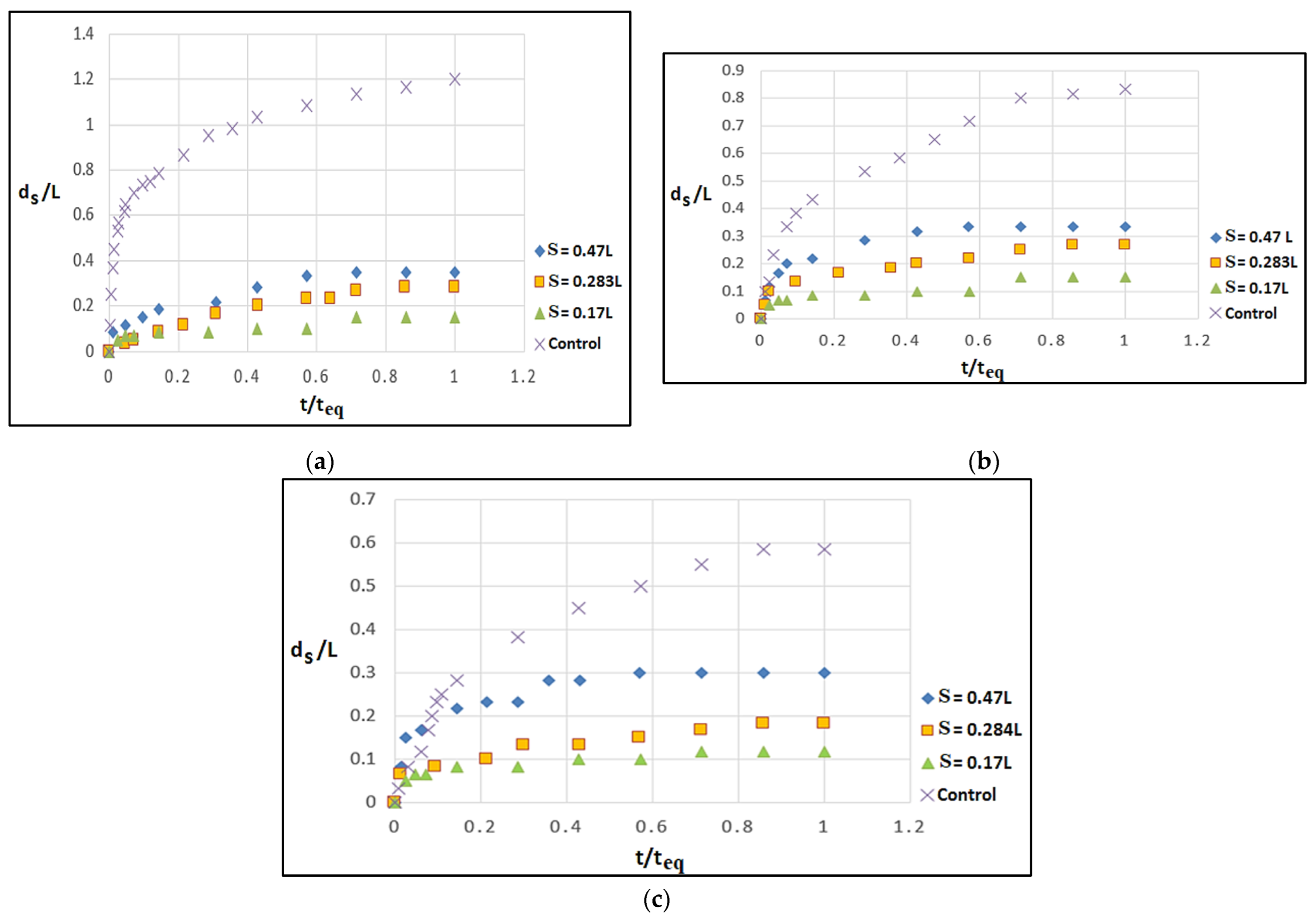
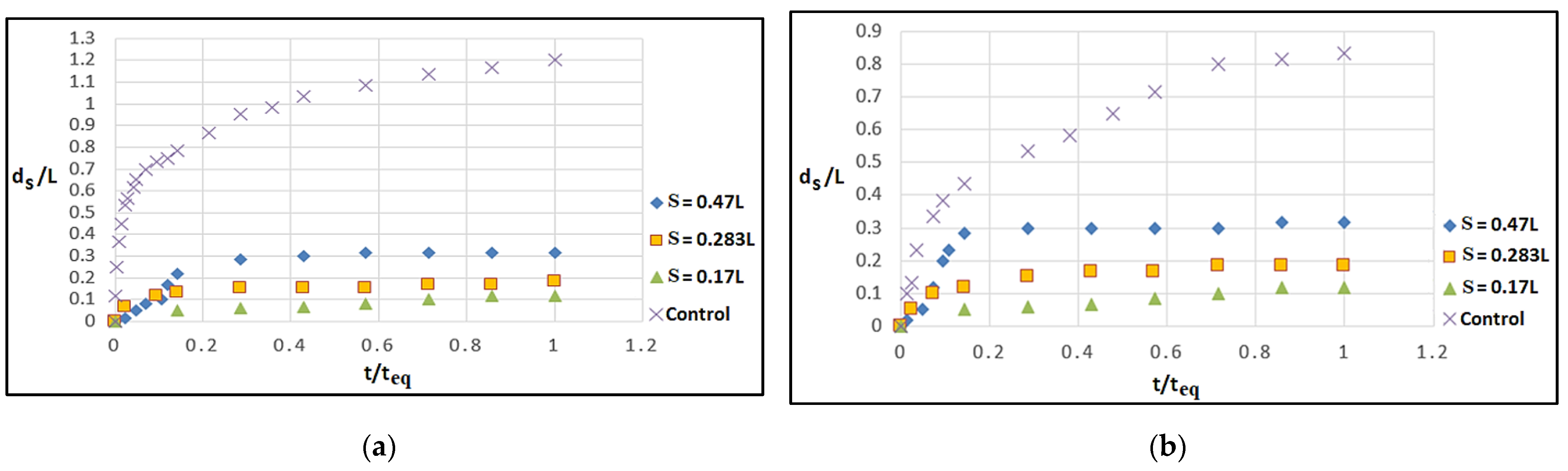
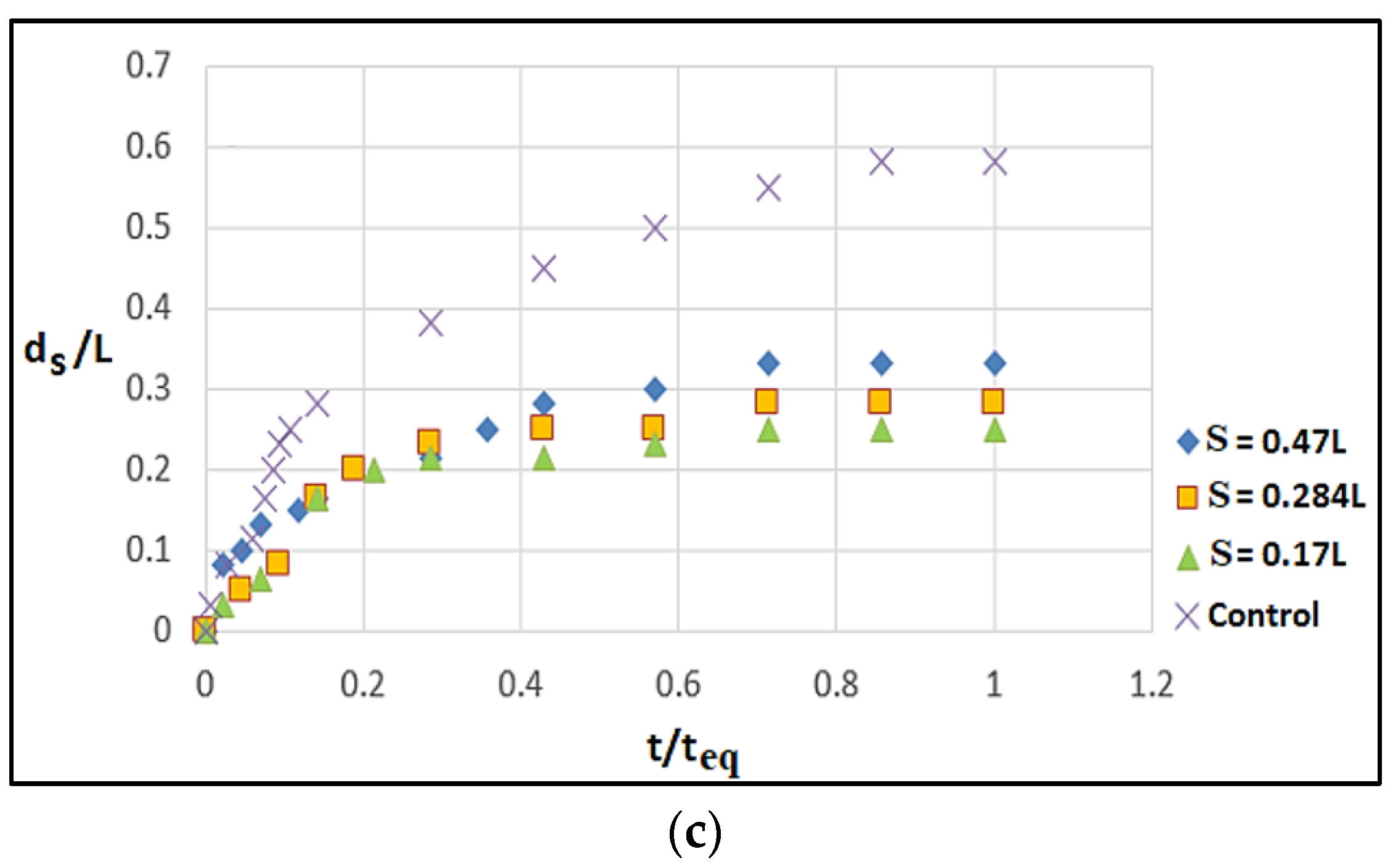
3.2. Effect of Spacing between Roughness Elements in Reducing Scour

To examine the impact of the spacing between roughness elements on reducing local scour depth, three specific spacings were considered while keeping the thickness of the roughness elements (th) constant at 0.3 cm. Figure 6 illustrates the effect of the spacing between roughness elements in reducing local scour at a ratio of p/L = 0.083 and varying spacing. Furthermore, L serves the sole purpose of facilitating the representation of dimensionless values. This research solely focuses on the variations in roughness protrusion (p) and roughness spacing (s).
As depicted in Figure 6, the presence of rough surface semi-elliptical bridge abutments effectively reduces the scour depth by diminishing the strength of primary vortices and downward flow. The intensity of scour hole development is observed to decrease as the spacing between roughness elements is reduced from 0.47 L to 0.17 L. This indicates that a higher level of roughness along the downward flow path results in a greater dissipation of flow energy downwards. To achieve the maximum effectiveness of roughness in reducing scour, it is crucial not only to select an appropriate level of roughness, but also to ensure the proper spacing between the roughness elements. The optimal spacing will depend on the specific flow conditions and characteristics of the abutment being studied.
Figure 7 demonstrates the impact of the spacing between roughness elements in reducing local scour at a ratio of p/L = 0.117 for different spacings considered in the study. On the other hand, Figure 8 provides further clarity on the process of roughness performance. In the case of p/L = 0.117, the behavior is similar to that of p/L = 0.083; however, the notable difference is that, due to the increased roughness, the final scour depth has decreased for each flow depth. This suggests that a higher level of roughness leads to a more significant reduction in scour depth, regardless of the flow depth.
The reduction in the spacing between roughness elements leads to a decrease in the equilibrium scour depth across all roughness elements. Additionally, as the roughness elements increase in size, they cause a greater deviation of the downward flow, thereby further reducing the scour process. These findings are consistent with the results of other studies, such as Radice and Davari (2014) [13], and Shahsavari et al. (2017) [14], which also observed a decrease in scour depth with a decrease in the spacing between roughness elements. Notably, the most significant decrease in scour depth was observed when the spacing between roughness elements was reduced to s/L = 0.17, and the roughness level was set at p/L = 0.17.

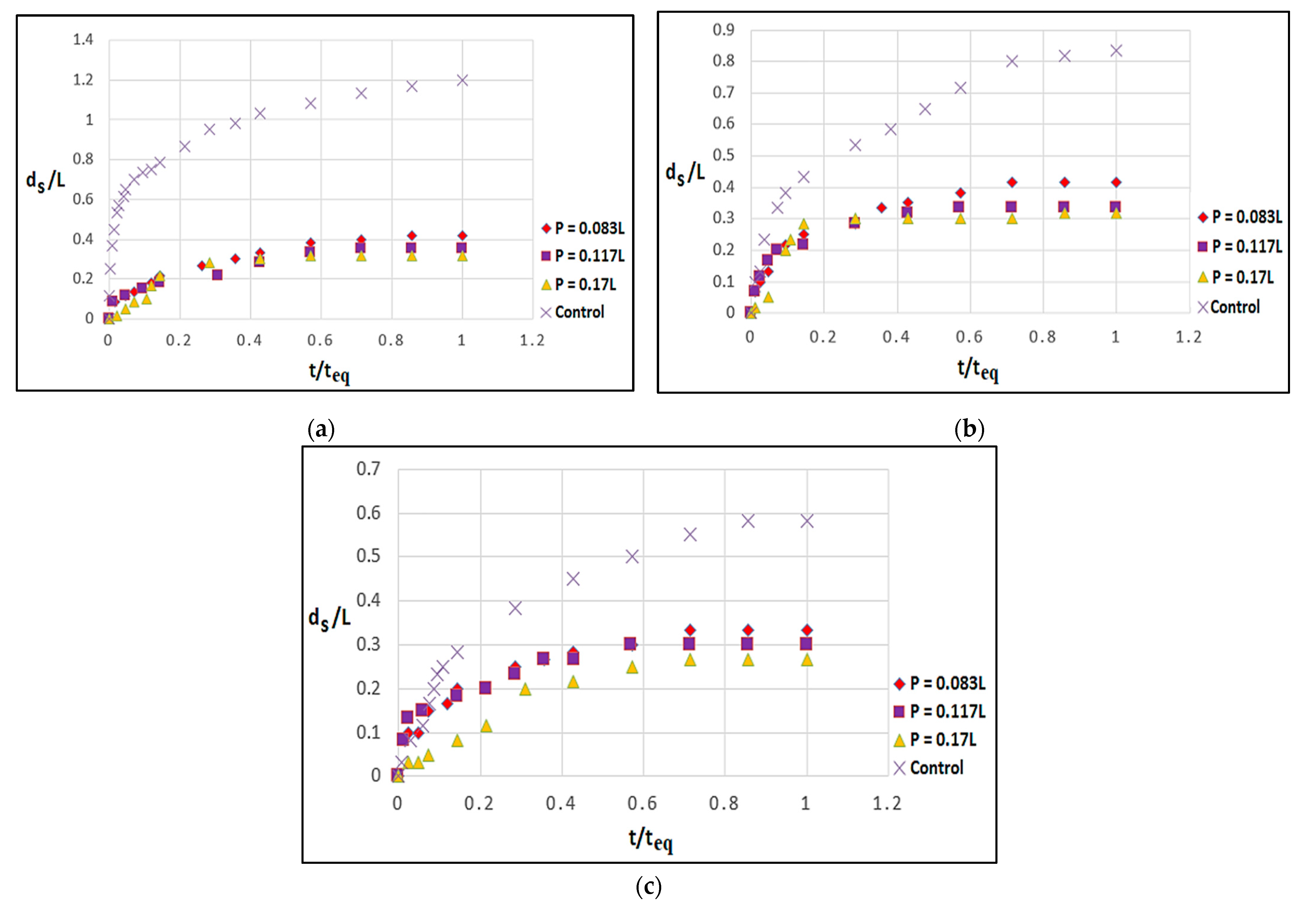
3.3. Effect of the Protrusion of Roughness Elements in Reducing Local Scour

Figure 9 depicts the effects of protrusion of roughness elements on reducing local scour at s/L = 0.47, with a constant thickness of roughness th = 0.3 cm. Figure 9 demonstrates that larger protrusion of roughness results in reduced scour compared to smaller spacing. This indicates a decrease in the energy of the downward flow. The maximum effectiveness of the protrusion of roughness is achieved when not only the highest level of roughness protrusion is selected along the downward flow path, but also the proper protrusion of roughness elements is maintained. A shorter protrusion of roughness elements increases the effective surface area of the roughness in interacting with the downward flow power [15].

3.4. Investigating the Effect of Roughness on the Upstream Slope of the Scour

Table 4 indicates that the slope values decreased for all tests with roughness elements on the abutment compared to the control test. The smallest slope of the scour hole is observed for the roughness configuration with dimensions s/L = 0.17 and p/L = 0.17. On the other hand, the roughness dimensions with p/L = 0.083 and s/L = 0.47 have higher slope values compared to other configurations, highlighting the arrangement of the roughness elements on the abutment. These findings illustrate the influence of roughness elements on altering the slope characteristics of the scour hole.
The results indicate that for all three flow depths, the slope of the scour hole initially increases from 0 degrees and reaches its maximum between angles of 50 to 70 degrees. Subsequently, the slope starts to decrease beyond 90 degrees. This behavior is attributed to the scour depth and scour being more significant between angles of 50 to 70 degrees. As a result, the scour on the sides of the hole becomes more pronounced, leading to a higher slope compared to other parts of the abutment. Also, zero values mentioned in Table 4 show the stability of the depth of the scour hole, the scour hole depth remains constant at the specific tests (θ = 50° for p = s = 1 cm, and p = 0.7 cm and s = 1 cm). The device accuracy is within the millimeter range. However, on the rough surface, an average is used rather than an exact value. This is the reason the changes reported in Table 4 are not significant.

4. Conclusions

The primary focus of this study was to investigate the impact of roughness elements and their spacing on clear-water scour at semi-elliptical bridge abutments, with a specific emphasis on uniform sediment sizes. Based on the findings of this experimental study, the following results were identified:
  • In bridge abutments that lacked a rough surface, the study observed an increase in scour depth as the flow depth increased. However, when roughness elements were present on the abutment surface, they contributed to a decrease in downflow, resulting in less scour around the structure. This reduction in scour was attributed to the weakening of adverse pressure and the primary vortices caused by the roughness elements.
  • It was observed that a small spacing between the roughness elements hindered the power of the downflow. By increasing the size of the roughness elements for shorter spacings, the downflow was deflected, thereby preventing a direct and significant impact of the flow on the bed and scour hole. As a result, the flow strength around the abutment was reduced.
  • The study revealed a notable correlation between the presence of roughness elements on the abutment surface and the spacing between them in relation to the scour around the bridge abutments. An observation was made that as the ratio of the spacing between roughness elements (s) to the size of the protrusion of elements (p) increased, there was a noticeable reduction in the impact of roughness on the scour. Specifically, at a given depth of flow and protrusion of roughness elements (p), when the spacing between roughness elements (s) approached a value closer to the ratio of the protrusion of roughness elements, a decrease in scour depth was observed.
  • In the presence of roughness, the slope of the scour hole exhibited a distinctive pattern, as observed in the study. Initially, it commenced at a 0-degree angle and gradually increased, reaching angles ranging between 50 and 70 degrees. This range corresponded to the peak scour depth, indicating the most significant scour and this progressing in the slope of the scour hole causes the steeper slope at these angle ranges. Once the peak was reached, the slope of the scour hole began to decrease as the angle approached 90 degrees.

Author Contributions

Conceptualization, H.A.; methodology, H.A.; software, A.R. and M.N.-S.; resources, H.A.; data curation, A.R., H.A., S.S., M.N.-S. and R.A.; writing—original draft preparation, A.R.; writing—review and editing, A.R., H.A., S.S., M.N.-S., R.A. and M.K.; supervision, H.A., M.N.-S. and M.K. All authors have read and agreed to the published version of the manuscript.

Funding

This research received no external funding.

Data Availability Statement

The data are available upon request.

Conflicts of Interest

The authors declare no conflict of interest.

References

  1. Pourmansouri, R. Controlling the Scouring Occurrence of the Bridge by Implanting the Submerged Plates with Different Angles. Master’s Thesis, Chamran University of Ahwaz, Khuzestan, Iran, 2017. [Google Scholar]
  2. Shirole, A.M.; Holt, R.C. Planning for a comprehensive bridge safety assurance program. Transp. Res. Rec. 1991, 1290, 39–50. [Google Scholar]
  3. Ahmed, F.; Nallamuthu, R. Flow around bridge piers. J. Hydraul. Eng. 1998, 124, 288–300. [Google Scholar] [CrossRef]
  4. Ettema, R. Scour at Bridge Piers—Report No 216; School of Engineering, University of Auckland: Auckland, New Zealand, 1980. [Google Scholar]
  5. Chiew, Y.M. Local Scour at Bridge Piers. Ph.D. Thesis, University of Auckland, Auckland, New Zealand, 1984. [Google Scholar]
  6. Kwan, T.F. Study of Abutment Scour; No. 328; School of Engineering Report; University of Auckland: Auckland, New Zealand, 1984. [Google Scholar]
  7. Chiew, Y.M. Scour protection at bridge piers. J. Hydraul. Eng. 1992, 118, 1260–1269. [Google Scholar] [CrossRef]
  8. Melville, B.W. Local scour at bridge abutments. J. Hydraul. Eng. 1992, 118, 615–631. [Google Scholar] [CrossRef]
  9. Afzal, M.S.; Bihs, H.; Kumar, L. Computational fluid dynamics modeling of abutment scour under steady current using the level set method. Int. J. Sediment Res. 2020, 35, 355–364. [Google Scholar] [CrossRef]
  10. Dey, S.; Sumer, B.M.; Fredsøe, J. Control of scour at vertical circular piles under waves and current. J. Hydraul. Eng. 2006, 132, 270–279. [Google Scholar] [CrossRef]
  11. Radice, A.; Oskars, L. On flow-altering countermeasures for scour at vertical-wall abutment. Arch. Hydro-Eng. Environ. Mech. 2012, 59, 137–153. [Google Scholar]
  12. Daneshfaraz, R.; Norouzi, R.; Ebadzadeh, P.; Kuriqi, A. Influence of sill integration in labyrinth sluice gate hydraulic performance. Innov. Infrastruct. Solut. 2023, 8, 118. [Google Scholar] [CrossRef]
  13. Radice, A.; Vahid, D. Roughening elements as abutment scour countermeasures. J. Hydraul. Eng. 2014, 140, 06014014. [Google Scholar] [CrossRef]
  14. Shahsavari, H.; Manouchehr, H.; Mohammad, M. Simultaneous Effect of Collar and Roughness on Reducing and Controlling the Local Scour around Bridge Abutment. Acta Univ. Agric. Et Silvic. Mendel. Brun. 2017, 65, 52. [Google Scholar] [CrossRef]
  15. Shahsavari, H. Investigation of the Effect of Local Roughness in Controlling and Reducing the Local Scouring of the Bridge Abutment. Master’s Thesis, Isfahan University of Technology, Khomeyni Shahr, Iran, 2014. [Google Scholar]
  16. Raudkivi, A.J.; Ettema, R. Clear-water scour at cylindrical piers. J. Hydraul. Eng. 1983, 109, 338–350. [Google Scholar] [CrossRef]
  17. Ettema, R.; Gokhan, K.; Marian, M. Similitude of large-scale turbulence in experiments on local scour at cylinders. J. Hydraul. Eng. 2006, 132, 33–40. [Google Scholar] [CrossRef]
  18. Henderson, F.M. Open Channel Flow; Professor of Civil Engineering, University of Canterbury: Christchurch, New Zealand; Macmillan Publishing Co., Inc.: New York, NY, USA, 1966. [Google Scholar]
  19. Arneson, L.A.; Zevenbergen, L.W.; Lagasse, P.F.; Clopper, P.E. Evaluating Scour at Bridges, 5th ed.; FHWA Report: FHWA-HIF-12-003 HEC-18; Federal Highway Administration. Office of Technology Applications: Washington, DC, USA, 1995. [Google Scholar]
  20. Graf, W.H.; Altinakar, M.S. Fluvial Hydraulics: Flow and Transport Processes in Channels of Simple Geometry; Wiley: New York, NY, USA, 1998. [Google Scholar]
  21. Follett, E.M.; Nepf, H.M. Sediment patterns near a model patch of reedy emergent vegetation. Geomorphology 2012, 179, 141–151. [Google Scholar] [CrossRef]
  22. Gill, M.A. Erosion of sand beds around spur dikes. J. Hydraul. Div. 1972, 98, 1587–1602. [Google Scholar] [CrossRef]
  23. Kandasamy, J.K. Abutment Scour; Rep. No. 458; School of Engineering, University of Auckland: Auckland, New Zealand, 1989. [Google Scholar]
  24. Dongol, D.M.S. Local Scour at Bridge Abutments. Ph.D. Thesis, The University of Auckland, Auckland, New Zealand, 1993. [Google Scholar]
  25. Wong, W.H. Scour at Bridge Abutments; Rep. No. 275; School of Engineering, University of Auckland: Auckland, New Zealand, 1982. [Google Scholar]
  26. Laursen, E.M. 1952 Observations on the nature of scour. In Proceedings of the 5th Hydraulic Conference; University of Iowa: Iowa City, IA, USA, 1952; pp. 179–197. [Google Scholar]
  27. Laursen, E.M.; Toch, A. Scour around Bridge Piers and Abutments; Iowa Highway Research Board: Ames, IA, USA, 1956; Volume 4. [Google Scholar]
  28. Melville, B.W.; Chiew, Y.M. Time scale for local scour at bridge piers. J. Hydraul. Eng. 1999, 125, 59–65. [Google Scholar] [CrossRef]
Figure 1. (a) The laboratory flume, and (b) the experiment area’s plan view.
Fluids 08 00306 g001
Figure 2. (a) 3-D view of the abutment with roughness elements; (b) Abutment dimensions; (c) Angle range of measuring the depth and slope of the scour hole in the experiments; (d) Roughness elements on the abutment, and their protrusion (p), thickness (th), and spacing (s).
Fluids 08 00306 g002
Figure 3. Example (s = 0.283 L and p = 0.117 L) of how the height of points was measured.
Fluids 08 00306 g003
Figure 4. Scour pit at the end of the experiment, for the following flow depths: (a) h = 15 cm, (b) h = 12 cm, and, (c) h = 9 cm.
Fluids 08 00306 g004
Figure 5. Temporal development of scour (ds) around the abutment at three depths (h = 9 cm, 12 cm, and 15 cm).
Fluids 08 00306 g005
Figure 6. The effect of the spacing between the roughness elements on the temporal development of the local scour depth (p/L = 0.083); (a) h = 15 cm, (b) h = 12 cm, (c) h = 9 cm.
Fluids 08 00306 g006
Figure 7. The effect of the spacing between the roughness elements on the temporal development of the local scour depth (p/L = 0.117); (a) h = 15 cm, (b) h = 12 cm, (c) h = 9 cm.
Fluids 08 00306 g007
Figure 8. The effect of the spacing between the roughness elements on the temporal development of the local scour depth (p/L = 0.17); (a) h = 15 cm, (b) h = 12 cm, (c) h = 9 cm.
Fluids 08 00306 g008aFluids 08 00306 g008b
Figure 9. The impact of the occurrence of roughness on the temporal development of scour (s/L = 0.47); (a) h = 15 cm, (b) h = 12 cm, (c) h = 9 cm.
Fluids 08 00306 g009
Table 1. Bridge failure statistics in Iran [1].
YearNumber of Failed Bridges
1952–196078
1972–1980648
1982–199097
1992–20005724
2002–20069392
Table 2. Roughness dimensions.
Experiment NumberRoughness Thickness (th, cm)Roughness Protrusion (p, cm)Roughness Spacing (s, cm)
1---
20.30.51
30.30.71
40.311
50.30.51.7
60.30.71.7
70.311.7
80.30.52.8
90.30.72.8
100.312.8
Table 3. A summary of flow parameters.
h (cm) Q   ( m 3 / s ) U (m/s)
u / u c   =   0.95
u c   ( m / s ) Fr   =   u g h
90.0110.2640.02500.28
120.0150.2750.02550.26
150.0190.2890.02580.24
Table 4. The slope of the pit upstream of the control abutment and rough abutment, for three case depths.
p, s (cm)s/ph (cm)θ = 50°θ = 60°θ = 70°
p = s = 0 150.68350.68350.6835
-120.64710.64710.6471
90.54120.54120.5412
p = 0.5, s = 2.8 150.50920.50920.5092
5.6120.50110.50110.5011
90.47670.47670.4767
p = 0.5, s = 1.7 150.46830.46830.4683
3.4120.46210.46210.4621
90.40730.40730.4073
p = 0.7, s = 2.8 150.42740.42740.4274
4.0120.42030.42030.4203
90.43880.43880.4388
p = s = 1 150.00.11610.1161
1120.00.11420.1142
90.00.1010.101
p = 1, s = 2.8 150.38960.38960.3896
2.8120.38920.38920.3892
90.4130.4130.413
p = 1, s = 1.7 150.19970.19970.1997
1.7120.19970.19970.1997
90.15930.15930.1593
p = 0.7, s = 1.7 150.24570.24570.2457
2.43120.24010.24010.2401
90.16140.16140.1614
p = 0.7, s = 1 150.00.1380.138
1.43120.00.1360.136
90.00.13020.1302
p = 0.5, s = 1 150.31640.31640.3164
2.0120.31260.31260.3126
90.29520.29520.2952
Disclaimer/Publisher’s Note: The statements, opinions and data contained in all publications are solely those of the individual author(s) and contributor(s) and not of MDPI and/or the editor(s). MDPI and/or the editor(s) disclaim responsibility for any injury to people or property resulting from any ideas, methods, instructions or products referred to in the content.

