

Formation and Behaviour of Active Droplets and Bubbles in a Magnetic Fluid in an Inhomogeneous Magnetic Field


Abstract
1. Introduction
2. Materials and Methods
3. Results
4. Discussion
Author Contributions
Funding
Data Availability Statement
Conflicts of Interest
References
- Erb, R.M.; Martin, J.J.; Soheilian, R.; Pan, C.; Barber, J.R. Actuating soft matter with magnetic torque. Adv. Funct. Mater. 2016, 26, 3859–3880. [Google Scholar] [CrossRef]
- Wu, S.; Hu, W.; Ze, Q.; Sitti, M.; Zhao, R. Multifunctional magnetic soft composites: A review. Multifunct. Mater. 2020, 3, 042003. [Google Scholar] [CrossRef] [PubMed]
- Ku, K.H.; Li, J.; Yoshinaga, K.; Swager, T.M. Dynamically reconfigurable, multifunctional emulsions with controllable structure and movement. Adv. Mater. 2019, 31, 1905569. [Google Scholar] [CrossRef]
- Vékás, L. Ferrofluids and magnetorheological fluids. In Advances in Science and Technology; Trans Tech Publications Ltd.: Bäch, Switzerland, 2008; Volume 54, pp. 127–136. [Google Scholar] [CrossRef]
- Torres-Díaz, I.; Rinaldi, C. Recent progress in ferrofluids research: Novel applications of magnetically controllable and tunable fluids. Soft Matter 2014, 10, 8584–8602. [Google Scholar] [CrossRef] [PubMed]
- Genc, S.; Derin, B. Synthesis and rheology of ferrofluids: A review. Curr. Opin. Chem. Eng. 2014, 3, 118–124. [Google Scholar] [CrossRef]
- Joseph, A.; Mathew, S. Ferrofluids: Synthetic strategies, stabilization, physicochemical features, characterization, and applications. ChemPlusChem 2014, 79, 1382–1420. [Google Scholar] [CrossRef]
- Zhang, X.; Sun, L.; Yu, Y.; Zhao, Y. Flexible ferrofluids: Design and applications. Adv. Mater. 2019, 31, 1903497. [Google Scholar] [CrossRef]
- Socoliuc, V.; Avdeev, M.V.; Kuncser, V.; Turcu, R.; Tombácz, E.; Vekas, L. Ferrofluids and bio-ferrofluids: Looking back and stepping forward. Nanoscale 2022, 14, 4786–4886. [Google Scholar] [CrossRef]
- Rosensweig, R.E. Ferrohydrodynamics; Courier Corporation: North Chelmsford, MA, USA, 1985; 348p. [Google Scholar]
- Berkovsky, B.M.; Medvedev, V.F.; Krakov, M.S. Magnetic Fluids: Engineering Applications; Oxford University Press: Oxford, UK; New York, NY, USA, 1993; 243p. [Google Scholar]
- Papell, S.S. Low Viscosity Magnetic Fluid Obtained by the Colloidal Suspension of Magnetic Particles; MPK: Luxembourg, 1965. [Google Scholar]
- Odenbach, S. (Ed.) Colloidal Magnetic Fluids: Basics, Development and Application of Ferrofluids; Lect. Notes Phys. 763; Springer: Berlin/Heidelberg, Germany, 2009; 429p. [Google Scholar] [CrossRef]
- Yerin, C.V. Particles size distribution in diluted magnetic fluids. J. Magn. Magn. Mater. 2017, 431, 27–29. [Google Scholar] [CrossRef]
- Cao, Q.; Han, X.; Li, L. Configurations and control of magnetic fields for manipulating magnetic particles in microfluidic applications: Magnet systems and manipulation mechanisms. Lab A Chip 2014, 14, 2762–2777. [Google Scholar] [CrossRef]
- Polunin, V.M.; Tantsyura, A.O.; Storozhenko, A.M.; Ryapolov, P.A. Study of demagnetizing field induced by a sound wave. Acoust. Phys. 2013, 59, 662–666. [Google Scholar] [CrossRef]
- Ivanov, A.S.; Pshenichnikov, A.F.; Khokhryakova, C.A. Floating of solid non-magnetic bodies in magnetic fluids: Comprehensive analysis in the framework of inductive approach. Phys. Fluids 2020, 32, 112007. [Google Scholar] [CrossRef]
- Zakinyan, A.R.; Zakinyan, A.A. Rotating field induced torque on ferrofluid emulsion with deformable dispersed phase microdrops. Sens. Actuators A Phys. 2020, 314, 112347. [Google Scholar] [CrossRef]
- Bohara, R.A.; Thorat, N.D.; Pawar, S.H. Role of functionalization: Strategies to explore potential nano-bio applications of magnetic nanoparticles. RSC Adv. 2016, 6, 43989–44012. [Google Scholar] [CrossRef]
- Ali, A.; Shah, T.; Ullah, R.; Zhou, P.; Guo, M.; Ovais, M.; Rui, Y. Review on recent progress in magnetic nanoparticles: Synthesis, characterization, and diverse applications. Front. Chem. 2021, 9, 629054. [Google Scholar] [CrossRef]
- Kianfar, E. Magnetic nanoparticles in targeted drug delivery: A review. J. Supercond. Nov. Magn. 2021, 34, 1709–1735. [Google Scholar] [CrossRef]
- Shah, A.; Aftab, S.; Nisar, J.; Ashiq, M.N.; Iftikhar, F.J. Nanocarriers for targeted drug delivery. J. Drug Deliv. Sci. Technol. 2021, 62, 102426. [Google Scholar] [CrossRef]
- Li, X.; Li, W.; Wang, M.; Liao, Z. Magnetic nanoparticles for cancer theranostics: Advances and prospects. J. Control Release 2021, 335, 437–448. [Google Scholar] [CrossRef]
- Chouhan, R.S.; Horvat, M.; Ahmed, J.; Alhokbany, N.; Alshehri, S.M.; Gandhi, S. Magnetic nanoparticles—A multifunctional potential agent for diagnosis and therapy. Cancers 2021, 13, 2213. [Google Scholar] [CrossRef]
- Liu, X.; Tian, Y.; Jiang, L. Manipulating dispersions of magnetic nanoparticles. Nano Lett. 2021, 21, 2699–2708. [Google Scholar] [CrossRef]
- Martínez-Pedrero, F. Static and dynamic behavior of magnetic particles at fluid interfaces. Adv. Colloid Interface Sci. 2020, 284, 102233. [Google Scholar] [CrossRef] [PubMed]
- Zentner, C.A.; Concellón, A.; Swager, T.M. Controlled movement of complex double emulsions via interfacially confined magnetic nanoparticles. ACS Cent. Sci. 2020, 6, 1460–1466. [Google Scholar] [CrossRef] [PubMed]
- Li, X.; Yu, P.; Niu, X.; Yamaguchi, H.; Li, D. Non-contact manipulation of nonmagnetic materials by using a uniform magnetic field: Experiment and simulation. J. Magn. Magn. Mater. 2020, 497, 165957. [Google Scholar] [CrossRef]
- Dunne, P.; Adachi, T.; Dev, A.A.; Sorrenti, A.; Giacchetti, L.; Bonnin, A.; Hermans, T.M. Liquid flow and control without solid walls. Nature 2020, 581, 58–62. [Google Scholar] [CrossRef]
- Zhou, Y.; Xuan, X. Diamagnetic particle separation by shape in ferrofluids. Appl. Phys. Lett. 2016, 109, 102405. [Google Scholar] [CrossRef]
- Boev, M.L.; Polunin, V.M.; Ryapolov, P.A.; Bashtovoi, V.G.; Reks, A.G.; Kazakov, Y.B.; Aref’eva, T.A. Instability of the flow of a magnetic liquid pushing down an air cavity. Russ. Phys. J. 2015, 57, 1348–1355. [Google Scholar] [CrossRef]
- Polunin, V.M.; Ryapolov, P.A.; Ryabtsev, K.S.; Kobelev, N.S.; Shabanova, I.A.; Yushin, V.V.; Postnikov, E.B. Elasticity of an air cavity in a magnetic fluid on an annular magnet segment with changing magnetic field sign. Russ. Phys. J. 2018, 61, 1347–1357. [Google Scholar] [CrossRef]
- Ryapolov, P.A.; Sokolov, E.A.; Postnikov, E.B. Behavior of a gas bubble separating from a cavity formed in magnetic fluid in an inhomogeneous magnetic field. J. Magn. Magn. Mater. 2022, 549, 169067. [Google Scholar] [CrossRef]
- Sokolov, E.; Vasilyeva, A.; Kalyuzhnaya, D.; Ryapolov, P. Dynamics of nonmagnetic inclusions in a microchannel with a magnetic fluid in an inhomogeneous magnetic field. AIP Adv. 2022, 12, 035333. [Google Scholar] [CrossRef]
- Battat, S.; Weitz, D.A.; Whitesides, G.M. Nonlinear phenomena in microfluidics. Chem. Rev. 2022, 122, 6921–6937. [Google Scholar] [CrossRef] [PubMed]
- Huang, G.; Li, M.; Yang, Q.; Li, Y.; Liu, H.; Yang, H.; Xu, F. Magnetically actuated droplet manipulation and its potential biomedical applications. ACS Appl. Mater. Interfaces 2017, 9, 1155–1166. [Google Scholar] [CrossRef] [PubMed]
- Wu, X.; Streubel, R.; Liu, X.; Kim, P.Y.; Chai, Y.; Hu, Q.; Russell, T.P. Ferromagnetic liquid droplets with adjustable magnetic properties. Proc. Natl. Acad. Sci. USA 2021, 118, e2017355118. [Google Scholar] [CrossRef] [PubMed]
- Liu, X.; Kent, N.; Ceballos, A.; Streubel, R.; Jiang, Y.; Chai, Y.; Russell, T.P. Reconfigurable ferromagnetic liquid droplets. Science 2019, 365, 264–267. [Google Scholar] [CrossRef] [PubMed]
- Li, Q.Z.; Lu, Z.L.; Zhou, D.; Niu, X.D.; Guo, T.Q.; Du, B.C.; Li, Y. Magnetic field-induced self-assembly of multiple nonmagnetic bubbles inside ferrofluid. Phys. Fluids 2021, 33, 103307. [Google Scholar] [CrossRef]
- Fan, X.; Dong, X.; Karacakol, A.C.; Xie, H.; Sitti, M. Reconfigurable multifunctional ferrofluid droplet robots. Proc. Natl. Acad. Sci. USA 2020, 117, 27916–27926. [Google Scholar] [CrossRef]
- Wu, J.; Pei, L.; He, X.; Cui, Y.; Xuan, S.; Gong, X. Study on nonlinear magnetic droplets in a flow-focusing generator. Appl. Phys. Lett. 2019, 115, 031903. [Google Scholar] [CrossRef]
- Zhang, Y.; Jiang, S.; Hu, Y.; Wu, T.; Zhang, Y.; Li, H.; Chu, J. Reconfigurable magnetic liquid metal robot for high-performance droplet manipulation. Nano Lett. 2022, 22, 2923–2933. [Google Scholar] [CrossRef]
- Kichatov, B.; Korshunov, A.; Sudakov, V.; Petrov, O.; Gubernov, V.; Korshunova, E.; Kiverin, A. Magnetic Nanomotors in Emulsions for Locomotion of Microdroplets. ACS Appl. Mater. Interfaces 2022, 14, 10976–10986. [Google Scholar] [CrossRef]
- Chen, L.; Yang, C.; Xiao, Y.; Yan, X.; Hu, L.; Eggersdorfer, M.; Ye, F. Millifluidics, microfluidics, and nanofluidics: Manipulating fluids at varying length scales. Mater. Today Nano 2021, 16, 100136. [Google Scholar] [CrossRef]
- Yamasaki, H.; Kishimoto, T.; Tazawa, T.; Yamaguchi, H. Dynamic behavior of gas bubble detached from single orifice in magnetic fluid. J. Magn. Magn. Mater. 2020, 501, 166446. [Google Scholar] [CrossRef]
- Beketova, E.S.; Nechaeva, O.A.; Mkrtchyan, V.D.; Zakinyan, A.R.; Dikanskii, Y.I. Structural Transformations in Magnetic Emulsions upon Their Interaction with an Alternating Electric Field. Colloid J. 2021, 83, 189–202. [Google Scholar] [CrossRef]


| MF1.1 | MF1.2 | MF1.3 | MF1.4 | MF2.1 | MF2.2 | MF3.1 | MF3.2 | MF4.1 | |
|---|---|---|---|---|---|---|---|---|---|
| Base Fluid | Water | Kerosene | Mineral Oil | Synthetic Oil | |||||
| ρ, kg/m3 | 1212 | 1082 | 1056 | 1026 | 1382 | 936 | 1270 | 1018 | 1050 |
| φ, % | 4.9 | 1.9 | 1.3 | 0.72 | 14.2 | 3.63 | 10.31 | 4.26 | 4.81 |
| Ms, kA/m | 21.7 | 11 | 6.98 | 3.7 | 49 | 12,5 | 39.9 | 17 | 27.3 |
| η, mPa∙s | 5.6 | 2.15 | 1.65 | 1.5 | 240 | 2.45 | 594 | 69 | 650 |
| PMS 5 | PMS 100 | Oil | Kerosene | Water | |
|---|---|---|---|---|---|
| η, mPa∙s | 5 | 85 | 37 | 1,3 | 1 |
| ρ, kg/m3 | 918 | 966 | 882 | 783 | 1000 |
| MF | Supplied Non-Magnetic Phase | Result |
|---|---|---|
| MF 1.1 | PMS 5 | The formation and separation of droplets from the cavity do not occur |
| MF 1.1 | PMS 100 | |
| MF 1.1 | Oil | |
| MF 1.1 | Kerosene | |
| MF 2.1 | Water |
| MF | Liquid in the Cavity and on the Surface MF | Supply Phase | Dynamics of Multi-Phase Magnetic System | Result | |||
|---|---|---|---|---|---|---|---|
| MF1.1 | PMS 5 | Air |  |  |  |  | Active bubble in the membrane MF |
| MF1.1 | PMS 100 | Air |  |  |  |  | Active bubble in the membrane MF |
| MF1.1 | Oil | Air |  |  |  |  | Active bubble in the membrane MF |
| MF1.2 | Oil | Air |  |  |  |  | Active bubble in the membrane MF |
| MF1.3 | Oil | Air |  |  |  |  | Active bubble in the membrane MF |
| MF4.1 | Water | Water |  |  |  |  | Bubble in the membrane MF |
| MF1.3 | Oil | Oil |  |  |  |  | Jet stream formation |
| MF2.1 | Water | Oil |  |  |  |  | Jet stream formation |
| MF | Bubbles Trajectory | Self-Organization | |
|---|---|---|---|
| MF1.1 | Without magnetic field |  |  |
| Under the influence of a magnetic field |  |  | |
| MF1.2 | Without magnetic field |  |  |
| Under the influence of a magnetic field |  |  | |
| MF1.3 | Without magnetic field |  |  |
| Under the influence of a magnetic field |  |  | |
| MF1.4 | Without magnetic field |  |  |
| Under the influence of a magnetic field |  |  | |
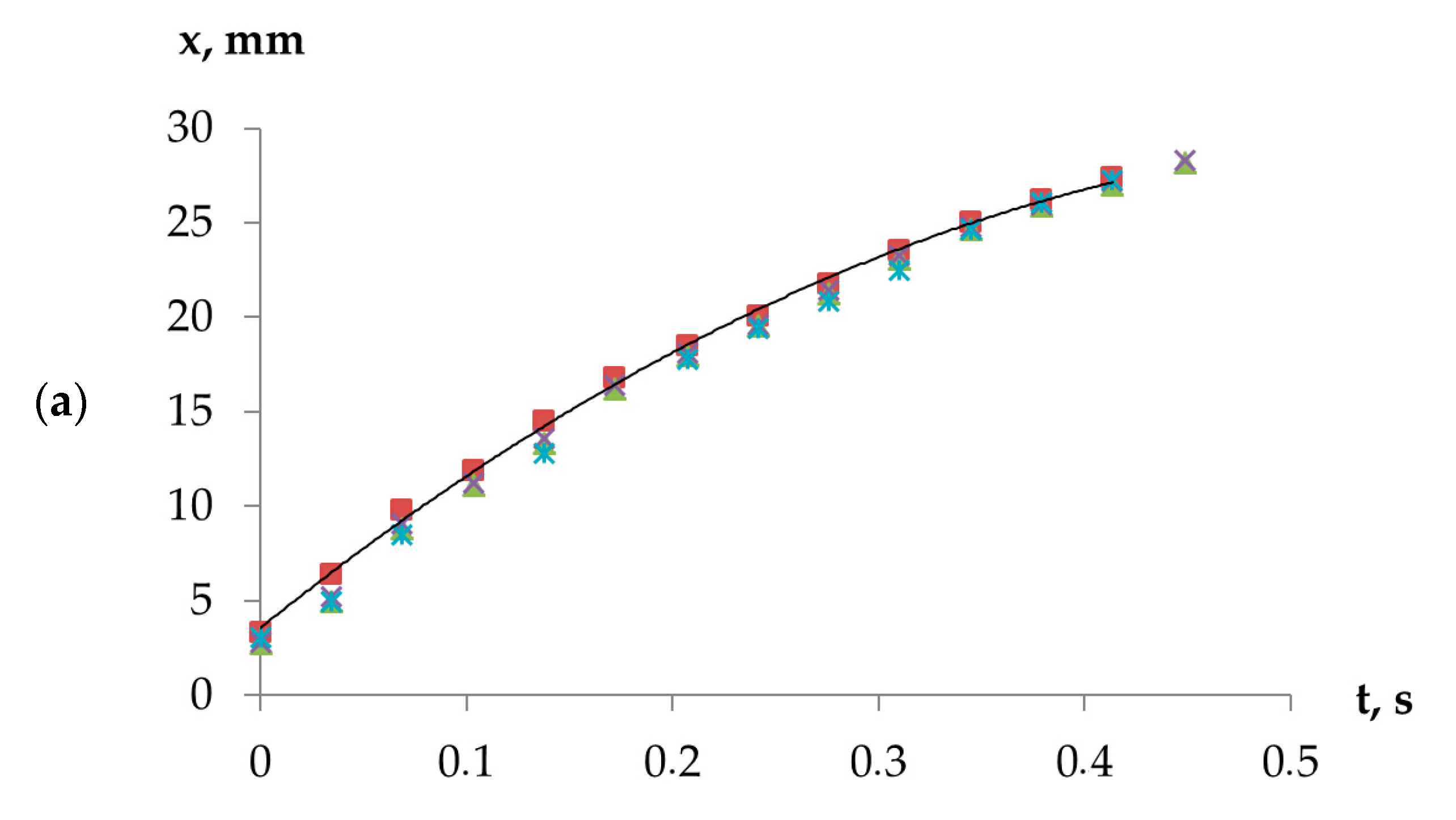
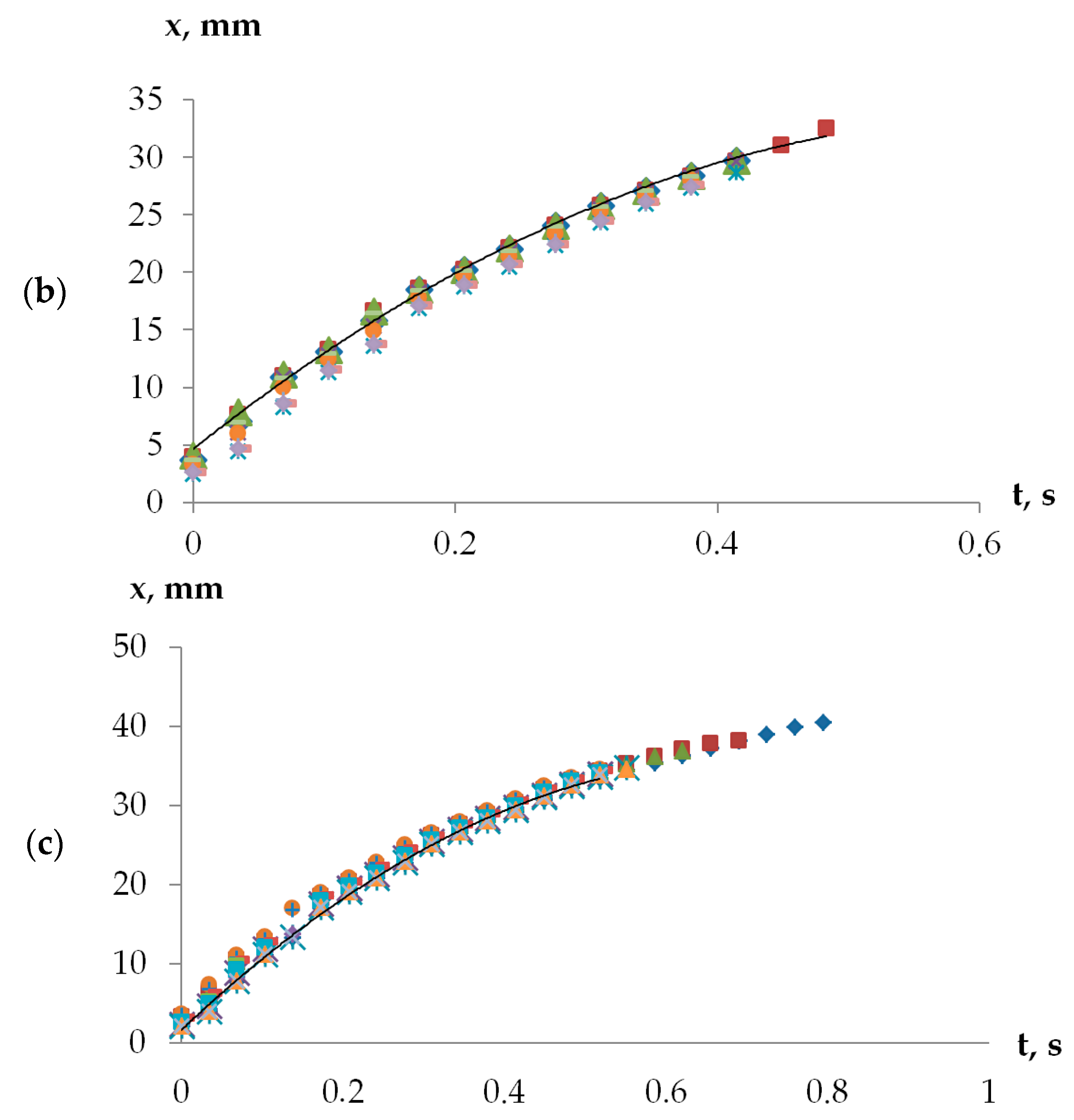
| I, A | 0 | 0.9 | 1.8 |
|---|---|---|---|
| a, mm/s2 | 74.34 | 71.03 | 67.58 |
| v0, mm/s | 87.72 | 90.51 | 96.28 |
| s, mm2 | 14.09 | 12.31 | 11.30 |
Disclaimer/Publisher’s Note: The statements, opinions and data contained in all publications are solely those of the individual author(s) and contributor(s) and not of MDPI and/or the editor(s). MDPI and/or the editor(s) disclaim responsibility for any injury to people or property resulting from any ideas, methods, instructions or products referred to in the content. |
© 2022 by the authors. Licensee MDPI, Basel, Switzerland. This article is an open access article distributed under the terms and conditions of the Creative Commons Attribution (CC BY) license (https://creativecommons.org/licenses/by/4.0/).
Share and Cite
Sokolov, E.; Kaluzhnaya, D.; Shel’deshova, E.; Ryapolov, P. Formation and Behaviour of Active Droplets and Bubbles in a Magnetic Fluid in an Inhomogeneous Magnetic Field. Fluids 2023, 8, 2. https://doi.org/10.3390/fluids8010002
Sokolov E, Kaluzhnaya D, Shel’deshova E, Ryapolov P. Formation and Behaviour of Active Droplets and Bubbles in a Magnetic Fluid in an Inhomogeneous Magnetic Field. Fluids. 2023; 8(1):2. https://doi.org/10.3390/fluids8010002
Chicago/Turabian StyleSokolov, Evgeniy, Dariya Kaluzhnaya, Elena Shel’deshova, and Petr Ryapolov. 2023. "Formation and Behaviour of Active Droplets and Bubbles in a Magnetic Fluid in an Inhomogeneous Magnetic Field" Fluids 8, no. 1: 2. https://doi.org/10.3390/fluids8010002
APA StyleSokolov, E., Kaluzhnaya, D., Shel’deshova, E., & Ryapolov, P. (2023). Formation and Behaviour of Active Droplets and Bubbles in a Magnetic Fluid in an Inhomogeneous Magnetic Field. Fluids, 8(1), 2. https://doi.org/10.3390/fluids8010002