Article

Puncture of a Viscous Liquid Film Due to Droplet Falling

by
Viktor G. Grishaev
1,*,
Ivan K. Bakulin
1,
Alidad Amirfazli
2 and
Iskander S. Akhatov
1
1
Center for Materials Technologies, Skolkovo Institute of Science and Technology, Bolshoy Boulevard 30, bld. 1, Moscow 121205, Russia
2
Department of Mechanical Engineering, York University; Toronto, ON M3J 1P3, Canada
*
Author to whom correspondence should be addressed.
Fluids 2022, 7(6), 196; https://doi.org/10.3390/fluids7060196
Submission received: 14 May 2022 / Accepted: 6 June 2022 / Published: 8 June 2022
(This article belongs to the Special Issue Fluids and Surfaces)

Abstract

:
Droplet impact may rupture a liquid film on a non-wettable surface. The formation of a stable dry spot has only been studied in the inviscid case. Here, we examine the break-up of viscous films, and demonstrate the importance and role of the viscous dissipation in both film and droplet. A new model was therefore proposed to predict the necessary droplet energy to create a dry spot. It also showed that the dissipation contribution in film dominates when the ratio of the thicknesses to drop diameter is larger than 7/4.

1. Introduction

Liquid films cover solid surfaces in many natural and industrial processes. Often films are exposed to falling droplets, for example, during raining, cooling, spraying or lubrication processes. To understand the interaction of droplets with films, many studies focus on drop impact outcomes (splashing, droplet deposition or rebound) or film deformations during these processes (see, e.g., [1,2,3,4,5,6,7,8,9]). Despite many works, less attention is paid to drop impact leading to film rupture, and more specifically the conditions at which a stable hole is formed. Understanding this latter point is important as it can affect the above applications, e.g., in lubrication, leading to areas that are not covered by the viscous film.
The rupture of a liquid film on a solid surface has also been considered in different aspects and conditions. For example, it is found that short- and long-range interfacial forces determine dewetting patterns of thin (<60 nm) liquid polymer films [10]. The motion of dry spots in thicker (1.5–4 mm) films of aqueous glycerol solution is described well by a lubrication model [11]. A dry spot may also appear in a dynamic liquid film forming under droplet impact onto a dry solid surface. In this case, the dry spot formation is determined by impact velocities, surface roughness and the size of defects presenting on solid surface [12,13,14]. Besides dry spot dynamics, it has been revealed that a stable dry spot exists in a liquid film, when its diameter is bigger than a critical value [15]. Although the various aspects of film rupture have been considered, the case due to droplet falling remains less studied.
Up to now, film rupture due to droplet falling has been considered for the cases when a dry spot growth is induced by a surface tension inhomogeneity or impact itself. If a droplet has a miscible liquid with a low surface tension, then its falling creates a local reduction of film surface tension. Such reduction is enough to puncture 1–100 μm thick water films spontaneously due to emerging Marangoni flows [16]. The rupture of thicker films has been considered for aqueous films and droplets. In this case, a stable dry spot forms if the impact dynamics leads to the appearance of a critical size crater [17] or hole [18]. As the impact-induced film rupture is observed at high Reynolds numbers (>>1), the fluid viscosity was neglected in the models developed to date.
Thus, the film rupture under drop impact has been studied only for the inviscid case. However, many applications involve fluids with viscosities considerably higher than water. To understand the contribution of fluid viscosity, we experimentally studied the puncture of viscous films due to a falling drop made of the same fluid. Furthermore, we evaluate droplet energy required to form a stable dry spot.

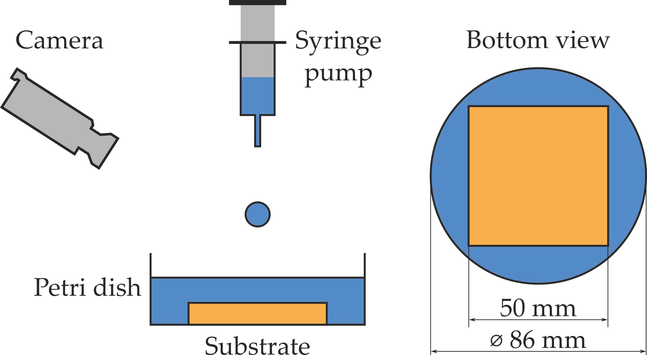
2. Materials and Methods

The film rupture experiments were carried out with aqueous glycerol solutions. We also used the data for distilled water from [17]. The properties of the fluids are presented in Table 1. We choose the specific mass fractions of glycerol to have a suitable range of viscosities. Additionally, the specific fraction of glycerol was selected to be able to identify the threshold of the film rupture (see below).
The test substrate was aluminum (50 mm × 50 mm × 2 mm) covered with a superhydrophobic coating (NeverWet, Rust-Oleum, Vernon Hills, IL, USA). We used the superhydrophobic surface as the film rupture will be the most profoundly observed. The static contact angles of considered fluids on the substrates are given in Table 1.
Our experimental set-up consists of a syringe pump with a test liquid, a Petri dish with the test substrate glued to its floor, which was then covered by the test liquid, and a high-speed camera, as shown in Figure 1; further details can be found in [17]. The syringe pump dispenses the fluid slowly to form a droplet at the needle tip. The detached droplet falls on a liquid film covering the substrate in the Petri dish. The high-speed camera records the collision of the droplet with the film and subsequent formation (or not) of a stable dry spot.
The film thickness is set by forming a thick fluid layer on the substrate at the beginning and then removing the excessive volume. The addition and removal of liquid volumes are done with a digital pipette. The volume of removed liquid is determined using a calibration curve, that was obtained using a wet film thickness gauge (see details in [17]).
The droplet velocity is varied by changing the distance between the needle tip and the Petri dish. The velocity of a falling droplet and its diameter were determined from side view images captured by the high-speed camera. The details of the image processing can be found in [17,19]. The ranges of considered experimental conditions are presented in Table 2.

3. Results

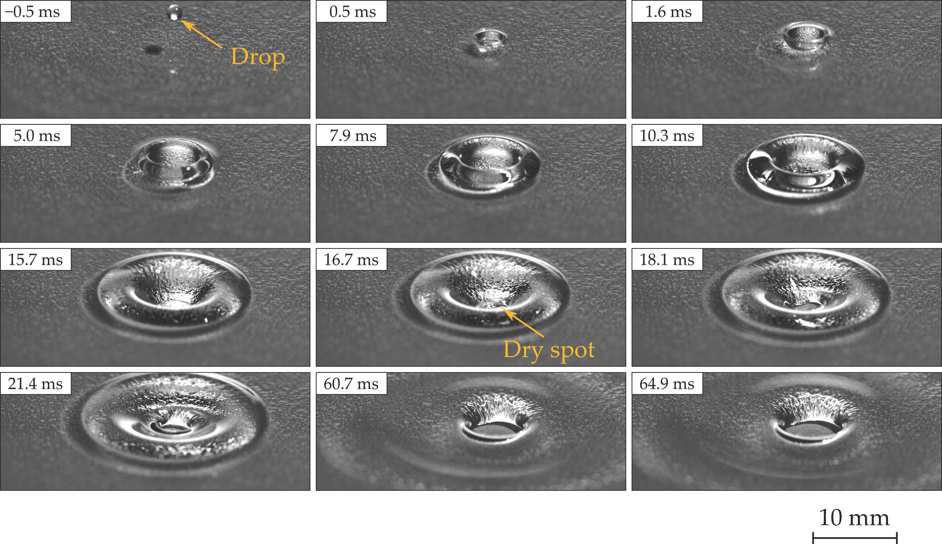
3.1. Experimental Observations

The drop impact leads to the formation of a crater in a liquid film; Figure 2 shows an example of an image sequence. At 16.7 ms, the thin film ruptures at the bottom of the crater, and a dry spot appears. Then, the rim of the crater diverged from the dry spot forming ripples. The left dry spot enlarged to an equilibrium size (it is not shown in the figure). For aqueous glycerol solutions, the rupture of a crater bottom always causes the formation of a stable dry hole at the end of the impact process.
The behavior of the fluid films was studied for different droplet velocities and film thicknesses. For each case, the total energies (kinetic plus surface) of impacting droplets were calculated using measured droplet velocity U , diameter D and fluid properties (density, ρ , and surface tension, γ ), i.e., as ρ π 12 D 3 U 2 + γ π D 2 . The calculated values leading or not to formation of a dry spot are shown in Figure 3. For comparison, we added a plot with data for pure water from [17]. Unlike water films, viscous films are broken up at higher droplet energies. Furthermore, they showed a new case when a dry spot may or may not appear, which depends on whether the thin film at the bottom of the crater ruptures or not (Figure 2). Note, water films rupture of the thin film at the bottom of the crater does not guarantee that a stable dry spot will be observed as the dry spot formed can close due to surface forces [17].

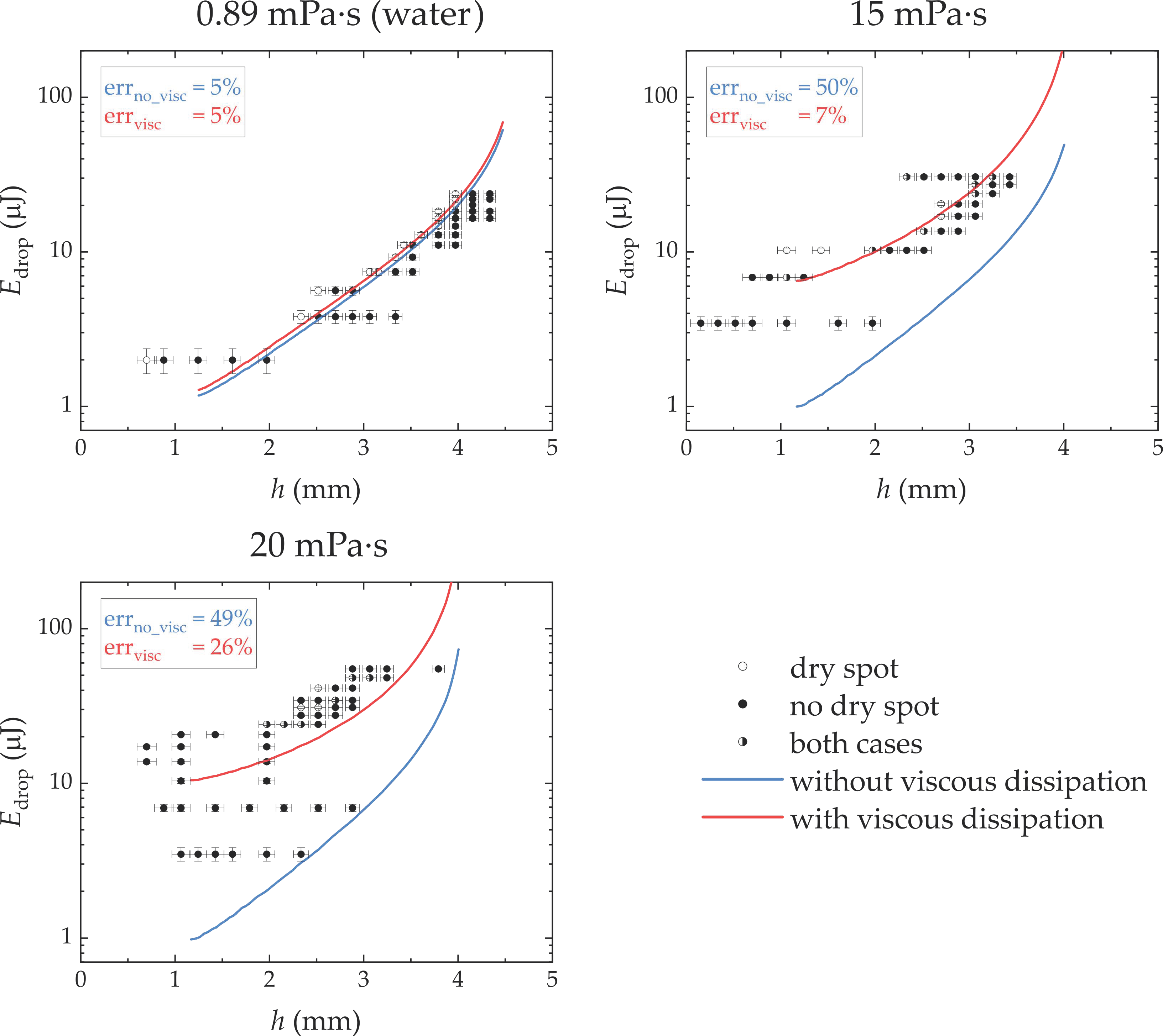
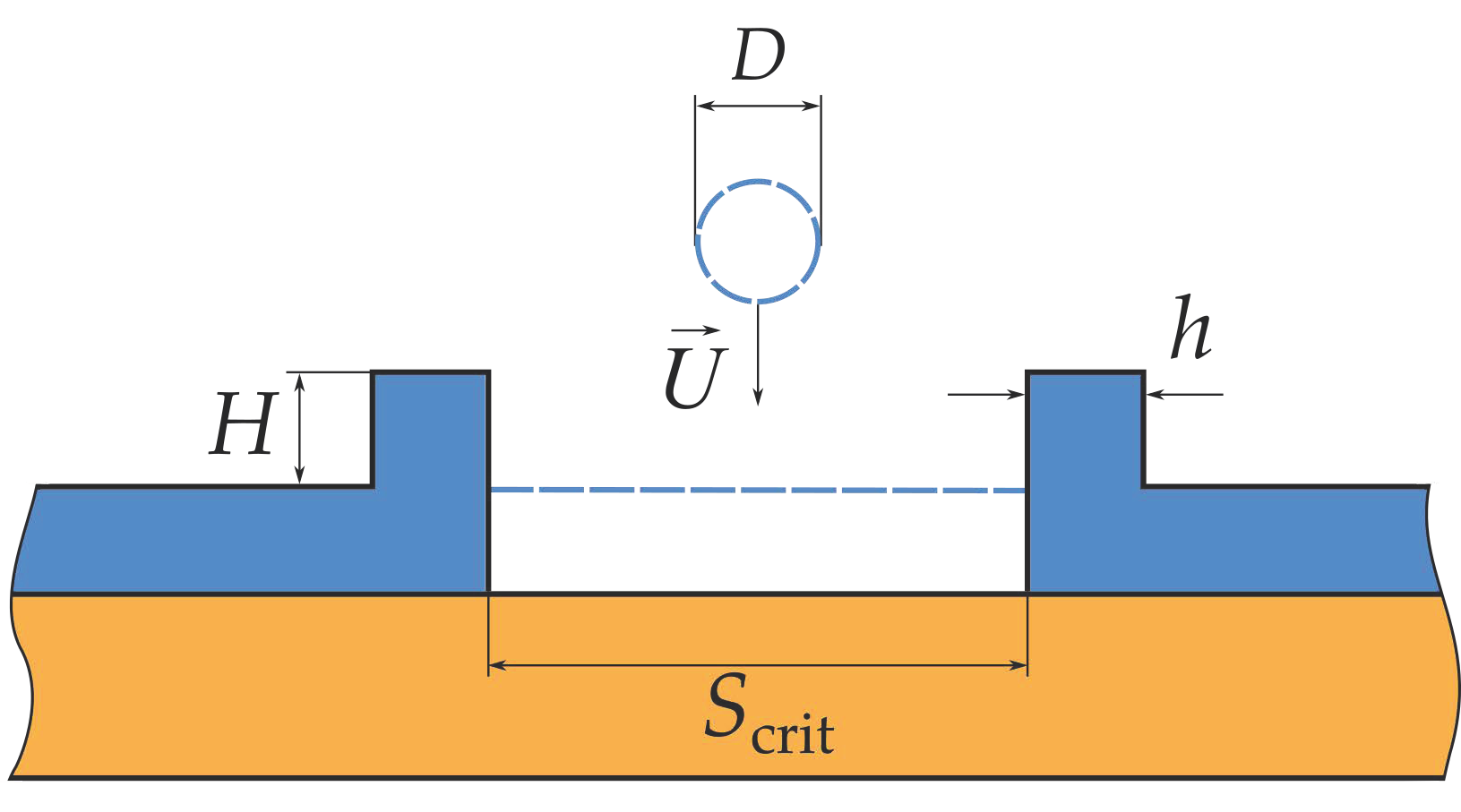
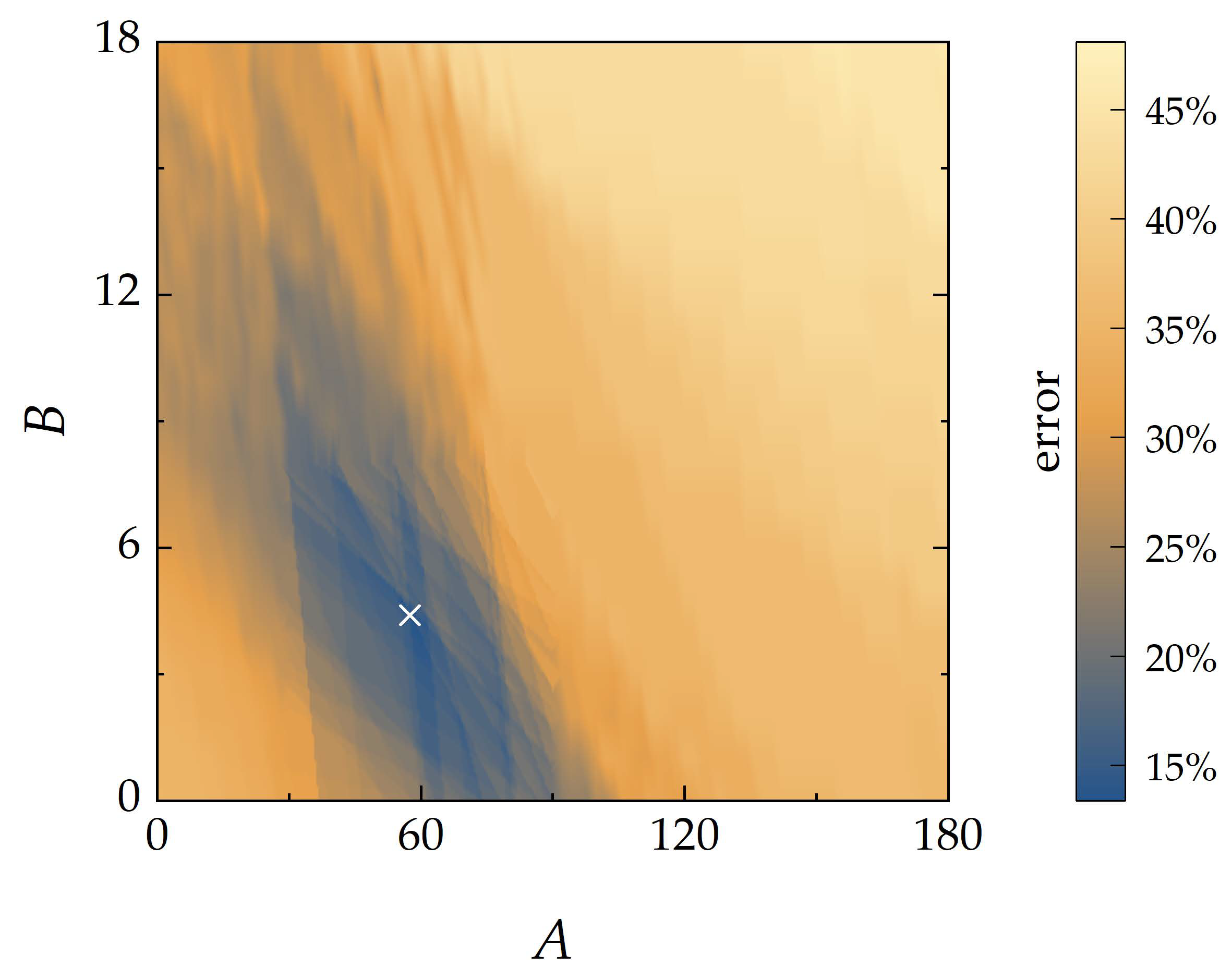
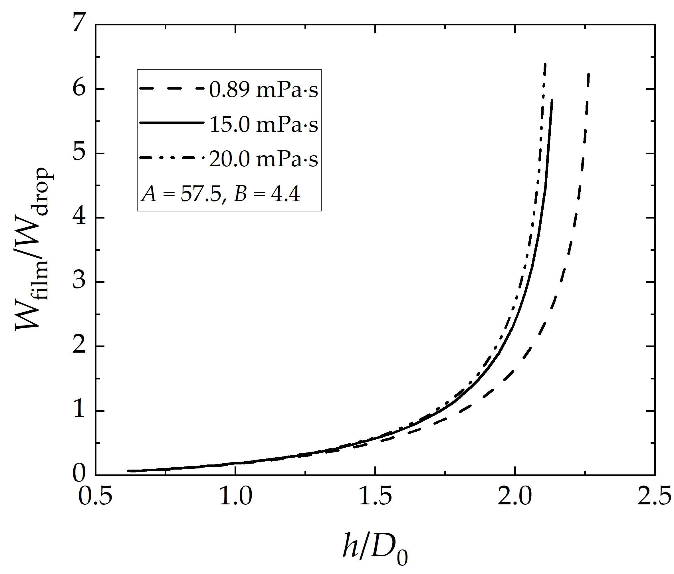
3.2. Evaluation of Required Droplet Energy

To describe the observed phenomena, as a first step, we used the approach proposed in [17] for the inviscid case. The approach in [17] assumes that a stable dry spot appears in a liquid film, if the droplet energy is sufficient to form a cylindrical crater with a critical size of a dry base (Figure 4). The critical area of the dry base, S crit , was determined by calculation of the difference of free energies of the state of the film with and without the dry spot. The curve of the free energy difference versus the area of dry spot showed an energy barrier. If the film overcomes this barrier, then a state with a dry spot becomes favorable.
Therefore, the critical area of the crater base was set to be equal to the area corresponding to the peak of the barrier. The total change of surface and potential energies with the crater formation were calculated using volume conservation and the assumption that the width of the crater rim is equal to film thickness. This type of calculation, however, underestimated the values of droplet energies for aqueous glycerol solutions, i.e., viscous systems (Figure 3).
To improve the model in [17], we considered an energy dissipation by viscous forces. For an incompressible Newtonian fluid, the viscous dissipation of energy is determined by the following integral over time, t , and fluid volume, V :
W = 2 μ t V e i j 2 d V d t
where μ is the dynamic viscosity of the fluid and e i j = 1 2 u i x j + u j x i is the rate-of-strain tensor [23]. Solving of such integral is a complex task. Therefore, in drop impact, the evaluation of the viscous dissipation of energy is often done by using the following approximation:
W ~ μ U c L c 2 Ω c t c
where U c is the order of velocity change over the characteristic distance, L c , for the fluid volume, Ω c , during the time, t c [24,25]. As the viscous dissipation of energy takes place during the droplet and film deformation, it can be written as the following summation with each term to be evaluated separately:
W = W drop + W film
For the deforming droplet, the parameters for the evaluation of the viscous dissipation of energy are:
U c ~ U ;   L c ~ D ; Ω c ~ D 3 ; t c ~ D U
Then, the viscous dissipation of energy in a deforming droplet is proportional to
W drop ~ μ U D 2 D 3 D U ~ μ U D 2
In turn, the viscous dissipation of energy in the film happens due to formation of the crater, i.e., liquid being displaced from the bottom of the crater; as such, the relevant parameters are:
U c ~ U ;   L c ~ h ; Ω c ~ h S crit ; t c ~ h U
which leads to:
W film ~ μ U h 2 h S crit h U ~ μ U S crit
Therefore, the total viscous dissipation of energy can be written as:
W = A μ U D 2 + B μ U S crit
where A and B are non-dimensional constants.
Taking into account the viscous dissipation, the droplet energy for the film puncture is determined as:
E drop = E inviscid + W = E inviscid + A μ U D 2 + B μ U S crit
where the term E inviscid corresponds to the surface and potential energies arising from the critical size of the formed crater as in [17]. The constants A and B can be found by fitting Equation (9) to the experimental data.
The suitable values for constants A and B were found by varying them and searching for the minimum average separation error of Equation (9) in relation to all experimental points. As different numbers of experiments resulted in observing a dry spot or not, the separation error was calculated with the equalization on both classes as:
separation   error = 0.5 N ds N ds all + 0.5 N nds N nds all
where N ds is the number of experimental points for which dry spot was observed, but droplet energy was lower than the value of Equation (9), N nds is the number of experimental points for which dry spot was not observed, but droplet energy was higher than the value of Equation (9); N ds all and N nds all are total number of experimental points with and without dry spot, respectively. The separation errors were averaged for all considered viscosities:
average   separation   error = 1 3 j = 1 3 separation   error j
Considering all test fluids, a minimum average separation error was seen for A = 57.5 and B = 4.4 (Figure 5).
Using the above values for A and B , the plots of Equation (9) are shown by blue solid lines in Figure 3. The plotted curves separate the cases with and without dry spots much better than the model without the viscous dissipation of energy. To compare viscous dissipation in the film and in the drop, we plotted their ratios for all three fluids (see Figure 6).

4. Discussion

The results show that the crater model of [17] underestimates the droplet energy for viscous films. The deviation of the thermodynamic model developed in [17] from experimental observation for the droplet energy needed to create a dry spot on a film increases as the viscosity of the film increases; for example, the underestimation for film viscosity of 20 mPa∙s can be as large as an order of magnitude. Addition of the viscous dissipation term to the model developed in [17] substantially improved the prediction for the droplet energy needed to create a dry spot in a film.
The fitting of the developed model to experimental data allows us to evaluate the contribution of the viscous dissipation in a drop and a film (Figure 6). As the critical area of the crater bottom, S crit , depends on the film thickness, the viscous dissipation in a film increased with increasing of the film thickness. The ratio of film to drop dissipation are not the same for the different viscosities, because of the difference in other fluid properties that influence the critical area. Nevertheless, the results in Figure 6 show that the contribution of viscous dissipation of energy in the film dominates for cases where film thicknesses to droplet diameter ratio are larger than 7/4.
The remaining error of the fitted model is likely due to the assumptions that are made in developing the model. For example, the real shape of the crater deviates from the cylindrical form assumed in the model, see Figure 4 (for model) and Figure 2 (the snapshots at 10.3 ms from experiments). Furthermore, the error may be due to the approximation of viscous dissipation. Another contributing factor can be a new mechanism of the film rupture (see below).
For the viscous fluids, we observed a new case when film rupture may happen or not at the same impact conditions. At such conditions, the falling droplet forms a crater with a thin film at the bottom. When the rim of the crater starts to settle, it not only diverges from an impact point but also starts to backfill the bottom of the crater (cf., snapshots from 10.3 to 16.7 ms in Figure 2). If a thin film at the bottom of the crater does not have sufficient time to break, then the diverging and settling crater rim fills the cavity. However, if the thin film has sufficient time to rupture before thickening, then the dry spot always prevents the filling of the cavity and the crater rim only moves outwards from the impact point with broadening and ripples observed (snapshots from 21.4 to 64.9 ms in Figure 2). Such peculiarity of the film rupture was not mentioned in the previous works [17,18], and it probably should be considered in further modelling.

5. Conclusions

It has been shown that to calculate the external energy needed to break a liquid film over a surface, one needs to consider viscous dissipation of energy, if liquids with a low viscosity, other than water, are used. As such, a new model was developed to allow prediction of the energy needed. Our semi-analytical model correctly predicts the order of magnitude of the needed droplet energy as the external stimuli to create a dry spot in a liquid film. Our experimental results show that droplet energy for the film rupture (the formation of a stable dry spot) increases with viscosity. This is correctly predicted by the new model developed here. Furthermore, using the model developed, we understood that the dissipation occurs in both the droplet and the film, but in non-equal terms. It is shown that the dissipation in films will be dominant for cases where the ratio of the thicknesses to drop diameter is larger than 7/4.

Author Contributions

Conceptualization, V.G.G., I.K.B. and A.A.; methodology, V.G.G., I.K.B. and A.A.; software, I.K.B.; validation, V.G.G. and I.K.B.; formal analysis, I.K.B.; investigation, I.K.B.; resources, I.S.A.; data curation, V.G.G. and I.K.B.; writing—original draft preparation, V.G.G.; writing—review and editing, A.A., I.K.B. and I.S.A.; visualization, I.K.B.; supervision, I.S.A.; project administration, V.G.G.; funding acquisition, V.G.G. All authors have read and agreed to the published version of the manuscript.

Funding

This research was funded by the Russian Science Foundation, grant number 19-79-10272.

Institutional Review Board Statement

Not applicable.

Informed Consent Statement

Not applicable.

Data Availability Statement

The data presented in this study are available on request from the corresponding author.

Acknowledgments

We thank Ivan Borodulin for fabricating the superhydrophobic substrates.

Conflicts of Interest

The authors declare no conflict of interest. The funders had no role in the design of the study; in the collection, analyses, or interpretation of data; in the writing of the manuscript, or in the decision to publish the results.

References

  1. Tropea, C.; Marengo, M. The Impact of Drops on Walls and Films. Multiph. Sci. Technol. 1999, 11, 19–36. [Google Scholar] [CrossRef]
  2. Cossali, G.E.; Brunello, G.; Coghe, A.; Marengo, M. Impact of a Single Drop on a Liquid Film: Experimental Analysis and Comparison With Empirical Models Experimental Set-Up. In Proceedings of the Italian Congress of Thermofluid Dynamics UIT, Ferrera, Italy, 30 June–2 July 1999. [Google Scholar]
  3. Huang, Q.; Zhang, H. A Study of Different Fluid Droplets Impacting on a Liquid Film. Pet. Sci. 2008, 5, 62–66. [Google Scholar] [CrossRef] [Green Version]
  4. van Hinsberg, N.P.; Budakli, M.; Göhler, S.; Berberović, E.; Roisman, I.V.; Gambaryan-Roisman, T.; Tropea, C.; Stephan, P. Dynamics of the Cavity and the Surface Film for Impingements of Single Drops on Liquid Films of Various Thicknesses. J. Colloid Interface Sci. 2010, 350, 336–343. [Google Scholar] [CrossRef] [PubMed]
  5. Josserand, C.; Ray, P.; Zaleski, S. Droplet Impact on a Thin Liquid Film: Anatomy of the Splash. J. Fluid Mech. 2016, 802, 775–805. [Google Scholar] [CrossRef] [Green Version]
  6. Kuhlman, J.M.; Hillen, N.L. Droplet Impact Cavity Film Thickness Measurements versus Time after Drop Impact and Cavity Radius for Thin Static Residual Liquid Layer Thicknesses. Exp. Therm. Fluid Sci. 2016, 77, 246–256. [Google Scholar] [CrossRef]
  7. Chen, B.; Wang, B.; Mao, F.; Wen, J.; Tian, R.; Lu, C. Experimental Study of Droplet Impacting on Inclined Wetted Wall in Corrugated Plate Separator. Ann. Nucl. Energy 2020, 137, 107155. [Google Scholar] [CrossRef]
  8. Ribeiro, D.F.S.; Silva, A.R.R.; Panão, M.R.O. Insights into Single Droplet Impact Models upon Liquid Films Using Alternative Fuels for Aero-Engines. Appl. Sci. 2020, 10, 6698. [Google Scholar] [CrossRef]
  9. Lakshman, S.; Tewes, W.; Harth, K.; Snoeijer, J.H.; Lohse, D. Deformation and Relaxation of Viscous Thin Films under Bouncing Drops. J. Fluid Mech. 2021, 920, A3. [Google Scholar] [CrossRef]
  10. Seemann, R.; Herminghaus, S.; Jacobs, K. Dewetting Patterns and Molecular Forces: A Reconciliation. Phys. Rev. Lett. 2001, 86, 5534–5537. [Google Scholar] [CrossRef]
  11. Bankoff, S.G.; Johnson, M.F.G.; Miksis, M.J.; Schluter, R.A.; Lopez, P.G. Dynamics of a Dry Spot. J. Fluid Mech. 2003, 486, 239–259. [Google Scholar] [CrossRef]
  12. Dhiman, R.; Chandra, S. Rupture of Thin Films Formed during Droplet Impact. Proc. R. Soc. A Math. Phys. Eng. Sci. 2010, 466, 1229–1245. [Google Scholar] [CrossRef]
  13. Biance, A.L.; Pirat, C.; Ybert, C. Drop Fragmentation Due to Hole Formation during Leidenfrost Impact. Phys. Fluids 2011, 23, 022104. [Google Scholar] [CrossRef]
  14. Rashidian, H.; Sellier, M.; Mandin, P. Dynamic Wetting of an Occlusion after Droplet Impact. Int. J. Multiph. Flow 2019, 111, 264–271. [Google Scholar] [CrossRef]
  15. Lv, C.; Eigenbrod, M.; Hardt, S. Stability and Collapse of Holes in Liquid Layers. J. Fluid Mech. 2018, 855, 1130–1155. [Google Scholar] [CrossRef]
  16. Neél, B.; Villermaux, E. The Spontaneous Puncture of Thick Liquid Films. J. Fluid Mech. 2018, 838, 192–221. [Google Scholar] [CrossRef]
  17. Grishaev, V.; Bakulin, I.; Amirfazli, A.; Borodulin, I.; Akhatov, I. Energy of a Drop Required to Break a Liquid Film. Langmuir 2021, 37, 10433–10438. [Google Scholar] [CrossRef]
  18. Ni, Z.; Chu, F.; Li, S.; Luo, J.; Wen, D. Impact-Induced Hole Growth and Liquid Film Dewetting on Superhydrophobic Surfaces. Phys. Fluids 2021, 33, 112113. [Google Scholar] [CrossRef]
  19. Grishaev, V. Impact of Particle-Laden Drops on Substrates with Various Wettability. Ph.D. Thesis, Université Libre de Bruxelles, Bruxelle, Belgium, 2015. [Google Scholar]
  20. Calculate Density and Viscosity of Glycerol/Water Mixtures. Available online: http://www.met.reading.ac.uk/~sws04cdw/viscosity_calc.html (accessed on 15 April 2022).
  21. Cheng, N.-S. Formula for the Viscosity of a Glycerol−Water Mixture. Ind. Eng. Chem. Res. 2008, 47, 3285–3288. [Google Scholar] [CrossRef]
  22. Volk, A.; Kähler, C.J. Density Model for Aqueous Glycerol Solutions. Exp. Fluids 2018, 59, 75. [Google Scholar] [CrossRef] [Green Version]
  23. Acheson, D.J. Elementary Fluid Dynamics. In Oxford Applied Mathematics and Computing Science Series; Oxford University Press: Oxford, UK, 2005; ISBN 0198596790. [Google Scholar]
  24. Chandra, S.; Avedisian, C.T. On the Collision of a Droplet with a Solid Surface. Proc. R. Soc. A Math. Phys. Eng. Sci. 1991, 432, 13–41. [Google Scholar] [CrossRef]
  25. Huang, H.M.; Chen, X.P. Energetic Analysis of Drop’s Maximum Spreading on Solid Surface with Low Impact Speed. Phys. Fluids 2018, 30, 022106. [Google Scholar] [CrossRef]
Figure 1. Schematic of the film rupture experiment.
Fluids 07 00196 g001
Figure 2. Dry spot formation in a liquid film on a superhydrophobic surface after droplet impact for the case of aqueous glycerol solution with viscosity μ = 15 mPa·s. The droplet velocity— U = 3.3 m/s, diameter— D = 1.9 mm, and film thickness— h = 3.1 mm.
Fluids 07 00196 g002
Figure 3. Energies of falling droplets, E drop , leading or not to the formation of stable holes in the liquid films versus their thickness, h . Liquids are water (Data from [17]) and aqueous glycerol solutions. A joint legend outside the plots shows the notation of markers and lines. Legends inside of the plots present the separation errors of the crater model without and with the viscous dissipation of energy (blue and red fonts, respectively).
Fluids 07 00196 g003
Figure 4. Model of the crater formation. The blue dashed lines show a droplet and film before impact.
Fluids 07 00196 g004
Figure 5. Distribution of the average separation error of the crater model with viscous dissipation of energy (Equation (9)) at different constants A and B . The white cross shows the constants (57.5; 4.4) at which the error has minimum value.
Fluids 07 00196 g005
Figure 6. Ratio of viscous dissipation of energy in the film and the drop versus the film thickness. The plotted curves are generated using the values found for parameters A , B (Figure 5).
Fluids 07 00196 g006
Table 1. Properties of experimental fluids (water and aqueous glycerol solutions) at 25 °C.
Glycerol, % Wt.Viscosity 1, mPa·sDensity 1, kg·m−3Surface Tension, mN·m−1Static Contact Angle on Test Substrates, °
00.89 ± 0.021 ± 0.000272.0 ± 0.8169 ± 2
68 ± 0.515 ± 0.91.17 ± 0.00266.4 ± 0.9167 ± 2
71 ± 0.520 ± 1.41.18 ± 0.00265.1 ± 0.8166 ± 2
1 Values were taken from [20,21,22].
Table 2. Conditions of the film rupture experiments. Weber number, We, and Reynolds number, Re, were calculated by using film thickness as a characteristic length.
Glycerol, % Wt.Droplet Diameter, mmDroplet Velocity, m·s−1Film Thickness, mmWeRe
02.0 ± 0.10.7–3.30.7–4.35–657566–16,093
68 ± 0.51.9 ± 0.11.1–3.80.2–3.44–87014–1013
71 ± 0.51.9 ± 0.11.2–5.10.7–3.825–178772–1137
Publisher’s Note: MDPI stays neutral with regard to jurisdictional claims in published maps and institutional affiliations.

