Abstract
Korto’s multidimensional method for vibro-acoustical diagnostics and monitoring of turbine cavitation is based on a high number of spatially distributed sensors and the signal and data processing that systematically utilises three data dimensions: spatial, temporal, and operational. The method delivers unbiased data on cavitation intensity and rich diagnostical data on cavitation mechanisms. It is applicable on Kaplan, Francis, bulb, and reversible pump turbines, as well as pumps. In this paper, the theory of the method is introduced, and its application is illustrated on a prototype and three models of a Kaplan turbine. In the considered case, two distinct cavitation mechanisms responsible for the two erosion patches found in an overhaul are vibro-acoustically identified, quantified, and analysed. The cavitation quality of the models is compared. Cavitation as a source of vibration is discussed.
1. Introduction
A direct check of cavitation erosion in a hydro turbine made during an overhaul specifies the total accumulated erosion. More data, including the operational-dependence of erosion and the role of turbine parts in cavitation, are needed to optimise operation for minimal cavitation erosion or to identify, on a prototype, the causes of cavitation. A common method to acquire such data is by means of vibro-acoustical tools for the diagnostics and monitoring of cavitation.
The research and development of these tools have a long history. A century ago, the basics of cavitation acoustics were formulated [1]. Half a century later, with greatly advanced insight into cavitation dynamics, cavitation acoustics, and mechanisms of the damage caused by cavitation (cf. [2]), the first engineering steps were made in the vibro-acoustical assessment of cavitation in hydraulic machinery [3,4]. A further two decades were needed for specific tools for hydro turbines to be conceived and developed [5,6,7]. Since then, broad research on these tools has been conducted; many papers have been published on the vibro-acoustical assessment of cavitation in hydro turbines, reversible pump turbines, pumps, and on special experimental gadgets. This research has incorporated the optimisation of the locations of vibro-acoustical sensors on the machinery [8,9,10,11,12,13,14,15,16,17,18,19,20,21,22,23,24,25,26,27,28], the optimisation of sensor types [8,9,10,13,15,16,17,18,19,23,25,26,27,28] the development of suitable data processing methods, and clarification of the relation between vibro-acoustical quantities and cavitation intensity [8,9,10,11,12,13,14,15,16,17,18,19,20,21,22,23,24,25,26,27,28]. The crucial question here has been whether one can vibro-acoustically distinguish between erosive and non-erosive cavitation and quantify the cavitation erosivity. The early assumption that the non-stationary nature of turbine cavitation is the cause of erosion, and that a quantifier of the cavitation non-stationarity may be used as a measure of its erosivity [6], did not withstand even an ad-hoc check [8]. The topic has been dealt with ever since. A solution is still sought in the cavitation non-stationarity caused by the rotor-stator interaction [27], and along an independent physical line [28]. Although great progress in all aspects of cavitation in hydraulic machinery has been made [29], the practical task of monitoring cavitation is still undergoing intense research and development.
Typically, in monitoring systems described in published reports, a rather limited number of sensors is used. This can result in highly biased cavitation-intensity estimates and lead to wrong conclusions [15,22]. Furthermore, the acquired signals are commonly transformed into quantifiers which – either by their definition or due to simple averaging over time – suppress traces of individual cavitation processes in the cavitation estimates, where these processes are caused by rotor-stator interaction. These quantifiers include the mean spectra of the signals and their envelopes, the root-mean-square values of a signal component or of an envelope spectrum line, the rate of passage of cavitation peaks through an amplitude limit, etc. By most of such signal and data processing, valuable diagnostic information carried by the acquired signals remains unused.
2. The Multidimensional Approach
The approach developed at Korto Cavitation Services [10,12,14,15,22] deviates from this practice and introduces a new paradigm in the methodology of diagnostics and mo-nitoring of turbine cavitation:
- It adds a spatial dimension in the description of the cavitation processes by using many spatially distributed sensors—typically, on all guide-vane trunnions or levers, and on the turbine shaft. This makes the cavitation-intensity estimates unbiased.
- It also adds a time dimension to the description by following variations of cavitation within a revolution, thus assessing and interpreting data dependence on the instantaneous angular position of the runner.
- By checking all the individual spatial and temporal samples at all relevant operation points, it deals with a full set of individual spatial/temporal/operational resolution cells of the quantifiers of the cavitation processes.
- It does not transform the acquired signals into spectra or other globalising formats in which data on individual cavitation processes are smoothed or in which partly or fully disappear. Instead, it preserves and displays full individual data on the cavitation mechanisms generated by the rotor-stator interaction in their natural form. To do so, sufficiently broad-band and fast sensors (acoustic emission sensors or fast accelerometers) are used to pick up all or most components of cavitation-generated noise and to assess them correctly, where the signal and data processing is started by squaring the outputs of (linear) vibro-acoustical sensors; this makes the quantities stemming from independent cavitation mechanisms additive. Using these squares as estimates of the random instantaneous local cavitation intensity, it calculates – synchronised with runner rotation – averages of the squares over revolutions, and delivers estimates of the deterministic description of the cavitation intensity specific to each spatial/temporal/operational cell. This approaches the maximum of the interpretable data on cavitation that can be achieved vibro-acoustically.
Such a multidimensional analysis makes it possible to distinguish between different cavitation mechanisms, to specify the role of both stationary and rotating turbine parts in the cavitation processes, and thus, in a good case, to point to the cause of cavitation. The method does not distinguish between erosive and non-erosive cavitation but is useful in this respect through the recognition of cavitation mechanisms.
The method was developed, tested, and used on Francis, Kaplan, and bulb turbines; it is also applicable on reversible pump-turbines and pumps.
In this paper, the theory of the multidimensional method is introduced, and its application is illustrated on an example of a Kaplan turbine, on its prototype and three models. This illustration was also presented at the Hydro 2022 Conference in Strasbourg, France.
3. Tested Case
Andritz Hydro observed unexpected cavitation erosion on the runner of a 22 MW Kaplan turbine in a run-of-river plant.
As part of the root cause analysis, a vibro-acoustical diagnostic test of cavitation was performed on:
- the prototype; and on three turbine models both in accordance with the common procedure (visual detection of cavitation and sigma-break curves) and vibro-acoustically:
- the model of the existing turbine, tested on the prototype;
- the model with an improved runner;
- the model with both the runner and the guide vanes improved.
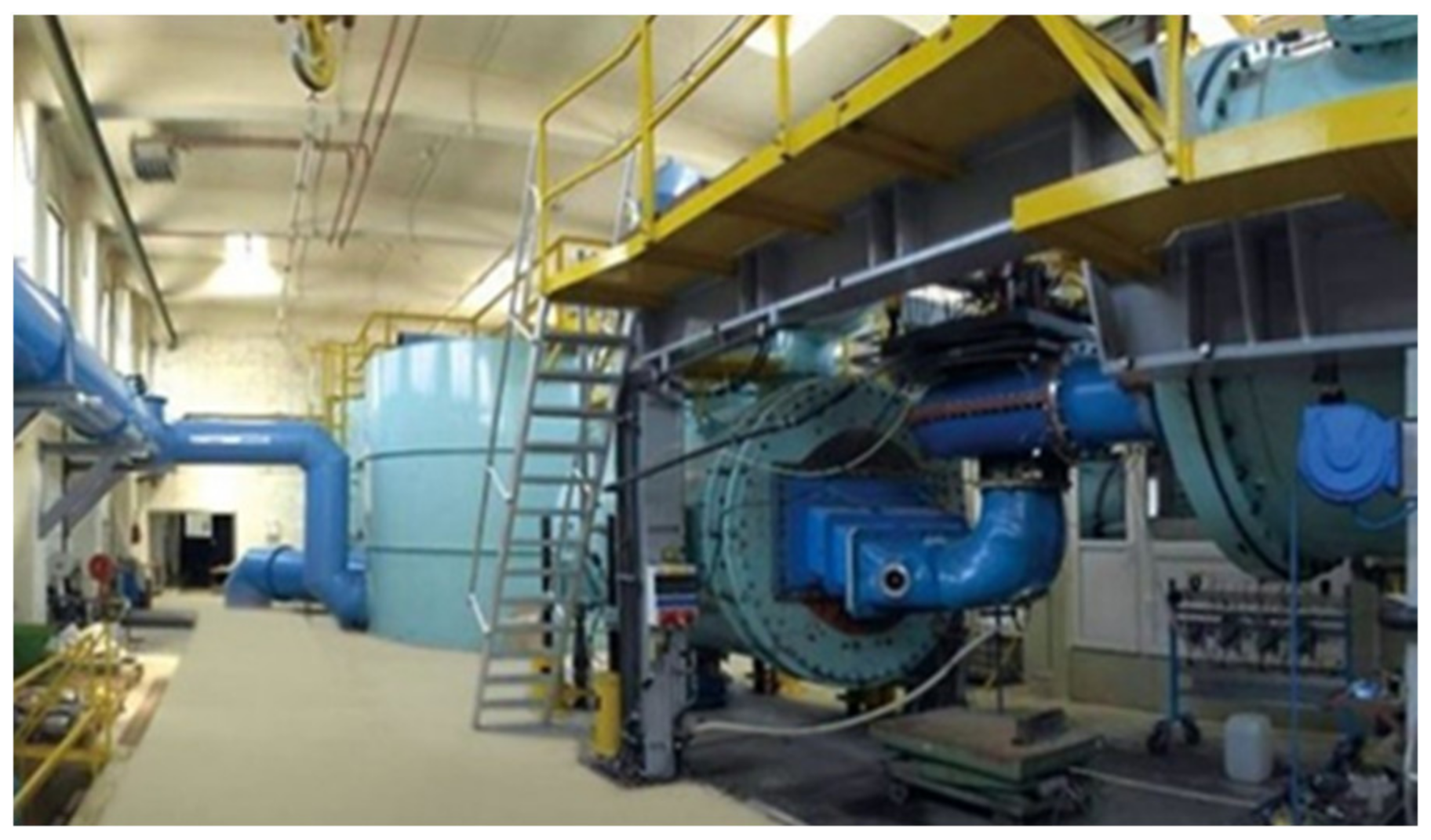
The model tests were performed on one of the test rigs in the Andritz Hydro Labo-ratory in Linz (Figure 1).
Korto was engaged to perform the vibro-acoustical diagnostic test on the prototype; introduce the vibro-acoustical methods in the model tests in the Andritz Hydraulic Laboratory; deliver a comparative vibro-acoustical assessment of the three models.
The multidimensional method, briefly described above, was applied. In this paper, only the vibro-acoustical results are dealt with. Other aspects of Andritz Hydro’s actions in this project are not considered here.
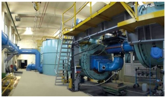
Figure 1.
One of the five model-test rigs in the Andritz Hydro Laboratory in Linz, Austria.
Figure 1.
One of the five model-test rigs in the Andritz Hydro Laboratory in Linz, Austria.
4. Measurement Method
On the turbine with the semi-spiral, two piers, 11+1 stay vanes, 24 guide vanes, and 4 runner blades, fast broadband vibro-acoustical sensors were installed on the turbine shaft and on the trunnions of all the guide vanes, both on the prototype and the models (Figure 2). On both scales, a main processor was used to acquire and pre-process the signals from
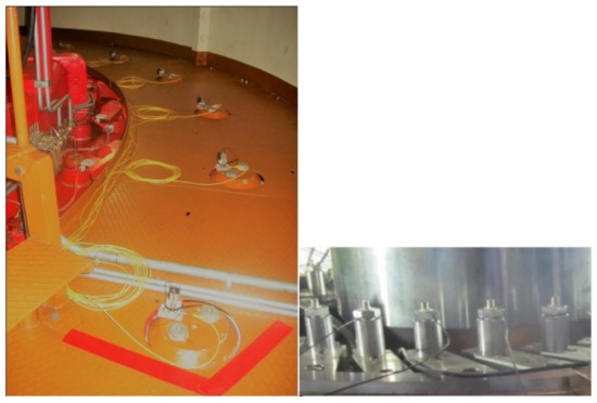
Figure 2.
Vibro-acoustical sensors on the guide-vane trunnions.
Figure 2.
Vibro-acoustical sensors on the guide-vane trunnions.
24 sensors on the guide vanes; for the sensor on the turbine shaft, an additional rotating processor was used.
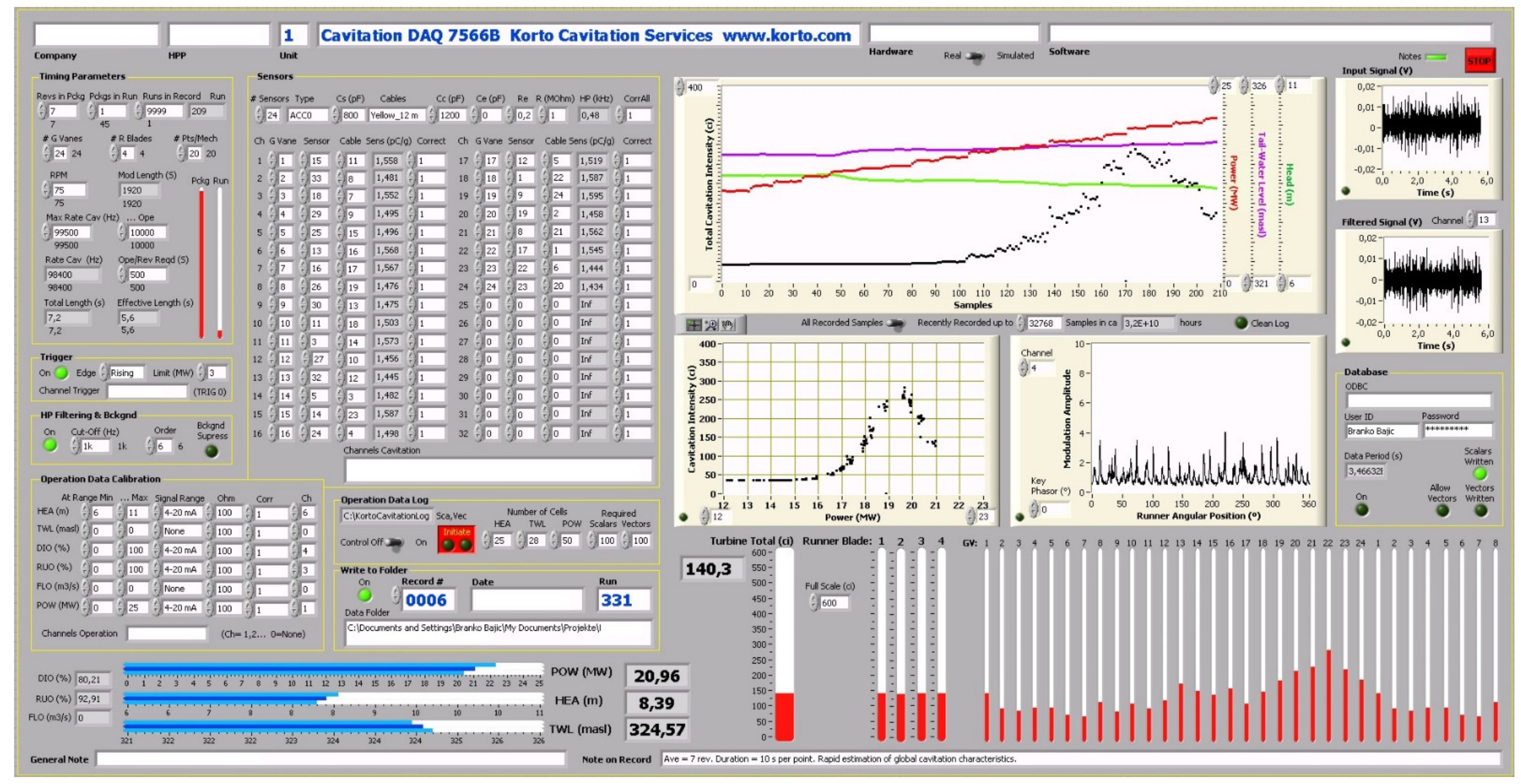
Figure 3 shows the front panel of the main processor.
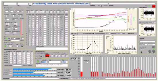
Figure 3.
Front panel of the multidimensional data acquisition processor. The simplest description of cavitation comes out online after half an hour of measurement on the prototype. More complicated descriptions require days or weeks of recorded data analysis by a trained user.
4.1. Data Acquisition
A selected series of stable turbine operation points, denoted here symbolically by , is tested. A dense set of points with cavitation and some points with a non-cavitation background is included in . At each operation point, synchronously with the runner rotation, after suitable high pass filtering against the background,
- the outputs of the sensors on the guide vanes, x(,Θ,Φ,n), and
- the output of the sensor on the turbine shaft, y(,Φ,n), are read (the power for electronics rotating on the shaft is supplied by means of an inductive transmitter for permanent monitoring, or by a battery for short-term tests).
This is conducted:
- in N (not necessarily subsequent) revolutions, n = 1, 2,…, N; in each revolution,
- in a series of a sufficiently high number M of equidistant circumferential angular positions of the runner, Φ, which cover one full revolution (temporal coordinate), and, concerning x(·),
- in V equidistant circumferential angular positions Θ corresponding to all V guide vanes equipped with the sensors (spatial coordinate).
While Φ increases in the direction of runner rotation, any direction for Θ may be used.
With <·>n denoting averaging over revolutions, the quantities
I(,Θ,Φ) = <x(,Θ,Φ,n)2>n–Bx(,Θ)
- spatial and temporal dependence of cavitation intensity assessed by the sensors on the guide vanes at the operation point , and
J(,Φ) = <y(,Φ,n)2>n–By()
- temporal dependence of cavitation intensity assessed by the sensor on the turbine shaft at the operation point ,
are taken for the first estimates of the cavitation intensity; each of them delivers one non-negative real number for each value of , Θ, and Φ. The quantities Bx(,Θ), defined for all Θ values corresponding to the sensors’ locations on the guide vanes, and By() for the sensor on the turbine shaft, denote the estimates of the non-cavitation background components of the cavitation intensity, all of these for the operation point .
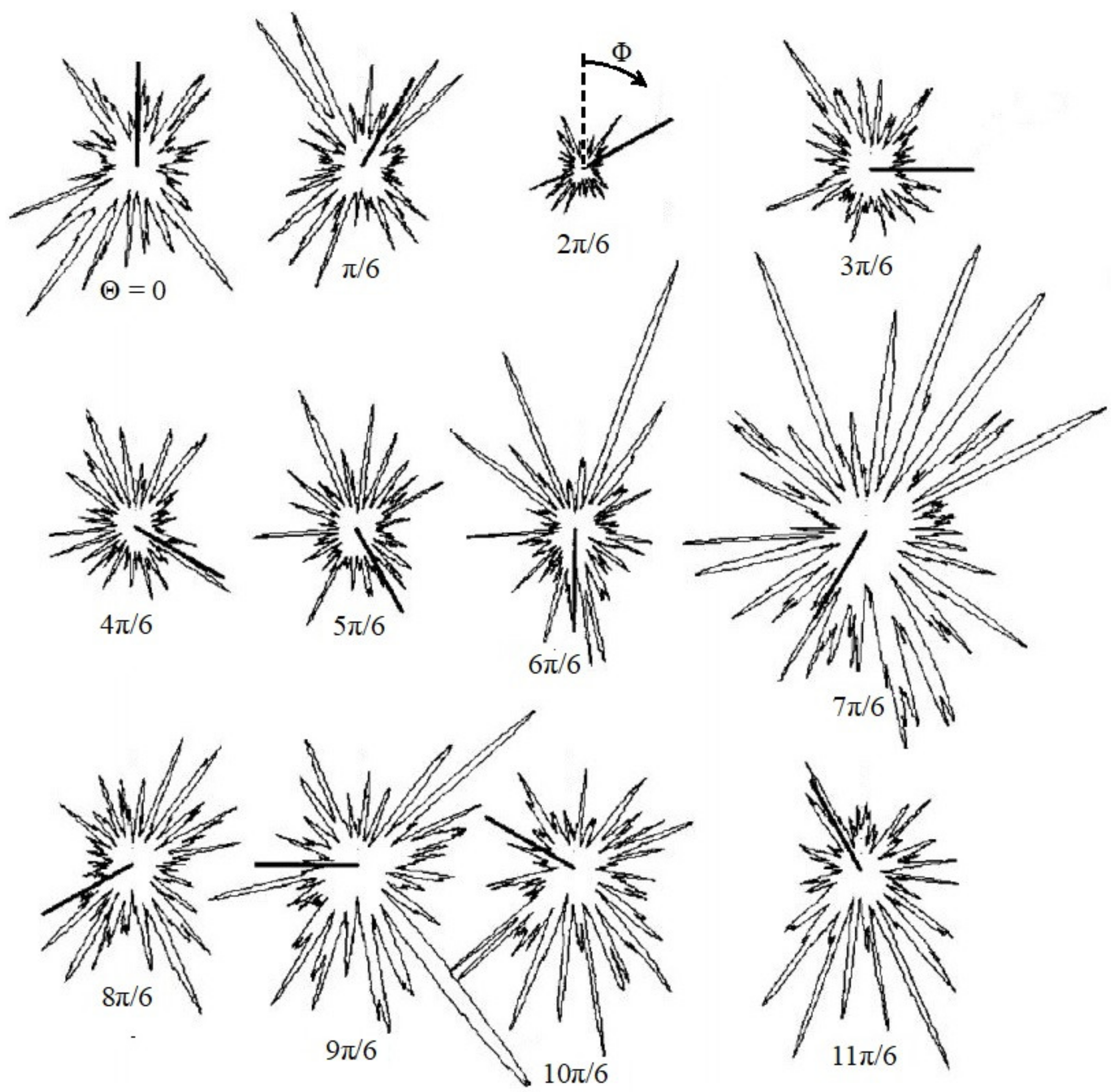
With measurements accomplished at a stable operation point, in which cavitation possibly varies from one to another revolution but may be looked at as a stationary stochastic process that is sampled by the linearly reacting sensors, the results I(,Θ,Φ) (Figure 4) and J(,Φ) deliver estimates of the deterministically given mean square of such a process. As a basic input data format in the multidimensional method, these functions are saved for further analysis for all available values of , Θ, and Φ.
Introductory high pass filtering can eliminate most machinery noise from x(,Θ,Φ,n) and y(,Φ,n) without remarkably disturbing the cavitation contributions in them. However, the flow-noise spectra and those of cavitation substantially overlap, and no simple filtering can help with respect to such high-frequency broad-band disturbances. Since the flow noise typically has a pronounced operation dependence, it is desirable to have the background components of the intensity estimates, Bx(,Θ) and By(), well-defined over the entire band of tested. It is easy to have these for non-cavitation . For incipient and weak cavitation, it is possible to estimate the background in <x(,Θ,Φ,n)2>n and <y(,Φ,n)2>n in the intervals of Φ between cavitation pulses caused by the rotor-stator interaction. The extrapolation of such trends found in can be used for developed cavitation.
As a first guess, more easily obtainable but less reliable background estimates Bx(b,Θ) and By(b), specified for a fixed, safely non-cavitation operation point b, may be used. Further, instead of different values for each Θ, Bx(,Θ) or Bx(b,Θ), equal values for all sensors on the guide vanes, Bx() or Bx(b), may be used.
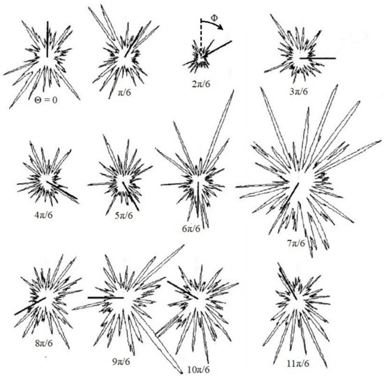
Figure 4.
An illustration of I(,Θ,Φ) recorded at a certain operation point of a Kaplan turbine with 24 guide vanes in which every second vane was equipped with a sensor. The peaks stem from various instances of the rotor-stator interaction. (Reprinted with permission from Ref. [15]. Copyright 2022 Taylor & Francis).
4.2. Parameters Setting
The remaining relative random root-mean-square fluctuations of these cavitation-intensity estimates are approximately equal to N−1/2. Since the measurement at one -point lasts for N revolutions (if processed subsequently), the choice of N must be a compromise between accuracy and the measurement duration. For the prototype, suitable values for N are between 300 and 1000. For model tests which are much faster, even higher values are acceptable.
In the turbine with V guide vanes and B runner blades, VB pronounced traces of the rotor-stator interaction are expected, viewed circumferentially. If each of the resulting angular patterns of cavitation intensity is described by K subsequent circumferential points, the number of samples per revolution, M, equal to or higher than KVB should be set. With K of the order of 20, and V = 24 and B = 4, a good value for M would be 2000.
The signal sampling described above does not need to satisfy the common requirement for the sampling rate of at least twice the highest frequency contained in the signal. Due to the random character of the cavitation pulses, in time arrival, width, and amplitude, a kind of dithering is introduced through averaging over revolutions, that makes the under-sampled signal waveform correct. Still, a sampling rate higher or even much higher than M samples per revolution is welcome; this supports efficiency of averaging. The outputs of the sensors, x(,Θ,Φ,n) and y(,Φ,n), should be sampled at such a selected full rate, and decimated to M samples per revolution after averaging of the squares according to (1) and (2). Decimation with averaging should be used to improve the stability of the cavitation intensity estimates and to allow lower values of N to be set. The basic requirement for the bandwidth of the sensors and signal processing units is to pass the highest frequencies contained in the signals: the bandwidth is essential, the sampling rate is not.
4.3. Additivity of Mechanisms
Erosion pits caused on the runner by cavitation generate structure-borne sound that propagates from the pit location through the turbine shaft to the sensor on it. However, the big runner blade surface also acts as a receiver for hydroacoustic waves generated in water by the same cavitation and by other segments of the cavitation flow, also non-erosive ones. Thus, the received signals are a mixture of interesting and uninteresting components. The situation with the sensors on the guide vanes is even worse. Here, the entire structure-borne sound stems from the hydroacoustic waves.
The turbine structures through which the structure-borne sound waves propagate introduce a kind of directivity even if the sensors themselves are nondirective. Although the sensors emphasise noise components stemming from cavitation in their vicinity, the signals they receive at a certain moment can be generated by cavitation in various locations. In the measurement procedure described above, there is a tool which makes the first step towards distinguishing between such components: as shown in what follows, it makes these components additive.
Common sensors react to the excitation in a linear manner. The same holds for the transmission channel since the structure-borne sound caused in them by cavitation is well below the limit of material nonlinearity. Thus, if there are two components in the excitation, i.e., the components corresponding to two cavitation mechanisms, the sensor reacts to the sum,
and the intensity (1) consists of the intensities corresponding to the components, (a) and (b),
and a mixed term:
x(,Θ,Φ,n) = xa(,Θ,Φ,n)+xb(,Θ,Φ,n),
Ia(,Θ,Φ) = <xa(,Θ,Φ,n)2>n, and Ib(,Θ,Φ) = <xb(,Θ,Φ,n)2>n,
I(,Θ,Φ) = Ia(,Θ,Φ) + Ib(,Θ,Φ) + Iab(,Θ,Φ),
Iab(,Θ,Φ) = 2<xa(,Θ,Φ,n) xb(,Θ,Φ,n)>.
The qualitatively identical model describes the case with more than two components, as well as the case of the sensor on the turbine shaft. Furthermore, if significant background components are present in the signals, there would be, in (3), additive mean-square terms of such components from (a) and (b) and the mixed term stemming from these. By subtracting the background in (1) and (2), these additions disappear.
For the uncorrelated cavitation components, Iab(,Θ,Φ) ≡ 0, the intensity of cavitation equals the sum of the intensities of the components. There are two causes of such a lack of correlation:
- In almost all cavitation cases, and especially in the erosive ones, signal samples taken at the same values of , Θ, and Φ but in different revolutions are independent and thus uncorrelated:<x(,Θ,Φ,n1) x(,Θ,Φ,n2)> ≡ 0, <y(,Φ,n1) y(,Φ,n2)> ≡ 0, for n1 ≠ n2.
- Even if coming at the same moment, within the same revolution, the cavitation components that are developed in different VB patterns of rotor-stator interaction are independent and thus uncorrelated. Indeed, since stemming from independent inflow wakes, they have an independent fine structure of cavitation pulses.
This randomisation of the measurement results is emphasised through the fine structure of the high-frequency spectral components, which is guaranteed by the introductory high-pass filtering. The well-chosen limiting frequency of this anti-background filtering is typically three orders of magnitude higher than the revolution frequency. This makes the <·>n-averaging effective in removing the uncorrelated signal components.
4.4. Further Data Formats
The basic cavitation-intensity data, I(,Θ,Φ) and J(,Φ) of (1) and (2), can usefully be reduced in various ways:
which shows, at the operation point , spatial dependence of the mean cavitation intensity;
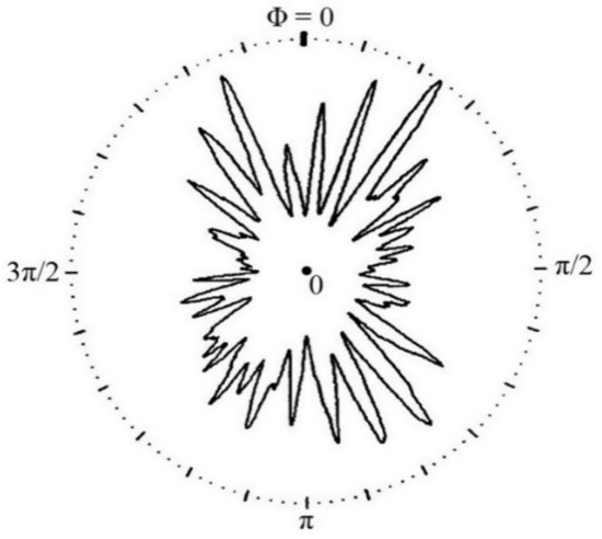
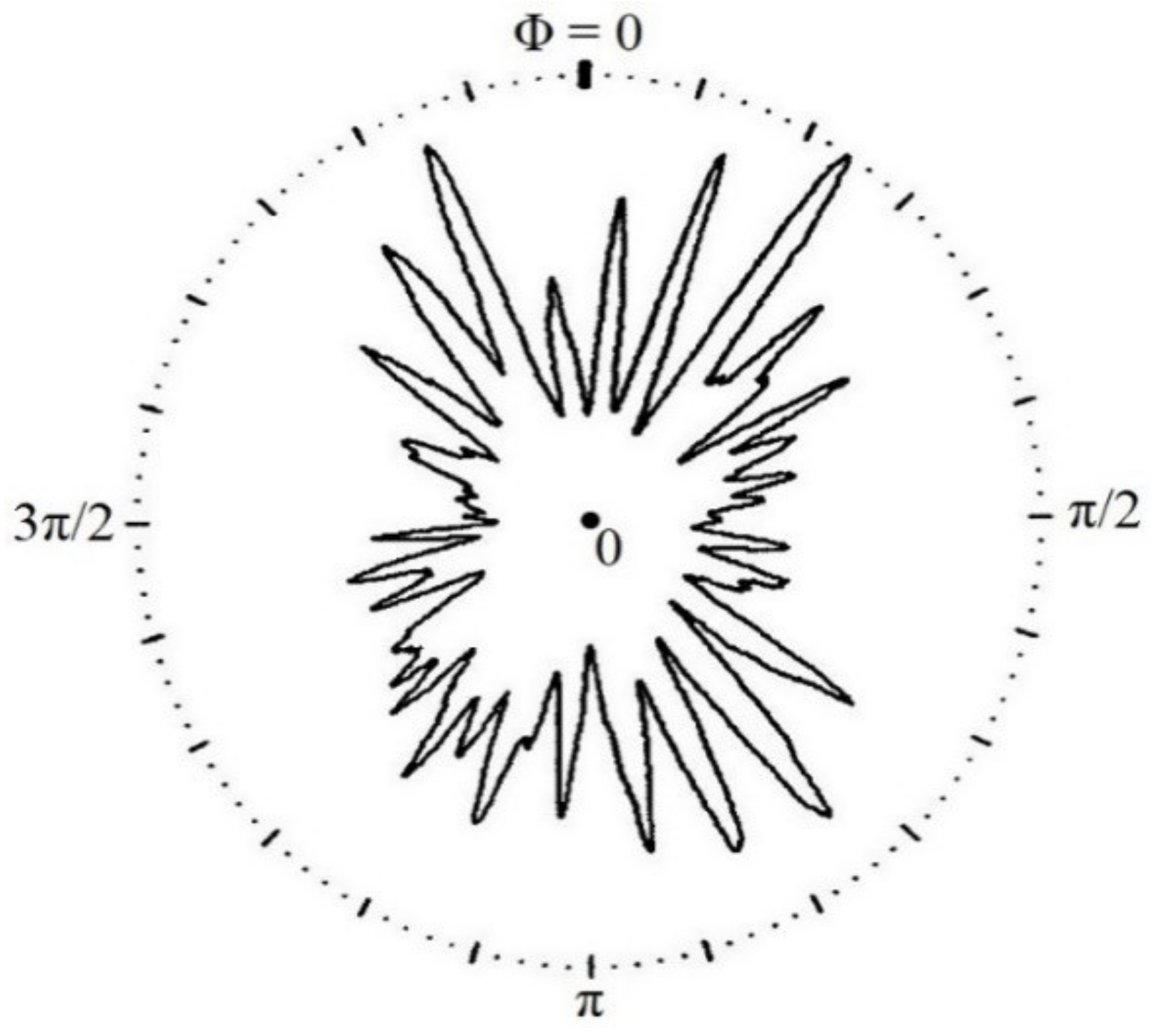
which shows temporal dependence of the spatially mean cavitation intensity (Figure 5);
which shows spatial and temporal dependence of cavitation intensity of the cavitation rotating with the runner; this definition depends on the manner of measuring Φ and Θ;
 which shows temporal dependence of the rotating cavitation mechanism; while (5) focuses on the stationary mechanisms, this illustrates a synthetic sensor focused on the rotating mechanisms;
which shows mean global cavitation intensity assessed by the sensors on the guide vanes;
which shows mean global cavitation intensity assessed by the sensor on the turbine shaft,
Is(,Θ) = <I(,Θ,Φ)>Φ
It(,Φ) = <I(,Θ,Φ)>Θ
Ir(,Θ,Φ) = I(,Θ,Φ-Θ) or I(,Θ,Φ+Θ)

Figure 5.
It(,Φ) derived from the data in Figure 4 presents the use of spatially distributed sensors to form a synthetic sensor focused on stationary cavitation mechanisms; (7) is an analogue focused on rotating mechanisms. (Reprinted with permission from Ref. [15]. Copyright 2022 Taylor & Francis.)

Itr(,Φ) = <Ir(,Θ,Φ)>Θ
I() = <Is(,Θ)>Θ = <It(,Φ)>Φ = <<I(,Θ,Φ)>Θ>Φ = <<I(,Θ,Φ)>Φ>Θ
J() = <J(,Φ)>Φ
where mean signifies averaged over time, i.e., over Φ, and global signifies averaged over space, i.e., over Θ, thus incorporating intensities of all segments of cavitating flow around the runner.
Here, <·>Φ and <·>Θ denote averaging over the interval [0,2π) of Φ and Θ, respectively.
If removing the background disturbances in (1) and (2) is fully successful, the functions (4)–(9) will be free of them. If not, an additional correction is necessary here. A typical example concerns (8) and (9): I() and J() should be replaced by I()-Bx(b) and J()-By(b).
Within the margin of random errors which remain after averaging over n in (1) and (2), all these functions can be considered periodic in both Φ and Θ with a period 2π; thus, Φ ± Θ in (6) may be reduced to the interval [0,2π). In a visual presentation of a function of Φ and/or Θ, it is useful to display the function over two or three periods of these variables. This makes it easier to recognise the particularities of the cavitation process. Such visual analysis, which counts on the trends of the segments of the groups of VB patterns of cavitation intensity rather than on anything about a single pattern, and looks at such segments over various operation bands, is the basic tool of the multidimensional analysis. To a certain degree, this can be automatised; however, a simple direct visual check of the graphs is always a good first step of the analysis.
Due to differences in structure-borne and hydroacoustic/structure-borne sound transmission, effective sensitivities of the channel on the turbine shaft and those on the guide vanes are different. To make the results comparable, an adjustment of the turbine-shaft channel is necessary. This is performed by comparing I() and J() at a suitable operation point o,
and using cJ() and cJ(,Φ) instead of J() and J(,Φ), respectively. The point o is selected to make I() and cJ() coincide or lie close to each other within a suitably selected -interval.
c = I(o)/J(o),
4.5. Quantification of Cavitation Mechanisms
By analysing I(,Θ,Φ) of (1) and Ir(,Θ,Φ) of (6), as well as cJ(,Φ), cJ(), and the other functions of (4)–(9), one can, in many cases, recognise components that stem from different cavitation mechanisms – either different types of cavitation or the same type of cavitation in separated parts of the volume around the runner. All such components are independent and are thus additive. One thus has for (8):
where Im() describes the m-th cavitation mechanism discovered in I(), and Σm denotes the sum over all the mechanisms. The same logic holds true for the other formats of the cavitation-intensity functions, those related to the turbine shaft as well.
As an illustration of the analysis of the trend of VB patterns, here is an example of distinguishing between:
- the cavitation that is basically caused by the particularity of the runner-blade profile, and rotates with the runner blade and seems to be stationary when described in a rotating space, and
- the cavitation that is basically caused by the exceptionally strong wake behind a body upstream of the runner, which then seems to be stationary and is best described in a stationary space.
In I(,Θ,Φ), the stationary mechanisms are presented as a group of patterns along an interval of Θ or the entire period of Θ, but at the constant value of Φ; in Ir(,Θ,Φ), the rotating mechanisms have such a form. In I(,Θ,Φ), the rotating mechanisms appear in a graph as an inclined group of patterns following the rule Φ = Θ ± constant (the sign depending on the definition of Θ), while the stationary mechanisms appear inclined in Ir(,Θ,Φ).
If the respective bands of Θ-values in which the stationary and the rotating mechanisms occur or dominate do not overlap, these mechanisms can be usefully quantified by their total intensities for the given and Φ:
Here, denotes the summation over Θ-values Θv corresponding to the guide vanes v behind which the stationary mechanism occurs (or dominates) in (11), and over Θ-values Θv corresponding to the guide vanes v behind which the rotating mechanism occurs (or dominates) in (12). The mean intensities of the two mechanisms follow:
To compensate for possible inaccuracies in the assessment of the bands of respective Θ-values of the two mechanisms, it is good to re-calibrate these estimates and make them true mean intensities of the two mechanisms:
These are the best estimates of the mean cavitation intensity of the stationary mechanism, Ista(), and of the rotating mechanism, Irot(), so that as a sum they yield the mean global cavitation intensity as estimated directly from the measurement. If the mean global cavitation intensity assessed by means of the sensor on the turbine shaft, J(), is considered more appropriate than the one obtained from the sensors on the guide vanes, I(), (14) reads:
Here, the two components are recognised and quantified based on the data from the sensors on the guide vanes, the true mean global cavitation intensity is assessed by means of the sensor on the turbine shaft, and the basic calibration is adjusted to match the results from the guide vanes.
The tools (11)–(15) are prepared for two mechanisms, one stationary and one rotating with the runner. Generalisation to any number of independent cavitation mechanisms as in (10) is obvious. Crucial again is the expectation that the respective Θ-value bands for different m’s do not overlap.
Often, temporal filtering (in Φ) can help to recognise and quantify a mechanism (see an example in Appendix 1).
4.6. Calibration for Erosion
For the assessment of the importance of cavitation-intensity values, a simple model of the cavitation-intensity (I) → erosion-rate (E) transformation can be used:
E = CΙk, k = 2.46 ± 0.15.
Here, I stands for I() or cJ(), and C is a turbine-specific constant, which can be determined by monitoring the cavitation intensity through a sufficiently long period and checking the accumulated erosion at its start and end; C matches the dimensions of E and I. With an arbitrary value of C, the model can be used for relative assessments, such as a comparison of the influence of different operation points on erosion.
The one-parameter model (16) is a simplified version of the three-parameter empirical model obtained in a laboratory experiment in which metal specimens were exposed to a cavitating jet, their weight loss was measured in several instants, and a high-frequency accelerometer attached to the specimen was used to quantify the intensity of cavitation [30,31]. This three-parameter model reads [32]:
where y is the erosion rate, x is the root-mean-square voltage from the accelerometer, and a, b, and xo are the parameters which should be determined for a considered turbine.
y = a[exp(b( x− xo)) −1],

Figure 6.
On erosion calibration: (a) is the model (17), (b) illustrates the model (16). (Data from [32]).
Figure 6.
On erosion calibration: (a) is the model (17), (b) illustrates the model (16). (Data from [32]).

The measured data used to derive (16)—the dots in Figure 6a—are drawn in the graph b above the square of the accelerometer output. While doing this, details for the very low erosion rate are ignored, the background contribution to the measured voltage is removed, and the curve that fits the experimental data is forced to pass through the zero/zero-point. Since x2 is the square of the output of a linear vibro-acoustical sensor, as is the cavitation intensity defined above, the curve in the graph on the right describes the model (16). The remaining undetermined parameter C incorporates units used for the erosion rate and cavitation intensity and can be used to adjust the model to a specific turbine. As for the exponent k in (16), the best fitting value and the acceptable limits are assessed by matching the respective curves to the given experimental data.
Clearly, (16) can be applied only to those cavitation mechanisms Im() in I() of (10) which are erosive. Thus, denoting by an asterisk the erosive mechanisms and summation over such mechanisms, one has
for the version of (10) reduced to the erosive cavitation, and
for an estimate of the total erosion rate in a turbine, E(), at the operation point . Reasoning heuristically, the contributions to E() stemming from the components Em() may be considered additive since the cavitation mechanisms which generate them, Im()*, are additive. The form of the cavitation-intensity/erosion-rate relationship (16) is assumed applicable to all erosive mechanisms, but different values of the parameters C and k for different cavitation mechanisms, Cm and km, are allowed. Indeed, different types of cavitation having the same intensity may cause differently intense erosion.
Crucial for this procedure is recognition of the erosive cavitation mechanisms. Nowadays, there are no pure vibro-acoustical means to carry this out. However, the multidimensional method makes it possible to identify different cavitation mechanisms, and this helps to recognise the erosive mechanisms and assess their operational-dependence:
- If only one cavitation mechanism is found in the turbine under consideration, the task is resolved: erosion is caused by it and the quantification of that mechanism results in the quantification of the erosion.
- If different cavitation mechanisms appear in different load intervals, and the turbine operation is limited to one of these intervals or is predominantly performed in it, the task is resolved.
- In other cases, the data on the influence of the stay and guide vanes, or cavitation-intensity differences in different locations behind the spiral casing, together with an insight from model tests, might help to determine the mechanisms which are responsible for erosion.
For the cavitation intensity itself, an ad-hoc unit for cavitation intensity, ci, was used by Korto. 1 ci equals 1 squared natural unit of the used sensor (e.g., for the accelerometer, 1 m2/s4), for a given anti-background filter and for the given frequency characteristics of the sensors. Such a definition enables a direct comparison to be made of: (a) nominally identical turbines in the same or (b) different plants; (c) similar turbines which differ in size, in the same or (d) different plants; and even (e) different turbines of different size but of the same basic type (Francis, Kaplan, bulb, reversible pump-turbine or pump), in the same or (f) different plants. The accuracy and reliability of the comparisons decrease in the order (a)…(f).
4.7. Comments on the Method
How many sensors are necessary? As seen in Figure 4, cavitation-intensity estimates made by means of a single sensor put in different circumferential locations deliver different results both with respect to the mean intensity (compare Θ = 2π/6 and 7π/6), and the fine structure that carries information on the causes of cavitation (compare 7π/6 and 11π/6). Even if diagnostic tasks are not required, an efficient spatial averaging in (8) is needed for unbiased estimates of the mean global cavitation intensity (8) or (10) and of the total erosion (18). Monitoring schemes without any or with insufficiently efficient spatial averaging are not good. As for the scheme with sensors on the guide vanes, all the guide vanes or at least every second one should be equipped with a sensor. In Appendix 2, a proven cost-effective input circuitry for such a high number of sensors is proposed.
Sensor on the turbine shaft. A sensor on the turbine shaft does not have the disadvantage of other single-sensor systems: it incorporates spatial averaging and delivers well-averaged estimates (2) and (9). Furthermore, it reacts to the erosion cracks via structure-borne sound which emanates from the erosion pit on the turbine blade and travels to the sensor. If this were the only content of the signals received by the sensor on the turbine shaft, this sensor would be applicable for the direct assessment of erosion. However, the runner blades with their large surfaces function as efficient antennas for hydroacoustic waves, and these stem from both erosive cavitation and from the free cavitation, which rarely causes erosion.
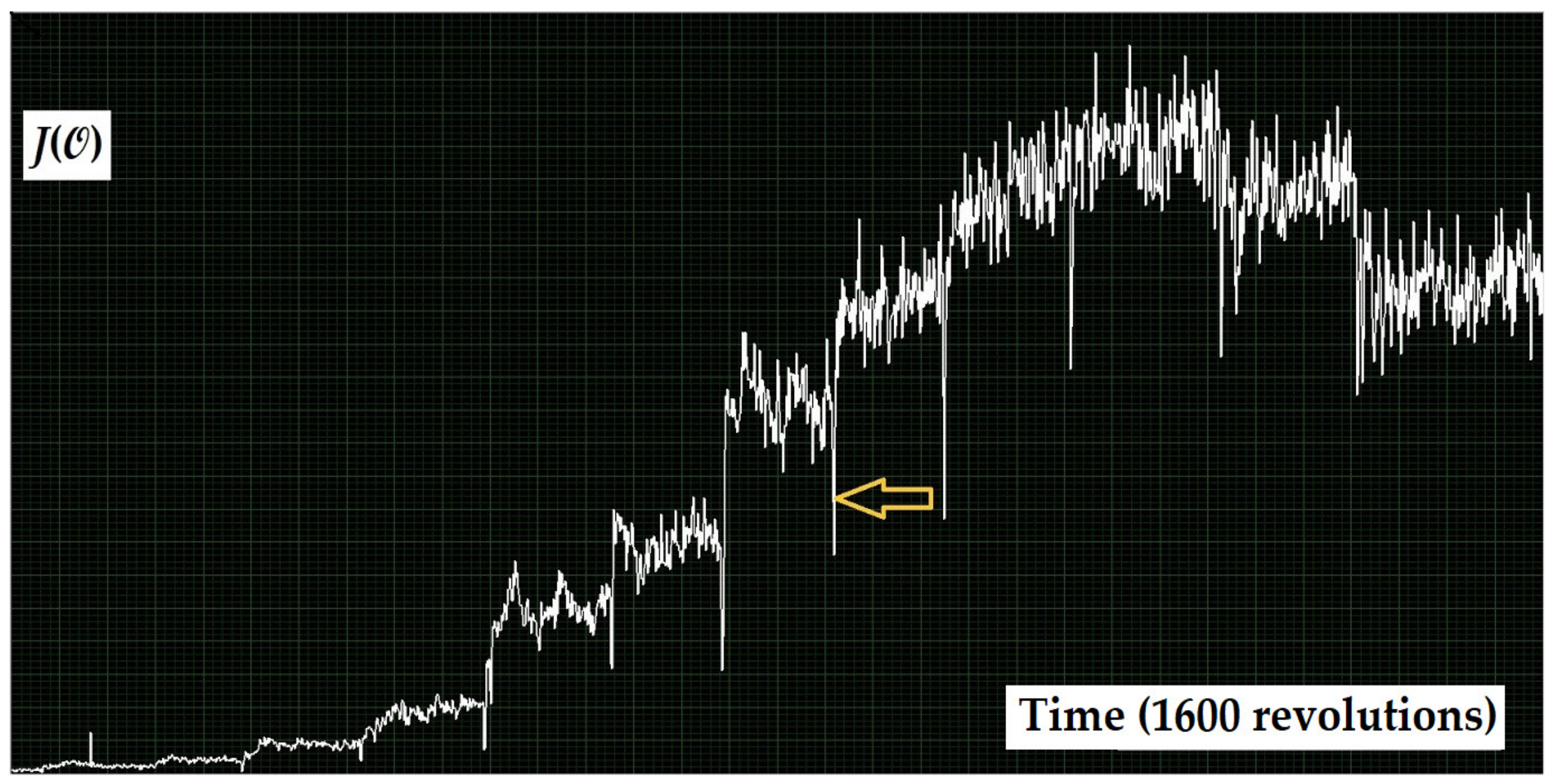
Difficulty on Kaplan turbines. On Francis units, the entire path of transmission of the structure-borne sound from the blade surface to the sensor on the turbine shaft is metallic. On Kaplan units, however, there is a hurdle in the blade mechanism. It causes interruptions of signal transmission during runner-blade adjustments at moments of load change (Figure 7). The resulting error can, however, be easily eliminated in the signal processing.
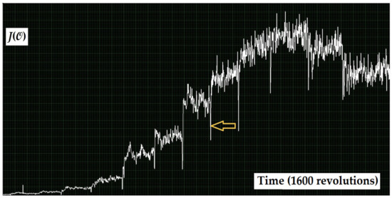
Figure 7.
Time record of a not strongly averaged cavitation-intensity estimate acquired by the sensor on the turbine shaft of a Kaplan unit, the load of which, , was sequentially increased in several steps. In the moments of load change the transmission of the structure-borne sound was interrupted; the arrow points to one of such moments. Under the constant load, the transmission was good.
Sensor on the turbine shaft vs. sensors on the guide vanes. A sensor on the turbine shaft collects with equal sensitivity excitation from cavitation on both sides of the runner, while sensors on the guide vanes prefer the runner’s high-pressure side and the runner-blade tip. However, the sensor on the turbine shaft hardly recognises the origin of the signals while the sensors on the guide vanes introduce a spatial resolution which is a good step towards this goal. A combination of both sources of data enables otherwise unattainable conclusions to be reached. Here, final estimates of the mean global cavitation-intensity values should be taken from the sensor on the turbine shaft and the information on the spatial distribution of cavitation from the sensors on the guide vanes.
Other sensor locations. Suitable candidates for additional or alternative sensor locations are circumferentially distributed points on the draft tube if it is accessible. However, true spatial resolution is reached here only by fast pressure transducers, which are difficult to be installed; the sensors which pick up the structure-borne sound from the metal structure are less effective in this respect since the structure integrates excitation from various locations.
Time resolution. To distinguish between the cavitation patterns caused by different inflow segments, such as pulse patterns in Figure 4 and Figure 5, Φ-resolved measurement with KVB – typically 2000 – samples per revolution is needed. A further requirement on the time resolution is that single signal samples should be sufficiently shorter than fast cavitation pulses. Thus, the width of the aperture in a sample-and-hold element of the signal sampler should be of the micro-second order, and the pass band of the electronics should be suitably wide. This does not imply such a short sampling period: with the basic data (1)/(2) calculated as in 4.1, it is not necessary to sample the cavitation pulse waveform in accordance with the Nyquist theorem. However, single samples of the cavitation signal should be read without time averaging; such averaging is allowed only after squaring the samples.
Nonlinear sensors? Instead of linear sensors, some of those that yield true root-mean-square value of the signal can also be used. Their outputs should also be squared and averaged as in (1) and (2). The applicability of such sensors depends on their bandwidth and the averaging time of the detectors that might be incorporated in them: the sensors must meet the requirements on the time resolution as specified above.
Integral signal signatures. Attractive signal signatures such as an envelope spectrum deliver easily interpretable results but leave unused a part of the information on the details of cavitation generation. The multidimensional procedure is more complicated in interpretation but preserves most of the theoretically achievable information content of the deterministic space/time description of the cavitation process.
Processing synchronised with runner rotation. The presented procedure emphasises contributions from cavitation with a basic once-per-revolution rate and is thus optimised for cavitation on and around the runner. By averaging over revolutions, it suppresses other periodicities and is thus not sensitive to the (most often non-erosive) free cavitation vortices in the draft tube.
Independent processes. Cavitation in a turbine consists of VB (in the considered case, roughly 100, and in Francis units, even 1000) independent or almost independent processes. Although in a well-designed, well-manufactured and well-serviced turbine, moderate differences among these processes and their low variability in time can be expected, a deterioration effect that influences only some of the processes may pass unnoticed if only global cavitation intensity is checked. Thus, even for routine monitoring and certainly in a diagnostic test, selective analysis of the cavitation patterns and cavitation mechanisms is needed, and only efficient spatial averaging can provide reliable global assessment.
Erosion assessment. This task, still not fully achieved vibro-acoustically, is supported by the recognition of cavitation mechanisms in the multidimensional method. Here, first, the mean squares of outputs from linear sensors should be assessed. This action decouples the independent mechanisms, and only after that the proposed rule for transforming the cavitation intensity estimates to the erosion assessments can be used.
5. Case Analysis
The notions introduced in Chapter 4 are applied to the data acquired on the prototype and models listed in Chapter 3 and are further developed in what follows. Not all the steps of the procedure are presented in detail, and not all the tools of the multidimensional method are included. Here are the basic data on the plant and the prototype turbine tested: run-of-river Kaplan; 6–9.5 m head; 300 m3/s max; 22 MW max; 75 rpm; semi-spiral; 11+1 stay vanes; 24 guide vanes; 4 runner blades.
5.1. Recognising Turbine Parts
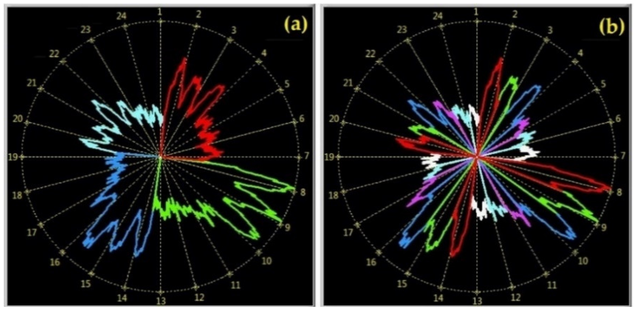
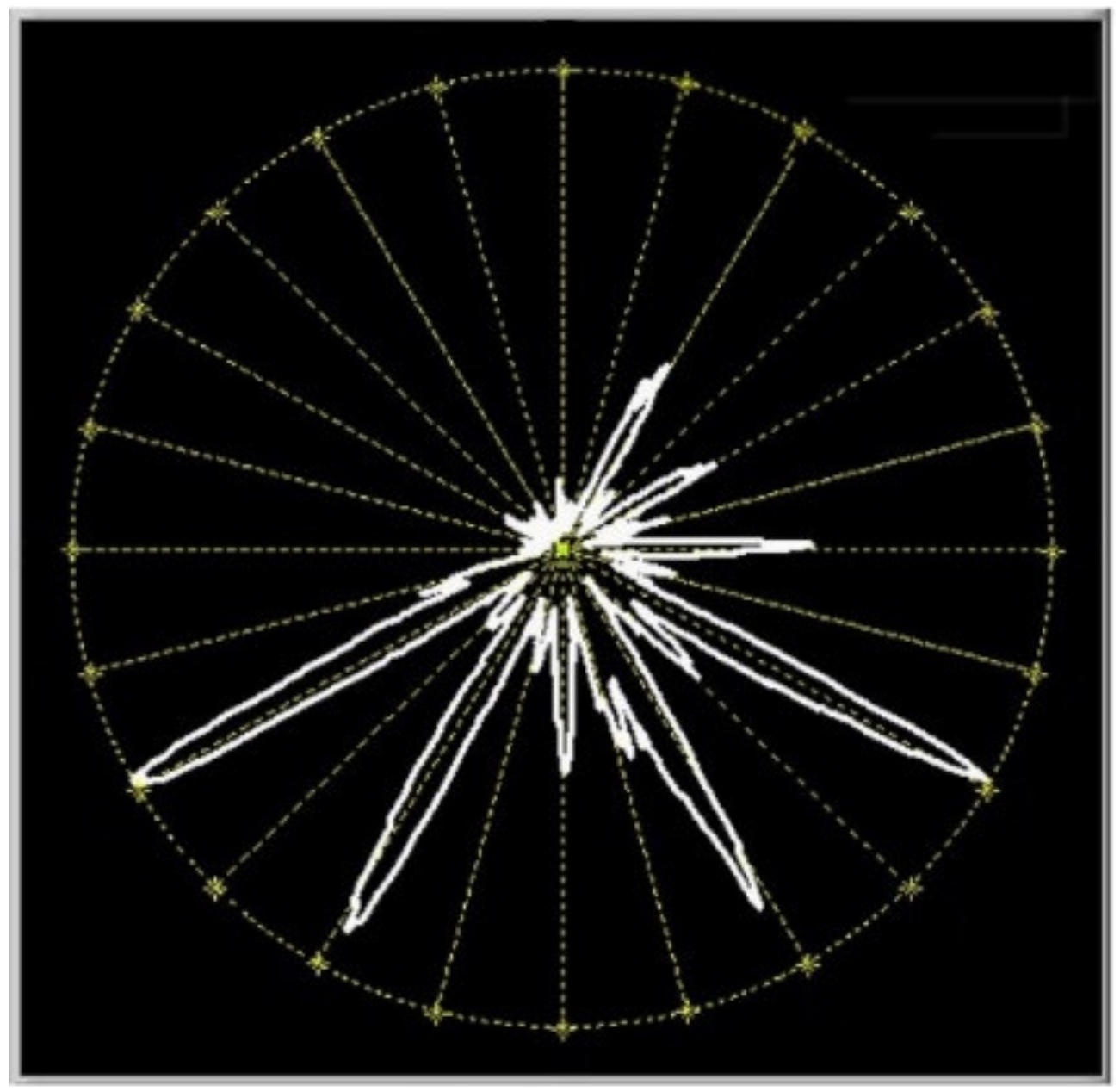
Although the numbers of guide vanes and runner blades in the considered turbine, 24:4, are inconvenient, traces of the runner blades and the guide vanes can be recognised quite clearly in the modulation curves (cavitation intensity measured by a sensor on one guide vane vs. the instantaneous angular position of the runner, Figure 8). In some cases, such an analysis yields directly applicable conclusions (Figure 9).
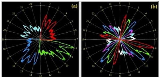
Figure 8.
Different colours – different turbine elements: (a) runner blades, (b) guide vanes (I(,Θ,Φ) for one , and one Θ, with I as the radial and Φ as the angular coordinate of the polar graph, the scale of Φ being expressed in guide-vane distances).
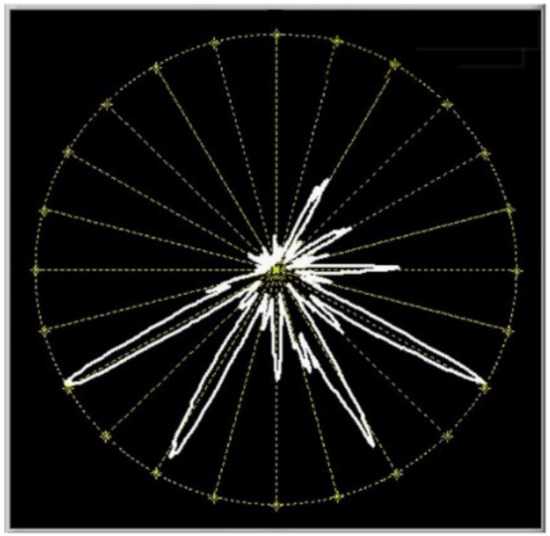
Figure 9.
At this operation point, the impact of the stay vanes on the flow is decisive for cavitation.
5.2. Introductory Turbine Characteristics
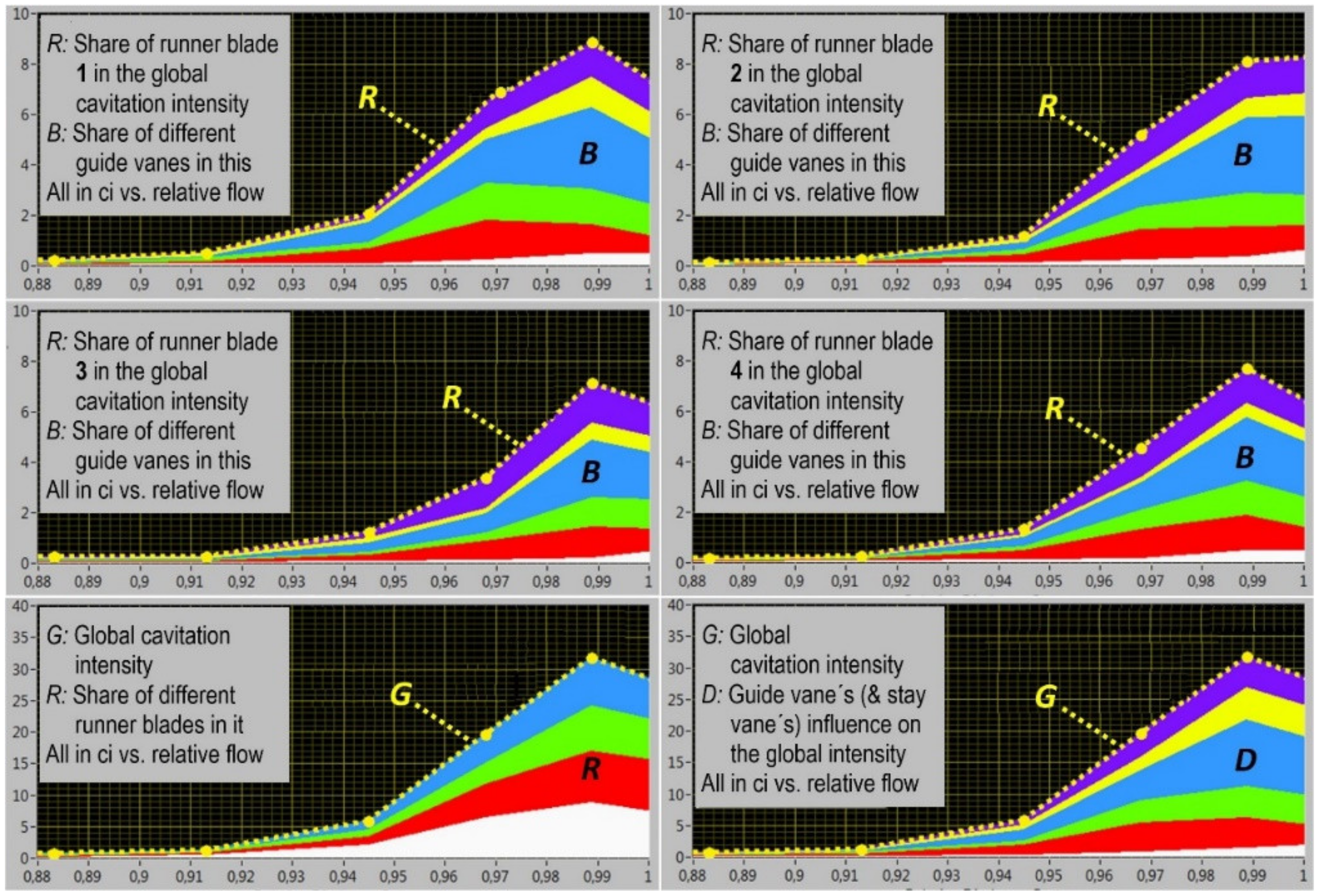
The analysis above yields the useful introductory characteristics of a turbine related to the runner cavitation (Figure 10):
- Basicturbine cavitation characteristics: Separately estimated cavitation intensity caused by each guide-vane/runner-blade pair
- Runnercavitation characteristic: Cavitation intensity related to each runner blade (averaged over all guide vanes)
- Distributorcavitation characteristic: Influence of each guide vane including other turbine elements upstream of the runner (averaged over all runner blades)
- Globalcavitation characteristic: Global cavitation intensity in a turbine (averaged over everything).
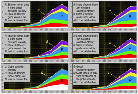
Figure 10.
Four types of introductory turbine cavitation characteristics (the model of the turbine in operation, on specific head and cavitation-number values), all expressed as components of the mean global cavitation characteristic I(), G. All 4 runner blades are presented, but only 6 guide vanes (those visible in Figure 8b); the others make negligible contributions.
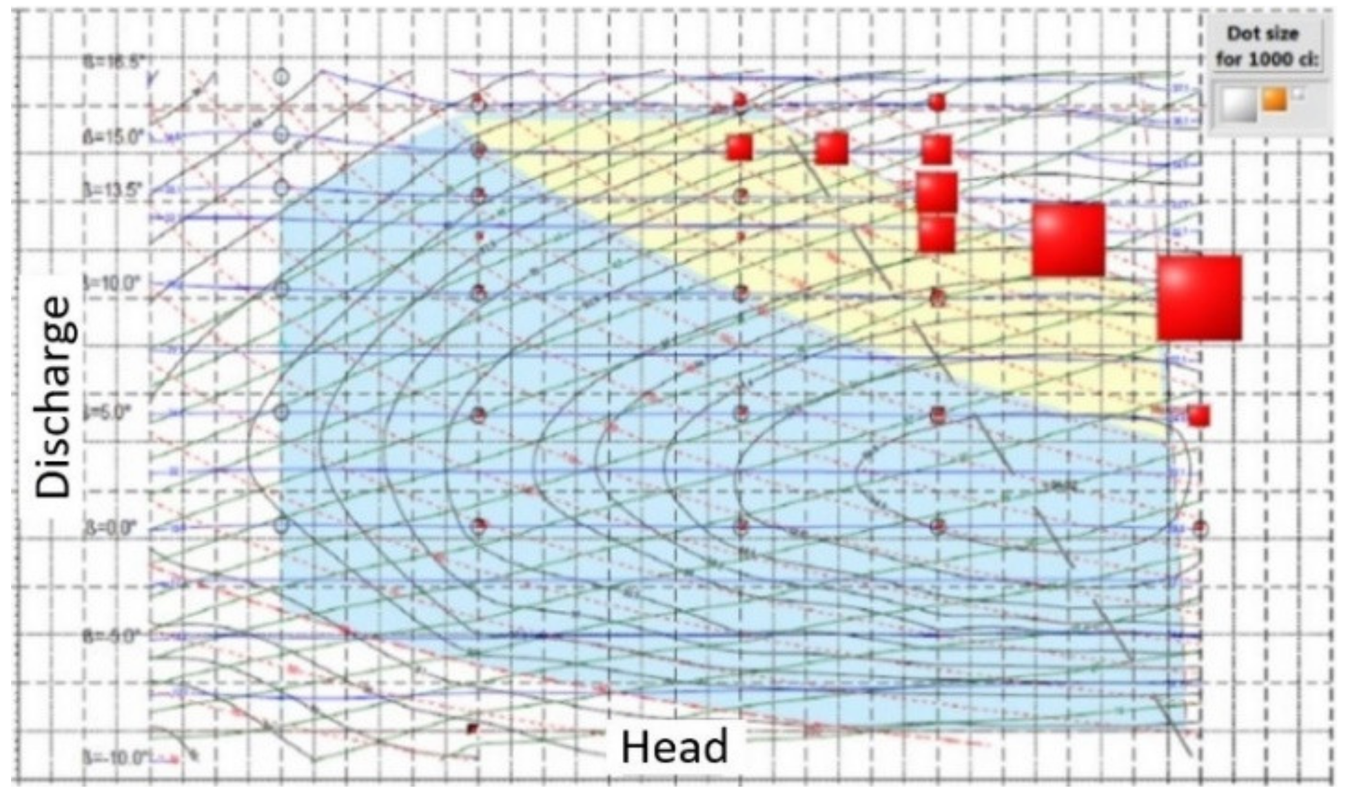
Another useful cavitation-intensity presentation is illustrated in Figure 11.
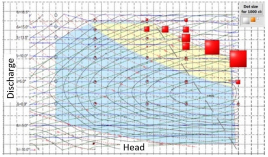
Figure 11.
Mean global cavitation intensity I() above a turbine hill chart. The linear size of the red squares represents the cavitation intensity.
5.3. Classification of Cavitation-Intensity Data
According to the spatial circumferential location of the cavitation mechanism: Local describes one spatial circumferential segment or one turbine part (a blade, a vane, etc.); Global describes the entire turbine: averaged over all segments or turbine parts.
According to the temporal position within a turbine revolution: Instantaneous describes the time (angular) dependence within the revolution; Mean averaged over the entire revolution.
In all the definitions, deterministic values of the cavitation intensity are used; their estimates are obtained by averaging over a sufficiently high number of revolutions.
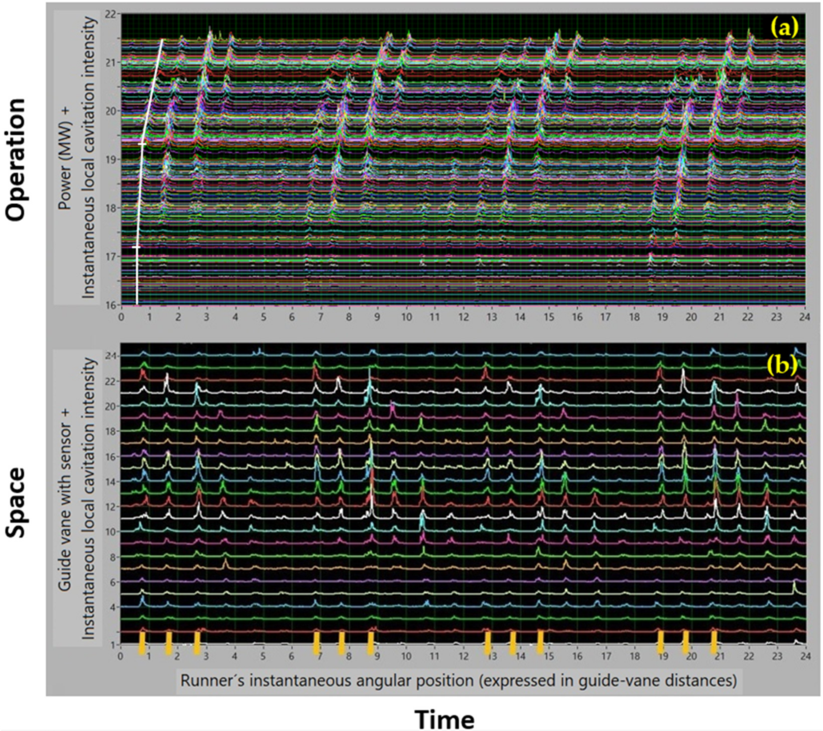
Further examples, Figure 12: Instantaneous, local.
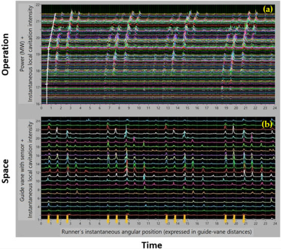
Figure 12.
Two typical formats of the instantaneous cavitation intensity presentation (turbine in operation, prototype) illustrating the use of the three dimensions of data: (a) Measured by one sensor on all available power outputs (I(,Θ,Φ) above Φ and for one Θ) (b) Measured at one operating point using the sensors on all guide vanes (I(,Θ,Φ) above Φ and Θ for one ). The peaks of the cavitation intensity are shifted circumferentially with increasing load (three white lines in a). The trends denoted by the three lines correspond to cavitation-free operation and two distinct cavitation mechanisms.
5.4. Influence of Runner Blade vs. Guide Vane Correlation
The results of the prototype index test combined with the vibro-acoustical cavitation test (Figure 13) shows that the cam optima for efficiency and cavitation do not coincide. Checking cavitation during the index test is recommended.
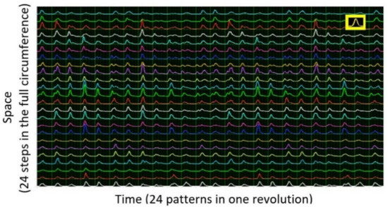
In the off-cam operation (but also in the high-head high-flow on-cam operation), many or all the guide vane/runner-blade pairs contribute to the cavitation process. Figure 14 illustrates the resulting waveform of the instantaneous cavitation intensity. It consists of similar peaks that are almost periodic in both time and space. This can cause strong vibration (see Appendix 3).
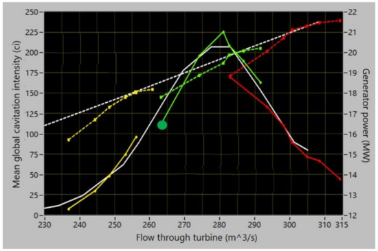
Figure 13.
Cam check based on relative efficiency: white – on cam, coloured – off cam; solid lines – cavitation intensity I(), dashed lines – generator power.
Figure 13.
Cam check based on relative efficiency: white – on cam, coloured – off cam; solid lines – cavitation intensity I(), dashed lines – generator power.
5.5. Stationary and Rotating Cavitation Mechanisms
If the traces of the runner blades, clearly separated as in Figure 8a, are recognised in the records such as those in Figure 12b (four similar groups of peaks), and if, in them, the quasi-columns of instantaneous intensity peaks such as those above the short yellow lines in Figure 12b are followed, it becomes clear that there are, in the considered turbine, two types of cavitation mechanisms:
- one that consists of cavitation fixed to the runner blades and is rotating, and
- another which stands still in the non-rotating space, is thus fixed to individual guide vanes and can be described as stationary.
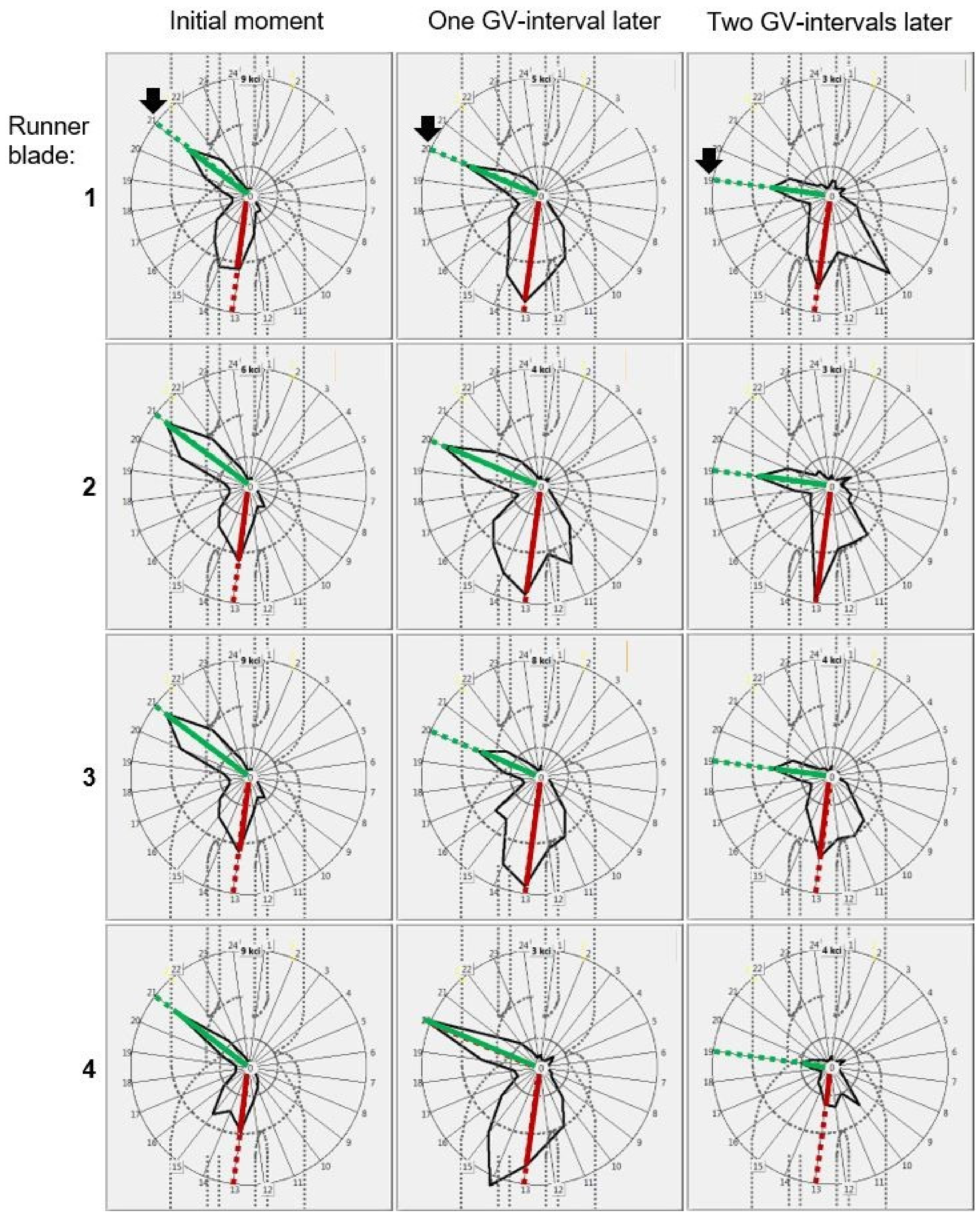
For one operation point (on the prototype), this situation is presented in Figure 15. Here, the ‘GV-interval’ stays for the time or angular interval between neighbouring guide vanes in Figure 12b, i.e., the step between the yellow lines.
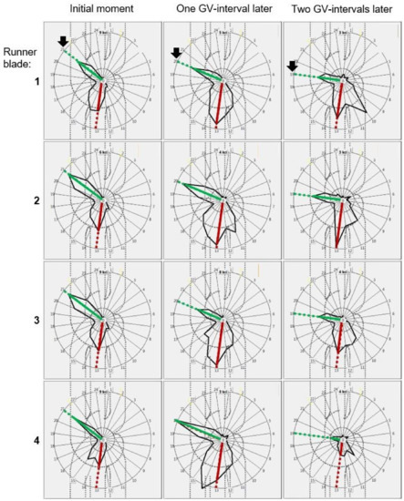
Figure 15.
The patterns of the instantaneous cavitation intensity I(,Θ,Φ) at a constant , denoted with green lines lie in subsequent moments (three columns – three subsequent vales of Φ) in different directions (the sensor position Θ is the angular coordinate of the polar diagram, I the radial coordinate): in these three different moments, the green patterns are registered by the sensors lying on subsequent guide vanes. They thus represent the cavitation patch that travels with the blade (cf. the black arrows). The other patterns, denoted by the red lines, are more or less stationary. An analysis such as this is one of the ways to distinguish between the stationary (red) and rotating cavitation mechanisms (green).
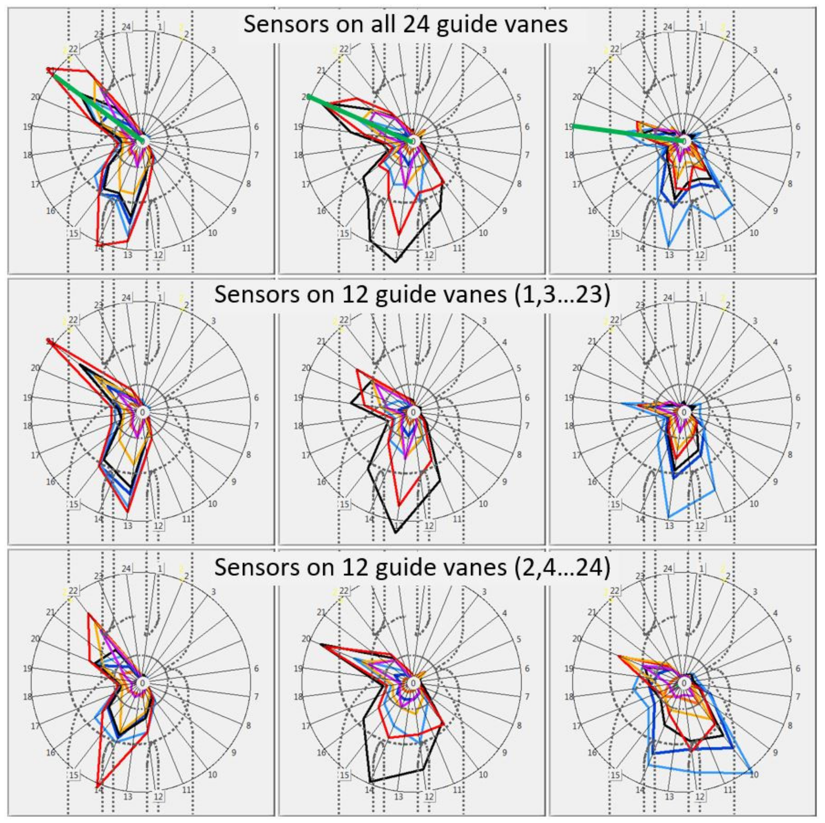
5.6. Necessary Number of Sensors
As can be seen in Figure 16, the arguments that, based on the measurements on 24 guide vanes (presented in Figure 15), made it possible to distinguish between rotating and stationary cavitation mechanisms are not clearly supported by the results of the measurements with 12 sensors only. Therefore, having sensors on all guide vanes is highly recommended.
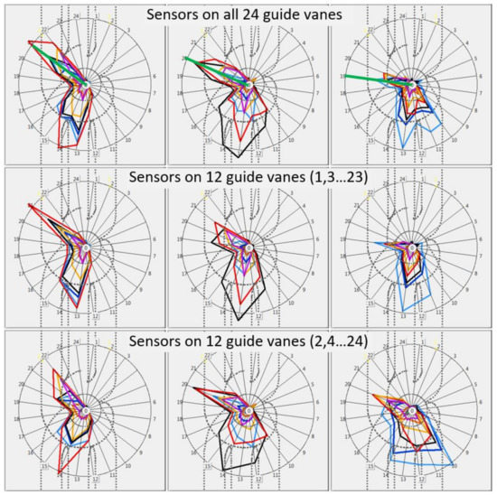
Figure 16.
The analysis as in Figure 15 made for several values, with 24 sensors (the first row), and the same with 12 sensors (the other two rows) points to the importance of using as many sensors as possible.
6. Cavitation on Prototype: Diagnostic Results
The object of the diagnostics – erosion as found in the last overhaul before the diagnostic test – is described by the photograph in Figure 17. Clearly, the erosion is due to two cavitation mechanisms: runner blade tip and runner blade surface (also hereinafter abbreviated to tip and surface). The seven diagnostic results on such cavitation are shown in Figure 17, Figure 18, Figure 19, Figure 20, Figure 21 and Figure 22 and are listed below. The steps of their derivation, based on the tools described in Chapter 4, are documented in Appendix 1.
- (1)
- The two cavitation mechanisms are successfully recognised vibro-acoustically.
- (2)
- Their locations with respect to the surrounding turbine parts are determined:Each of the 24 independent patches of the tip cavitation group is stationary in the still space; each one is fixed to the respective guide vane.The patches of the surface cavitation group, which occur on all the four runner blades, are stationary in the rotating frame of reference; they rotate with the respective blade.
- (3)
- The simplest quantification of the cavitation intensity, through the global mean value, i.e., at each operation point, by one value for each of the two groups of mechanisms and for their cumulative effect equal to the sum of the values for the two groups, is shown in Figure 17.
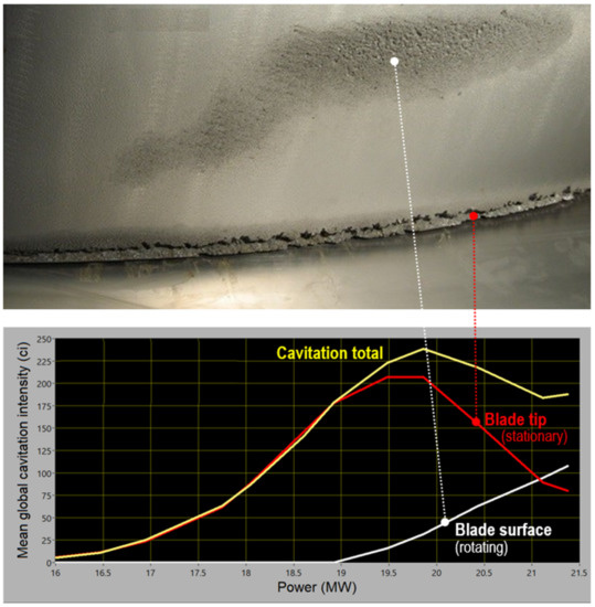
Figure 17.
Cavitation-erosion photograph, typical of all four runner blades, as found in an overhaul, and the simplest quantitative description of the total cavitation intensity and the intensities of the two groups of mechanisms.
Figure 17.
Cavitation-erosion photograph, typical of all four runner blades, as found in an overhaul, and the simplest quantitative description of the total cavitation intensity and the intensities of the two groups of mechanisms.
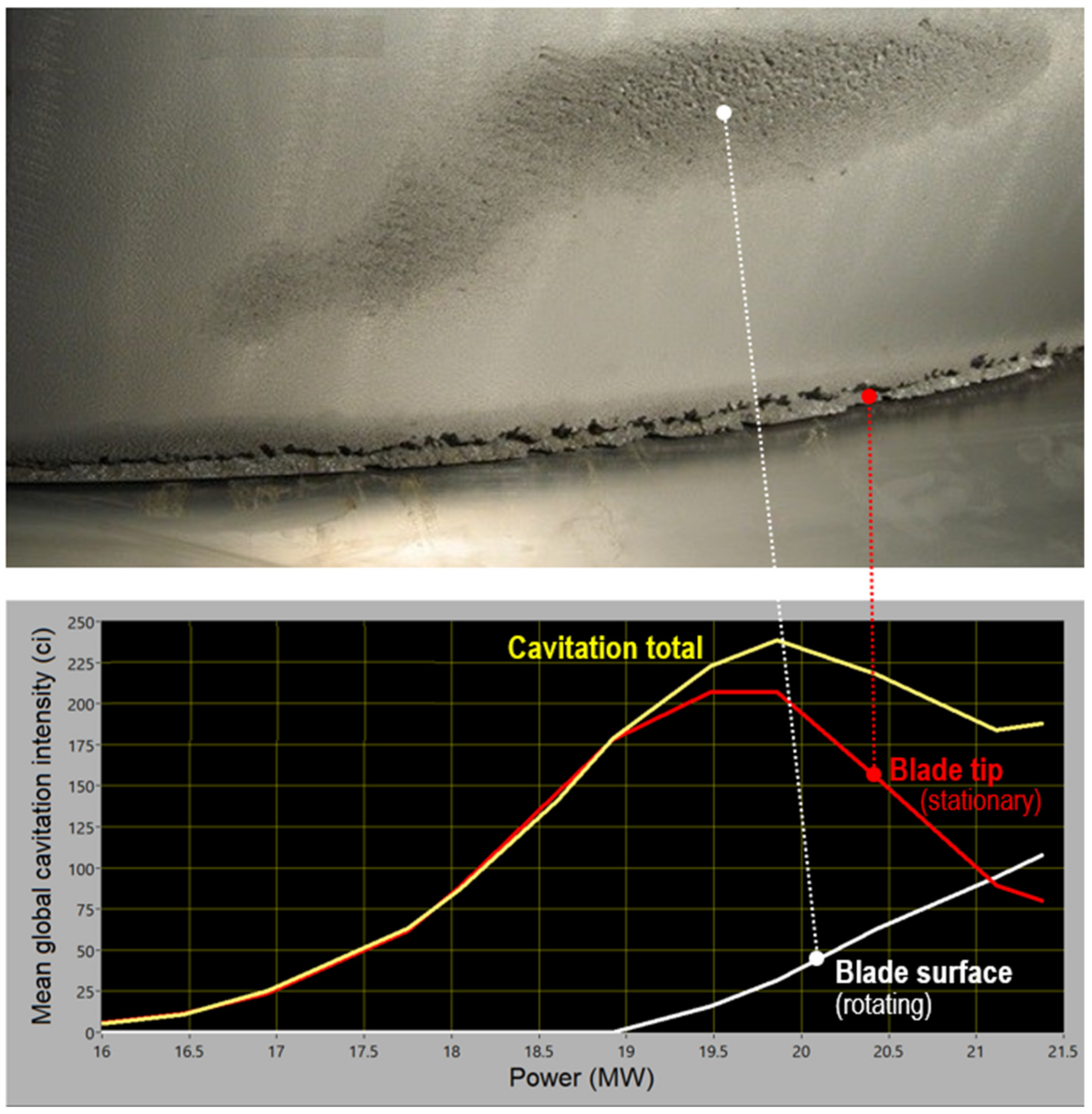
- These results can be used for operation optimisation, directly or transformed via (18)/(19) with the sum over m = 1 and 2 for the two groups, into relative predictions of the erosion rate.Three levels of cavitation description can be followed:- direct, via cavitation intensities;- via the non-normalised prediction of the erosion rate based on the km-values made equal to the k from (16), and unspecified Cm’s, also assumed equal;- performing calibration of Cm’s while assuming km’s as in (16), this being organised as steady tracking of the cavitation intensity between two visual inspections and comparing the accumulated cavitation intensity transformed into the erosion rate with direct estimation of the metal loss due to each of the two groups of mechanisms;- performing three or more calibrations such as this and also assessing the km-values.
- (4)
- A situation with the rotor-stator interaction as specified in Figure 18 and Figure 19 is found. This gives insights in the causes of cavitation.The intake channel C causes no problems.The strongest tip cavitation occurs in channel B; weaker tip cavitation occurs behind all the guide vanes.The surface cavitation is caused by the flow disturbances stemming from the inflow through channel A.
- (5)
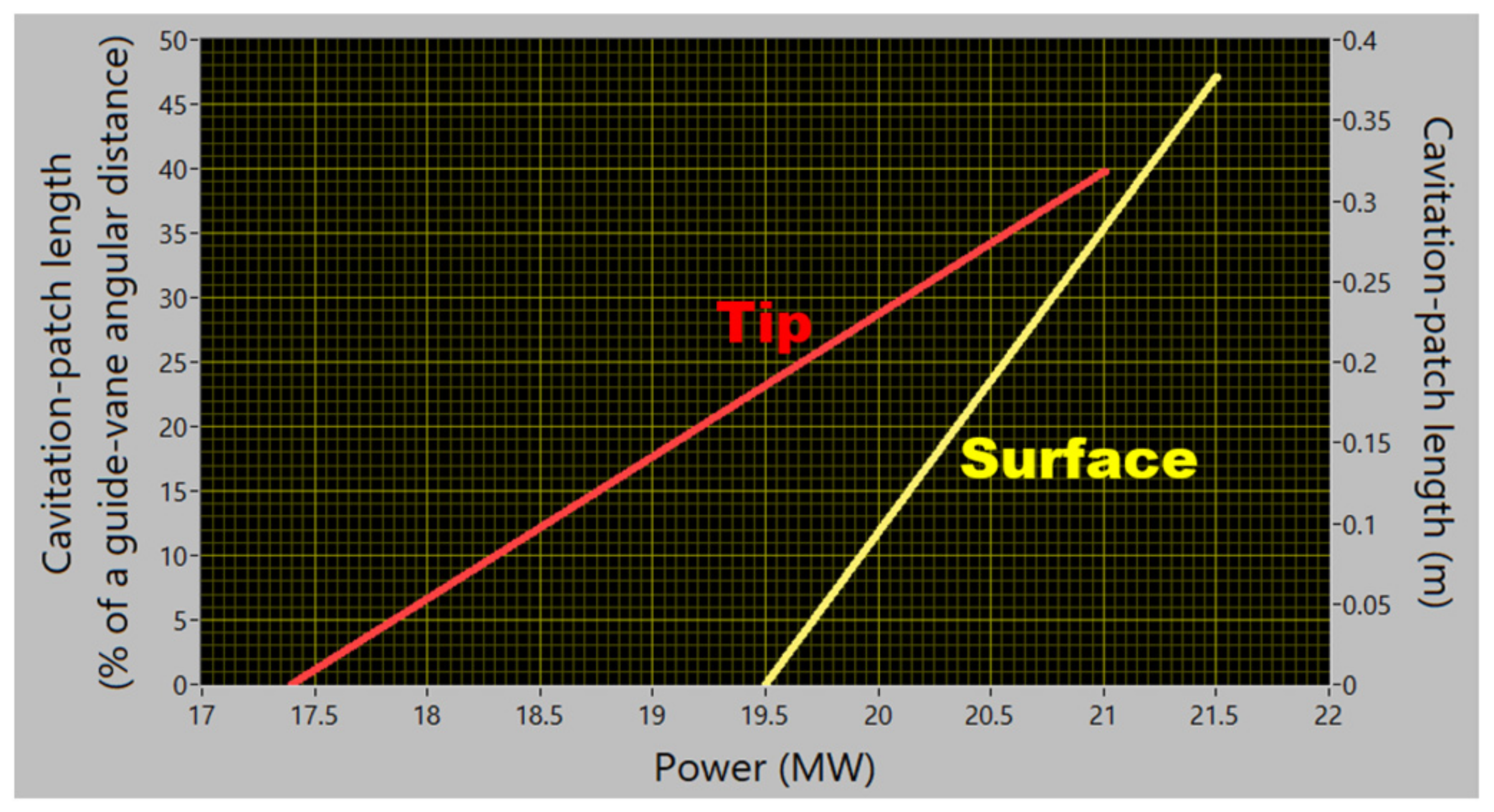
- The average size of the cavitation patches is also vibro-acoustically assessed (Figure 20). When the mechanisms are fully developed, the patches occupy up to a half of the distance between the neighbouring guide vanes. The size of the surface cavitation rises with the increasing load twice as fast as that of the tip cavitation.
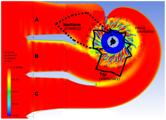
Figure 18.
Circumferential distribution of the mean local cavitation intensity drawn above the computational-fluid-dynamics prediction of the local pressure field in front of the runner. The polar curves repeat those of Figure 19 with the surface/tip scale ratio reduced by 2.
Figure 18.
Circumferential distribution of the mean local cavitation intensity drawn above the computational-fluid-dynamics prediction of the local pressure field in front of the runner. The polar curves repeat those of Figure 19 with the surface/tip scale ratio reduced by 2.
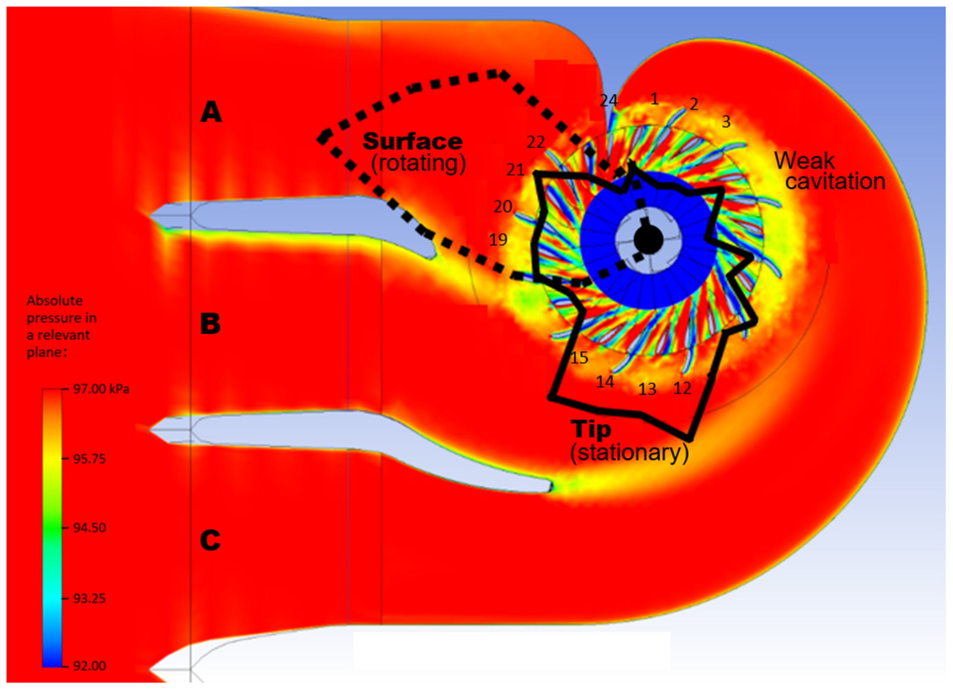
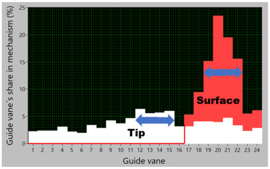
Figure 19.
A full quantitative description of the mean role of the guide vanes in each of the two groups of mechanisms. The guide-vane intervals with high cavitation intensity are denoted by the arrows here and by their numbers in Figure 18.
Figure 19.
A full quantitative description of the mean role of the guide vanes in each of the two groups of mechanisms. The guide-vane intervals with high cavitation intensity are denoted by the arrows here and by their numbers in Figure 18.
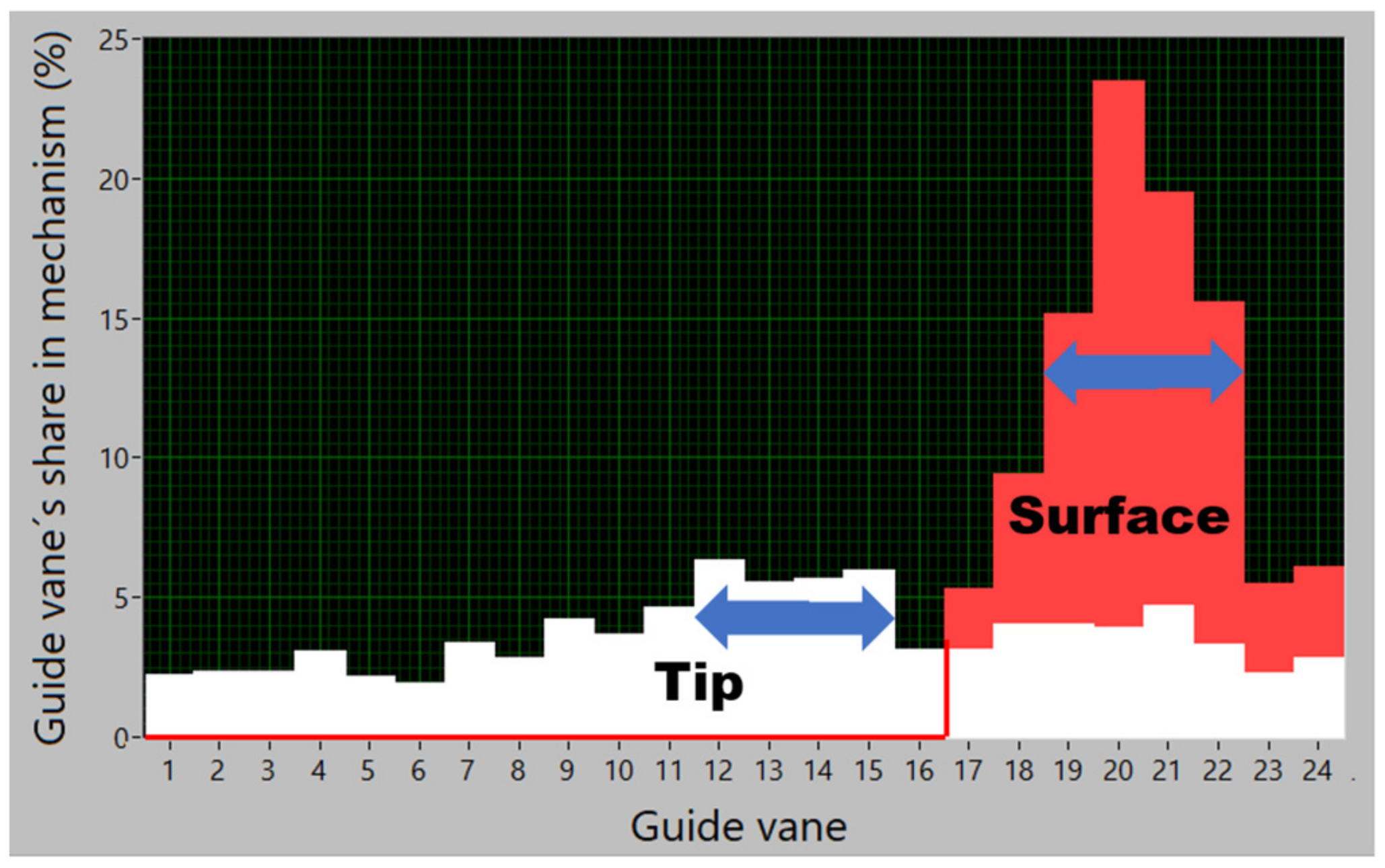
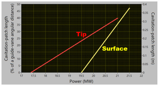
Figure 20.
The vibro-acoustical estimation of the average circumferential size of the erosion patches caused by each of the cavitation mechanisms in the two groups of mechanisms.
Figure 20.
The vibro-acoustical estimation of the average circumferential size of the erosion patches caused by each of the cavitation mechanisms in the two groups of mechanisms.
- (6)
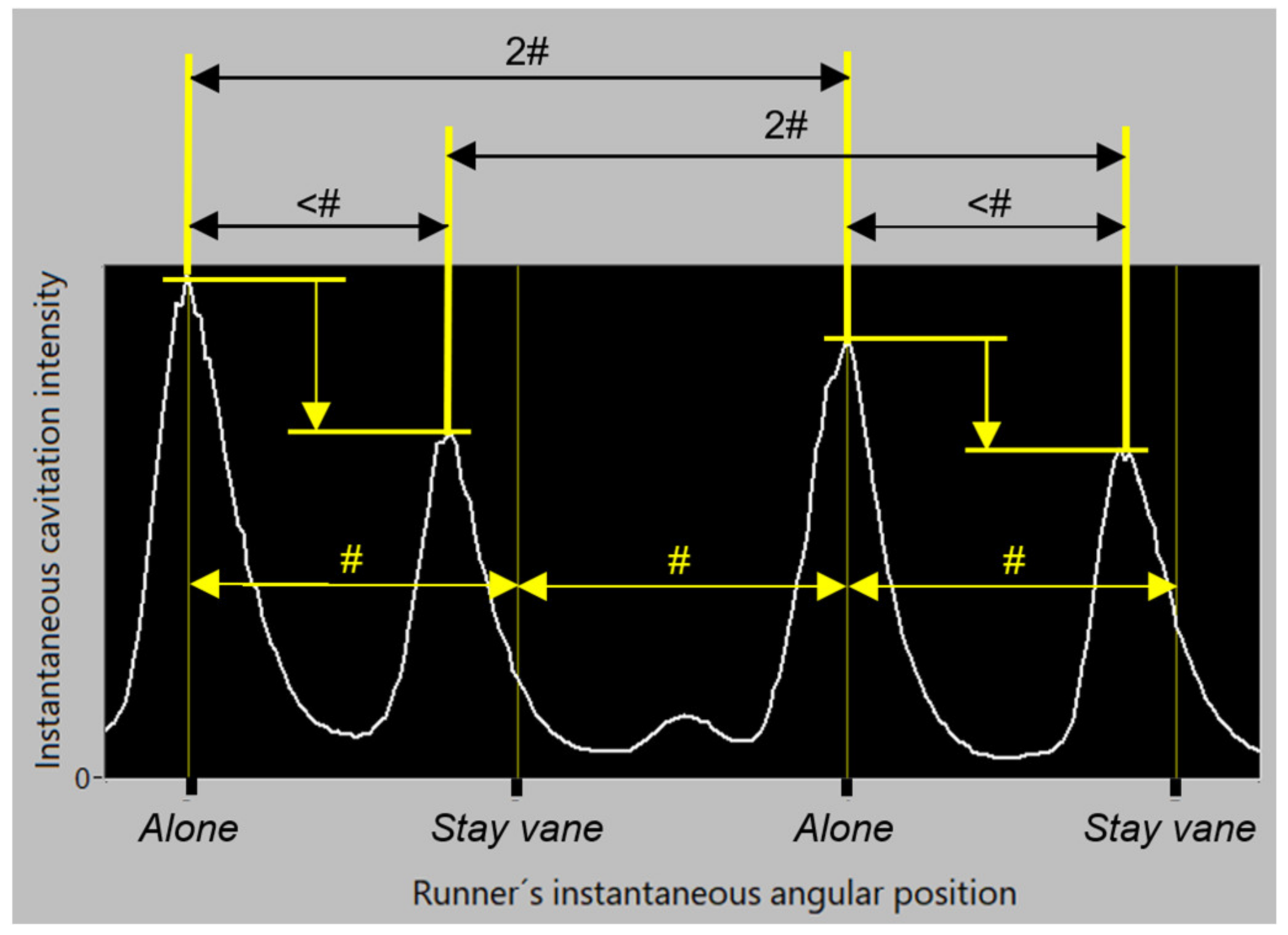
- The method also reveals systematic differences in cavitation behind the guide vanes that have stay vanes in front of themselves and those that stand alone, as well as deviations in the general time periodicity of the cavitation mechanisms (Figure 21).
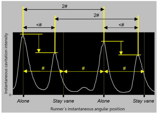
Figure 21.
(a) The cavitation intensity stemming from the guide vanes that stand alone is higher than from those that lie behind the stay vanes. (b) The delay between the peaks in an alone/not alone pair is shorter than the mean delay between the guide vanes, #. (c) In the response of one runner blade to the excitation coming from the guide vane, this mean period, #, is ca 20% shorter than the runner rotation period.
- (7)
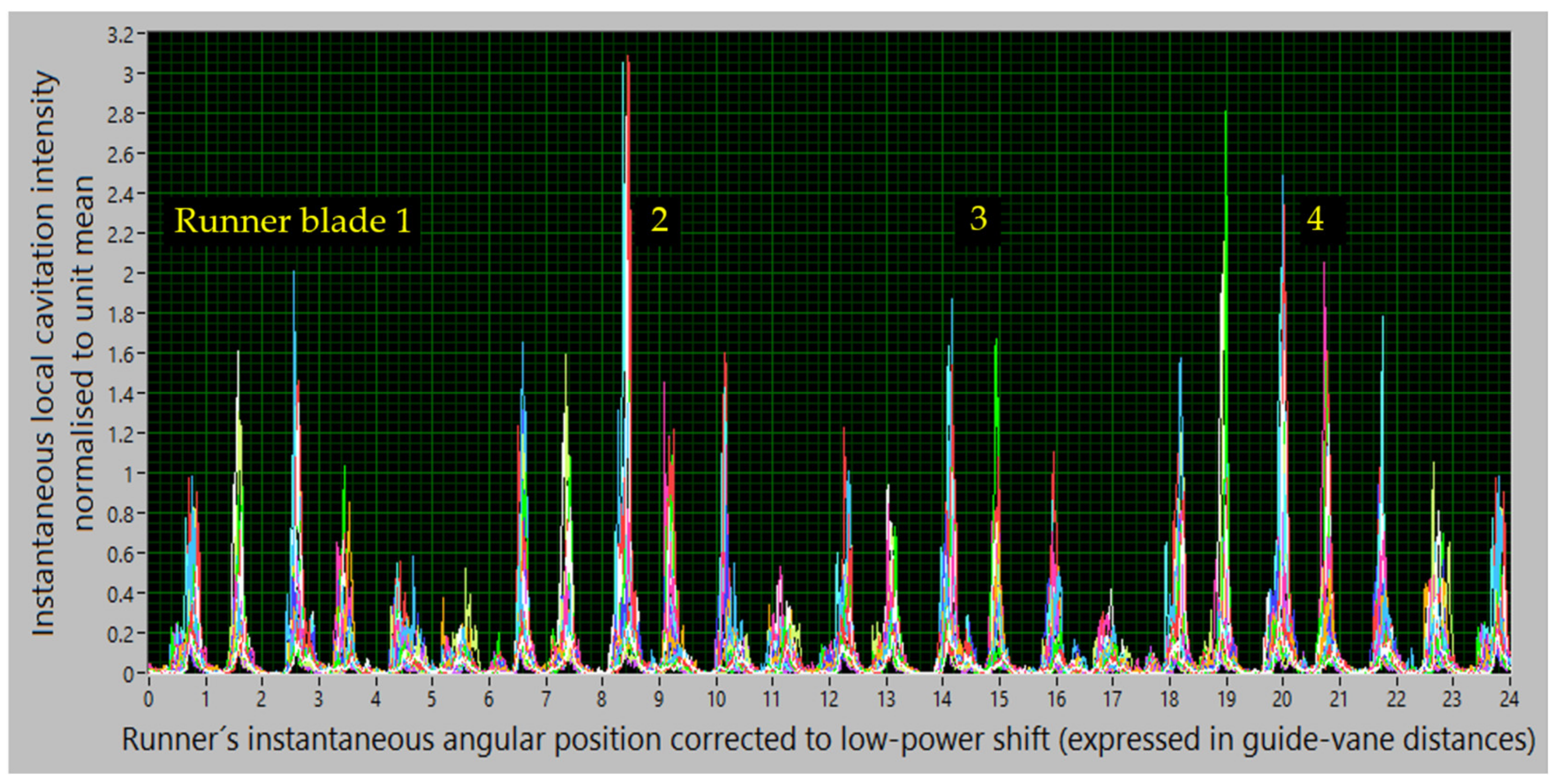
- The four runner blades do not have equal cavitation quality. Some of this can be seen in Figure 22. If necessary, these data can be analysed further.
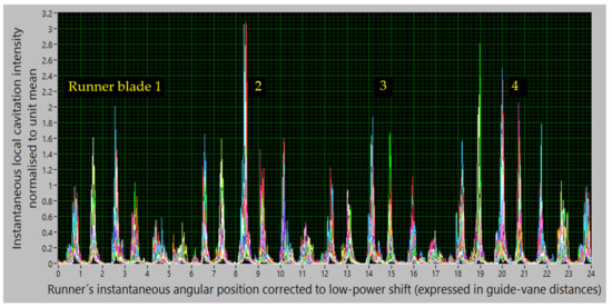
Figure 22.
These data acquired at many power values and corrected in a way to eliminate the circumferential shifts shown in Figure 12a demonstrate the differences in cavitation on the four runner blades. As can be seen, their interaction with the guide vanes varies in strength and distribution over the involved guide vanes.
7. Cavitation on Models: Comparison of Three Turbine Versions
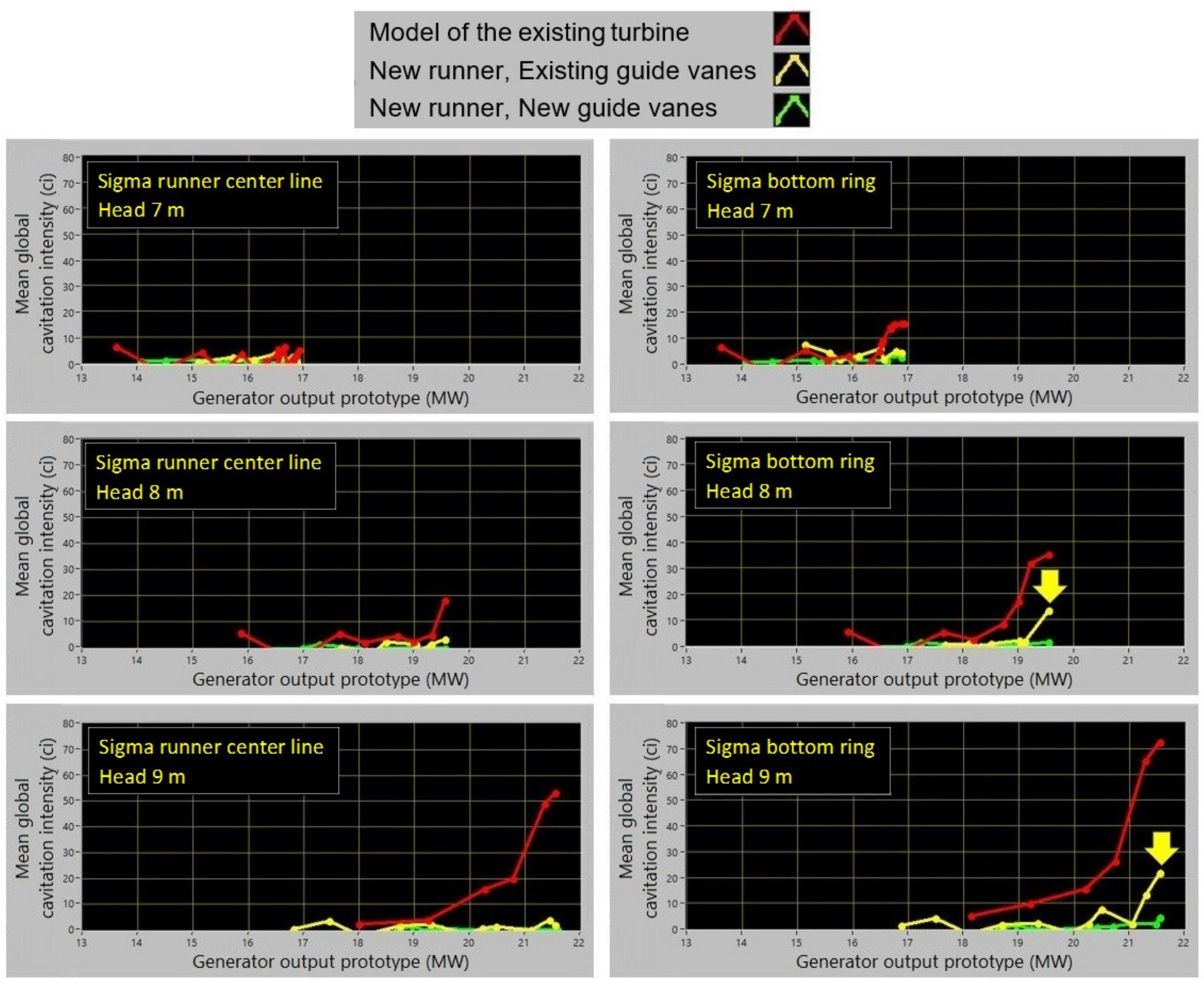
The mean global cavitation intensity, I(), the quantifier that describes the turbine by a single scalar value, and which is especially reliable in the multi-sensor estimation, is used to compare the three versions of the turbine (Figure 23).
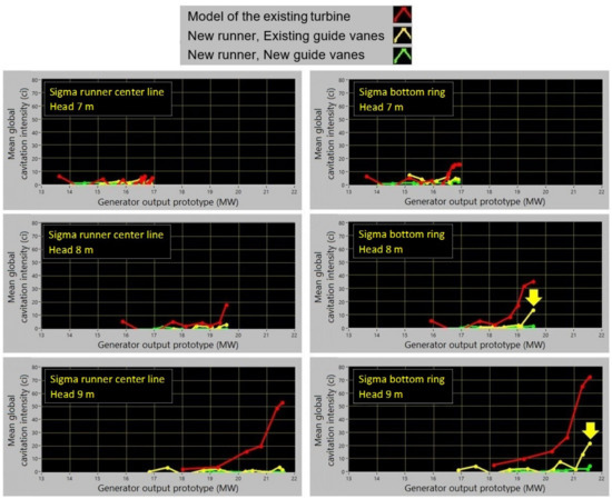
Figure 23.
Comparison of the three models.
The two new versions are much better than the version currently in use. At most operation points, these two versions are quite similar. However, in the high-head high-flow operation, the middle version tends towards increased cavitation intensity (the yellow arrows). Even if such an increase of cavitation intensity is considered acceptable,
the New-runner/New-guide-vanes version is recommended since the potential inaccuracy in the model-to-prototype prediction and prototype machining with given manufacturing tolerances might provoke stronger cavitation on even lower loads.
8. Conclusions
Korto’s multidimensional vibro-acoustical method for the diagnostics of turbine cavitation is based on a high number of spatially distributed sensors on the dry side of a turbine, and the signal and data processing that systematically and simultaneously analyses data in three dimensions: spatial, temporal, and operational. Directly or combining and analysing the primary results, the method delivers unbiased estimates of cavitation intensity and rich diagnostical data on cavitation mechanisms. The results can be used, on prototypes, for operation optimisation and for turbine cavitation-quality assessment, and, on models, as an additional tool for quantifying cavitation intensity. If used for long-term monitoring, the method also enables maintenance optimisation.
The theory of the method is presented and its application is illustrated on a Kaplan turbine. The method is applicable on Francis, Kaplan, bulb, and reversible pump turbines, as well as pumps. In the considered turbine, cavitation mechanisms for two erosion types found in an overhaul are vibro-acoustically identified, quantified, and analysed. Data pointing to the causes of the cavitation are derived. The cavitation quality of the three models is compared vibro-acoustically. It is also shown that developed cavitation can cause vibration with a rich line spectrum.
Author Contributions
B.B.: Methodology, theory, vibro-acoustical data acquisition, analysis, and interpretation. S.W.: Hydraulic aspects of the model tests. M.K.: Hydraulic aspects of the prototype tests. All authors have read and agreed to the published version of the manuscript.
Funding
This research received no external funding.
Conflicts of Interest
The authors declare no conflict of interest.
Nomenclature
| B | number of runner blades (-) |
| Bx() | Bx(,Θ) assumed equal in all sensors (ci) |
| Bx(,Θ) | non-cavitation background in the sensor on the guide vane at Θ, at the operation point (ci) |
| By() | non-cavitation background in the sensor on the turbine shaft, at the operation point (ci) |
| c | adjustment constant for the turbine-shaft channel (-) |
| C, Cm | turbine-specific constants in the erosion model (16)/(19) |
| ci | ad hoc cavitation-intensity unit |
| E, Em | erosion rate in the erosion model (16)/(19) (kg per 10000 h or alike) |
| I() | mean global cavitation intensity assessed by the sensors on the guide vanes at the operation point (ci) |
| Im() | m-th cavitation mechanism in I() or cJ() (ci) |
| Irot () | rotating mechanism in I() or cJ() (ci) |
| Ista () | stationary mechanism in I() or cJ() (ci) |
| Is(,Θ) | spatial dependence of the mean cavitation intensity (ci) |
| It(,Φ) | temporal dependence of the spatially mean cavitation intensity (ci) |
| Itr(,Φ) | temporal dependence of the rotating cavitation mechanism, resulting from a synthetic sensor focused on the rotating mechanism (ci) |
| I(,Θ,Φ) | spatial and temporal dependence of cavitation intensity assessed by the sensors on the guide vanes at the operation point (ci) |
| Ir(,Θ,Φ) | spatial and temporal dependence of cavitation intensity of the rotating cavitation mechanism at the operation point (ci) |
| rot() | total intensity of the rotating mechanism at the operation point (ci) |
| sta() | total intensity of the stationary mechanism at the operation point (ci) |
| rot(,Φ) | temporal dependence of the total intensity of the rotating mechanism at the operation point (ci) |
| sta(,Φ) | temporal dependence of the total intensity of the stationary mechanism at the operation point (ci) |
| J() | mean global cavitation intensity assessed by the sensor on the turbine shaft at the operation point (ci) |
| J(,Φ) | temporal dependence of cavitation intensity assessed by the sensor on the turbine shaft at the operation point (ci) |
| k, km | exponent in the erosion model (16)/(19) (-) |
| K | number of temporal samples taken within an angular pattern of cavitation intensity (-) |
| m | cavitation-mechanism number (-) |
| M | number of temporal samples taken within one revolution (-) |
| n | revolution number (-) |
| N | number of revolutions included in the result (-) |
| turbine operation point (set of quantities used to quantify the operation) | |
| b | safely non-cavitation operation point |
| o | operation point at which c is estimated |
| v | guide-vane number (-) |
| V | number of guide vanes (-) |
| x(,Θ,Φ,n) | output of the sensor on the guide vane lying at Θ with the runner in the revolution n in the position Φ at the operation point (e.g., for accelerometer m/s2) |
| y(,Φ,n) | output of the sensor on the turbine shaft with the runner in the revolution n in the position Φ at the operation point (e.g., for accelerometer m/s2) |
| Θ | angular position of the guide vane equipped with the sensors (spatial coordinate, discrete) (rad) |
| Θv | value of Θ for the guide vane v (rad) |
| Φ | instantaneous angular position of the runner (temporal coordinate, continuous) (rad) |
| sum over the cavitation mechanisms m | |
| sum over the guide vanes v behind which the rotating mechanism occurs (or dominates) | |
| sum over the guide vanes v behind which the stationary mechanism occurs (or dominates) | |
| <·> | averaging over the statistical ensamble |
| <·>n | averaging over N revolutions n |
| <·>Θ | averaging over Θ ∈ [0,2π) |
| <·>Φ | averaging over Φ ∈ [0,2π) |
| * | denotes erosive cavitation mechanism and sum over erosive mechanisms |
Appendix 1. Details of Prototype Diagnosis
As shown in Figure 15, the rotating cavitation mechanism is detected behind guide vanes 19, 20 and 21. As sketched in Figure A1, Figure A2, Figure A3, Figure A4 and Figure A5 below (where cav. int. stands for cavitation intensity), the range of the guide vanes behind which the rotating mechanism is active is found to be broader, from guide vane 18 to guide vane 22 or 23. Quantitatively, this result is shown in Figure 19. Based on this finding, the description of the two cavitation mechanisms presented in Figure 17, Figure 18, Figure 19 and Figure 20 and as prototype results (1)–(5) in Chapter 6 are derived. The steps of these analyses are reviewed below. The remaining prototype results (6) and (7) and Figure 21 and Figure 22 are self-explanatory.
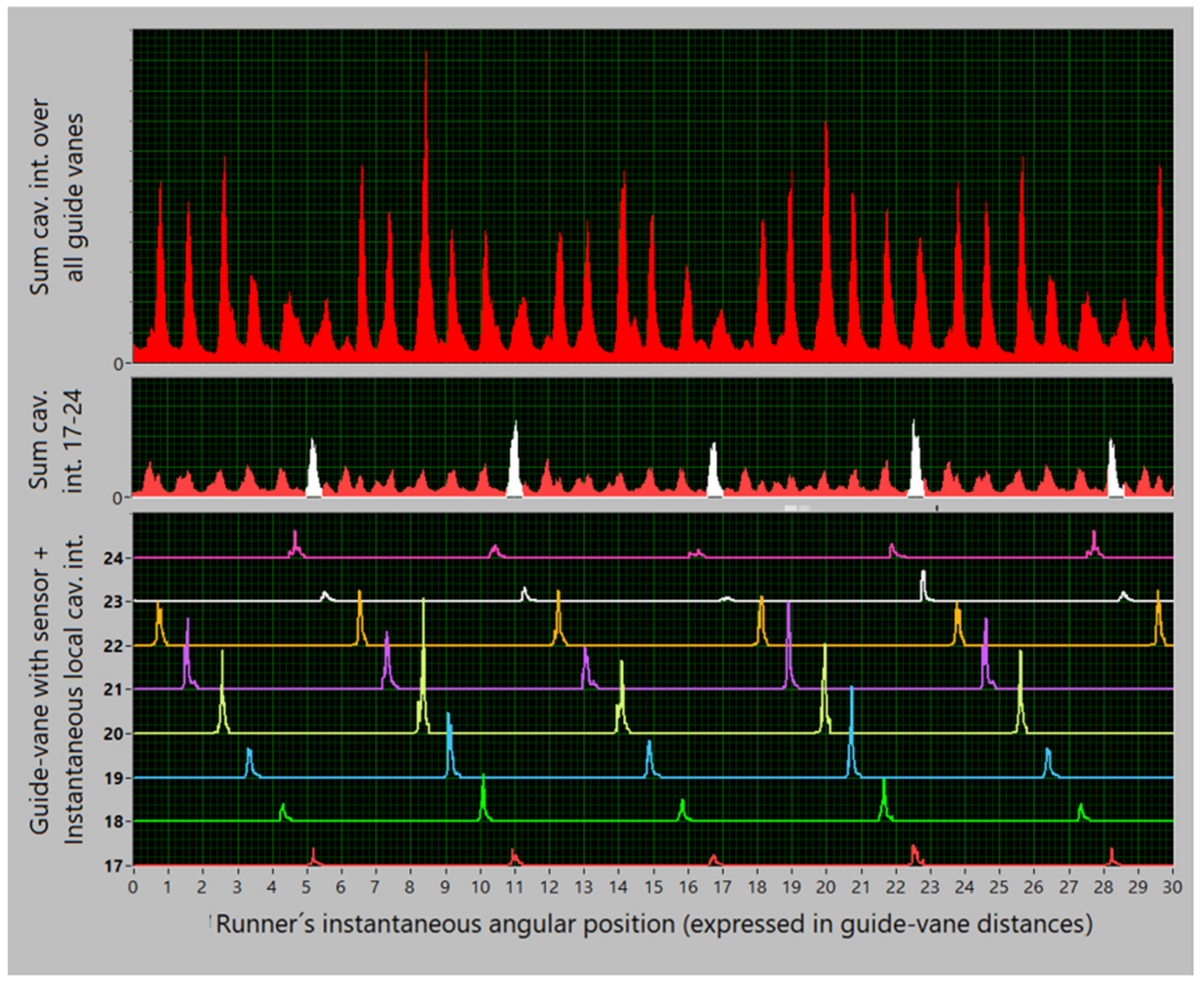
Figure A1—The graph at the bottom of this figure gives the input data for the analysis, which is a copy of the segment of Figure 12b with guide vanes 17–24 for one fixed operation point. The two upper graphs in Figure A1 are simple sums of the cavitation-intensity curves: the graph at the top, the sum of the curves from all guide vanes 1–24 (from Figure 12b); the graph in the middle, the sum of the eight curves selected for this analysis, 17–24; the scales in both graphs are equal. Comparing the form of these two curves, it can be seen that both represent fairly well the stationary cavitation mechanism via the temporal dependence (Φ on the horizontal axis) of its total intensity at a given operation point, , sta (,Φ); the sum in the middle graph has lower amplitudes since it collects intensities only from 8 of the 24 guide vanes.
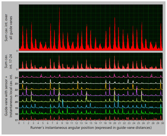
Figure A1.
From above: sta(,Φ) estimated by all v’s; sta(,Φ) estimated by v = 17–24; and I(,Θv,Φ) for v = 17–24; everything for a single , drawn above Φ.
Figure A1.
From above: sta(,Φ) estimated by all v’s; sta(,Φ) estimated by v = 17–24; and I(,Θv,Φ) for v = 17–24; everything for a single , drawn above Φ.
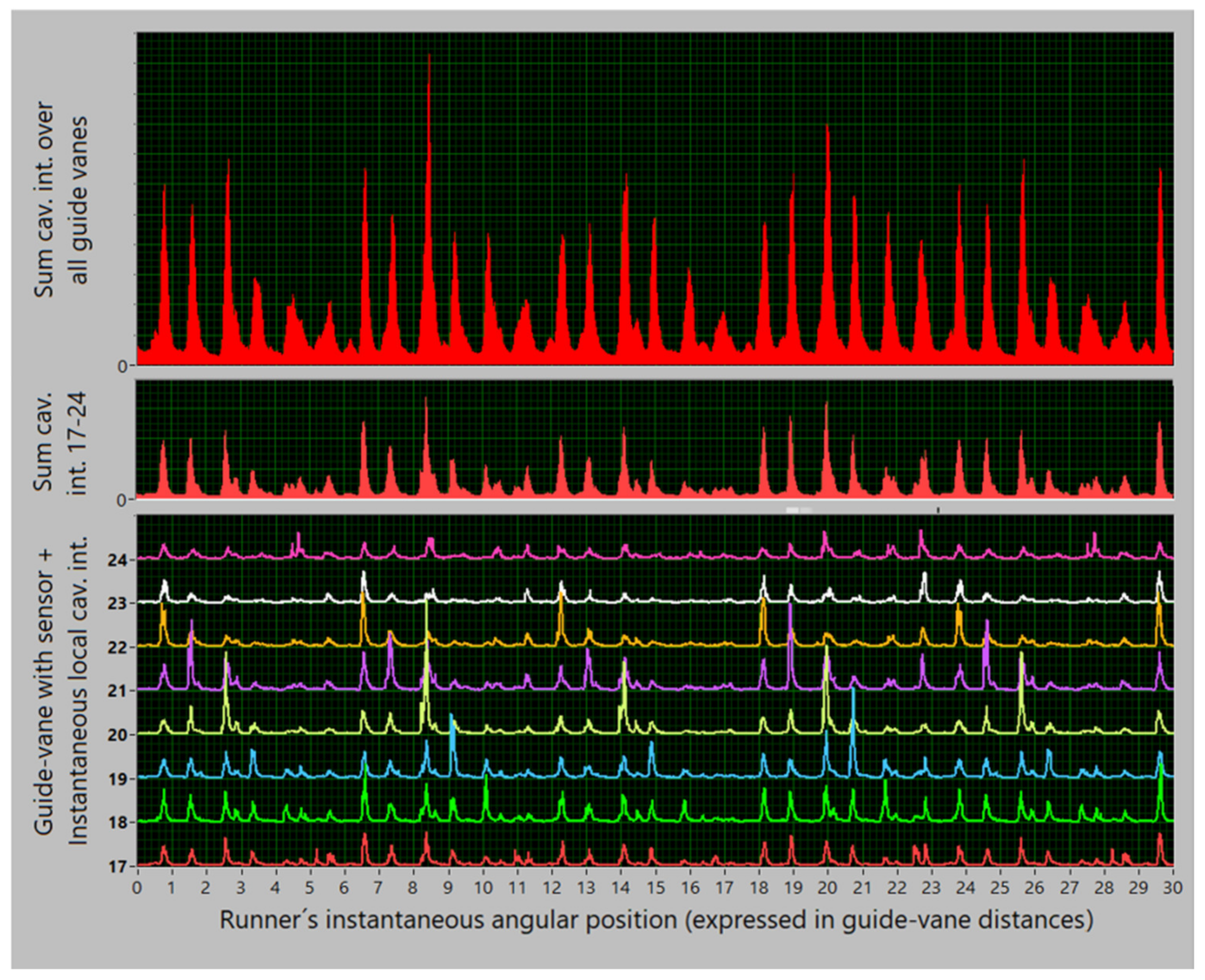
Figure A2—The graph at the top stays the same in all the Figure A1, Figure A2, Figure A3, Figure A4 and Figure A5; it represents the stationary mechanism, sta(,Φ). The graph at the bottom shows here Ir(,Θv,Φ) and not I(,Θv,Φ) as in Figure A1; both these functions are drawn for v = 17–24. The middle graph is also now filled with the data on the rotating mechanism, i.e., with the temporal dependence of the total intensity of the rotating mechanism at a given operation point, rot(,Φ). Comparing now the middle graphs in Figure A1 and Figure A2, an essential difference can be observed. The graph in Figure A1 is derived as a segment of sta(,Φ) on the eight selected guide vanes, and the graph in Figure A2 shows rot(,Φ) on the same guide vanes. While this segment of sta(,Φ) follows the form of the full sta(,Φ) of the graph at the top of Figure A1, rot(,Φ) in the middle graph in Figure A2 has a new form. Due to shifts that transform I(,Θ,Φ) into Ir(,Θ,Φ) as in (6), the true traces of the rotating mechanism are now concentrated in the same narrow intervals of Φ.
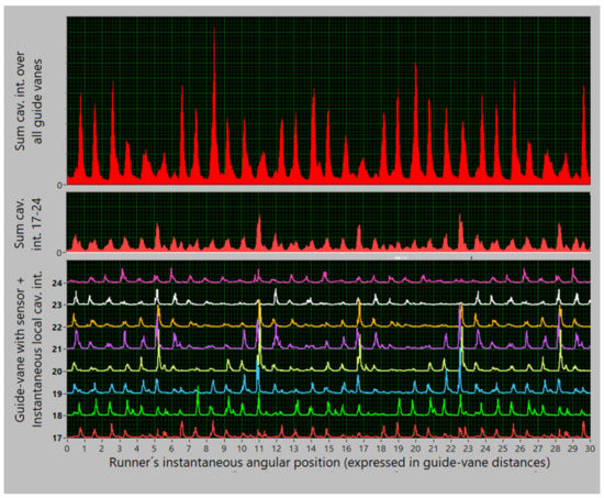
Figure A2.
From above: sta(,Φ) estimated by all v’s; rot(,Φ) estimated by v = 17–24; and Ir(,Θv,Φ) for v = 17–24; everything for a single , drawn above Φ.
Figure A2.
From above: sta(,Φ) estimated by all v’s; rot(,Φ) estimated by v = 17–24; and Ir(,Θv,Φ) for v = 17–24; everything for a single , drawn above Φ.
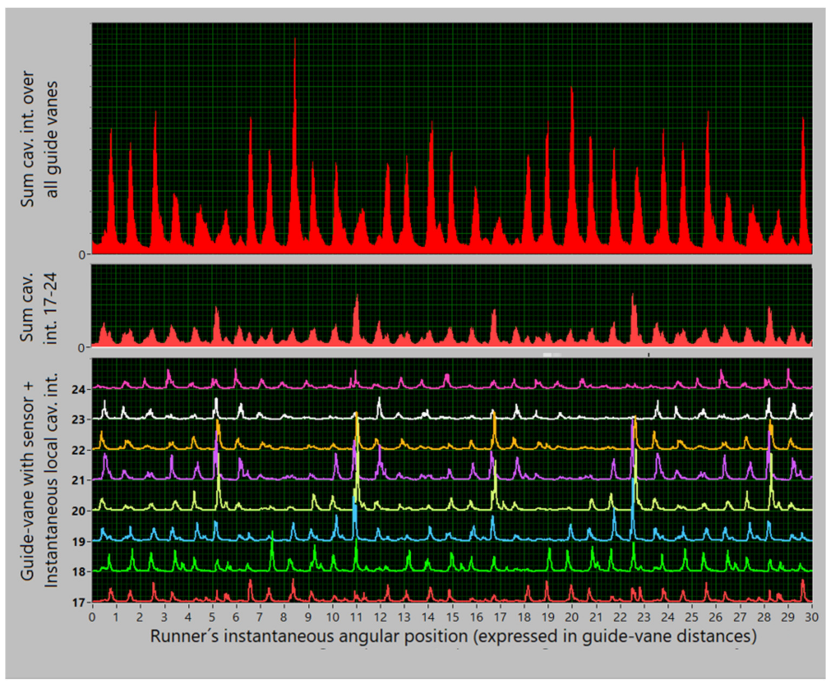
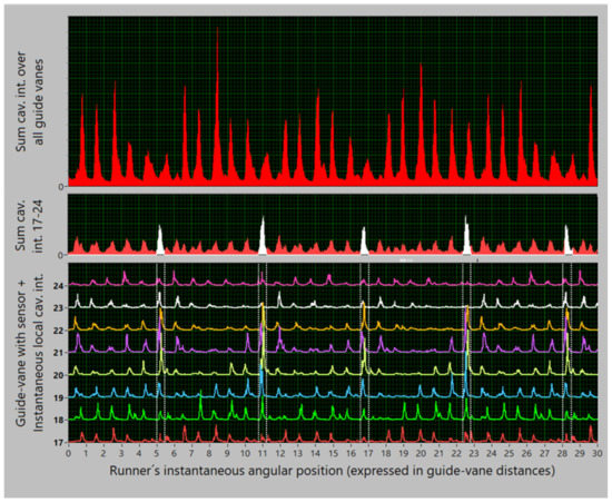
Figure A3.
All as in Figure A2 but with denoted limits of filtering in Φ for extracting the rotating mechanism. Note that some further peaks in the vicinity of the filtered range might also be included.
Figure A3.
All as in Figure A2 but with denoted limits of filtering in Φ for extracting the rotating mechanism. Note that some further peaks in the vicinity of the filtered range might also be included.
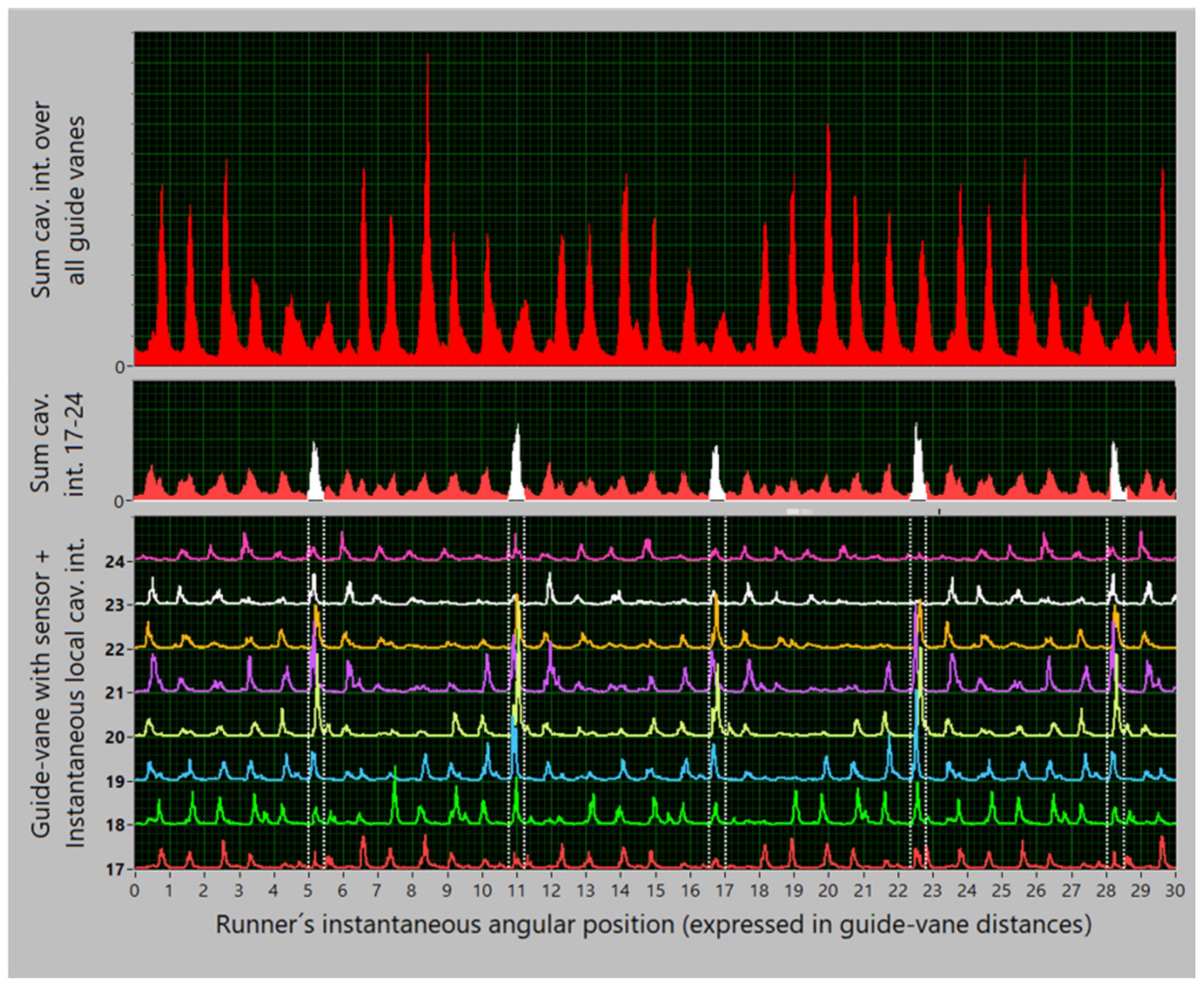
Figure A3—The concentration of data segments which represent the rotating mechanism is clearly seen in this figure. There are one-guide-vane-wide white segments that surely belong to the rotating mechanism and are well defined in the temporal dimension, Φ. However, on some guide vanes, e.g., 20, 21, and 22, some neighbouring peaks might also be assigned to this mechanism.
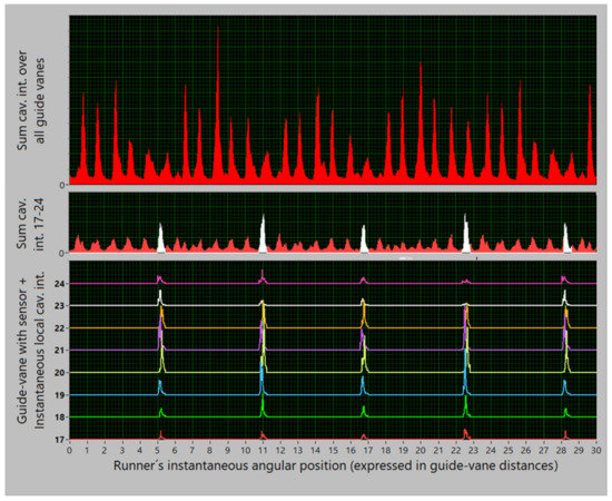
Figure A4.
All as in Figure A3 but with extracted segments which surely belong to the rotating mechanism. Four peaks with Φ within a revolution (0–24), describe the four runner blades.
Figure A4.
All as in Figure A3 but with extracted segments which surely belong to the rotating mechanism. Four peaks with Φ within a revolution (0–24), describe the four runner blades.
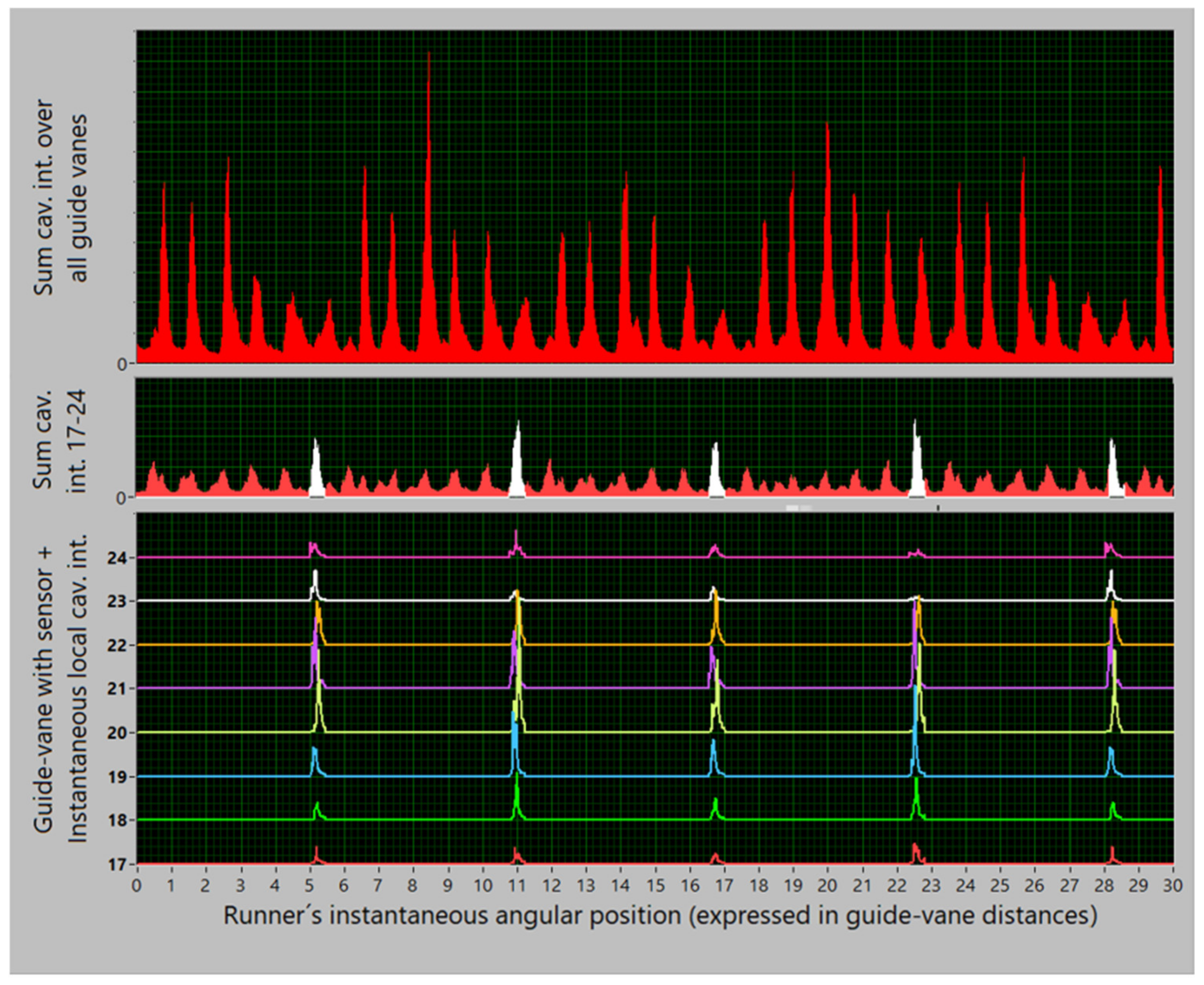
Figure A4—Indeed, by the noted temporal filtering, the clean data segments belonging to the rotating mechanism are obtained. Their mean traces in the middle graph differ from the surroundings, which are mostly the traces of the stationary mechanism, defocused by filtering the rotating mechanism. Still, both traces, from the rotating mechanism (the white ones and some neighbouring peaks) and from the stationary mechanism (red), are present in the middle graph. Therefore, at a given operation point, both rotating and stationary mechanisms occur.
Figure A5—Now, preserving the components due to the rotating mechanism, obtained by temporal filtering, and turning back the process of shifting, i.e., returning Ir(,Θ,Φ) into the format of I(,Θ,Φ), an interesting pair of curves is obtained – the true original I(,Θ,Φ) in the graph at the bottom of Figure A1 showing the total cavitation, and such a function incorporating only the principal components of the rotating mechanism in the graph at the bottom of Figure A5.
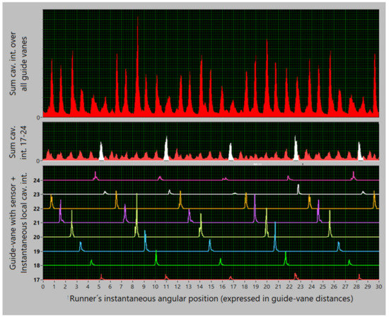
Figure A5.
All as in Figure A4, with the extracted rotating mechanism turned back in the big graph into the format of Figure A1, thus with I(,Θv,Φ) with the rotating mechanism only.
The analysis described above is made on a segment of data at one single operation point, with a rather low load. The analyses performed at many other operation points have shown that, on guide vanes 19–22, the rotating mechanism prevails at higher loads and that the described filtering proves to be too narrow there. In general, the separation of the two mechanisms, the stationary and the rotating one, as found in Figure 15, is a suitable first approximation: there is a circumferential segment, i.e., a group of guide vanes that should be predominantly attributed to the rotating mechanism and the rest belongs to the stationary mechanism. Moreover, as the first approximation of the stationary mechanism in terms of the mean global cavitation intensity, the values derived from all the guide vanes are used. Of course, both estimates – the one meant for the rotating mechanism and looked for in guide vanes 19–22 or 17–24, and another meant for the stationary mechanism and looked for in all the guide vanes – are biased, and in both the nominal mechanism is overestimated.
Figure A1, Figure A2, Figure A3, Figure A4 and Figure A5 bring the temporal, i.e., Φ-dependence of the drawn cavitation components. The next step of the analysis compresses these data into the temporal averages, <●>Φ. This step is performed by following the logic of distinguishing between the two mechanisms described above, which means that the estimates sta() and rot() are derived as in (13) from the data on sta(,Φ) and rot(,Φ) drawn in the upper two graphs in Figure A2. For all the available power values, the result is shown in Figure A6. This is the best estimate of the two mechanisms that can be simply derived from the measurement by the sensors on the guide vanes.
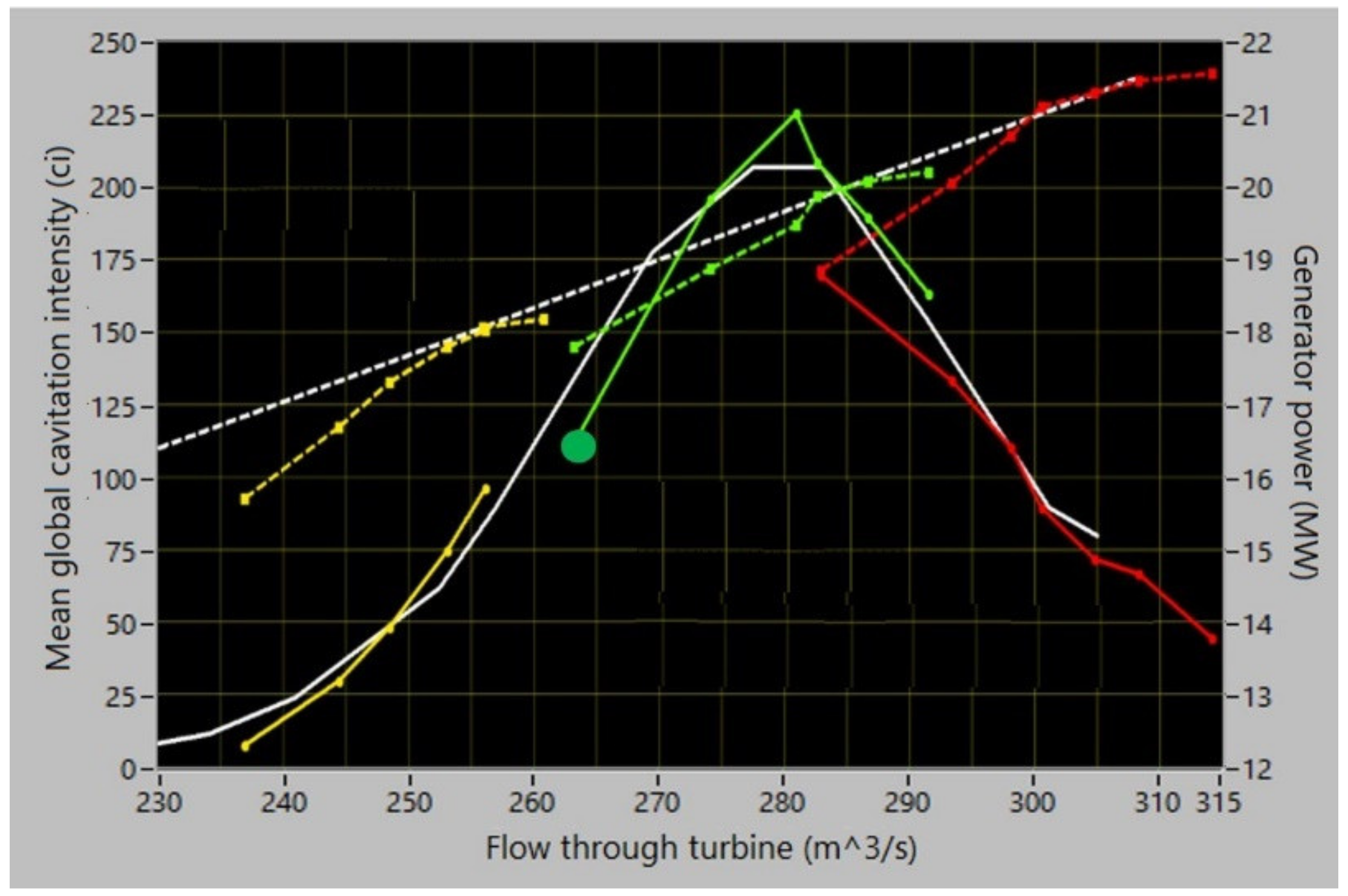
Figure A7 brings a crucial new element in the reasoning. In it, the two simple direct measurements of the mean global cavitation intensity, I() by means of the sensors on the guide vanes and J() by means of the sensor on the turbine shaft, are confronted with the results of the identification and estimation of the two cavitation mechanisms derived above on pure data acquired by the sensors on the guide vanes. The conclusion is evident: the sensor on the turbine shaft (white curve), which senses all cavitation segments close to the turbine runner by almost equal sensitivity, detects both the stationary cavitation mechanism (red dots) and the rotating cavitation mechanism (white dots), while the sensors on the guide vanes (red curve) only estimate the true cavitation intensity of the stationary cavitation mechanism (red dots). The sensors on the guide vanes also detect the rotating mechanism, clearly enough to be useful in its detection but not well enough to correctly assess its intensity. Unfortunately, it is not possible to use the sensor on the turbine shaft to distinguish between the two mechanisms in the way presented above. The cause of the difference in the functioning of the sensors lies in the turbine geometry (Figure A8). Note that the white curve and the white dots in Figure A7 do not fit each other fully. A possible reason is noted in the figure: the curve is a true global mean, but the dots describe only one of the four runner blades.
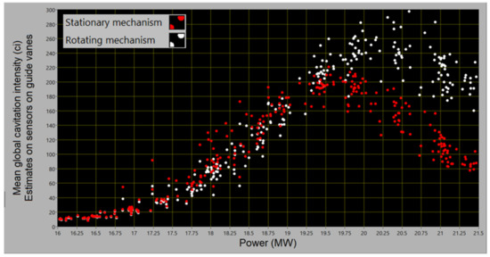
Figure A6.
The two mechanisms estimated based on the data from the sensors on the guide vanes. Stationary mechanism: sta() with all guide vanes included; Rotating mechanism: rot() with guide vanes 17–24 included.
Figure A6.
The two mechanisms estimated based on the data from the sensors on the guide vanes. Stationary mechanism: sta() with all guide vanes included; Rotating mechanism: rot() with guide vanes 17–24 included.
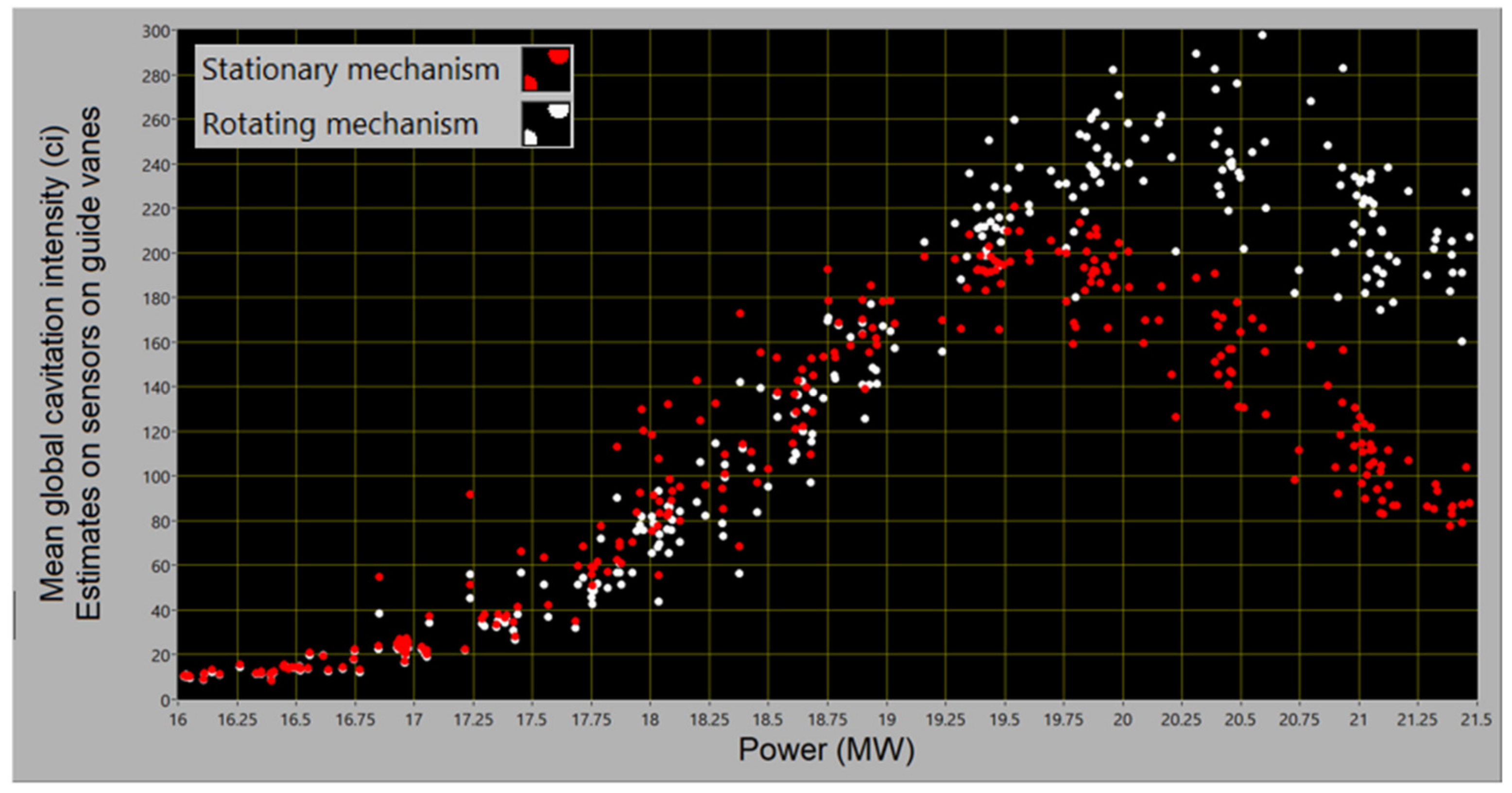
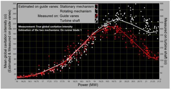
Figure A7.
Estimates (dots): as in Figure A6. Measurement (curves): I() (left scale) J() (right scale) c = I(o)/J(o) set to 0.5 to overlap the curves at Oo ≤ 19 MW.
Figure A7.
Estimates (dots): as in Figure A6. Measurement (curves): I() (left scale) J() (right scale) c = I(o)/J(o) set to 0.5 to overlap the curves at Oo ≤ 19 MW.
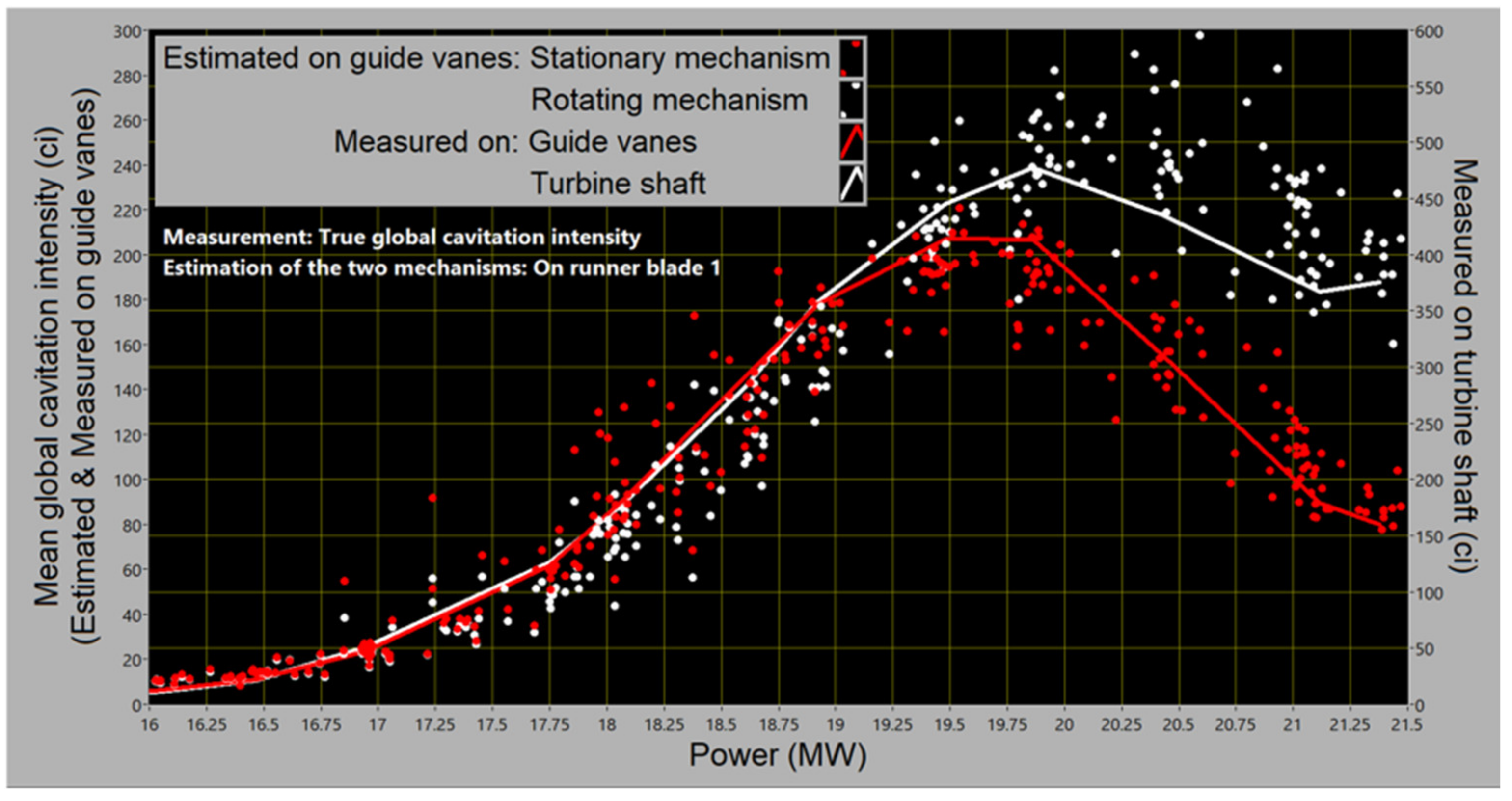
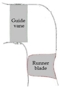
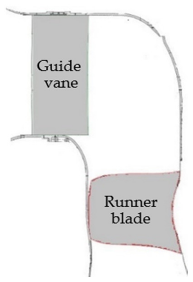
Figure A8.
Guide vanes as the antennas for the hydro-acoustic waves stemming from the cavitation on the runner function differently for cavitation in different locations. The reception for the blade-surface cavitation might be fully or partially blocked by the shadow of the runner blade’s body at some angular settings of the runner, i.e., at some loads. The reception is clearer for the waves coming from the cavitation on the blade’s edge, thus also for the tip cavitation.
Final conclusions:
- the sensor on the guide vanes may be used to clarify cavitation details but the sensor on the turbine shaft should be used to estimate the cavitation intensity, the total one and the intensities of the two mechanisms;
- the surface cavitation mechanism is sensed fully by the rotating sensor and not so well by the stationary sensors; therefore, the surface mechanism is the one which rotates with the runner;
- the intensities of both cavitation mechanisms may be safely calibrated according to (15), thus in a way to make the sum of their mean values equal to the mean global intensity measured by the sensor on the shaft; the scale calibration is irrelevant here (that of the guide vanes is adopted in the figures, with suitable value for c found to be 0.5);
- consequently, the data for the rotating mechanism, i.e., surface cavitation should be approximately estimated by the difference between the data measured by the sensor on the turbine shaft and the data obtained by the sensors on the guide vanes.
All this leads to the data on the two mechanisms as shown in Figure 17. The intensity estimates of the mechanisms are somewhat biased. Both are overestimated: that of the surface cavitation close to its threshold, and that of the tip cavitation at the highest turbine loads.
As for the circumferential distribution of the mechanisms, the result in Figure 18 and Figure 19 follows from the Φ-averaged data over the eight selected guide vanes in the graph at the bottom of Figure A4 for the rotating/surface mechanism, and from the Φ-averaged data over all the guide vanes in Figure 12b for the stationary/tip mechanism. The data are normalised to the total 100% separately for each mechanism. The data for the tip mechanism are slightly overestimated, and those for the surface mechanism somewhat underestimated, especially on the guide vanes where they reach the maximum.
The estimates of the size of the cavitation erosion patches in Figure 20 follow from the data in Figure A9. The physics behind this is simple: both erosion and noise emitted by the cavitation are strongest in the moments and places when and where cavitation voids disappear. This makes it possible to trace the erosion by locating strong acoustical noise. Zero length is marked by the noise just above the cavitation threshold, and the end at a given operation by the shift of the strong noise found at that operation. Since no erosion will probably occur from weak cavitation, this way of measuring describes more the size of the cavitation than of the erosion patch.
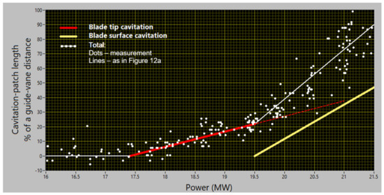
Figure A9.
Origin of the lines in Figure 20. The straight-line model for the total cavitation follows the trends of the measured data for the shift of cavitation peaks with the increasing load; they were already noted in Figure 12a. The zero points of the red and yellow lines roughly coincide with the thresholds of the two cavitation mechanisms as in Figure 17; this is how they become attributed to the two mechanisms. While the solid red line here simply follows the dots, the yellow line is heuristically estimated by the difference between the total trend and the extrapolated trend of the low power, i.e., tip mechanism.
Appendix 2. Suitable Input Circuitry
The high number of sensors required in the multidimensional method makes it necessary to optimise the input circuitry with respect to the price. Here is one such configuration; it was successfully applied on different turbines.
Highest-resonant-frequency piezo-accelerometers are used without preamplifiers; this lowers the costs, avoids limitation in amplitude dynamics, and makes power-supply connections unnecessary.
The following simple input circuitry has proven to be acceptable. The accelerometers are connected via 10–20 m of a 100 pF/m coaxial cables directly to the voltage input of a multi-channel simultaneous-sampling broadband ±10 V 16-bit ADC with a very fast sample-and-hold element. In such a combination, the accelerometers with own capacity below 1 nF and a charge sensitivity of 1–2 pC/g sense the broadband non-cavitation background noise and thus keep cavitation signals also well represented. The cables are kept equally long and the sensitivity of the channels are assessed from the individual sensitivities of the accelerometers.
Resistors should be connected in parallel to the inputs to stabilise the DC drift in the capacitive circuitry and form simple high passes. Their resistance, of the order of 1 MΩ, should be selected for a limit frequency of this filter, typically of the order of 1–3 kHz, required to suppress the background noise. Acting below the important cavitation spectrum range, this filter will not distort the basic signal processing.
An alternative to this scheme with accelerometers, is one with acoustic emission sensors.
Appendix 3. On Cavitation-Generated Vibration
In the off-cam and the high-head/high-flow on-cam operation of the prototype, considerable axial vibration was measured on the turbine bearing of the considered turbine. Interestingly,
(A) radial vibration was negligible.
While the spectrum lines on the two lowest resonant frequencies of the turbine structure, 32.5 Hz and 52.5 Hz, were expected to appear in the vibration spectrum,
(B) a rather dense broadband line spectrum was found.
In what follows, it is shown that cavitation as a cause of vibration can explain the peculiarities (A) and (B) of the vibration process.
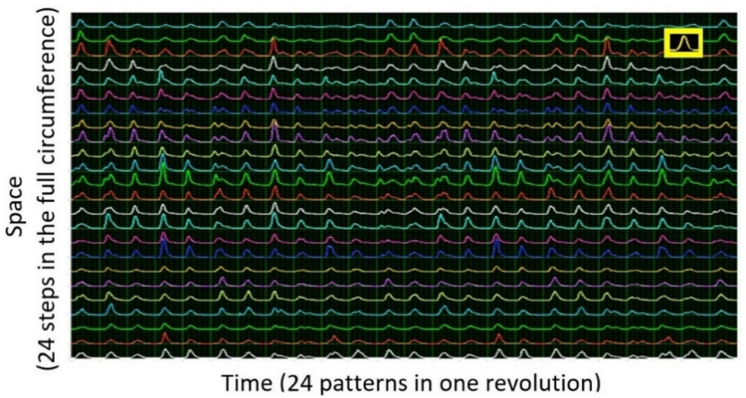
The idea of cavitation as the cause of vibration is best presented by the data in Figure 14. The 24 × 24 local patterns in the figure are similar, and the 24 rows are synchronised with each other. The sum of the rows estimates the instantaneous total cavitation intensity in the turbine. It consists of 24 times amplified, almost periodically distributed 24 local patterns of the form illustrated in the yellow rectangle in the figure. This total cavitation-intensity waveform describes the repeated process of setting the cavitation on and off as caused by the interaction of the runner with the wakes behind the guide vanes. Such a dynamic process causes repeated variations of the pressure field in the vicinity of the runner blades. The turbine structure strongly reacts to this dynamic excitation by the vibration on the resonant frequencies and on those excitation frequencies which are not far from the resonant frequencies. This process is simply modelled as follows.
The instantaneous total cavitation intensity, , as a function of the time t can be approximately modelled by
where (=24) is the number of guide vanes; the first sum goes over space, the second sum over time; is the typical local cavitation-intensity pattern; T (60/75 s) is the revolution period which corresponds to the guide-vane passage frequency of 30 Hz. Using
as the model of a single pattern shown in the yellow rectangle in Figure 14, we obtain for the module of the n-th coefficient of the complex Fourier series of over the period [0, T]:
where = = (/T) is the discrete form of the amplitude spectrum (f) of f being the frequency variable.
Modelling the turbine structure by a simple one-degree-of-freedom vibration system, and taking heuristically (f) for the excitation spectrum, we obtain for the vibration spectrum
where:
is the system’s transfer function with and being the system’s resonant frequency and damping ratio, respectively ( = 1 corresponds to the limit of the oscillatory response).
The model presented above yields the result as in Figure A10a. The strong excitation by cavitation, amplified by the contribution from spatial points and with cavitation events repeated times per revolution, gives rise to a very strong line on the guide-vane passage frequency (n = = 24, f = 30 Hz); there is a trace on its first harmonic, too.
The resonance (32.5 Hz, n = 26) is only peripherally propagated through the model; it is present via its side-lines in the cavitation-intensity spectrum. In reality, the mechanical and non-cavitation hydraulic sources of instability might excite stronger vibration on the resonance. The above model and the results in Figure A10 describe only the cavitation contribution to the vibration; there might also be other sources.
Figure A10b illustrates the generation of further spectrum lines due to cavitation. The new lines—the dominant one on the guide-vane passage frequency and several others—explain the peculiarity (B) of the vibration process mentioned above. The peculiarity (A) in turn is a direct consequence of the uniform circumferential distribution of the cavitation intensity.
Figure 12b and Figure 14 illustrate the variability of the space-time distribution of cavitation events. Some extreme cases of this distribution are listed in Table A1. The vibration they cause is briefly characterised in a way following the above analysis. V is the number of guide vanes, B is the number of runner blades.
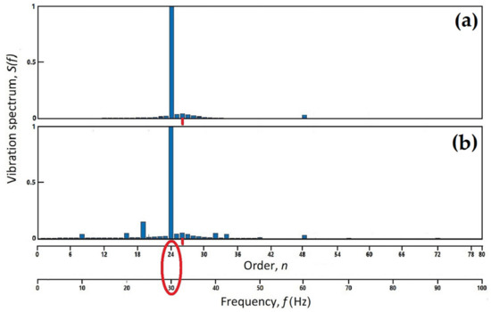
Figure A10.
Idea of the spectrum of the vibration component caused by the cavitation: (a) cavitation as in Figure 14 but with all local patterns equal; (b) cavitation with a slightly disturbed set of the local patterns. Only the resonance at 32.5 Hz is considered, the damping ratio 0.05 is assumed; the amplitude scale is arbitrary.

Table A1.
Vibration data in four extreme cases.
Table A1.
Vibration data in four extreme cases.
| Number of guide vanes causing cavitation Number of runner blades with cavitation | 1 1 | 1 All | All 1 | All All |
| Number of cavitation events per revolution in the total intensity Vibration amplitude is proportional to thus, for V = 24, B = 4, to Basic vibration frequency = revolution frequency multiplied by thus, for V = 24, B = 4, by | 1 1 1 1 1 | B B 4 B 4 | V V 24 V 24 | V V2 576 V 24 |
The danger introduced by the All/All-case and other rich configurations of cavitation events, such as in Figure 14, is evident: on a high frequency, which is close to the resonance, they generate a very high vibration amplitude.
References
- Rayleigh, L. On the pressure developed in the liquid during the collapse of a spherical cavity. Lond. Edinb. Dublin Philos. Mag. J. Sci. 1917, 34, 94–98. [Google Scholar] [CrossRef]
- Brennen, C.E. Cavitation and Bubble Dynamics; Oxford Press: Oxford, UK, 1995. [Google Scholar]
- Pearsall, I.S. Acoustic detection of cavitation. In Proceedings of the Symposium on Vibrations in Hydraulic Pumps and Turbines, Manchester, England, 14–16 September 1966; Volume 181, pp. 1–8. [Google Scholar]
- Varga, J.J.; Sebestyen, G.; Fay, A. Detection of cavitation by acoustic and vibration-measurement methods. La Houille Blanche 1969, 24, 137–149. [Google Scholar] [CrossRef] [Green Version]
- Abbot, P.A.; Gedney, C.J.; Greeley, D.L. Cavitation monitoring of two axial-flow-hydroturbines using novel acoustic and vibration methods. In Proceedings of the 13th IAHR Symposium, Montreal, QC, Canada, 2–5 September 1986; Volume 1. Paper 23. [Google Scholar]
- Abbot, P.A. Cavitation detection measurements on Francis and Kaplan hydroturbines. In Proceedings of the International Symposium on Cavitation Noise and Erosion in Fluid Systems, ASME, New York, NY, USA, 10–15 December 1989; FED-88. pp. 55–61. [Google Scholar]
- Bourdon, P.; Simoneau, R.; Lavagne, P. A vibratory approach to the detection of erosive cavitation. In Proceedings of the International Symposium on Cavitation Noise and Erosion in Fluid Systems, San Francisco, CA, USA, 10–15 December 1989; FED-Vol. 88. pp. 103–109. [Google Scholar]
- Bajic, B.; Keller, A. Spectrum normalization method in vibroacoustical diagnostic measurements of hydroturbine cavitation. J. Fluids Eng. 1996, 118, 756–761. [Google Scholar] [CrossRef]
- Farhat, M.; Bourdon, P.; Lavigne, P. Some Hydro Quebec experiences on the vibratory approach for cavitation monitoring. In Proceedings of the Conference Modelling, Testing & Monitoring for Hydro Powerplants, Lausanne, Switzerland, 8–11 July 1996; pp. 151–161. [Google Scholar]
- Bajic, B. Vibroacoustical diagnosis of hydroturbine cavitation: Some measurement and analysis methods. In Proceedings of the Conference Modelling, Testing & Monitoring for Hydro Powerplants, Lausanne, Switzerland, 8–11 July 1996; pp. 169–178. [Google Scholar]
- Bajic, B. Inflow decomposition: A vibroacoustical technique to reveal details of hydroturbine cavitation. In Proceedings of the Conference Hydropower into the Next Century, Portoroz, Slovenia, 15–17 September 1997; pp. 185–196. [Google Scholar]
- Bajic, B. Multidimensional diagnostics of turbine cavitation. J. Fluids Eng. 2002, 124, 943–950. [Google Scholar] [CrossRef]
- Escaler, X.; Egusquiza, E.; Mebarki, T.; Avellan, F.; Farhat, M. Field assessment of cavitation detection methods in hydropower plants. In Proceedings of the 21st IAHR Symposium on Hydraulic Machinery and Systems, Lausanne, Switzerland, 9–12 September 2002. [Google Scholar]
- Bajic, B. Multidimensional monitors for hydroelectric power plants. In Proceedings of the Hydro 2002 Conference, Kiris, Turkey, 4–7 November 2002. [Google Scholar]
- Bajic, B. Methods for vibroacoustic diagnostic of turbine cavitation. J. Hydraul. Res. 2003, 41, 87–96. [Google Scholar] [CrossRef]
- Escaler, X.; Egusquiza, E.; Farhat, M.; Avellan, F. Vibration cavitation detection using onboard measurements. In Proceedings of the Fifth International Symposium on Cavitation, Osaka, Japan, 1–4 November 2003. [Google Scholar]
- Escaler, X.; Egusquiza, E.; Farhat, M.; Avellan, F. Cavitation erosion prediction in hydro turbines from onboard vibrations. In Proceedings of the 22nd IAHR Symposium on Hydraulic Machinery and Systems, Stockholm, Sweden, 29 June–2 July 2004. [Google Scholar]
- Escaler, X.; Egusquiza, E.; Farhat, M.; Avellan, F.; Coussirat, M. Detection of cavitation in hydraulic turbines. Mech. Syst. Signal Process. 2006, 20, 983–1007. [Google Scholar] [CrossRef] [Green Version]
- Pastushenko, V. Kavitation in Wasserturbinen—Entwicklung eines Monitoringsystems. Ph.D. Thesis, Munich Technical University, München, Germany, 2006. [Google Scholar]
- Bajic, B. Grand Coulee G-20 Multidimensional Cavitation Test - Comparison of Three Cavitation Monitoring Techniques; Report Korto GC082103, 2008, Volume 1. Available online: http://www.korto.com/downloads/reports/Korto_Grand_Coulee_G-20_Cavitation_Report_Korto_GC082103-Vol_1.pdf (accessed on 13 February 2022).
- Bajic, B. Grand Coulee G-20 Multidimensional Cavitation Test - Comparison of Three Cavitation Monitoring Techniques; Report Korto GC082103, 2008, Volume 2. Available online: http://www.korto.com/downloads/reports/Korto_Grand_Coulee_G-20_Cavitation_Report_Korto_GC082103-Vol_2.pdf (accessed on 13 February 2022).
- Bajic, B. Multidimensional and simple techniques for cavitation diagnostics and monitoring. Powertec Russ. CIS, 21 September 2010; 50–63. Available online: https://issuu.com/rogtecmagazine/docs/powertec_issue2_lowres(accessed on 13 February 2022).
- Schmidt, H.; Kirschner, O.; Riedelbauch, S.; Necker, J.; Kopf, E.; Rieg, M.; Arantes, G.; Wessiak, M.; Mayrhuber, J. Influence of the vibroacoustic sensor position on cavitation detection in a Kaplan turbine. In Proceedings of the 27th IAHR Symposium on Hydraulic Machinery and Systems, Montreal, Canada, 22–26 September 2014; IOP Conf. Series: Earth and Environmental Science. 2014; Volume 22, p. 052006. [Google Scholar]
- Germann, J. Cavitation Detection Technology for Optimizing Hydraulic Turbine Operation and Maintenance. U.S. Bureau of Reclamation Report ST-2015-2944-01. 2017. Available online: https://www.usbr.gov/research/projects/detail.cfm?id=2944 (accessed on 13 February 2022).
- Valentin, D.; Presas, A.; Egusquiza, M.; Valero, C.; Egusquiza, E. Transmission of high frequency vibrations in rotating systems. Application to cavitation detection in hydraulic turbines. Appl. Sci. 2018, 8, 451. [Google Scholar] [CrossRef] [Green Version]
- Valentin, D.; Presas, A.; Valero, C.; Egusquiza, M.; Egusquiza, E. Detection of hydraulic phenomena in Francis turbines with different sensors. Sensors 2019, 19, 4053. [Google Scholar] [CrossRef] [PubMed] [Green Version]
- Presas, A.; Luo, Y.; Valentin, D.; Egusquiza, M.; Wang, Z.; Valero, C.; Egusquiza, E. Detection of erosive cavitation on hydraulic turbines through demodulation analysis. In IOP Conference Series: Earth and Environmental Science; IOP Publishing: Bristol, UK, 2019; Volume 240, p. 062048. Available online: https://iopscience.iop.org/article/10.1088/1755-1315/240/6/062048 (accessed on 13 February 2022).
- Mortensen, J. Cavitation Detection—Method Development to Detect Damaging Cavitation. U.S. Bureau of Reclamation Report ST-2017-1708-01. 2017. Available online: https://usbr.gov/tsc/techreferences/hydraulics_lab/pubs/HL/HL-2017-10.pdf (accessed on 13 February 2022).
- Luo, X.-W.; Ji, B.; Tsujimoto, Y. A review of cavitation in hydraulic machinery. J. Hydrodyn. 2016, 28, 335–358. [Google Scholar] [CrossRef]
- Jones, R.K.; March, P.A. Application of Acoustic Emissions for Real-Time Monitoring of Cavitation; Report No. WR28-4-900-234; Tennessee Valley Authority: Norris, TN, USA, 1989. [Google Scholar]
- Derakhshan, O.; Houghton, J.R.; Jones, R.K.; March, P.A. Cavitation Monitoring of Hydroturbines with True-RMS Acoustic Emission Measurement; ASTM Special Publication 1077; American Society for Testing and Materials: Philadelphia, PA, USA, 1990. [Google Scholar]
- Wolff, P.J.; Jones, R.K.; March, P. Evaluation of Results from Acoustic Emissions-Based Cavitation Monitor, Grand Coulee Unit G-24: Cavitation Monitoring System Comparison Tests; Grand Coulee Project Final Report; WolffWare Ltd.: Noriss, TN, USA, 2005; Available online: http://www.wolffwareltd.com/downloads/Grand%20Coulee%20Cavitation%20Report.pdf (accessed on 13 February 2022).
Publisher’s Note: MDPI stays neutral with regard to jurisdictional claims in published maps and institutional affiliations. |
© 2022 by the authors. Licensee MDPI, Basel, Switzerland. This article is an open access article distributed under the terms and conditions of the Creative Commons Attribution (CC BY) license (https://creativecommons.org/licenses/by/4.0/).

