1. Introduction
Throughout a typical petroleum reservoir’s productive life, natural lift force due to fluid pressure tends to decay and diminish. Therefore, artificial lift methods are commonly utilized to transfer the oil and gas from the formation to the surface. The most popular artificial lift means are the sucker rod pumping system, hydraulic pumping system, electric submersible pumping system, and gas lift system [
1,
2]. As one of the earliest inventions for oil fields in land, the sucker rod pumping system has proved to be one of the most efficient and popular artificial lift systems in the petroleum industry [
2,
3,
4].
In references [
5,
6], the largest relaxation times have been estimated and compared based on transient solutions with Bessel functions for cylindrical coordinates and Fourier series for Cartesian coordinates. It is confirmed that the largest relaxation times are still less than a tenth of the typical sampling period used in oil industries with comparable physical dimensions. The resulting steady analytical solutions have also been compared with full-fledged transient computational fluid dynamics (CFD) solutions. The sampling rate adopted in oil fields normally ranges from 30 to 60 samples per second. Thus, the quasi-static nature of the flow within annulus regions in typical sucker rod pump systems has been confirmed with both analytical and computational studies. The full-fledged computational fluid dynamics results have also been documented in references [
5,
6] with a well-established commercial code ADINA for the annulus region using measured pressure differential and plunger velocity as boundary conditions. These sets of computations have yielded nearly identical flow rates through the annulus region directly matching with the analytical formulas for quasi-static Poiseuille and Couette viscous flows respectively as documented in references [
5,
6]. Finally, the effects of the eccentricity have been established analytically with the perturbation method and have been directly verified with the flow rates passing through the annulus region with various eccentricities calculated with the full-fledged computational fluid dynamics. As documented in reference [
6], the flow rate is related to the eccentricity and follows the same quadratic relationship with the eccentricity as analytically predicted with the perturbation method.
In this paper, we focus more on the production efficiency with respect to the pump mechanisms, which consists of a moving contact area between the traveling unit (plunger), a chamber with a so-called traveling valve, and the tube or barrel with a so-called standing valve [
7]. We have substituted the complicated downhole pump unit with a simple viscoelastic model such as a Kelvin or Maxwell viscoelastic model and confirmed the similar relationship between the polished rod load and the displacement measured in experiments and operations.
Very often a clearance between 3 to 8 mills (one thousandth of an inch) is recommended to avoid the direct contact (abrasion) between the plunger and the tube and to allow the unimpeded passage of sands and particles within the oil mixture [
8,
9]. In practice, it has been reported that the leakage is related to the clearance, or two times the gap size, defined as the difference between the inner diameter of the barrel and the outer diameter of the plunger [
10,
11]. In the existing literature, it has been established that for viscous fluid to squeeze through a narrow annulus channel, the required pressure gradient or pressure drop given a fixed channel length will be proportional to the clearance to the power of three [
7,
12,
13]. Moreover, analytical approaches were presented in the study of both leakage and eccentricity effects which have also been confirmed by comparable computational fluid dynamics and experimental data with similar quasi-static responses [
6]. In this paper, based on the information we have obtained in our study of leakage issues and effects of the eccentricity [
5,
6], namely, the viscous force acting on the plunger is proportional to the pressure drop for the Poiseuille flow and the plunger velocity for the Couette flow. Moreover, for the Poiseuille flow, volume flow rate or the leakage is proportional to the pressure drop and for the Couette flow, the volume flow rate is proportional to the plunger velocity. Thus, in this paper we have attempted to replace the entire downhole sucker rod pump system with a simple viscoelastic model to mimic sucker rod pump units behavior, in particular the piston-like motions between the plunger and the barrel.
2. Theory and Experimental Setup
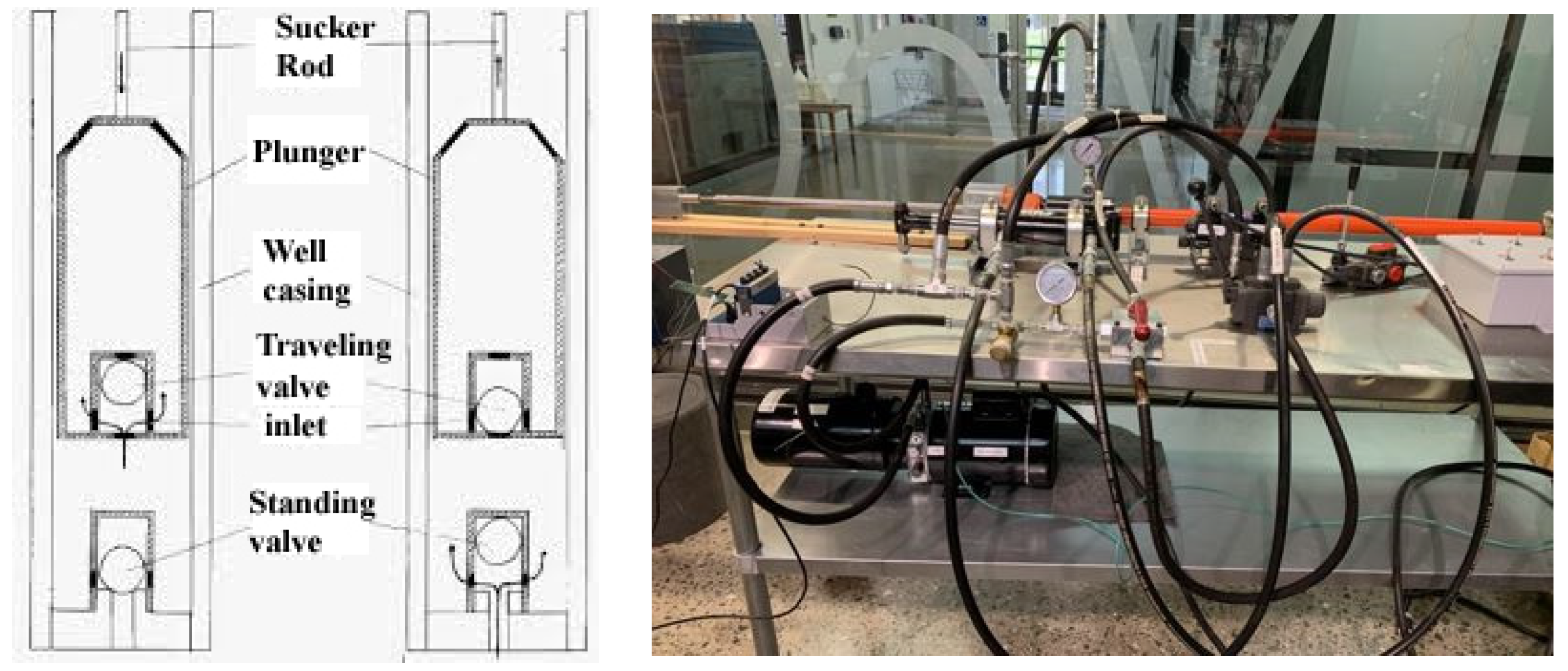
In the sucker rod experimental setup with horizontal configuration established in McCoy Engineering Hall at Midwestern State University, a member of the Texas Tech University System, as shown in
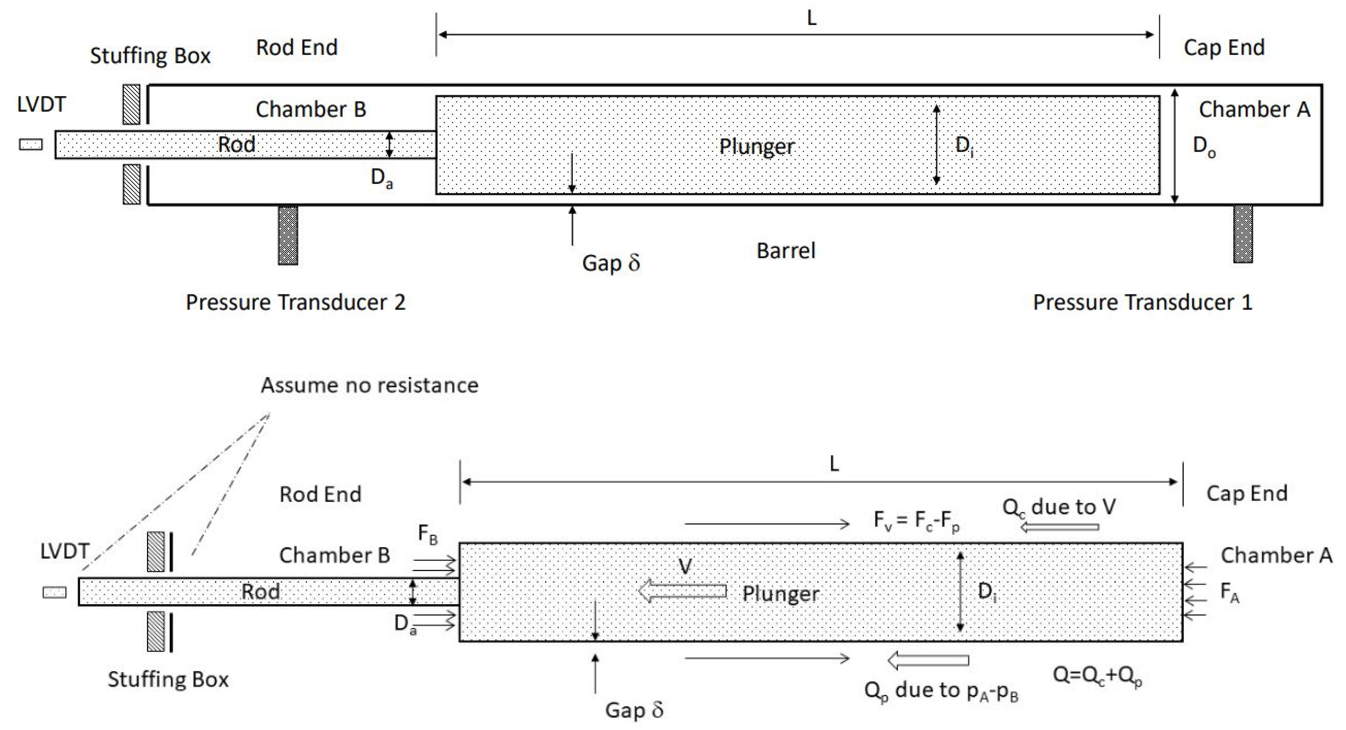
Figure 1, we used one solenoid valve with four ports and three positions. The physical and mathematical model is depicted in
Figure 2. Chamber A near the cap end corresponds to the sucker rod pump stationary valve unit, the plunger with a length L is the exactly same plunger used in industry. Chamber B near the rod end represents the oil well section above the sucker rod pump, more precisely, the traveling valve unit. To ensure the air and liquid tightness, we use the same stuffing box to support the retracting sucker rod physically attached to the plunger as implemented in the oil field. Moreover, a position measurement system linear variable displacement transducer (LVDT) is installed at the tip of the sucker rod. Transient pressure within both chambers A and B will be measured with a sampling rate of 30 samples per second or 30 Hz using the Echometer pressure measurement system following the confirmation of theoretical and computational studies in references [
5,
6] as well as engineering practice in oil fields.
As illustrated in
Figure 2, consider the plunger with an outer diameter D
i and the barrel inner diameter D
o. Note that the subscript o and i are designated with respect to the annulus flow region boundaries, namely, the outer region is the barrel inner surface and the inner region is the plunger outer side. Assume the gap δ denoted as
is small in comparison with D
o and D
i. In engineering practice, the clearance C is equivalent to 2δ with ε =
.
The external horizontal forces acting on the plunger are depicted in
Figure 2 which include the viscous force F
p due to the pressure differential and the viscous force F
c due to the plunger motion as well as the normal forces F
A and F
B due to the pressure in chambers A and B, respectively. Assume the atmospheric pressure p
atm and the plunger is moving at this time instant with a velocity V to the left, a positive direction in this case, we have viscous shear force F
p acting on plunger to the right in the same direction as the pressure difference or the Poiseuille flow direction. Furthermore, the pressure in chamber A, the cap side, denoted as p
A, exerts on the plunger as a horizontal force:
which is to the left; whereas the pressure in chamber B, the rod side, denoted as p
B, exerts on the plunger as a horizontal force:
which is to the right, with the outer diameter of the plunger
and the rod diameter
ignoring the slight friction around the stuffing box contact area. Since the plunger as illustrated in
Figure 2 at this time instant is moving to the left, the pressure in chamber A must be higher than the pressure in chamber B. However, in oil fields, the Poiseuille flow due to pressure difference, as the primary contribution of leakage, is to the left, with the rod side pressure higher than the cap side pressure, whereas the Couette flow due to the boundary shear motion, as the secondary contribution of leakage, is to the left, in the same direction as the plunger velocity V at this time instant.
For Poiseuille flow, following the discussion in our earlier paper on leakage references [
5,
6], we obtain the leading terms of the corresponding flow rate Q
p
where μ is the dynamic viscosity of the hydraulic fluid we use in this setup.
As a consequence, the viscous shear force F
p acting on the plunger surface in the direction from the chamber A to the chamber B, namely, the direction of the pressure difference p
A−p
B, can be calculated as:
For Couette flow, again, following the discussion in our earlier paper on leakage references [
5,
6], we obtain the leading terms of the corresponding flow rate Q
c:As a consequence, the viscous shear force F
c acting on the plunger surface in the direction from the top to the bottom, or opposite to the direction of the plunger motion defined by the rod or plunger velocity V, can be calculated as:
Overall, the flow rate Q to the left with a plunger velocity V to the left is calculated as Q = Q
c + Q
p, as illustrated in
Figure 2, whereas the shear force to the right, opposite to the plunder velocity V, is calculated as F
v = F
c-F
p, as illustrated in
Figure 2. Notice the proportionality to the velocity V and the sign change for the shear flow. This is due to the Poiseuille flow direction which is from the chamber A to the chamber B and the Couette flow direction which is defined by the plunder motion defined by the velocity V. Assume the hydraulic system has the flow rate Q
o of the hydraulic fluid, and with the assumption of the constant temperature and constant density, the corresponding power P
h can be established as:
The following two governing equations are the key to analyzing the experimental data [
12,
14]. First of all, we consider the kinematic relationship with regard to the cap end cavity or control volume. Assume the rod displacement is U(t), the change of the cap end volume with a fixed cap is then depicted as:
with
.
Note that this relationship only holds for the cap end since the stuffing box side or the rod end is not fully sealed. Secondly, we must observe and monitor the dynamical balance of the plunger. Assume the total mass of the plunger with the polished rod is M, we have:
The combination of Equations (8) and (9) clearly shows a first-order differential equation with respect to the sucker rod velocity V with a negative exponent, which governs the relaxation time for an exponential decay or growth function as measured in
Figure 3. Moreover, the external forces F
p, F
A, and F
B are dependent on the pressures as illustrated in Equations (1), (2), and (4). To reiterate, Equation (8) will yield a linear relationship between the pressure difference p
A−p
B and the plunger or sucker rod velocity V with a negative coefficient. Thus, Equation (9) represents a first-order differential equation with respect to the sucker rod velocity V. In short, as the sucker rod velocity plateaus so will the pressure difference p
A−p
B which suggests that a typical force and displacement cycle, the so-called force-displacement pump card, must follow a viscoelastic material behavior.
Note that the mass M should represent the total mass of the plunger, the polished rod, and other attachments in the lumped form. In the current setup, the polished rod is in direct contact with LVDT which has a very soft spring and little impedance to the polished rod and the sucker rod pump experimental setup. We do recognize that from the horse head pump jack on the surface to the down-hole sucker rod pump there exists a long polished rod connected together in segments. Transfer functions and wave propagation models must also be implemented and revisited for a better understanding of sucker rod pump systems [
3,
7,
8]. A preliminary measure for the vertical orientation of our experimental setup is presented in
Figure 3 and the detailed study of this complicated set of kinematic and dynamic governing equations will be presented in the Southwestern Petroleum Short Course 2022.
3. Viscoelastic System Modeling
Based on the findings in the study of the leakage and the effects of eccentricities as reported in references [
5,
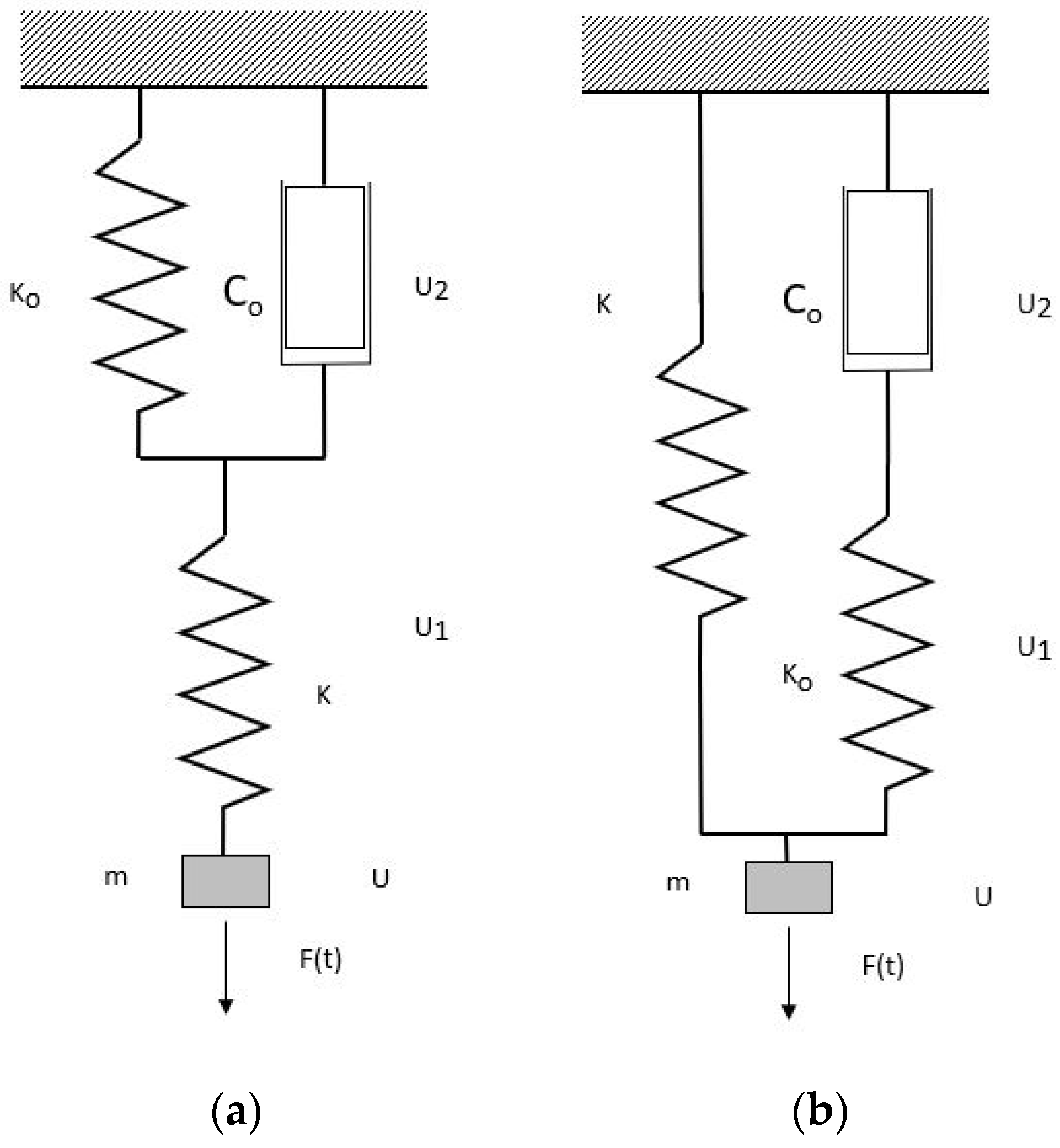
6], we note the relationship between the polished rod force and the displacement resembles that of a typical viscoelastic material, in which a local force can be proportional to the velocity and the displacement as well as their respective combinations. We introduce first the Kelvin-based viscoelastic model in a dynamic case as shown in
Figure 4, essentially a typical Kelvin viscoelastic setup for creep test combined in series with a spring with a stiffness k and a mass m. The displacement of the parallel section of the stiffness k
o and the dashpot c
o shares the same displacement u
2(t), whereas the displacement of the stiffness k is denoted as u
1(t). Since the mass m is connected with the stiffness k in series, the total displacement of the mass u(t), is a combination of the two displacements u
1(t) and u
2(t). In general, the external load F(t) is directly applied to the mass point which has a finite mass m. Notice here this external load will be replaced with the polished rod force as measured by the Echometer dynamometer in our attempt to replace the entire downhole sucker rod pump system with such a Kelvin viscoelastic model. We can imagine that in a creep test we can simply add a dead weight W
o in addition to the weight mg of the mass m.
Using the procedure to identify dynamic and kinematic governing equations, consider for each section in series that we have consequent continuity of axial forces and combination of displacements and for each section in parallel we have consequent continuity of displacements and combination of forces; therefore, we have:
Using the kinematic relationship
, we obtain the following third-order governing equation for u
2(t),
Let us look at two special cases. First of all, with no dashpot, namely, c
o = 0. In this case, we have:
hence,
Finally, the governing dynamic equation yields the familiar spring-mass vibration system for this setup with two stiffness or springs connected in series:
with the familiar effective stiffness of two springs in series.
The second special case corresponds to the infinite stiffness k, namely, k
, consequently, we have
and
. Finally, we recover the familiar spring-mass-dashpot vibration system
To facilitate the solution, we can rewrite the third-order viscoelastic vibration system with a standard dynamic system format,
with the state variable
, and,
Let us consider the Maxwell-based comparable viscoelastic model in a dynamic case as shown in
Figure 4, essentially a typical Maxwell viscoelastic setup for a relaxation test combining a mass m in series connecting with two parallel branches, one with a stiffness k and another one with a stiffness k
o, and a dashpot c
o in series. The displacement of the parallel section shares the same value u(t), whereas the displacement of the stiffness is denoted as u(t) and the dashpot c
o with the displacement u
2(t) connected in series with the stiffness k
o with the displacement u
1(t). Since the displacement of the stiffness k is u(t), naturally, the total displacement of the mass u(t) is a combination of the two displacements u
1(t) and u
2(t) within one of the parallel branches. In general, the external load F(t) is applied to the mass point with a mass m. Likewise, this external load will be replaced with the polished rod force measured by the Echometer dynamometer when we replace the entire downhole sucker rod pump system with the Maxwell viscoelastic model. Again, we can imagine that in a relaxation test, we can simply add a dead weight W
o in addition to the weight of the mass m. Using the same kinematic and dynamic procedures, assuming the force in the dashpot and stiffness series as F
o, we consider each section in series and the consequent continuity of axial forces, and we have:
Using the kinematic relationship
, hence
, we obtain the following third-order governing equation for
,
Let us look at two special cases. First of all, with no dashpot, namely, c
o = 0. In this case, we have F
o = 0, hence the governing dynamic equation yields the familiar spring-mass vibration system:
The second special case corresponds to the infinitely stiff spring k
o, namely,
, consequently,
and u(t)
= . Finally, we recover the familiar spring-mass-dashpot vibration system:
Again, to facilitate the solution, we can rewrite the third-order viscoelastic vibration system as Equation (17), with the state variable
, and,
4. Results
In the following two examples, we employ k = 4 lbf/ft, m = 1 slug, c
o = 0.2 lbf s/ft, k
o = 4 lbf/ft, and W
o = 10 lbf. Both viscoelastic vibration models will start from the zero position with zero velocity and zero acceleration. In our initial numerical tests, the external force F(t) is a dead weight W
o. Based on the numerical integration with central differencing schemes similar to references [
15,
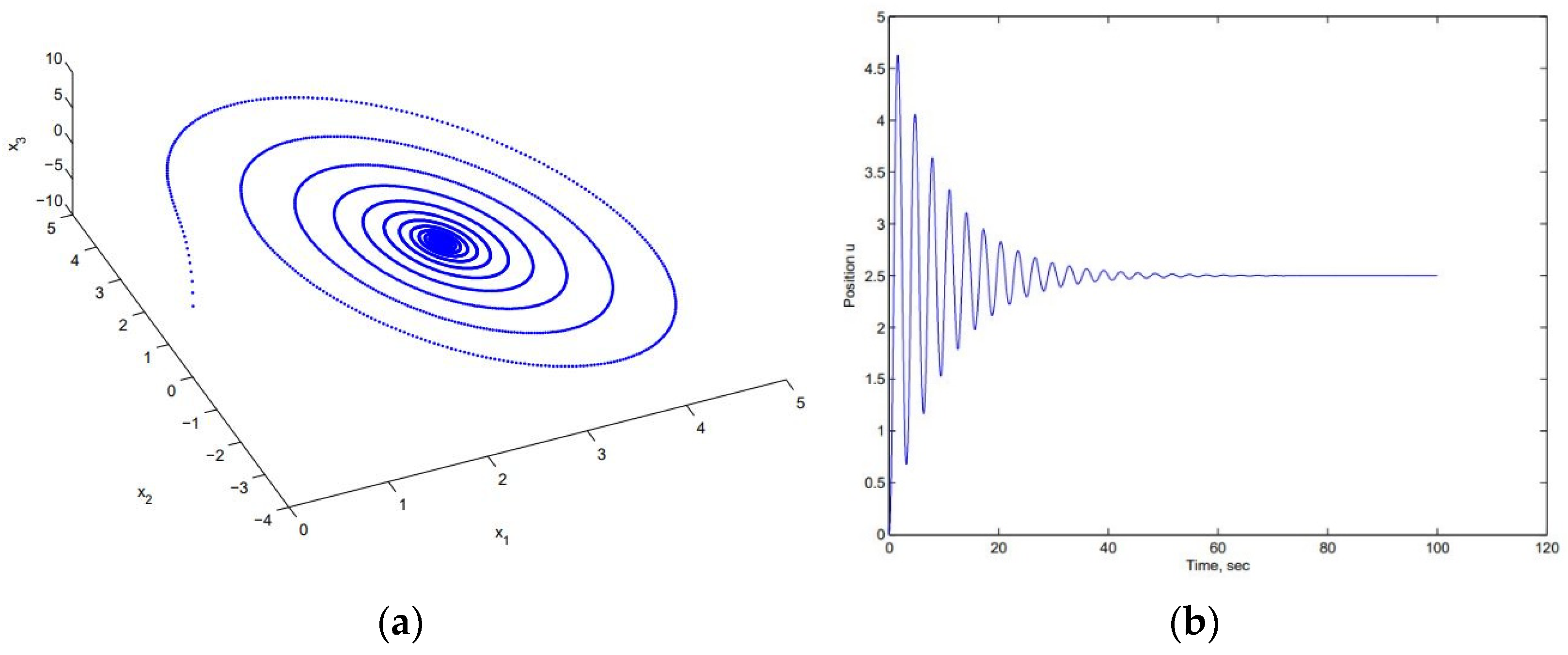
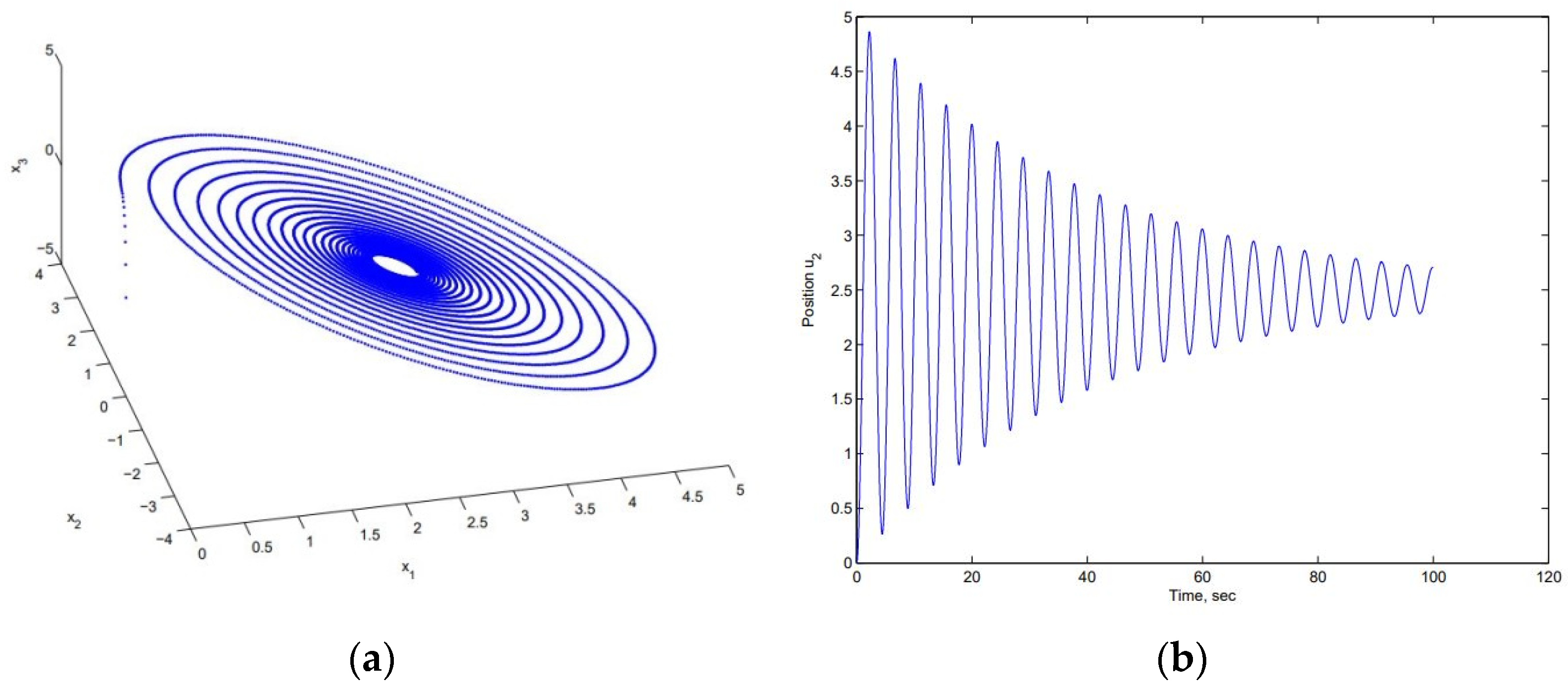
16], we have obtained the dynamic responses of these two third-order differential equations with Maxwell and Kelvin viscoelastic models. As depicted in
Figure 5 and
Figure 6, it is clear that the vibration eventually settles down to an equilibrium position due to the dashpot damping. Of course, in this paper, we will replace the deadweight with the actual polished rod force measured with the dynamometer and use the same numerical scheme to obtain the displacement of the viscoelastic material model representing the actual downhole sucker rod pump systems.
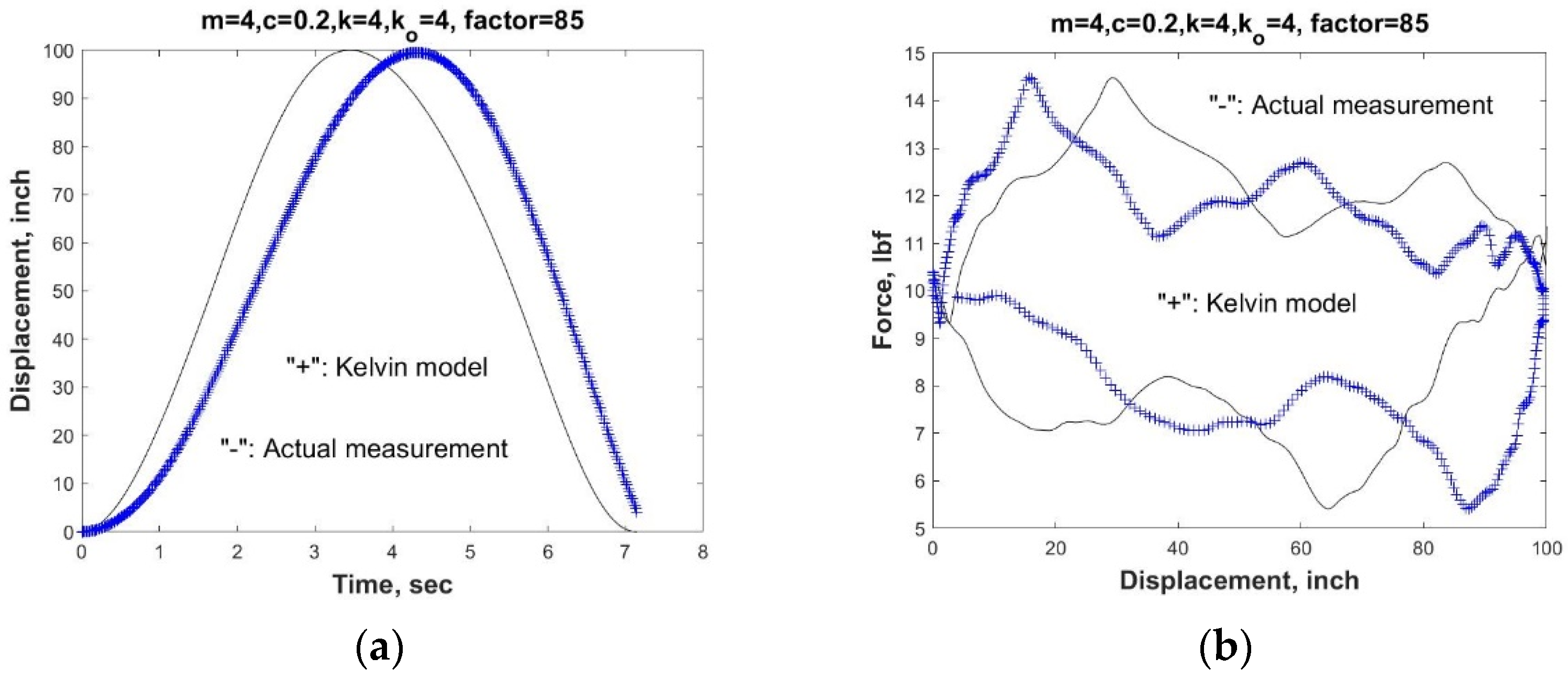
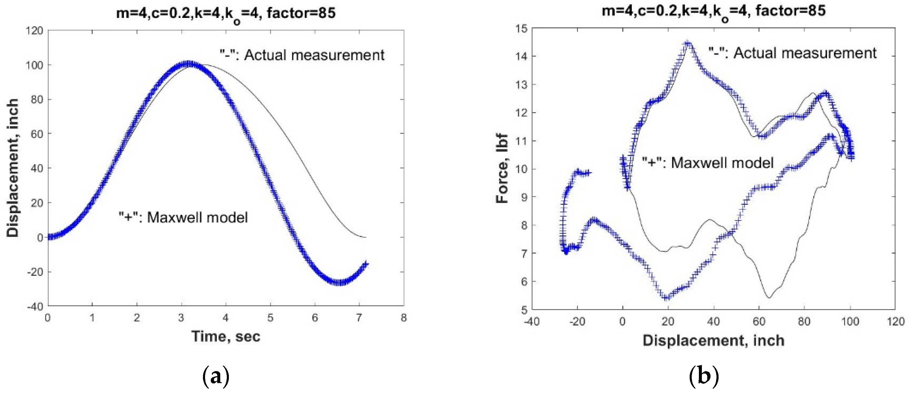
As shown in
Figure 7 and
Figure 8, even with very preliminary Kelvin and Maxwell models, we can still recreate the relationship of the polished rod load and displacement, namely, the pump dynamometer card for the sucker rod pump system. In the simulation, the magnification factor is 85 for both Maxwell and Kelvin models to match the actual large motion of the sucker rod with the viscoelastic model in the simulation. Note again that the load F(t) used in the viscoelastic model is the exact load measurement recorded in one of the Echometer Total Asset Monitor (TAM) software examples.
It is clear that both models work equivalently well, although for quasi-static problems, the Kelvin model is more suitable for creep problems and the Maxwell model is more suitable for relaxation problems. An improved Kelvin viscoelastic vibration system with adjusted parameters m, c
o, and k
o demonstrates a much closer displacement response with the measured polished rod force F(t) as shown in
Figure 9. In fact, the resemblance between the simulated pump card with that of the actual measurement is comparable with recent full-fledged simulation of downhole sucker rod pumps [
17]. The successive cycles will be a repetition of the same force and displacement cycle as depicted in
Figure 9, which is further evidence that this sucker rod pump system functions as a viscoelastic material, not a viscoplastic material in which a permanent deformation will persist. In general, by reducing the parameter m, the peak of the displacement will shift to the left, which corresponds to the increase of the natural frequency and by increasing the parameter c
o, the viscous damping is increased and the starting and the ending points will be closed. Finally, by increasing the stiffness parameter k
o, the end displacement tends to increase.


 ,
, 