Abstract
Bragg scattering of surface gravity waves by an array of submerged bottom-standing non-smooth breakwaters is studied under the assumption of linearized long wave theory. The closed-form long-wave analytical solutions are derived and validated by comparing them with the results available in the literature. The role of various physical parameters such as breakwaters friction coefficient, depth, width and gap between the adjacent breakwaters are investigated by analyzing the reflection and transmission coefficients. Further, the time-domain simulation for the scattering of long gravity waves over multiple breakwaters is analysed for different values of parameters of breakwaters. The results reveal that the rough surface of the breakwater plays a vital role in reducing wave reflection and transmission. Moreover, it is observed that the transmitted wave dissipates completely for larger values of friction parameters. For certain critical angles, change in wave dissipation becomes maximum due to the variation of phase of the incident wave. Various findings can be considered as benchmark results for the design of the non-smooth structures to attenuate the waves based on the Bragg reflection.
1. Introduction
Shoaling, refraction, diffraction, and reflection have an impact on the wave patterns that are created on the water’s surface, causing them to undergo numerous changes. Bragg resonance is one such mechanism that is essential for spotting natural occurrences like earthquakes or free surface oscillations. This phenomenon occurs as a rise and fall of the water surface and often leads to an increase in wave amplitude over time. The mechanism of Bragg resonance was originally investigated by Bragg and Bragg [1] in crystallography. A few decades later, multiple groundbreaking research experimentally, theoretically, and computationally validated the Bragg resonance between surface water waves and undulating bottom topography (e.g., Heathershaw [2], Mei et al. [3], Cho et al. [4]). Bragg resonance could cause destruction when its period matches with the period of another external source, such as the wind, an earthquake, or rapid changes in air pressure. By adding friction to the top surface of the breakwater, one might lessen the resonance amplitude during Bragg resonance. Thus, there is a need to examine the effects of surface friction of a series of breakwaters on Bragg reflection.
There has been significant advancement in the understanding of Bragg scattering of long waves over submerged structures by a number of studies. Additionally, several analytical solutions have been developed based on linear long-wave equation (LWE) or modified mild-slope equation (MMSE). Liu et al. [5] analysed the reflection of waves by four different kinds of Bragg breakwaters such as triangular, rectified sinusoidal, trapezoidal, and parabolic and produced the associated optimal collocation curves for maximum wave reflection. Liu et al. [6] obtained the analytical MMSE solutions for Bragg reflection by a series of sinusoidal ripples and trapezoidal bars. Kar et al. [7] studied the Bragg scattering of long waves by a series of trenches using the solutions of Bessel equations and the findings were corroborated using numerical data produced based on the boundary element approach (BEM). Kar et al. [8] examined the Bragg scattering of long waves by an array of flexible floating plates in the presence of several submerged trenches. Gao et al. [9] analysed the Bragg resonance produced by deploying a sequence of sinusoidal bars with varying amplitudes and numbers outside a harbour. The interplay of waves, currents, and surges in a region of the shallow continental shelf was explored by Sahoo et al. [10]. Barman et al. [11] investigated the Bragg scattering of long flexural gravity waves by an array of submerged trenches in the perspective of blocking dynamics. Kar et al. [12] discovered the Bragg scattering of surface gravity waves due to surface wave interaction with multiple bottom undulations and a semi-infinite floating flexible structure. Boral et al. [13] investigated the role of viscous damping in the flexural gravity wave interaction in shallow water waves. Guo et al. [14] explored the phase downshift or upshift of Bragg resonance for water wave reflection by an array of cycloidal bars or trenches using the mild slope equation approach. Liu et al. [15] developed MMSE-based analytical modelling to study wave reflection by a single cycloidal geo tube or trench. Xie et al. [16] studied the long wave reflection by an array of submerged trapezoidal breakwaters on a sloping seabed.
The Bragg resonant reflections over several arrays of smooth, impermeable breakwaters were studied by a number of researchers (see Kar et al. [17] and Vijay et al. [18]). However, in actual use, breakwaters are often porous and not smooth. These structures withstand wave resonance and absorb and dissipate wave energy due to its non-smooth/friction nature. Losada et al. [19] explored monochromatic oblique wave propagation across and through porous beds or on a submerged rectangular structure. Few researchers have investigated water flows and resonant waves across the basin that entail the presence of wind and friction (see Visser et al. [20]). Additionally, Mullarney et al. [21] employed analytical technique to analyze wave propagation in a basin in the presence of bottom friction, while Reef et al. [22] investigated using numerical methodology. Ni et al. [23,24] examined the Bragg resonant reflection of water waves by Bragg breakwaters of two forms of porous bars, namely rectangular and trapezoidal, on a sloping permeable seabed. Magdalena et al. [25] analysed the attenuation of waves by mangroves which are modelled as porous structures. Magdalena et al. [26] performed both analytical and numerical studies for seiches in a closed basin with bottom friction. Magdalena et al. [27] investigated the resonance phenomena in lakes using a mathematical model. Subsequently, Magdalena et al. [28] examined the resonant periods of earthquakes in semi-closed basins with complicated bottom topography.
Furthermore, the effect of the rough surface of a rectangular submerged breakwater on resonance phenomena was studied by Magdalena et al. [29] using staggered finite volume method. They determined the optimal friction coefficient and shows that friction can prevent the resonance, even reduce the wave amplitude. Using a mathematical model based on the shallow water equations model, Magdalena et al. [30] simulated the resonance phenomena in basins of various shapes. They demonstrated that if either one of the mode parameters of rectangular basin is zero, a lower value of friction will be needed to prevent the wave resonance otherwise the value of the rougher bottom must be increased to prevent the incoming wave from resonating. Magdalena et al. [31] reported the effect of bottom friction on harbour oscillation for the three different harbour geometry (rectangular, triangular, and semi-parabolic). The results show that a relatively small value of friction is sufficient to prevent resonance in rectangular harbours whereas for the triangular harbour, a larger value of friction requires to prevent resonance. As rough surface plays a vital role on reduction of incidence wave energy, Bragg resonance occurring due to the multiple structures can be reduced by considering rough surface of the breakwaters. This has motivated the authors to study the role of rough surface of multiple bottom-standing structures on Bragg scattering using transform matrix method (TMM).
The rest of the paper is organised as follows: The detailed formulation of the physical model is given in Section 2. The details of the used Transfer Matrix Method and solution of the mathematical model are described in Section 3. The impact of roughness of the breakwaters on Bragg resonance and the role of various physical parameters such as breakwater width and depth, and the gap between the adjacent sides of breakwaters on Bragg scattering are analysed in Section 4. The shape of wave packets in time-domain interacting with rectangular smooth/non-smooth breakwaters is demonstrated in Section 4.1 for various values of the breakwater width, depth, breakwater friction, and initial width of the wave packet. Finally, the important observations are highlighted in Section 5.
2. Mathematical Formulation
The scattering of surface gravity waves by an array of non-smooth breakwaters is investigated analytically using the technique of Transfer Matrix Method (TMM) under the assumption of long wave theory. The problem is studied in the two-dimensional Cartesian coordinate system with plane being assumed as the horizontal plane and z-axis being directed vertically upward. The position of the series of breakwaters associated with water depths is shown in Figure 1. It is assumed that the motion is simple-harmonic in time with angular frequency (see Dingemans [32], Behera and Sahoo [33]). Thus, the free surface elevation is assumed to be of the form Re where, , is the spatial component of the free surface elevation with being the incident wave number. Under the assumption that u, and v are the velocity component of the fluid in two dimensions along x, and directions respectively, the equation of motion can be expressed (see as Sahoo [34] for details) as
with g being the acceleration due to gravity. Moreover, the continuity equation associated with the linearized long wave equation is given by

Figure 1.
Schematic of wave motion over the non-smooth surface of rectangular breakwaters.
Thus, from Equations (1) and (2), the two-dimensional long wave equation over the flat bottom is expressed as
To account for the roughness of the breakwater, the two-dimensional linearized long waves equations are modified by adding friction component and that represents bottom friction where being the friction coefficient. This correction is included into the equation of motion Equation (1). As a result, the enhanced model may be expressed (see [26,29,30]) as
After eliminating from Equations (4)–(6), the two-dimensional long wave equation in terms of can be expressed as
Thus, the two-dimensional long wave equation over the breakwater region can be expressed in terms of as
where k is the solution of the dispersion equation .
3. Closed-Form Analytical Solution
The small amplitude long gravity waves propagating over the series of submerged rectangular breakwaters as shown in Figure 1 are studied analytically using the technique of matrix multiplication. The form of solutions of Equations (3) and (8) in smooth and non-smooth regions having constant depths and respectively are expressed as
where with , and and the unknown complex amplitudes of the reflected and the transmitted waves respectively. The unknowns constants , and , which are related to the amplitudes of the waves propagating along rough and smooth sea bed region respectively. Moreover, the reflection and transmission coefficients are defined as
Transfer Matrix Method (TMM)
Various unknown constants in Equation (9) are obtained using the boundary conditions on the breakwater boundaries along with the interface boundaries following the transfer matrix method (see Zeng et al. [35]) which is briefly discussed in the subsequent discussion.
Assuming as an interface boundary, continuity of pressure and flow fluxes across the interface boundaries of the breakwater and open water regions yield
Using the matching conditions at as in Equations (9) and (11) yields
where , . Using the matching conditions at for , Equation (9) yields
Similarly, using the matching conditions at for , Equation (9) yields
where , .
4. Results and Discussions
To analyze the effects of different waves and structural parameters on wave scattering over a non-smooth array of breakwaters for numerical computation, numerical codes are written using MATLAB software. It is pertinent to mention that certain physically realistic values of the wave and structural parameters, which are listed in Table 1, are used in the computation for an efficient breakwater system. Furthermore, in the subsequent numerical results and discussion, the legend and caption of the figures highlights the values of different physical parameters which are different from the parametric values mentioned in Table 1.

Table 1.
Numerical data employed for computation.
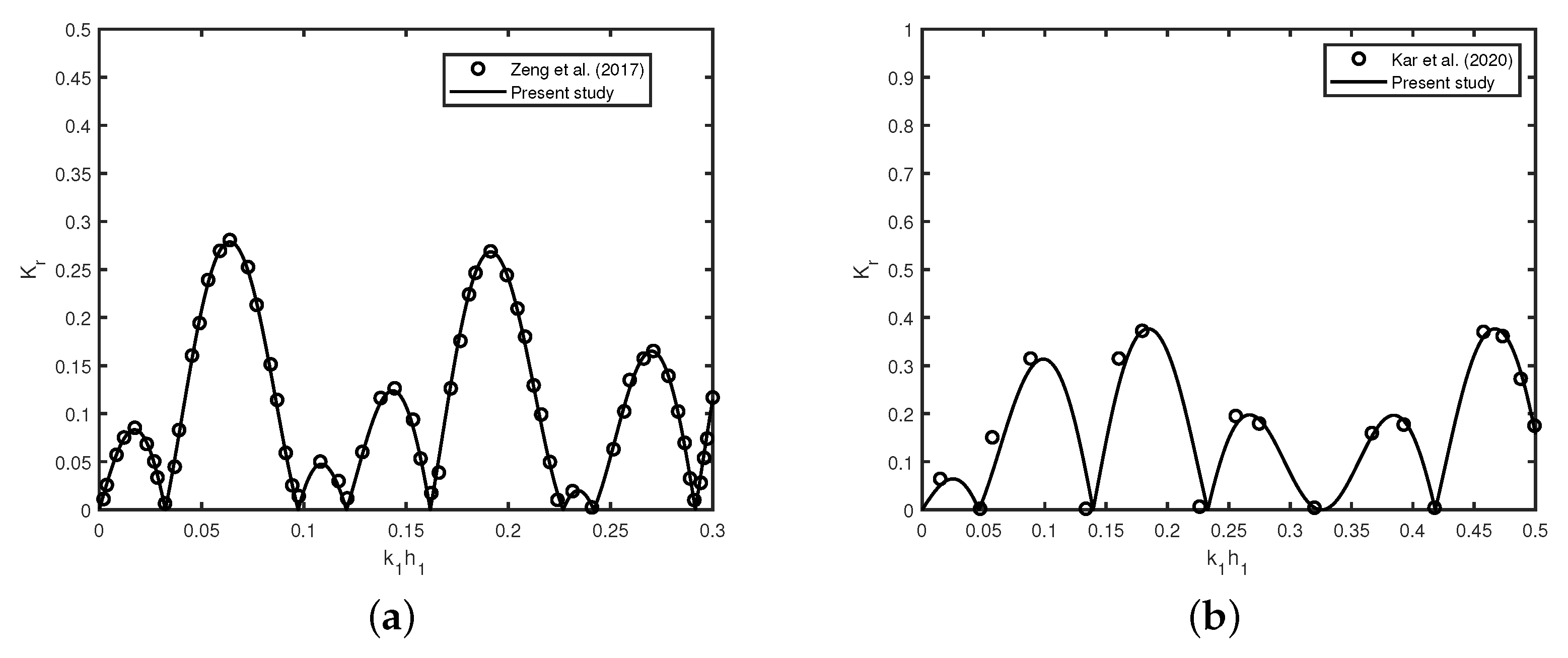
The variation of the reflection coefficient against non-dimensional wave number for double smooth surface bottom-standing rigid breakwaters and trenches is depicted in Figure 2a,b, respectively. The primary objective of these two figures is to validate the present result with published results in two different special cases. Thus, in Figure 2a,b, two different sets of parameters are taken from Zeng et al. [35] and Kar et al. [7], respectively for the purpose of validation. Figure 2a reveals that the results obtained by present theory is well matched with the results of Zeng et al. [35] for long wave scattering by multiple breakwaters with m, m, m, m. In addition, in Figure 2b, the variation of reflection coefficient against wave number is plotted in the case of normal incident waves with double smooth trenches, which agree well with Figure 3a in Kar et al. [7] for m, , , with . In both the figures, Bragg resonance occurs due to the presence of a pair of smooth structures where . In the subsequent figures, the effect of friction parameter on Bragg resonance through the reflection, transmission, and dissipation coefficients is analysed for various wave and structural parameters.
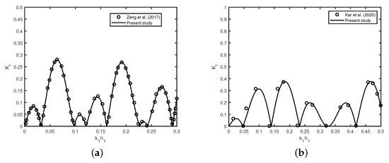
Figure 2.
Variation of reflection coefficient versus wave number for (a) double breakwaters and (b) double trenches in the absence of friction . Here, ∘ indicates Zeng et al. [35] and − specifies Kar et al. [7].
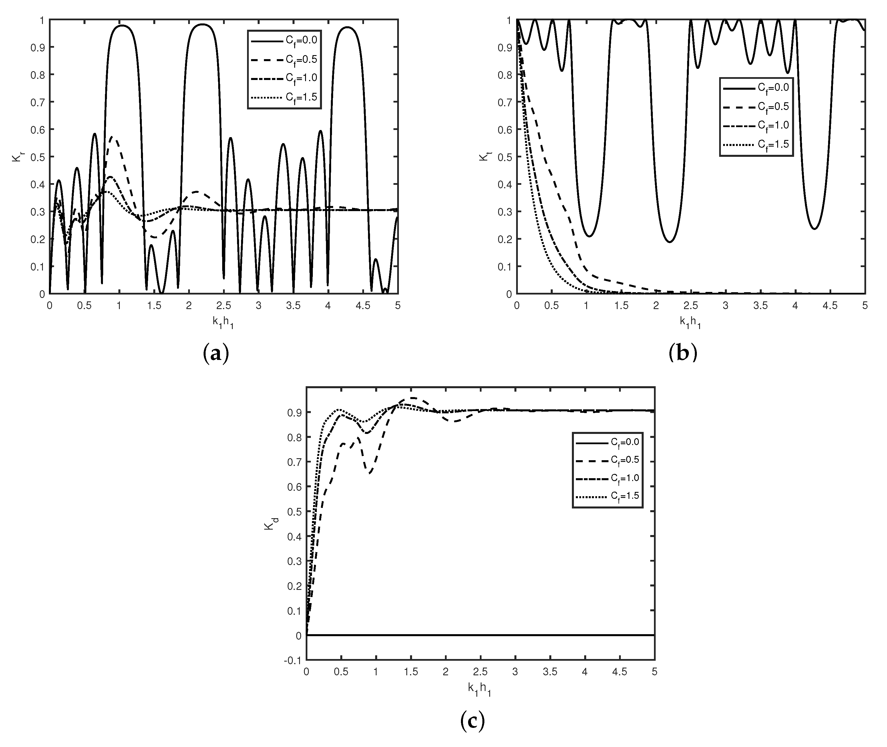
In Figure 3, the variation of (a) reflection coefficient , (b) transmission coefficient , and (c) dissipation coefficient versus wavenumber are plotted for different values of frictional coefficients with , , , , , m. Figure 3a shows that Bragg reflection occurs for wave scattering by an array of multiple smooth breakwaters (), which is similar to that of Kar et al. [7,12]. In Figure 3a,b, the occurrence of zero reflection and full transmission in the absence of friction happens due to constructive and destructive interference of the trapped waves. The peaks in each bandwidth of Bragg reflection coefficient remain periodic with an increase in wave number . In the presence of friction , the periodic pattern in the reflection coefficient is not observed which happens due to the dissipation of the incident wave energy by the non-smooth breakwater. These similar phenomena were observed by Gayathri et al. [36]. Further, it is observed that for certain range of wavenumber i.e., , wave reflection decreases as friction parameter increases. Figure 3b reveals that no wave is transmitted in the presence of friction for . Moreover, for wave number , transmission coefficient decreases as the value of friction parameter increases which is similar as observed in Figure 3a. Figure 3c reveals that for wave number , there is nearly 90% wave energy dissipation happens for irrespective of the value of friction parameter . Figure 3a shows that in the presence of friction, the oscillatory pattern diminishes, which may be due to the dissipation of wave energy. In Figure 3c, variation of energy dissipation in the absence of friction (with ) is zero, which is be due to the distribution of wave energy into the reflected and transmitted waves over the smooth surface of the breakwater.
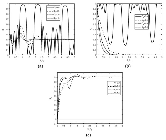
Figure 3.
Variation of (a) reflection coefficient , (b) transmission coefficient , and (c) dissipation coefficient versus wavenumber for different with , , , , , m.
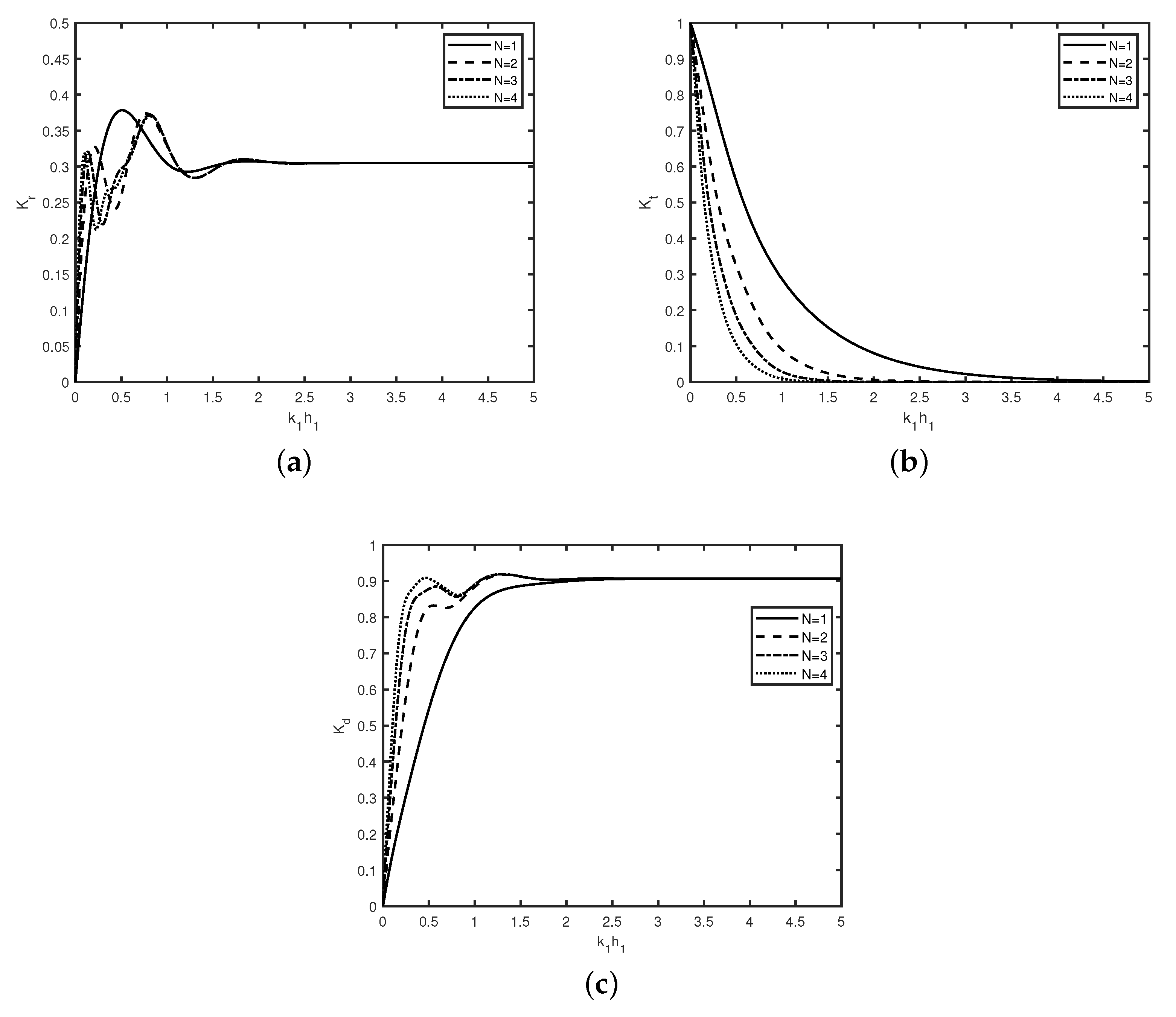
In Figure 4, the variation of (a) reflection coefficient , (b) transmission coefficient , and (c) dissipation coefficient versus wavenumber are plotted for different values of N with , , , , , m. In Figure 4a, the reflection decreases as the number of breakwaters N increases, which is similar as observed in Behera and Sahoo [33]. Furthermore, the reflection coefficient remains constant beyond irrespective of number of breakwaters N which is not the case for smaller wave number. This is due to the fact that the effect of bottom undulation in shallow water region is more as compared to that of the deep water region. Figure 4b depicts that transmission coefficient decays faster as the number of breakwaters N increases. Moreover, in the presence of friction, no Bragg resonance occurs for wave transmission whereas Bragg resonance in wave reflection is observed for wave number . A comparison of Figure 4c with Figure 3c reveals that in both the figures, nearly 90% incident wave energy dissipation occurs for wavenumber irrespective of values of or number of breakwaters N. In Figure 4c, the energy dissipation is due to the increase in the number of non-smooth breakwaters.
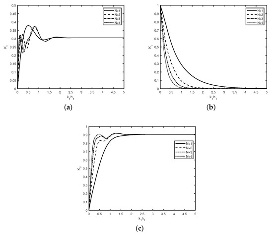
Figure 4.
Variation of (a) reflection coefficient , (b) transmission coefficient , and (c) dissipation coefficient versus wavenumber for different N with , , , , , m.
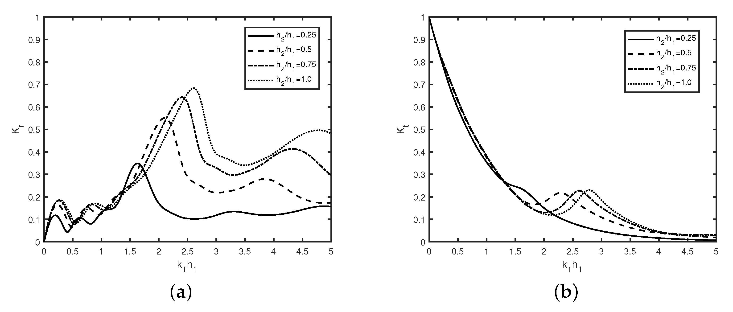
In Figure 5, the variation of (a) reflection coefficient and (b) transmission coefficient versus wavenumber is plotted for different with , , , , , m. Figure 5a depicts that reflection coefficient decreases with an increase in breakwater depth . This is due to the decrease in the height of the non-smooth breakwater which will transmit more wave energy.
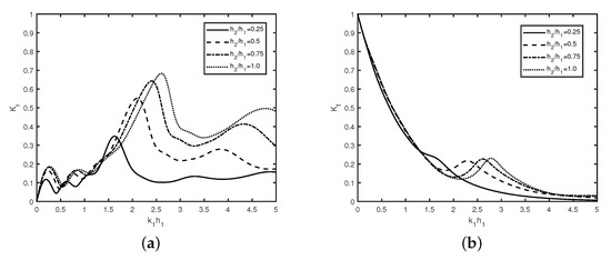
Figure 5.
Variation of (a) reflection coefficient , and (b) transmission coefficient versus wavenumber for different with , , , , , m.
Moreover, in the presence of friction , the reflection coefficient follows an oscillatory pattern with an increase of wave number . The peaks in the wave reflection shift forward with an increase in wavenumber . The shifting of peaks is due to the phase change in the reflected and transmitted waves. In Figure 5a, zero reflection does not occur as the height of breakwaters increases, which is similar to the observation as studied in [33]. Furthermore, it is observed that the number of peaks remains the same irrespective of the values of breakwaters depth. Figure 5b depicts that there is negligible variation of transmission coefficient observe for smaller values of wavenumber i.e., . Moreover, the transmission coefficient increases with an increase in breakwater depth . The zero transmission occurs for higher values of wavenumber . Both figures reveal that breakwater height plays a major role to reflect the wave energy toward the seaside.
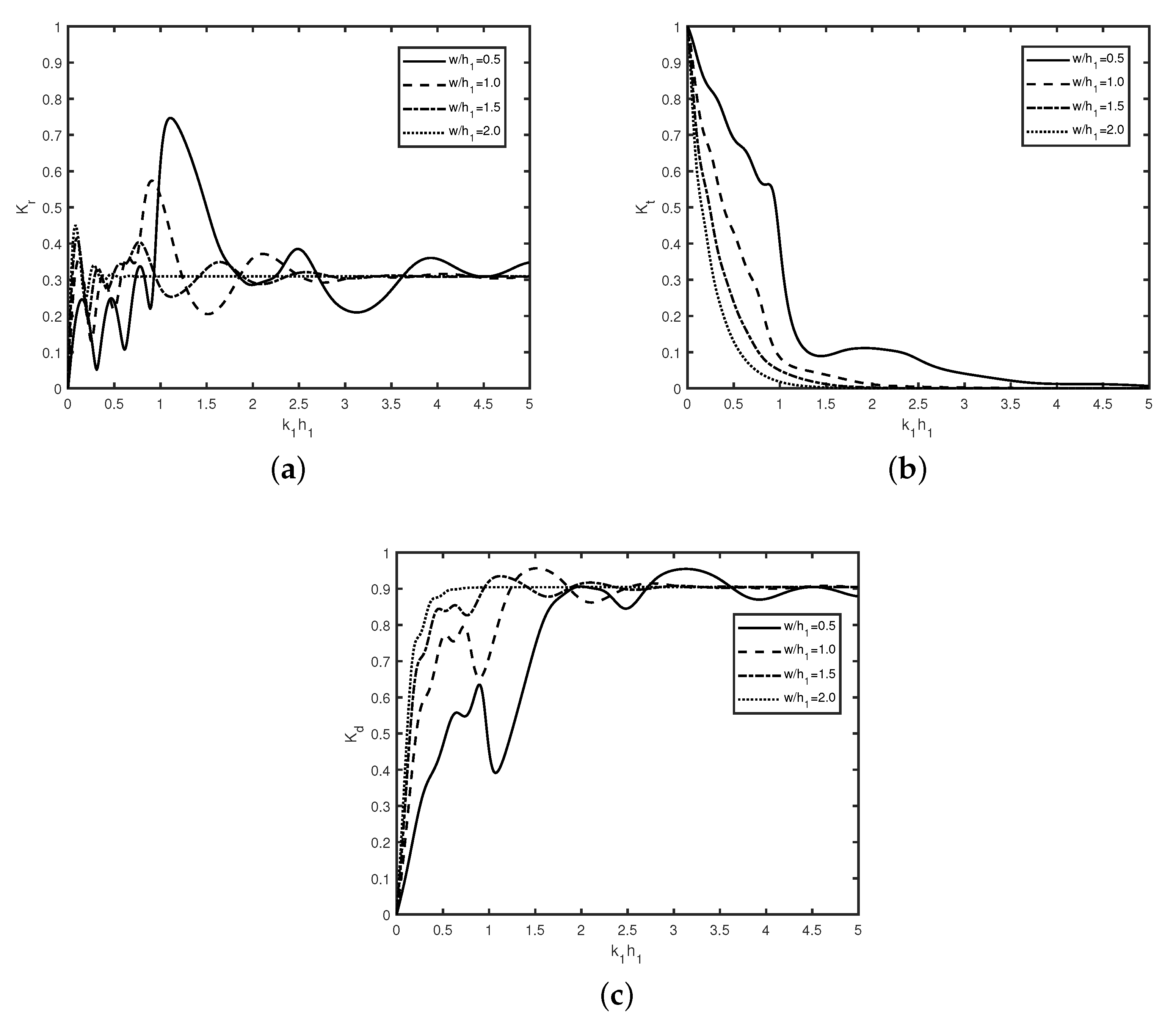
Figure 6 describes the variation of (a) reflection coefficient , (b) transmission coefficient , and (c) dissipation coefficient against wavenumber for different breakwater width with , , , , , . It is found that reflection coefficient follows an oscillatory pattern with an increase in wavenumber . Moreover, the oscillatory pattern of reflection coefficient demises with an increase in width of the breakwater . Further, it is observed that after a certain width, wave reflection remains constant. The number of resonating peaks for smaller breakwater width is more compared to the higher values of breakwater width . Moreover, the oscillatory pattern in wave transmission is not observed. This is due to the dissipation of incident wave energy by the rough surface of the multiple breakwaters. A comparison between the Figure 6a,b reveal that an oscillatory pattern in wave reflection occurs whereas no oscillatory peaks are observed in wave transmission. In general, dissipation of incident wave energy increases with an increase in width of the breakwaters as shown in Figure 6c. Additionally, dissipation coefficient varies significantly for smaller wave numbers with which ensures that the present physical model is more suitable for the long waves as compared to that of short waves. A comparison of Figure 5 and Figure 6 reveals that in the presence of friction , the changes in transmission coefficient are observed more as compared to that of the reflected coefficient .
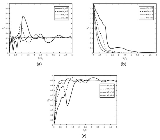
Figure 6.
Variation of (a) reflection coefficient , and (b) transmission coefficient , (c) dissipation coefficient versus wavenumber for different with , , , , , m.
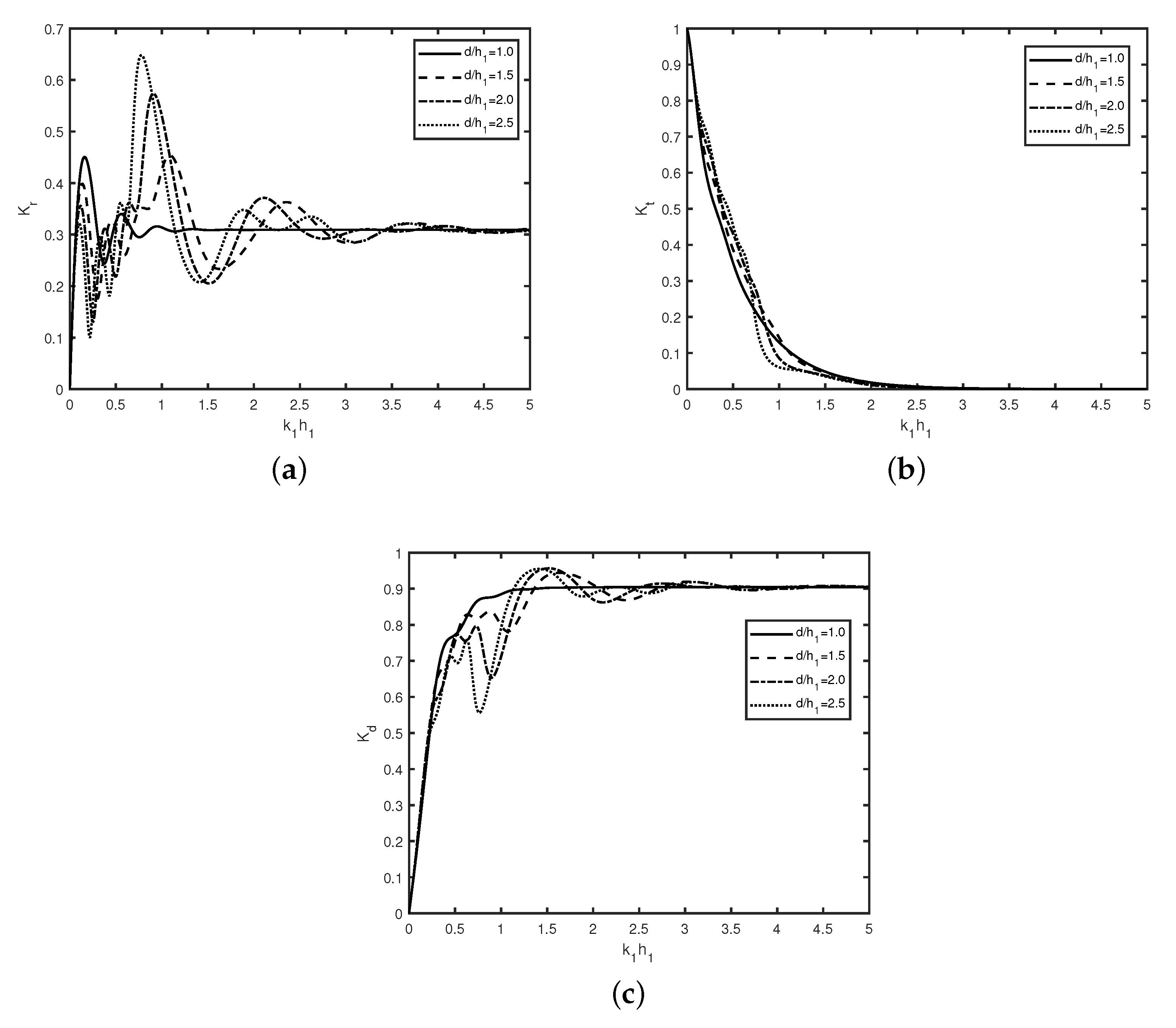
In Figure 7, the variation of (a) reflection coefficient , (b) transmission coefficient , and (c) dissipation coefficient against wavenumber is plotted for different gap between the adjacent breakwaters with , , , , , m.
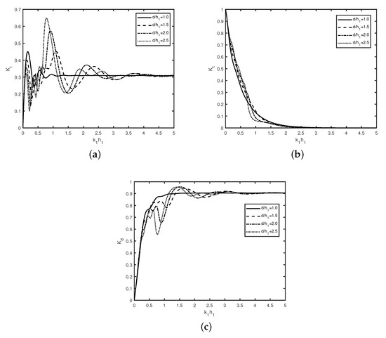
Figure 7.
Variation of (a) reflection coefficient , and (b) transmission coefficient , (c) dissipation coefficient versus wave number for different with , , , , , m.
Figure 7a reveals that the peaks in the reflection coefficient decreases as gap between the adjacent sides of breakwaters increases which is same as observed in Figure 6a. Moreover, the mutual interaction between incident, reflected and transmitted waves decrease for higher gap gap between the structures thus, the oscillation in wave reflection demises as gap increases. Furthermore, due to this reason, the number of resonance peaks in the reflection coefficient decreases as the distance widens. Figure 7b shows the changes in transmission coefficient are very little as the gap between the breakwaters increases. Moreover, a comparison between the Figure 7a,b reveals that oscillatory trend is observed in wave reflection which is not the case with wave transmission. Figure 7c shows that the peaks in the dissipation coefficient decrease as the gap between the adjacent side of breakwaters increases. A comparison of Figure 7c with Figure 4c and Figure 6c and reveals that 90% of the incident wave energy dissipates irrespective of gap between the adjacent breakwaters or number of breakwaters N.
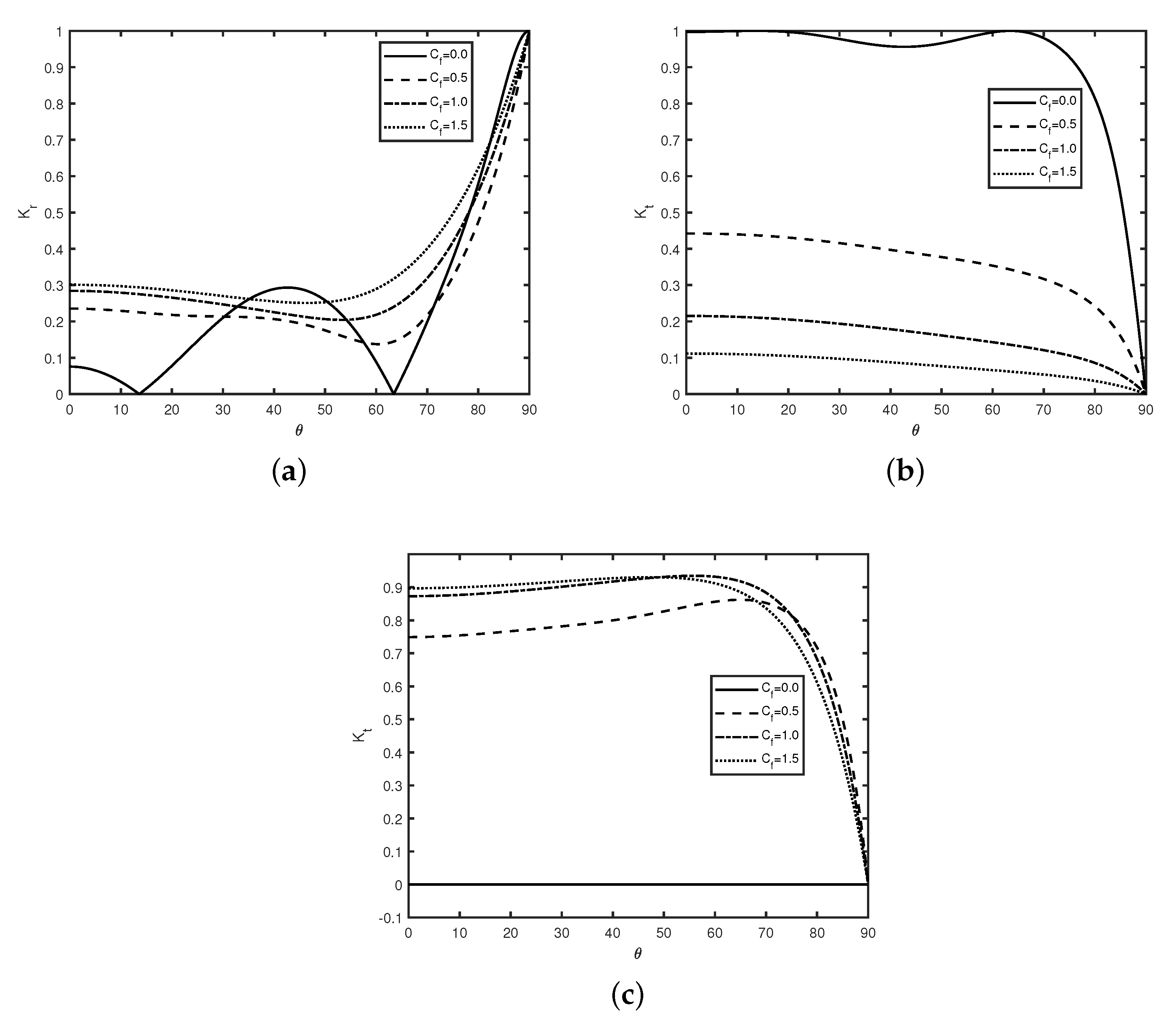
In Figure 8, the variation of (a) reflection coefficient , (b) transmission coefficient , and (c) dissipation coefficient versus angle is plotted for different values of with , width , , and . Figure 8a shows that the reflection coefficient increases rapidly after a certain angle i.e., nearly as the value of the friction parameter increases. Moreover, in the absence of friction (), zero reflection occurs for certain countably many angles which is similar as observed in [33]. The occurrence of zero reflection is due to the destructive interference of reflected and incident waves. However, zero reflection does not happen in the case of breakwaters with rough surfaces () because of the dissipation caused by the structures. Further, a comparison with Figure 4a exhibits that the oscillatory pattern diminishes as the friction coefficient increases. Figure 8b evinces that the transmission coefficient decreases with an increase in angle which is obvious as reflection coefficient increases with an increase in angle . Moreover, in the absence of friction, full transmission occurs for certain values of angle , which is due to the constructive interference of the resonating waves. Figure 8c shows that for higher values of friction parameter , more energy dissipation occurs and in the absence of friction, no dissipation occurs. Therefore friction parameter plays a major role in the dissipation of wave energy.
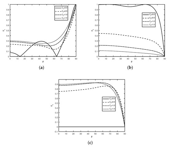
Figure 8.
Variation of (a) reflection coefficient , (b) transmission coefficient , and (c) dissipation coefficient versus angle for different values of with , width , , and .
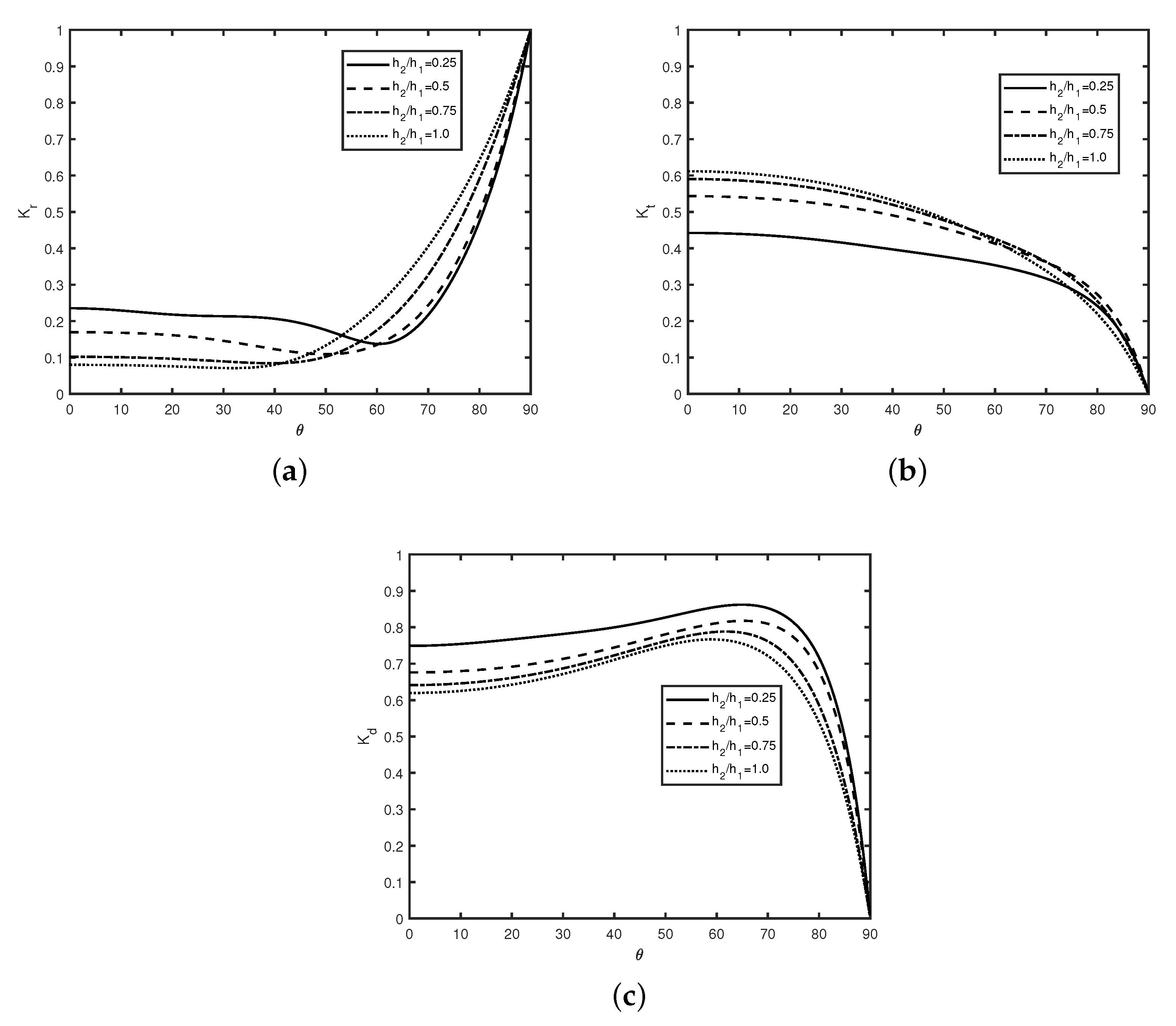
Figure 9 reveals the changes in (a) reflection coefficient , (b) transmission coefficient , and (c) dissipation coefficient versus angle for different values of breakwater depth with breakwater width , , and . Figure 9a shows that reflection coefficient increases with an increase in angle . Moreover, Figure 9a shows that for greater values of a certain angle, the reflection coefficient increases with an increase in breakwater depth whereas for smaller values of a certain angle, reflection follows the reverse pattern. Figure 9b reveals the transmission coefficient decreases with an increases in angle . Moreover, it is observed that transmission coefficient decreases as breakwater depth increases. Figure 9c shows that dissipation coefficient increases as breakwater depth decreases. Further, Figure 9c reveals that in the presence of friction , for a certain angle i.e., nearly at , the maximum wave dissipation occurs.
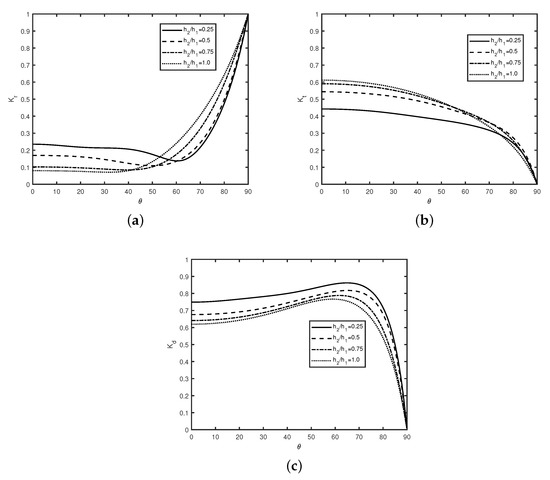
Figure 9.
Variation of (a) reflection coefficient , (b) transmission coefficient , and (c) dissipation coefficient versus angle for different values of with breakwater width , , and .
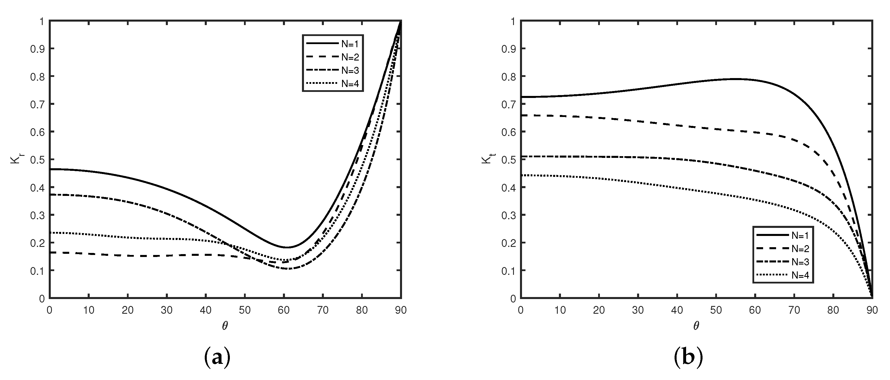
In Figure 10, the variation of (a) reflection coefficient and (b) transmission coefficient versus angle is plotted for different values of N with breakwater width , , ,, and . Figure 10a reveals that the reflection coefficient decreases with an increase in the number of breakwaters N. Moreover, the reflection coefficient increases with an increase in the number of breakwaters N as observed in [26]. Further, it is observed that common minima occur in the case of an even number of breakwaters, whereas common maxima occur in the case of an odd number of breakwaters as the angle of propagation increases. Moreover, the bandwidth of each harmonic peak increases with an increase in the number of breakwaters N. Further, Figure 10b reveals that the position of the band of each cycle remains fixed with an increase of oblique angle irrespective of the number of breakwaters N. Moreover, for a certain angle, , the wave reflection becomes completely zero which may be due to the phase mismatch of the resonating waves.
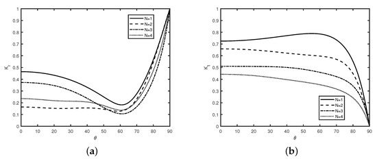
Figure 10.
Variation of (a) reflection coefficient and (b) transmission coefficient versus angle for different values of N with breakwater width , , , , and .
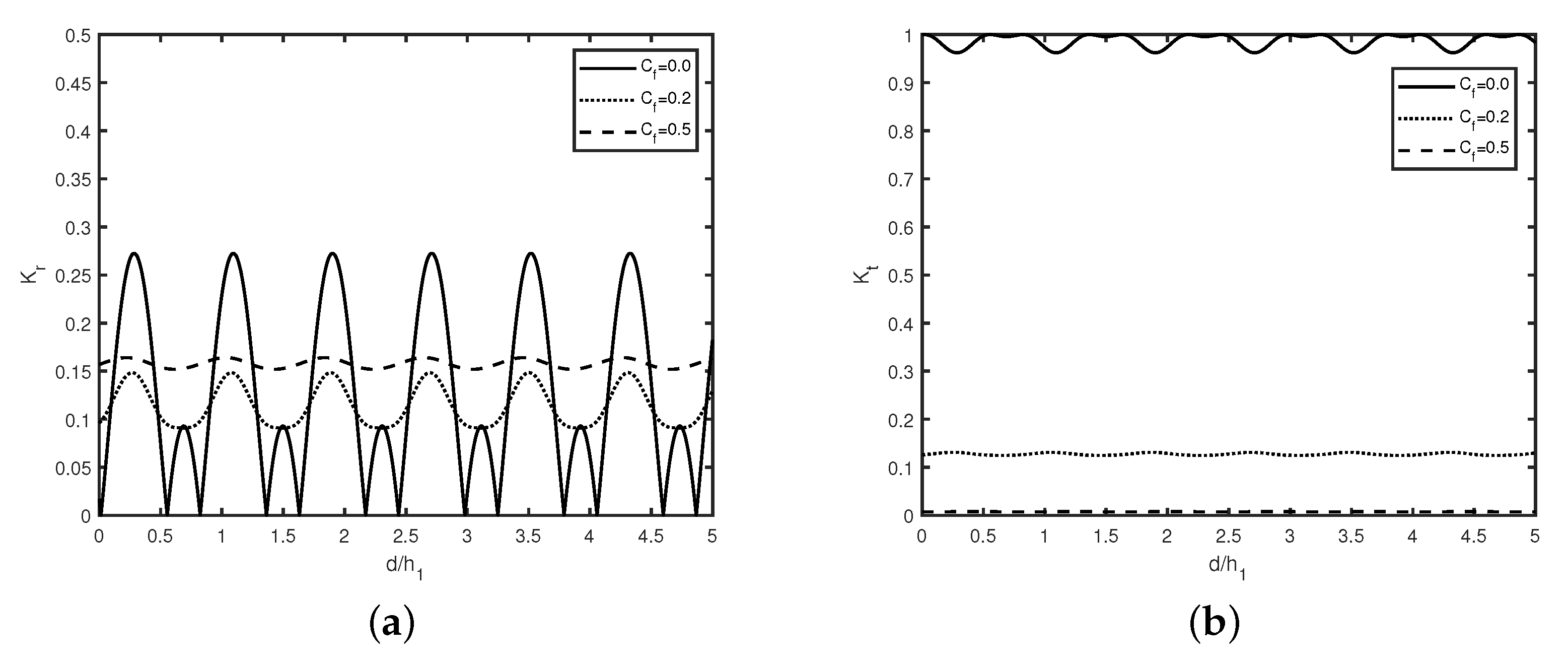
Figure 11 describes the changes of (a) reflection coefficient , and (b) transmission coefficient against gap between the breakwater for different values of with breakwater width , , . Figure 11a reveals that reflection coefficient follows a periodically oscillatory pattern with an increase in the gap between the adjacent breakwaters which is similar as observed in [17]. Further, the amplitude of the peaks in each band decreases with an increase in friction coefficient . Further, the sub-harmonic peaks demise with an increase in friction coefficient . Further, Figure 11b reveals that in the absence of friction, full transmission occurs for finitely many The position of the band of each cycle remains fixed with an increase of oblique angle irrespective of the number of breakwaters N. Moreover, for certain angle , the wave reflection becomes completely zero which may be due to the phase mismatch of the resonating waves. In Figure 11a, wave reflection decreases due to the damping of wave energy.
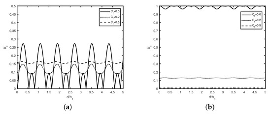
Figure 11.
Variation of (a) reflection coefficient , and (b) transmission coefficient versus gap for different values of with breakwater width , and .
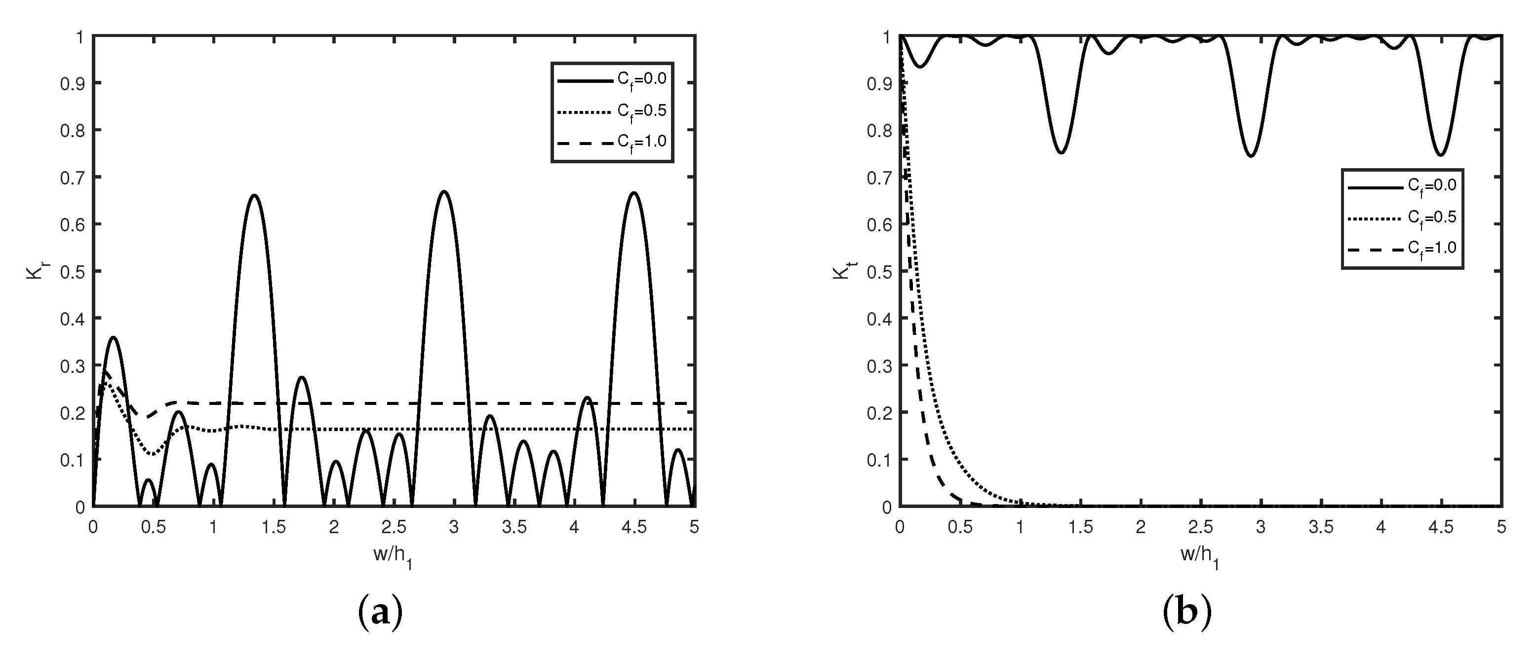
Figure 12 describes the variation of (a) reflection coefficient , and (b) transmission coefficient versus breakwater width for different values of with breakwater width , and . Figure 12a reveals that in the absence of friction, Bragg reflection occurs and follows periodically oscillatory pattern with an increase in breakwater width which is observed in our previous study (see Kar et al. [7,12]). Moreover, the reflection coefficient decreases with an increase in the friction coefficient . Further, the reflection coefficient remains constant after certain values of breakwater width () irrespective of friction coefficient . Further, it is observed that in the absence of breakwater friction, zero reflection occurs for the countably many values of breakwater width . Moreover, the bandwidth of each harmonic peak remains fixed with an increase in the breakwater width . Further, Figure 12b reveals that in the absence of friction, the amplitude of peaks in each band of the cycle remains the same with an increase in width of the breakwater . Moreover, in the absence of friction, the transmission coefficient follows the periodically oscillatory. Further, full transmission occurs for the countably many values of breakwater width . Moreover, in the presence of friction, zero transmission occurs for greater values of certain breakwater width . It is observed that with an increase in breakwater friction , wave transmission coefficient decreases gradually. The periodic pattern in wave transmission vanishes in the presence of friction which is the same as observed in Figure 6b which may be due to phase mismatch of the resonating waves. The results in Figure 12 imply that in the presence of friction, the reduction of wave amplitude happens which may be due to the occurrence of wave energy dissipation.
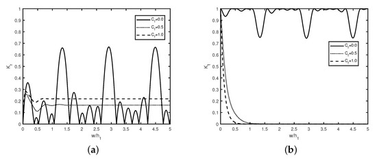
Figure 12.
Variation of (a) reflection coefficient , and (b) transmission coefficient versus breakwater width for different values of with breakwater width , and .
4.1. Time-Dependent Simulations and Numerical Results
The time-dependent results are present for wave packets, which are incident from infinity. The free surface elevation, defined in Section 2 in the time domain, is computed using the formula
with being the Fourier transform of the incident wave pulse. In Equation (18), is the frequency-dependent surface displacement of the open water region. The incident wave pulse is assumed to be a Gaussian wave packet of the form where b is the spreading function and is the central frequency of the incident wave pulse.
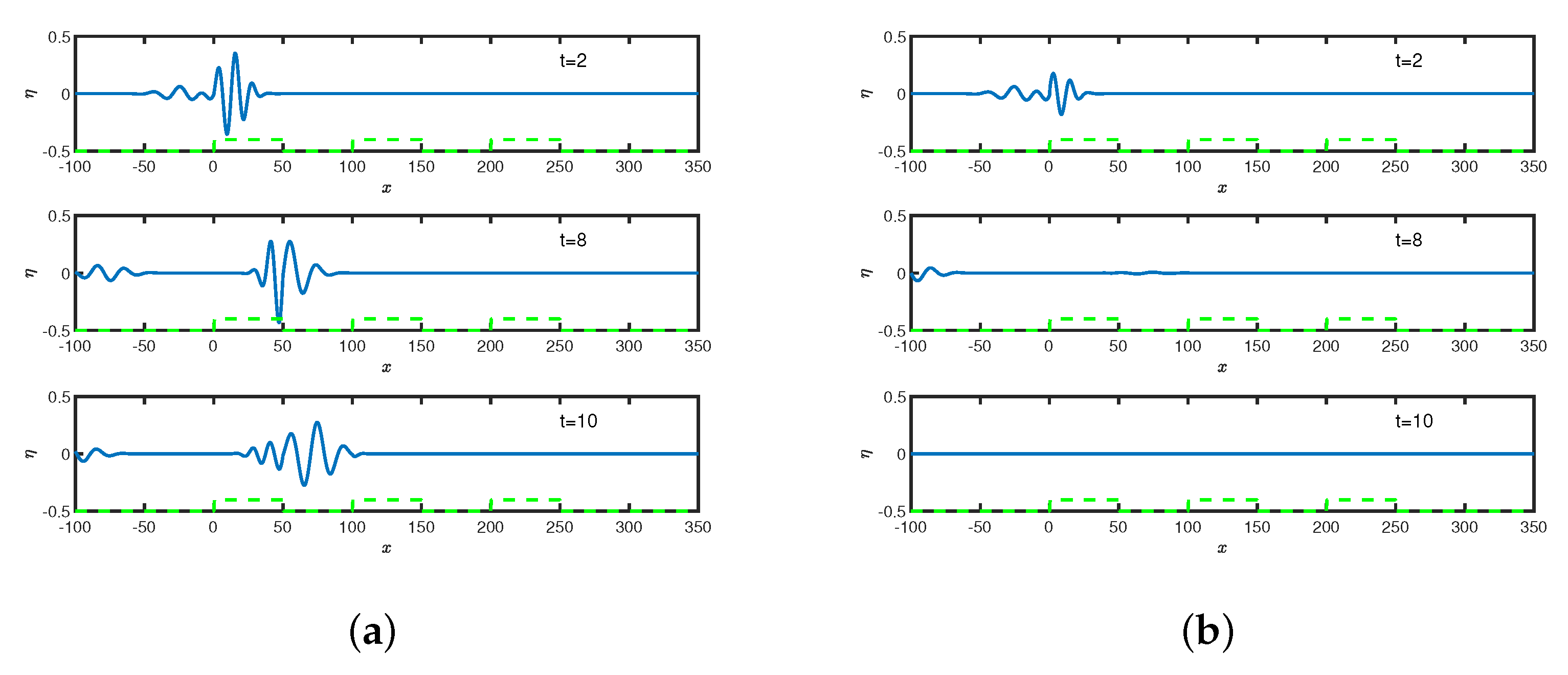
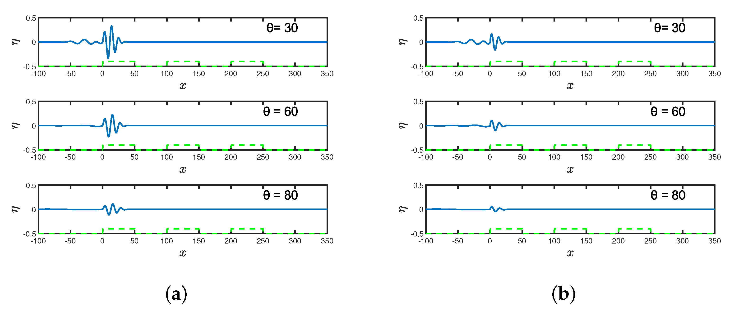
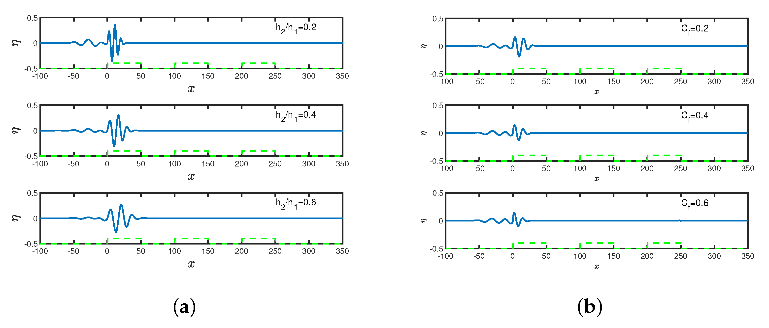
In Figure 13, Figure 14 and Figure 15, the free surface elevation is plotted against spatial variable x for different values of time t, breakwater depth and incident angle in the (a) absence and (b) presence of the breakwater friction with number of breakwaters . Figure 13a, Figure 14a and Figure 15a depict that the amplitudes of wave pulses remain the same along the breakwater as observed in [12], whereas Figure 13b–Figure 15b show that the amplitude of wave pulse reduces in the presence of friction and demises with an increase in time. The amplitude of wave pulse reduces with an increase in time which is due to the dissipation of energy over the rough surface of breakwaters. The occurrence of this phenomena by time domain simulation is well verified with the results observed in Figure 3b. The reduction of the wave pulse happens due to the presence of bottom friction which plays an important role in restricting the unlimited growth of the wave height.
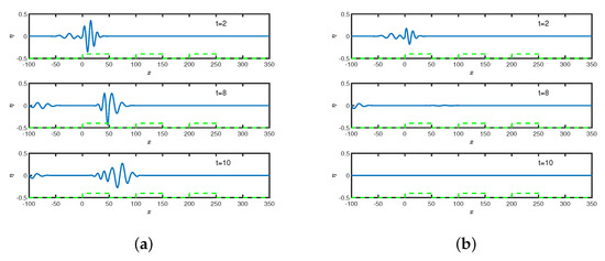
Figure 13.
Free surface elevation versus spatial variable x (a) without friction coefficient and (b) with friction coefficient for with m, , = 0.4.
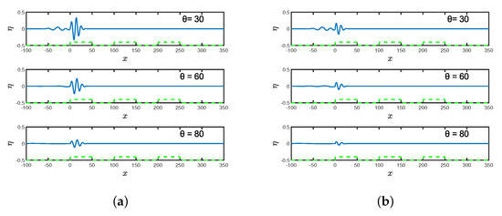
Figure 14.
Free surface elevation versus x for different angle (a) with friction coefficient and (b) with friction coefficient for , s.
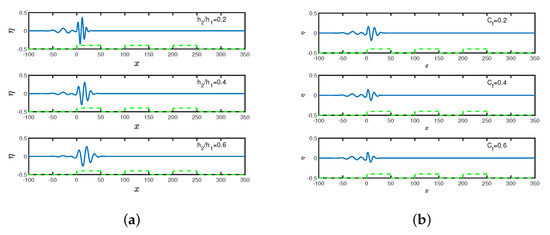
Figure 15.
Free surface elevation versus x for different (a) breakwater depth without friction coefficient and (b) friction coefficient with with m, , s, .
5. Conclusions
Under the assumption of linearized long wave theory, Bragg reflection of surface gravity waves by an array of submerged bottom-standing non-smooth breakwaters is investigated in this study. The linearized shallow water equations are solved analytically using the transfer matrix method to calculate the reflection, transmission and dissipation coefficients. The study reveals that wave transmission decays linearly in the presence of friction, whereas wave reflection follows an oscillating pattern similar to that observed for a pair of breakwaters in the literature as in Magdalena et al. [25]. In the presence of friction, the common minima or maxima of the reflection curve shift upward as the wave number increases. In addition, zero reflection or full transmission does not occur in the presence of friction parameters. Moreover, the transmission coefficient decays linearly in the presence of friction in the case of multiple breakwaters, similar to what has been observed in the literature. In contrast, the amplitude of surface elevation decreases in the presence of friction, which is due to wave dissipation. The present study will provide a helpful basis in the design of an array of submerged breakwaters for coastal protection and can be used as bench mark solution in case of long wave propagation. However, these type of submerged structures would not be very effective in the case of short-period small amplitude waves where wave energy concentration is higher near the free surface than that of long waves as discussed in the present study.
Author Contributions
Conceptualization, T.S.; methodology, H.B. and P.K.; software, P.K. and H.B.; validation, P.K. and H.B.; formal analysis, P.K., H.B. and T.S.; investigation, P.K. and H.B.; resources, T.S.; data curation, P.K. and H.B.; writing—original draft preparation, P.K. and H.B.; writing—review and editing, P.K., H.B. and T.S.; visualization, P.K., H.B. and T.S.; supervision, T.S.; project administration, T.S.; funding acquisition, T.S. All authors have read and agreed to the published version of the manuscript.
Funding
P. Kar acknowledges the support received from Department of Science and Technology, Govt. of India as a research associate at Department of Ocean Engineering and Naval architecture, IIT Kharagpur through award no. DST/CCP/CoE/79/2017(G) when this research work was initiated.
Data Availability Statement
The data that support the findings of this study are available from the corresponding author upon reasonable request.
Conflicts of Interest
The authors declare no conflict of interest.
References
- Bragg, W.H.; Bragg, W.L. The reflection of X-rays by crystals. Proc. R. Soc. Lond. Ser. A Contain. Pap. Math. Phys. Char. 1913, 88, 428–438. [Google Scholar] [CrossRef]
- Heathershaw, A.D. Seabed-wave resonance and sand bar growth. Nature 1982, 296, 343–345. [Google Scholar] [CrossRef]
- Mei, C.C.; Hara, T.; Naciri, M. Note on Bragg scattering of water waves by parallel bars on the seabed. J. Fluid Mech. 1988, 186, 147–162. [Google Scholar] [CrossRef]
- Cho, Y.-S.; Yoon, S.B.; Lee, J.-I.; Yoon, T.-H. A concept of beach protection with submerged breakwaters. J. Coast. Res. 2001, 34, 671–678. [Google Scholar]
- Liu, H.-W.; Luo, H.; Zeng, H.-D. Optimal collocation of three kinds of Bragg breakwaters for Bragg resonant reflection by long waves. J. Waterw. Port Coast. Ocean. Eng. 2015, 14, 04014039. [Google Scholar]
- Liu, H.-W.; Li, X.-F.; Lin, P. Analytical study of Bragg resonance by singly periodic sinusoidal ripples based on the modified mild-slope equation. Coast. Eng. 2019, 150, 121–134. [Google Scholar] [CrossRef]
- Kar, P.; Sahoo, T.; Meylan, M.H. Bragg scattering of long waves by an array of floating flexible plates in the presence of multiple submerged trenches. Phys. Fluids 2020, 32, 096603. [Google Scholar] [CrossRef]
- Kar, P.; Koley, S.; Sahoo, T. Bragg scattering of long waves by an array of trenches. Ocean. Eng. 2020, 198, 107004. [Google Scholar]
- Gao, J.; Ma, X.; Dong, G.; Chen, H.; Liu, Q.; Zang, J. Investigation on the effects of Bragg reflection on harbor oscillations. Coast. Eng. 2021, 170, 103977. [Google Scholar]
- Sahoo, B.; Sahoo, T.; Bhaskaran, P.K. Wave-current-surge interaction in a changing climate over a shallow continental shelf region. Reg. Stud. Mar. Sci. 2021, 46, 101910. [Google Scholar]
- Barman, S.C.; Boral, S.; Sahoo, T.; Meylan, M.H. Bragg scattering of long flexural gravity waves by an array of submerged trenches and the analysis of blocking dynamics. AIP Adv. 2022, 11, 115308. [Google Scholar] [CrossRef]
- Kar, P.; Koley, S.; Sahoo, T. Bragg Scattering of Surface Gravity Waves Due to Multiple Bottom Undulations and a Semi-Infinite Floating Flexible Structure. Water 2021, 13, 2349. [Google Scholar] [CrossRef]
- Boral, S.; Nath, S.; Sahoo, T.; Meylan, M.H. The role of viscoelastic foundation on flexural gravity wave blocking in shallow water. AIP Adv. 2021, 87, 065317. [Google Scholar] [CrossRef]
- Guo, F.-C.; Liu, H.-W.; Pan, J.-J. Phase downshift or upshift of Bragg resonance for water wave reflection by an array of cycloidal bars or trenches. Wave Motion 2021, 106, 102794. [Google Scholar] [CrossRef]
- Liu, H.-W.; Guo, F.-C.; Ni, Y.-L. Analytical Modeling of the Wave Reflection by a Single Cycloidal Geotube or Trench Based on the Modified Mild-Slope Equation. J. Eng. Mech. 2022, 148, 04021152. [Google Scholar]
- Xie, J.-J. Long wave reflection by an array of submerged trapezoidal breakwaters on a sloping seabed. Ocean Eng. 2022, 252, 111138. [Google Scholar] [CrossRef]
- Kar, P.; Koley, S.; Sahoo, T. Scattering of surface gravity waves over a pair of trenches. Appl. Math. Model. 2018, 296, 303–320. [Google Scholar] [CrossRef]
- Vijay, K.G.; Venkateswarlu, V.; Sahoo, T. Bragg scattering of surface gravity waves by an array of submerged breakwaters and a floating dock. Wave Motion 2021, 106, 102807. [Google Scholar] [CrossRef]
- Losada, I.J.; Silva, R.; Losada, M.A. 3-D non-breaking regular wave interaction with submerged breakwaters. Coast. Eng. 1996, 28, 229–248. [Google Scholar] [CrossRef]
- Visser, P.J. Wave basin experiments on bottom friction due to current and waves. Coast. Eng. 1986, 20, 807–821. [Google Scholar] [CrossRef]
- Mullarney, J.C.; Hay, A.E.; Bowen, A.J. Resonant modulation of the flow in a tidal channel. J. Geophys. Res. Ocean. 2008, 113, C10. [Google Scholar] [CrossRef]
- Reef, K.R.G.; Roos, P.C.; Schuttelaars, H.M.; Hulscher, S.J.M.H. Influence of Back-Barrier Basin Geometry on Multiple Tidal Inlet Systems: The Roles of Resonance and Bottom Friction. J. Geophys. Res. Earth Surf. 2020, 125, e2019JF005261. [Google Scholar]
- Ni, Y.-l.; Teng, B. Bragg resonant reflection of water waves by a Bragg breakwater with porous trapezoidal bars on a sloping permeable seabed. Appl. Ocean. Res. 2021, 114, 102770. [Google Scholar] [CrossRef]
- Ni, Y.-L.; Teng, B. Bragg resonant reflection of water waves by a Bragg breakwater with porous rectangular bars on a sloping permeable seabed. Ocean. Eng. 2021, 235, 109333. [Google Scholar] [CrossRef]
- Magdalena, I.; Karima, N.; Rif’atin, H.Q. 1D-2D Numerical Model for Wave Attenuation by Mangroves as a Porous Structure. Computation 2021, 9, 66. [Google Scholar] [CrossRef]
- Magdalena, I.; Rif’atin, H.Q.; Matin, A.M.A. Analytical and numerical studies for Seiches in a closed basin with bottom friction. Theor. Appl. Mech. Lett. 2020, 10, 429–437. [Google Scholar] [CrossRef]
- Magdalena, I.; Karima, N.; Rif’atin, H.Q. A Mathematical Model for Investigating The Resonance Phenomenon in Lakes. Wave Motion 2021, 102669. [Google Scholar]
- Magdalena, I.; Karima, N.; Rif’atin, H.Q. Resonant Periods of Seiches in Semi-Closed Basins with Complex Bottom Topography. Fluids 2021, 6, 181. [Google Scholar] [CrossRef]
- Magdalena, I.; Jonathan, G. Water waves resonance and its interaction with submerged breakwater. Results Eng. 2022, 13, 100343. [Google Scholar]
- Magdalena, I.; Gunawan, D.R.; Matin, A.M.A. The effect of bottom friction in 2D non-homogeneous wave resonance phenomena. Results Eng. 2022, 15, 100464. [Google Scholar] [CrossRef]
- Magdalena, I.; Rif’atin, H.Q.; Aulia, M.; Alvedian, M. Harbour Oscillation with Bottom Friction. Eng. Lett. 2022, 30, 477–483. [Google Scholar]
- Dingemans, M.W. Water wave propagation over uneven bottoms, Part-I—Linear wave propagation. In Advanced Series on Ocean Engineering; World Scientific: Singapore, 1997; Volume 13. [Google Scholar]
- Behera, H.; Sahoo, T. Gravity wave interaction with porous structures in two-layer fluid. J. Eng. Math. 2014, 87, 73–97. [Google Scholar] [CrossRef]
- Sahoo, T. Mathematical techniques for wave interaction with flexible structures. In Coastal Engineering; CRC Press: Boca Raton, FL, USA, 2012. [Google Scholar]
- Zeng, H.; Qin, B.; Zhang, J. Optimal collocation of Bragg breakwaters with rectangular bars on sloping seabed for Bragg resonant reflection by long waves. Ocean. Eng. 2017, 130, 156–165. [Google Scholar] [CrossRef]
- Gayathri, R.; Khan, M.B.M.; Behera, H. Attenuation of wave force on a floating dock by multiple porous breakwaters. Eng. Anal. Bound. Elem. 2022, 143, 170–189. [Google Scholar] [CrossRef]
Publisher’s Note: MDPI stays neutral with regard to jurisdictional claims in published maps and institutional affiliations. |
© 2022 by the authors. Licensee MDPI, Basel, Switzerland. This article is an open access article distributed under the terms and conditions of the Creative Commons Attribution (CC BY) license (https://creativecommons.org/licenses/by/4.0/).


