Article

Galilean-Invariant Characteristic-Based Volume Penalization Method for Supersonic Flows with Moving Boundaries

1
Sportradar, San Francisco, CA 94105, USA
2
Adaptive Wavelet Technologies LLC, Superior, CO 80027, USA
3
Engineering Department, University of Campania Luigi Vanvitelli, 81031 Aversa, Italy
4
Keldysh Institute of Applied Mathematics of Russian Academy of Sciences, 125047 Moscow, Russia
*
Author to whom correspondence should be addressed.
Fluids 2021, 6(8), 293; https://doi.org/10.3390/fluids6080293
Submission received: 17 June 2021 / Revised: 15 August 2021 / Accepted: 17 August 2021 / Published: 20 August 2021
(This article belongs to the Special Issue Wavelets and Fluid Dynamics)

Abstract

:
This work extends the characteristic-based volume penalization method, originally developed and demonstrated for compressible subsonic viscous flows in (J. Comput. Phys. 262, 2014), to a hyperbolic system of partial differential equations involving complex domains with moving boundaries. The proposed methodology is shown to be Galilean-invariant and can be used to impose either homogeneous or inhomogeneous Dirichlet, Neumann, and Robin type boundary conditions on immersed boundaries. Both integrated and non-integrated variables can be treated in a systematic manner that parallels the prescription of exact boundary conditions with the approximation error rigorously controlled through an a priori penalization parameter. The proposed approach is well suited for use with adaptive mesh refinement, which allows adequate resolution of the geometry without over-resolving flow structures and minimizing the number of grid points inside the solid obstacle. The extended Galilean-invariant characteristic-based volume penalization method, while being generally applicable to both compressible Navier–Stokes and Euler equations across all speed regimes, is demonstrated for a number of supersonic benchmark flows around both stationary and moving obstacles of arbitrary shape.

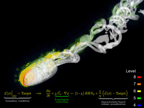
Graphical Abstract

1. Introduction

Numerical simulation of complex geometry flows in a computationally efficient manner represents a challenging problem, especially in the presence of moving/deformable boundaries. Solid bodies are introduced by imposing appropriate boundary conditions upon surfaces, and to that end, several approaches have been developed. These methods can be separated into two major groups: body-fitted mesh [1,2,3] and immersed boundary (IB) methods [4,5,6].
For conventional structured/unstructured body-fitted grid methods, the numerical meshes are conformal to the complex boundaries. Therefore, it is straightforward to impose exact boundary conditions and to attain satisfactory accuracy by employing fine meshes for boundary layers, where high resolutions are required, which is critical for high Reynolds number flows. However, there are some disadvantages to these methods. The grid must be carefully constructed to precisely fit an obstacle. In most cases, this precludes the use of structured Cartesian grids. The process of mesh generation is highly dependent upon the obstacle geometry and can become computationally expensive, especially for complex surfaces. This issue is compounded for moving or deforming obstacles, which require continuous adaptation or re-meshing throughout computation of the solution [6]. The grid generation process may be very expensive: it is not an easy task to generate a good-quality grid, as even simple geometries and simulations for moving boundary problems become prohibitively expensive due to grid generation and solution interpolation to the new mesh at each time step.
The use of IB methods avoids the cost and complications of body meshing by directly introducing the effects of obstacles upon the governing equations. Solid body effects, thus embedded within the flow itself, obviate the rigors of positioning nodes upon a surface. In the IB approach, the boundary conditions on the obstacle surface are indirectly imposed by introducing additional terms in either the discretized [7] or continuous [8] governing equations. In fact, depending on the way the boundary conditions are imposed, IB methods can be roughly grouped into two main classes: discrete [4,7,9,10] and continuous [8,11,12] forcing approaches. Discrete forcing methods are based on modifications of discretized equations, which makes them difficult to generalize due to the direct dependence on methods of discretization. Continuous forcing methods, also referred to as volume penalization (VP) methods, are based on solving modified penalized governing equations, where penalty terms in the form of additional forces (or different feedback mechanisms) ensure the approximation of the boundary conditions. Despite their seeming simplicity and wide use, discrete forcing methods lack generality and flexibility across different solvers and the ability to rigorously control the accuracy of the approximated boundary conditions [6], whereas continuous formulations are independent of the discretization methods and usually have an ability to rigorously control the error of the solution through a penalization parameter [12,13,14]. Since Peskin’s IB method [15] was originally introduced to study flow patterns around heart valves, a number of other IB techniques have been developed for incompressible viscous flows around complex solid boundaries. In contrast to Peskin’s method using external forces to simulate the immersed boundaries, Cartesian grid methods [16,17,18,19] and ghost-cell IB methods [5] directly impose the boundary conditions on the immersed boundaries.
Starting with the work of Arquis & Caltagirone [8] that introduced a VP formulation for incompressible flows around solid obstacles, which is commonly known as the Brinkman penalization (BP) method, considerable efforts have been put into the development of VP methodologies for incompressible flows [12,14,20,21,22]. The main idea of these methods is to model arbitrarily complex solid obstacles as porous media with permeability approaching zero. A principal strength of Brinkman-type penalization, compared to discrete forcing IB methods, is that the error between the solutions of penalized and non-penalized equations can be estimated rigorously in terms of the penalization parameter with the approximate solution converging to the exact one in a predictable fashion [12,13,14,20,23]. Because this VP is simple and cheap to calculate, it is well-suited for flows in complex geometries, including moving obstacles. Much work has been undertaken to refine BP methods for various numerical techniques, including pseudospectral [24,25,26,27], finite-element/finite-volume [28], and wavelet-based [23,29,30,31,32] formulations.
Until recently, most of the effort was put into the development of IB methods for incompressible viscous flows. One of the first attempts at developing a discrete forcing IB method for compressible flows was undertaken in Reference [33], where the flow around a circular cylinder and an airfoil at high Reynolds numbers was modeled. However, the formulation of Ghias et al. [33] did not take into account acoustic wave reflection and transmission at the interface between fluid and solid media, which are critical in some applications with acoustic and shock wave propagation around solid obstacles. Similar problems were observed in the extended impedance mismatch method [34], which extended the original approach of Chung [35] to unsteady non-uniform flow problems.
The Brinkman VP approach was generalized to compressible flows in [36], where in addition to the penalization of momentum and energy equations, the continuity equation was also modified inside the obstacle to be consistent with the porous media flow physics. In the extended compressible BP model, the penalized porous region acts as a high impedance medium, resulting in negligible wave transmissions. As in the incompressible case, the error bounds of the compressible BP method could be rigorously estimated in terms of porosity and permeability parameters. The extended BP method was successfully applied for simulating subsonic compressible flows in both viscous [36] and inviscid [37] conditions.
A number of discrete forcing IB methods have been recently extended to compressible flows as well. The suitability of Cartesian grid methods for modeling compressible high-Reynolds number flows using delayed detached eddy simulation was studied in Reference [38], while sharp-interface [39] and ghost-cell [40,41] IB methods were extended to compressible flows. Moreover, a comparative study of compressible BP and discrete forcing Cartesian grid IB methods was performed in [42] for compressible viscous flows, where an excellent agreement between the two different approaches was observed. It should be noted that, for the compressible BP method, the correct shock reflection was obtained using theoretically predicted values of total energy after shock reflection, as a target in the Brinkman term for the energy equation, which is not known in the general case, and thus should not be used. The imposition of the temperature conditions on the wall results in the incorrect reflection of shock waves, due to creation of a large pressure gradient inside the penalized region and consequent graduate pressure decay due to seepage. This necessitated the development of a more general VP approach capable of approximating compressible flows across all speed regimes, as well as imposing general homogeneous/inhomogeneous Neumann and Robin type boundary conditions. The first step to this end was to develop a characteristic-based volume penalization (CBVP) method [43], where the BP approach was extended to general boundary conditions by introducing hyperbolic VP terms with characteristics pointing inward on solid obstacles. As with the original formulation, CBVP maintains rigorous control of the error, through a priori chosen penalization parameters, for all types of boundary conditions.
The CBVP method was demonstrated for scalar diffusion equations and compressible Navier–Stokes equations for a variety of boundary conditions for both stationary and moving obstacles and was extended to Euler equations [44,45] for stationary obstacles. Lavoie et al. [45] suggested using modified boundary conditions to impose conservation of entropy and total enthalpy in the wall-normal direction instead of adiabatic boundary conditions used in [44], which lead to more accurate results on coarse meshes. However, even though the results of simulation of compressible flows using the compressible BP [36] and CBVP [43] methods were demonstrated to be accurate, as pointed out in Reference [46], mathematically, both formulations were not actually Galilean-invariant. Indeed, Komatsu et al. [46] suggested a Galilean invariant extension of the compressible BP method [36].
In this work, we propose a novel Galilean-invariant extension of the CBVP method to systems of hyperbolic partial differential equations (PDEs) involving moving geometries. This extended formulation, which is referred to as Galilean-invariant characteristic-based volume penalization (GI-CBVP), is demonstrated for supersonic complex geometry flows. The penalized Euler and Navier–Stokes equations are solved for flows around stationary and moving obstacles. It should be noted that the new method is well suited for use with adaptive mesh refinement (AMR) techniques [47]. In fact, the VP approach does not employ body-conformal meshing, and high resolution is required around surfaces for computational accuracy and proper definition of geometry. The use of AMR grids maintains the resolution of solid geometry without over-resolving flow structures. Additionally, the number of nonphysical points lying inside the obstacle can be minimized to those necessary to support the boundary conditions, which is particularly important for obstacles inhabiting a large portion of the computational domain.
All of the results reported in this paper were obtained using the adaptive wavelet collocation (AWC) methodology [48,49,50,51]. AWC represents a general numerical approach that utilizes a wavelet decomposition to dynamically adapt the local mesh resolution on steep gradients in the solution, while retaining a predetermined order of accuracy. Geometry definitions are treated as any other flow variable by AWC methods, where the local grid adapts efficiently and dynamically in order to resolve surfaces, even for moving obstacles. The AWC method was applied to shockless supersonic flows in [52], while a wavelet-based shock capturing scheme was developed to handle flow discontinuities in [53]. The combined VP/AWC approach was undertaken for incompressible flows past stationary obstacles in [54,55]. The interested reader is referred to [56,57] for a complete review of this methodology and its applications.
The rest of the paper is organized as follows. Theoretical and numerical aspects of the new GI-CBVP method are provided in Section 2, while the results of simulations of different benchmark problems are presented and discussed in Section 3. Finally, some conclusions are drawn in Section 4.

2. Characteristic-Based Volume Penalization

2.1. Mathematical Formulation

In the framework of the CBVP approach, the proper boundary conditions are imposed by modifying the governing equations inside the solid region. Consider a compressible flow problem, defined in a physical domain R containing a solid obstacle Ω , and governed (outside of Ω ) by a generalized evolution equation, say
f t = RHS ,
where RHS is simply representing the physical terms on the right hand side of the equation. Note that Equation (1) can be hyperbolic or parabolic in nature. A masking function χ ( x , t ) is defined by
χ ( x , t ) = 1 , if x Ω , t 0 , elsewhere
with Ω standing for the physical domain instantaneously occupied by the solid obstacle. This masking function separates the domain into a physical region and a penalized region associated with the solid obstacle. The general boundary conditions, written in operator form as
L f = Target
are imposed in a similar fashion as BP, namely
f t = 1 χ RHS χ η L f Target .
For Dirichlet type boundary conditions, Equation (4) reduces to BP [12], while homogeneous Neumann type boundary conditions
L f = f n Ω = 0
result in the following penalized equation:
f t = 1 χ RHS χ η f n ,
where f n = n i f x i , with n i representing the components of the inward-oriented surface normal vector. This procedure can be generalized to Robin type boundary conditions, as was demonstrated in Reference [43].
It is important to emphasize that despite the similarity of the different formulations in operator form for Dirichlet, Neumann, and Robin type boundary conditions, the mechanisms underlying each condition are very different. For Dirichlet type boundary conditions, the penalization term acts as a simple feedback mechanism that forces the solution inside the obstacle to the desired target value. For Neumann/Robin type boundary conditions, the solution is convected inside the obstacle along the inward pointing characteristic normal to the surface. In any case, the penalization parameter η determines the timescale of the process. As it was demonstrated in [43], the solutions of the penalized equations for either Dirichlet or Neumann/Robin type penalization converge to the solutions obtained by imposing the exact boundary conditions. Since the penalization timescale is controlled through the parameter η , selecting η 1 causes Equation (4) to become quasi-steady within Ω , on the normalized problem timescale, therefore imposing the intended boundary conditions on the interface. For vanishing η , the increased disparity in timescales asymptotically controls the penalization error. However, reducing the error increases the computational complexity. Since 1 / η is the characteristic velocity for Neumann/Robin type boundary conditions, a reduction of η is also accompanied by increased stiffness, which represents a well-known problem with BP that is mitigated through stiffly-stable solvers [36].
Note that the CBVP method relies on the availability of the normal vector in the entire obstacle interior, that is, where χ = 1 . This normal vector can be either directly prescribed, for simple objects, or constructed through the use of distance or level set functions, defined analytically or numerically, for more complex geometries (e.g., [58]).

2.2. Volume Penalization of Euler Equations

For numerical simulation of the compressible Euler equations, the following boundary conditions at the fluid–obstacle interface are either explicitly assumed or implicitly built into numerical methods (e.g., by constructing ghost cells while using symmetry assumptions) [59]:
u i n Ω = U o i n ( no-penetration condition ) , u i τ n Ω = 0 ( stress free condition ) , p n Ω = κ τ ρ u ^ τ 2 ( no flow separation assumption ) , T n Ω = 0 ( adiabatic wall condition ) ,
where the superscripts ( · ) n and ( · ) τ denote normal and tangential components, respectively. The vector field u ^ = u U o represents the relative to obstacle fluid velocity, with u ^ τ 2 = u ^ j τ u ^ j τ , while κ τ is the streamline surface curvature moving with the obstacle frame of reference. Despite the fact that the only mathematically rigorous boundary condition for Euler equations would be the no-penetration condition, the above boundary conditions are commonly used because they can be derived as outer asymptotic conditions for viscous boundary layer flows. In the present context, these boundary conditions are enforced through the VP approach, as is discussed in the following. For the sake of simplicity, hereafter, the penalized equations are written for the interior of the obstacle, where χ = 1 . Thus, the boundary conditions (6) are enforced as follows:
u i n t = u ^ i η b , u i τ t = 1 η c u i τ n , p t = 1 η c p n + κ τ ρ u ^ τ 2 , T t = 1 η c T n .
Note that in these equations and thereafter, two different parameters η b and η c are used to highlight different asymptotic convergence mechanisms for Brinkman and characteristic-based penalizations, respectively. Also note that, since Equation (7) is defined throughout the obstacle interior, both normal and tangential velocities u n and u τ , as well as the streamline curvature, need to be defined inside the obstacle. This can be achieved by making use of the normal vector field n, so that the different velocity fields are determined as: u n = n i u i n ; u τ = u u n ; u ^ n = n i u ^ i n ; u ^ τ = u ^ u ^ n . As to the streamline curvature, it holds κ τ = τ i τ j n i x j , where τ = u ^ τ u ^ τ represents the unit tangential vector. Using this definition, the pressure equation takes the following simpler form
p t = 1 η c p n ρ u ^ i τ u ^ j τ n i x j .
Therefore, rewriting Equation (7) for conserved variables, using Equation (8) and the total energy definition
E = ρ u i u i 2 + p γ 1 ,
the following evolution equations in the interior of the obstacle are obtained:
ρ t = χ h η c ρ n convective + χ h η c ρ 2 u ^ j τ u ^ k τ p n k x j non-conservative + χ d ν n 2 ρ smoothing , ( ρ u i n ) t = χ η b ρ u ^ i n Brinkman + χ ν n 2 u i n diffusive , ( ρ u i τ ) t = χ h η c ( ρ u i τ ) n convective + χ h η c ρ 2 u i τ u ^ j τ u ^ k τ p n k x j non-conservative + χ d ν n 2 u i τ smoothing , E t = χ h η c E n convective + χ h η c ρ u ^ j τ u ^ k τ γ 1 n k x j + χ h η c u j n ( ρ u j n ) n + χ h u j n ν n 2 u j n χ h η b ρ u j n u ^ j n non-conservative + χ d ν n 2 E smoothing ,
where 2 ( · ) stands for the Laplacian differential operator.
In these equations, the diffusive and smoothing terms, in addition to convective, Brinkman, and non-conservative forcing terms, are considered in order to stabilize the numerical implementation. Note that the convective terms practically correspond to the CBVP approach. In particular, the Brinkman term in the normal momentum equation is complemented by the diffusive term, which is added to control spatial resolution of the inner boundary layer for a given mesh size Δ , and penalization parameter η b , and to avoid spurious oscillations at the boundary. The corresponding numerical viscosity ν n = α 2 Δ 2 / η b (with α = O ( 1 ) ) is chosen to guarantee that the diffusion in the interior of the obstacle is occurring on the same timescale as η b . For more details on the diffusion term determination, the reader is referred to Reference [43].
It should be emphasized that the application of convective terms in the entire interior domain of the obstacle is undesirable for two reasons: (i) normal vectors are ill-defined far from boundaries, due to possible intersection of the characteristics and existence of extrema points in the distance function, (ii) an additional computational cost and deterioration of stability/accuracy of characteristic equations far from the boundaries. For these reasons, the characteristic equations are only solved in a narrow internal layer close to the obstacle boundary, denoted by masking function χ h , which is just wide enough to propagate the solution along characteristics within the actual stencil of the differential operator. As a result, all convective and non-conservative terms in Equation (10) are only present in this layer. Differently, the BP and corresponding penalization terms are applied throughout the entire region defined by obstacle masking function χ . Since the characteristics are pointed inwards, the solution of Euler equations in the fluid region and in the thin layer defined by masking function χ h are not affected by the solution in the remaining interior region of the obstacle, denoted by masking function χ d . Note that the masking functions χ h and χ d are orthogonal, i.e., χ = χ h + χ d . The convective terms are complemented by smoothing terms using the same form as diffusive terms but defined only in the region of the masking function χ d . The schematic illustration of different masking functions and regions where they are defined is given in Figure 1.
Finally, when the Euler equations are solved together with Equation (10) for the penalized region, the penalization terms for evolution of normal and tangential momentums are combined according to
( ρ u i ) t = ( ρ u i n ) t + ( ρ u i τ ) t ,
resulting in the simultaneous enforcement of boundary conditions at the surface for both normal and tangential velocity components.

2.3. Volume Penalization of Navier–Stokes Equations

The penalization approach introduced in the previous section is also applicable to the Navier–Stokes equations for problems with adiabatic walls. Since the form of no-slip boundary conditions is mathematically equivalent to the form of no-penetration boundary conditions, Equation (10) is directly applicable for the penalization of the Navier–Stokes equations after performing the following substitutions: u n u , u τ 0 , and U o n U o . In other words, the penalization equation for the tangential velocity component is simply ignored. For the solution of the Navier–Stokes equations with non-zero heat flux, the adiabatic wall boundary conditions (6) need to be replaced by
T n Ω = q ,
where q is the normalized heat flux. The latter variable can be either prescribed or expressed as a function of the wall temperature. The penalization equation for the temperature in the system (7) can be modified following the procedure given by Equation (4).

2.4. Moving Obstacles

When solving flows with moving boundaries, it is important that the underlying problem (governing equations and associated boundary conditions) is invariant with respect to a change of the reference frame, which is commonly referred to as Galilean invariance. In this case, the solution of the fluid flow equations should be the same in every inertial frame. Unfortunately, while boundary conditions (6) are Galilean-invariant, the system of penalized Equation (10) is not. In order to become Galilean-invariant, these equations need to be reformulated in the reference frame moving with the obstacle velocity and then transformed for the stationary frame. This procedure results in adding Lagrangian terms to the equations, according to the following transformation: t t + U j o x j . To theoretically demonstrate the Galilean invariance of the proposed formulation let us consider the Galilean-invariant formulation of Equation (4) enforcing the boundary condition (3) on the boundary of the obstacle moving with velocity U o
f t + χ o x U o t U j o f x j = ( 1 χ o x U o t ) RHS χ o x U o t η ( L f Target ) ,
where the masking function for the moving obstacle is explicitly written as
χ ( x , t ) = χ o x U o t .
Assuming that the RHS is Galilean-invariant outside of the obstacle, the formulation (13) is Galilean-invariant for general boundary condition, including the Dirichlet boundary condition on the velocity, which follows from the Galilean invariance of spatial operators, Dirichlet boundary conditions of non-velocity variables, and the relative velocity u ^ = u U o used in either no-slip or no-penetration boundary conditions. Thus, the proposed extension of a characteristic-based volume penalization method is Galilean-invariant on the formulation level.
This way, the system of penalized Equation (7) in the interior of the obstacle is rewritten as
u i n t + U j o u i n x j = u ^ i , η b u i τ t + U j o u i τ x j = 1 η c u i τ n , p t + U j o p x j = 1 η c p n + κ τ ρ u ^ τ 2 , T t + U j o T x j = 1 η c T n .
Analogously, the system of penalized evolution Equation (10) in the interior of the obstacle becomes
ρ t + χ U j o ρ x j = χ h η c ρ n convective + χ h η c ρ 2 u ^ j τ u ^ k τ p n k x j non-conservative + χ d ν n 2 ρ smoothing , ( ρ u i n ) t + χ U j o ( ρ u i n ) x j = χ η b ρ u ^ i n Brinkman + χ ν n 2 u i n diffusive , ( ρ u i τ ) t + χ U j o ( ρ u i τ ) x j = χ h η c ( ρ u i τ ) n convective + χ h η c ρ 2 u i τ u ^ j τ u ^ k τ p n k x j non-conservative + χ d ν n 2 u i τ smoothing , E t + χ U j o E x j = χ h η c E n convective + χ h η c ρ u ^ j τ u ^ k τ γ 1 n k x j + χ h η c u j n ( ρ u j n ) n + χ h u j n ν n 2 u j n χ h η b ρ u j n u ^ j n non-conservative + χ d ν n 2 E smoothing ,
where the Lagrangian terms are explicitly multiplied by masking function χ to emphasize that they are applied throughout the entire obstacle.
It is worth noting that the original formulation of the CBVP method for moving obstacles, in the context of compressible Navier–Stokes equations [43], did not involve any Lagrangian terms, without affecting the accuracy of the results. The reason for this weak sensitivity to the presence of these additional terms was the use of no-slip boundary conditions and smooth variation of the solution in the vicinity of the solid boundary. In fact, the correct boundary conditions were simply achieved through the BP term, which adjusted the solution on the timescale of η b . The situation is drastically different for the Euler equations, since the changes in the tangential velocity field can be substantial if the solution inside the obstacle is not convected with the obstacle velocity. The results of the numerical experiments, which are reported in Section 3.4, confirm higher accuracy and better convergence of the new GI-CBVP formulation (16). The use of Lagrangian terms in the penalized equations is, however, recommended for both Euler and Navier–Stokes approaches.
Finally, due to the local nature of the penalized equations, the proposed formulation is also applicable for rotating and deformable objects, in addition to obstacles with translational motions. In the former case, the obstacle velocity at every interior point needs to be provided, either analytically or through the solution of a governing equation for the evolution of the obstacle motion or its deformation.

2.5. Adaptive Wavelet Collocation Method

The AWC method utilizes the wavelet-based decomposition of the flow field unknowns to dynamically adapt the local mesh resolution on steep gradients in the solution, while retaining a predetermined order of accuracy [29,48,49]. Formally, a scalar spatial field f ( x ) can be represented in terms of wavelet basis functions as
f ( x ) = l L 0 c l 0 ϕ l 0 ( x ) + j = 0 + μ = 1 2 3 1 k K μ , j d k μ , j ψ k μ , j ( x ) ,
where ϕ l 0 and ψ k μ , j are three-dimensional scaling functions and wavelets of different families ( μ ) and levels of resolution (j), respectively. The above wavelet decomposition can be thought as of a multi-resolution representation of f, where each level of resolution consists of a family of wavelets ψ k μ , j having the same scale but located at different positions.
In order to compress the numerical solution, wavelet filtering is performed through wavelet coefficient thresholding. Given the number of resolution levels, say j m a x , the wavelet filtered variable is defined by
f ¯ > ϵ ( x ) = l L 0 c l 0 ϕ l 0 ( x ) + j = 0 j m a x μ = 1 2 3 1 | d k μ , j | > ϵ f k K μ , j d k μ , j ψ k μ , j ( x ) ,
where ϵ stands for the non-dimensional threshold to be prescribed. A good approximation of the unfiltered field can be retained even after discarding a large number of wavelets with small coefficients, because the coefficients d k μ , j are small unless f causes a significant variation on the level of resolution j, in the immediate vicinity of the wavelet ψ k μ , j location. The reconstruction error was demonstrated to converge as
f ¯ > ϵ f C ϵ f ,
with C = O ( 1 ) . Due to the one-to-one correspondence between wavelets and collocation points, the nodes are omitted from the computational mesh if the associated wavelets are excluded from the truncated approximation (18). Thus, the multilevel structure of the wavelet approximation provides a natural way to obtain the solution on a nearly optimal numerical mesh, which is dynamically adapted to the evolution of the main flow structures, both in location and scale. The multi-resolution wavelet decomposition (18) is used for both mesh adaptation and interpolation, while the derivatives at the adaptive computational nodes are found by differentiation of the local wavelet interpolant at the appropriate level of resolution. In addition, for supersonic flows, the AWC method is supplemented with a shock capturing scheme [53], which uses wavelet coefficients to define local numerical viscosity in the neighborhood of the shock waves and to automatically switch it off away from them.

3. Numerical Results and Discussion

The original CBVP method was already demonstrated for a number of problems with smooth solutions, such as heat equation, acoustic wave reflection, and low Mach compressible viscous flow around a two-dimensional cylinder [43]. The present study focuses on evaluating the novel aspects of the extended method that is developed for solving systems of hyperbolic PDEs with discontinuous solutions, in the presence of stationary or moving obstacles of arbitrary complexity. For that purpose, a number of different benchmark tests are performed. Specifically, the first test is represented by the one-dimensional shock tube problem, where the shock reflection from the wall is quantitively evaluated, with the wall being approximated by the GI-CBVP method. The second and third benchmark problems test the ability of the new method to correctly model the effect of the obstacle for the generation of oblique and detached shock waves, while the fourth test demonstrates the Galilean invariance of the GI-CBVP approach. In addition, the two-dimensional benchmark problems illustrate the efficiency of using the adaptive wavelet-based mesh refinement with the GI-CBVP method and the ability of the integrated approach to adequately resolve the obstacle geometry without over-resolving flow structures and minimizing the number of grid points inside the solid obstacles.

3.1. Benchmark I: Normal Shock Wave Reflection

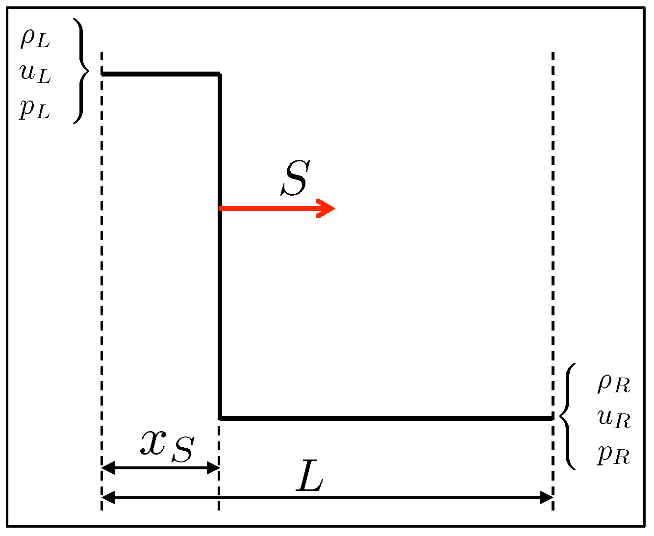
Let us consider the one-dimensional Sod’s (shock tube) test problem in the spatial domain R = [ 0.5 , 1.5 ] , where the wall is prescribed as a volumetric obstacle occupying the region Ω = [ 1 , 1.5 ] , and the shock is initially located at x 0 = 0 . The initial states in front and behind the shock are chosen according to the Rankine–Hugoniot jump conditions. Practically, after prescribing the post-shock conditions ρ L = 1 , u L = 2 and p L = 1 , as well as u R = 0 , the pre-shock conditions ρ R and p R , as well as the shock velocity S, are found according to the given jump conditions. The schematic diagram of this problem is reported in Figure 2, where x S represents the shock location and L stands for the length of the computational domain.
Different calculations are conducted for a series of uniformly spaced, non-adaptive computational meshes consisting of a number of grid points N between 2 9 and 2 13 . Pressure seepage and amplitude error are significantly reduced when compared to the results obtained with the compressible BP method [36], but a phase lag is still present. In Figure 3, local pressure plots at the end of the simulation, when the reflected shock front is far from the wall, are presented for coarse and fine mesh resolutions, with the penalization coefficients being set to the values of η c = 10 3 and η b = 10 5 .
The penalty parameters determine the transition time of the shock wave reflection from the wall, while the spatial discretization size Δ x determines the shock thickness, with all three parameters contributing to the phase lag. In fact, the characteristic timescale of the finite width shock wave reflection from the solid wall is τ swr = S / Δ x , while the timescale of the transitional effects due to the penalization procedure is τ η = max η b , η c . Taking into account the different rates of convergence for Brinkman and CBVP methods that are, respectively, O ( η b 1 / 2 ) and O ( η c ) [43], the BP parameter is constrained as η b = η c 2 , for a given value of η c . Results of parametric sweep for η c 10 3 , 10 1 , corresponding to four different grid resolutions, are provided in Figure 4. One can see that, as long as the penalization transitional timescale is shorter than the shock reflection timescale, τ η < τ swr , the numerical discretization error associated with finite width shock readjustment is dominating. For the opposite case, when τ η > τ swr , the error converges linearly as O ( η c ) .

3.2. Benchmark II: Oblique Shock Wave

In order to demonstrate the ability of the proposed methodology to correctly capture both oblique and detached shock wave reflections, supersonic inviscid flow past wedges with subcritical and supercritical wedge angles are simulated. The presence of the wedge is modeled, employing the GI-CBVP methodology. The incident shock wave conditions are chosen to be the same as in the previous benchmark problem, namely, u L = 1.6 , p L = 1 , ρ L = 1 , u R = 0 and ρ R , p R and S corresponding to the Rankine–Hugoniot jump conditions. The two-dimensional computational domain is R = [ 0.5 , 1.5 ] × [ 0 , 4 ] and the wedge apex is located at the point ( 0.28 , 0 ) . The AWC method [48], supplied with the shock capturing scheme [53], with the effective mesh resolution of 513 × 1025 points and eight levels of resolution, is used for this test. Inflow boundary conditions are applied on the left boundary with values equal to the left shock state values. On the top boundary, and on the portion of the bottom boundary located before the wedge, symmetry boundary conditions are used. Outflow boundary conditions are imposed on the right boundary, outside of the wedge. Moreover, tangential diffusion boundary conditions are used on the wedge domain boundaries.
For subcritical flow, the angle of the reflected shock is given analytically by the following relation
tan θ = 2 cot β Ma 2 sin 2 β 1 Ma 2 γ + cos 2 β + 2 ,
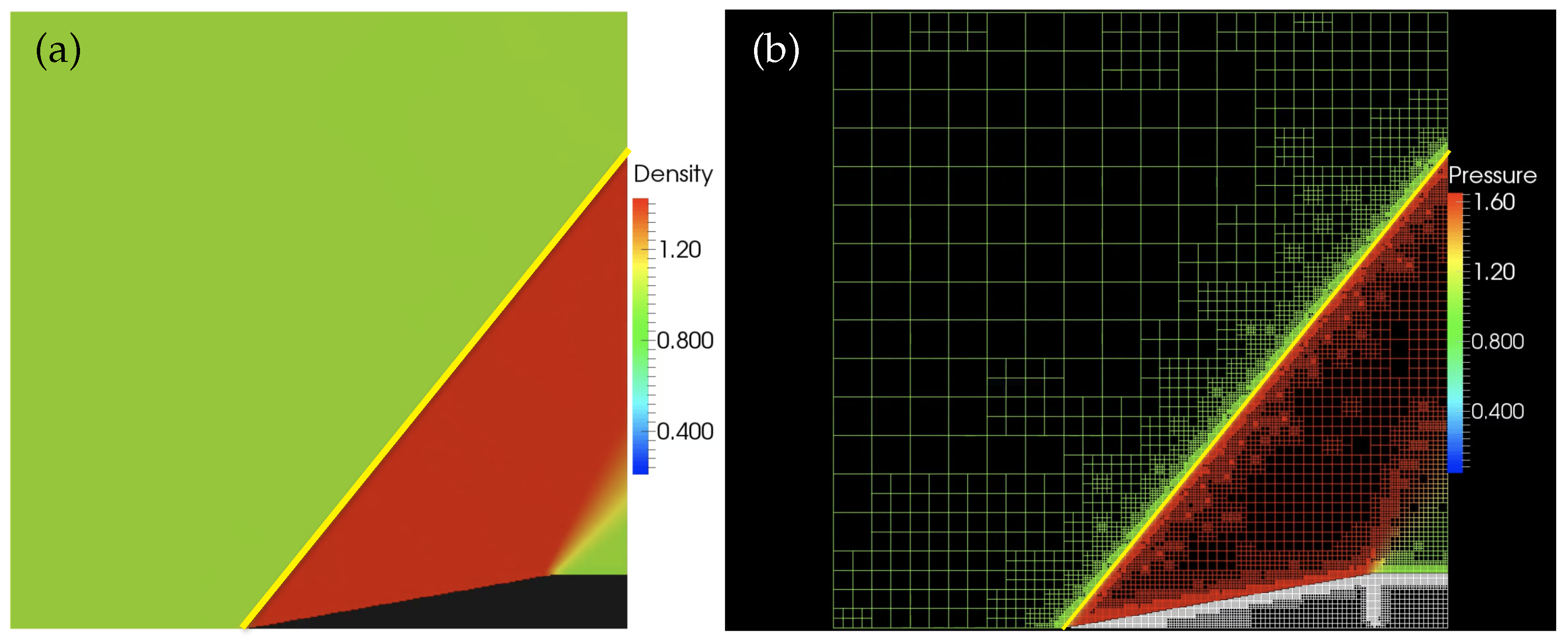
where θ is the wedge angle, β is the deflected shock angle, and Ma is the Mach number of the incident shock wave. The inviscid supersonic flow past a wedge with the deflection angle of θ = 10 is simulated. The solution of the problem is shown in Figure 5a with the object geometry displayed in black. The adaptive computation mesh, demonstrating the adaptive resolution of solid surfaces and shock structures, is demonstrated in Figure 5b. The attached oblique shock wave with the oblique angle of β 51 is illustrated in Figure 5a,b by the yellow line, with the theoretical value of β = 51 . 1 being predicted by Equation (20) with Ma = 1.6 . The adaptive computation mesh, demonstrating the adaptive resolution of solid surfaces and shock structures is shown in Figure 5b. It is worth noting the presence of the fine local mesh inside of the obstacle at the expansion corner, which is caused by ill-defined normal vectors.

3.3. Benchmark III: Two-Dimensional Supersonic Flows around Blunt Bodies

In order to demonstrate the ability of the proposed GI-CBVP method to approximate the supersonic flows around stationary blunt bodies and the efficiency of the adaptive wavelet-based mesh refinement to adequately resolve the geometry, while minimizing the number of grid points inside the solid obstacle, unsteady simulations of two-dimensional inviscid flows around multiple circular cylinders are performed. The inflow parameters are the same as in Section 3.2. The computational domain for the supersonic inviscid flow around an array of randomly placed cylinders of radius r = 0.5 in the domain R = [ 4 , 4 ] × [ 4 , 4 ] is considered. Inflow boundary conditions are applied on the left boundary with values equal to the left shock state values. Outflow boundary conditions are used for the right boundary, while periodic boundary conditions in the vertical direction are assumed.
The AWC method [48] supplied with a shock capturing scheme [53], with the effective mesh resolution of 1025 × 1025 and eight levels of resolution, is used for the problem. The penalized Euler equations are solved with the obstacle geometry approximated by the GI-CBVP methodology (10).
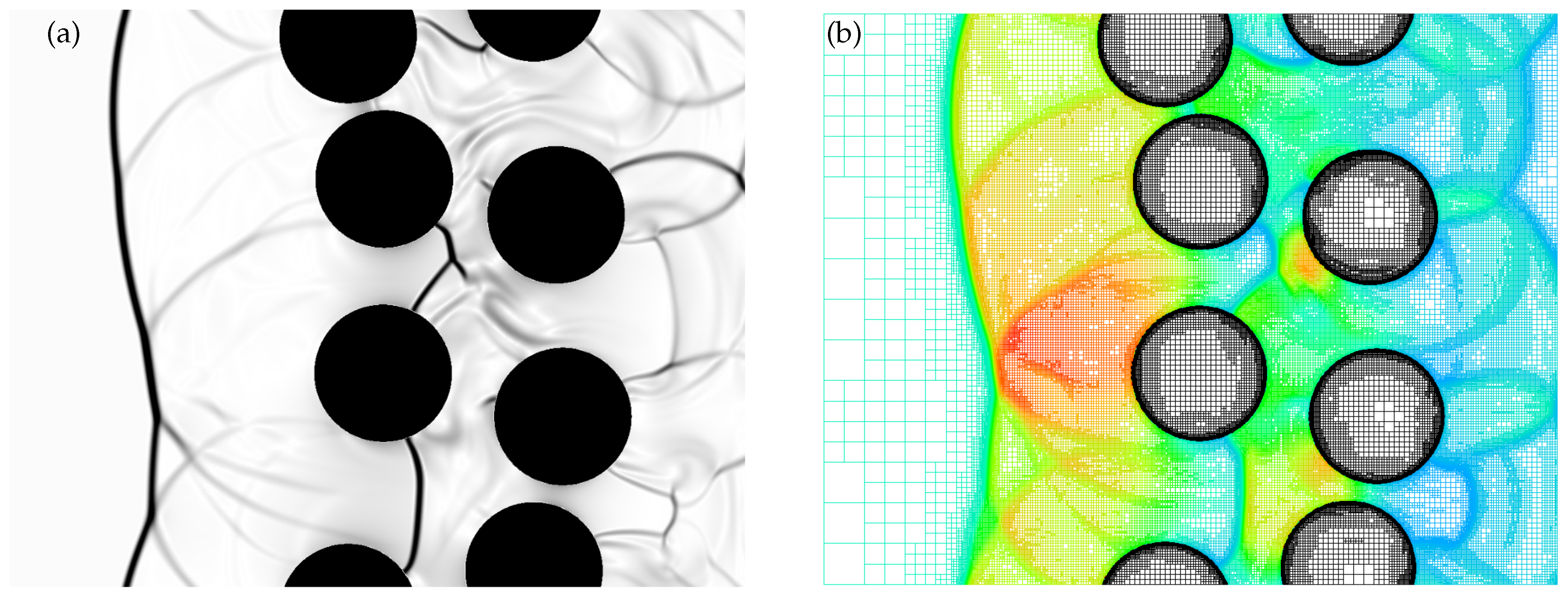
Results of the unsteady AWC simulation with the GI-CBVP method of the flow around an array of randomly placed cylinders are presented in Figure 6, where the instantaneous solution is examined in terms of the numerical schlieren image and corresponding adaptive computational mesh colored by the pressure field. These results illustrate the ability of the proposed method to effectively represent more complicated flow geometry and highlight the advantages of using the GI-CBVP method in combination with wavelet-based AMR. The use of the AWC methodology allows for the efficient resolution of solid surfaces and shock structures, while minimizing the computational costs of the simulation.

3.4. Benchmark IV: Galilean Invariance

In order to illustrate the Lagrangian modification introduced for moving obstacles in Section 2.4 and demonstrate the conformity with Galilean invariance, two additional simulations using the modified governing Equation (16) are performed. Both simulations are conducted in the computational domain R = [ 0 , 6 ] × [ 0 , 2 ] . In the first simulation, uniform flow with velocity 1.5 Ma past a fixed solid cylinder of radius r = 0.2 is considered. In the second simulation, a solid cylinder of the same radius is moving with the non-dimensional velocity U x o = 1.5 Ma in still fluid. Inflow boundary conditions are applied on the left boundary, while outflow boundary conditions are used for the right boundary. Symmetry boundary conditions are applied on top and bottom boundaries. In Figure 7, the initial setup and snapshot of the density and pressure fields at both the beginning and the end of the two simulations are provided. These simulations were run until the second cylinder reached the same location as the first one. Apparently, resolved fields and underlying adaptive grids are the same, with only minuscule discrepancies in the wake region, associated with different instability triggering for stationary and moving cylinders.
The proven computational Galilean invariance is important, since mathematical (in terms of governing equations) and physical (in terms of inertial frames of reference) equivalence of the simulations were not guaranteed numerically by the original CBVP method [43] without proper modifications. In fact, the results of the numerical simulation of the moving cylinder without the Lagrangian correction term (not presented here) demonstrated a significant loss of accuracy as well as slow convergence of boundary conditions to target values.

4. Conclusions

This work originally extends the characteristic-based volume penalization method to a hyperbolic system of PDEs that governs compressible flows with moving complex geometries. The proposed methodology results in being general, Galilean-invariant, and allowing the imposition of homogeneous and inhomogeneous Dirichlet, Neumann and Robin type boundary conditions. Both stationary and moving geometries can be treated, where the approximation error is defined a priori, being controlled by the penalization parameters. The method permits the generic formulation of boundary conditions for both integrated and non-integrated variables in a systematic manner that parallels the prescription of exact boundary conditions.
The novel approach is demonstrated to be applicable to both Euler and Navier–Stokes equations across all speed regimes. The proper approximation of boundary conditions for moving geometries is achieved by means of the inclusion of Lagrangian terms into the penalized equations, which makes the formulation Galilean-invariant and increases both stability and accuracy of the methodology, especially in the context of Euler equations, where tangential velocity is not continuous across the fluid–solid interface. Moreover, the proposed methodology is demonstrated to be well suited for use in conjunction with wavelet-based adaptive mesh refinement methods. This is particularly notable in the case of moving obstacles, where transients can be exploited to optimize the computational cost of the simulations.

Author Contributions

Data curation, N.K. and O.V.V.; investigation, N.K. and O.V.V.; methodology, N.K, E.D., and O.V.V.; resources, G.D. and O.V.V.; supervision, O.V.V.; validation, N.K. and O.V.V.; visualization, N.K.; writing, original draft preparation, N.K., G.D. and O.V.V.; writing, review and editing, G.D. and O.V.V. All authors read and agreed to the published version of the manuscript.

Funding

This research received no external funding.

Conflicts of Interest

The authors declare no conflict of interest.

Abbreviations

The following abbreviations are used in this manuscript:
AMRadaptive mesh refinement
AWCadaptive wavelet collocation
BPBrinkman penalization
CBVPcharacteristic-based volume penalization
GI-CBVPGalilean-invariant characteristic-based volume penalization
IBimmersed boundary
PDEspartial differential equations
VPvolume penalization

References

  1. Thompson, J.F.; Warsi, Z.U.A.; Mastin, C.W. Boundary fitted coordinate systems for numerical solution of partial differential equations—A review. J. Comput. Phys. 1982, 47, 1–108. [Google Scholar] [CrossRef]
  2. Thomas, P.D.; Middlecoff, J.F. Direct control of the grid point distribution in meshes generated by elliptic equations. AIAA J. 1980, 18, 652–656. [Google Scholar] [CrossRef]
  3. Kaul, U.K. Three-dimensional elliptic grid generation with fully automatic boundary constraints. J. Comput. Phys. 2010, 229, 5966–5979. [Google Scholar] [CrossRef]
  4. Peskin, C.S. The immersed boundary method. Acta Numer. 2002, 11, 479–517. [Google Scholar] [CrossRef] [Green Version]
  5. Tseng, Y.H.; Ferziger, J.H. A ghost-cell immersed boundary method for flow in complex geometry. J. Comput. Phys. 2003, 192, 593–623. [Google Scholar] [CrossRef]
  6. Mittal, R.; Iaccarino, G. Immersed boundary methods. Annu. Rev. Fluid Mech. 2005, 37, 239–261. [Google Scholar] [CrossRef] [Green Version]
  7. Fadlun, E.A.; Verzicco, R.; Orlandi, P.; Mohd-Yusof, J. Combined immersed-boundary finite-difference methods for three-dimensional complex flow simulations. J. Comput. Phys. 2000, 161, 35–60. [Google Scholar] [CrossRef]
  8. Arquis, E.; Caltagirone, J.P. Sur les conditions hydrodynamiques au voisinage d’une interface milieu fluide-milieu poreux: Application à la convection naturelle. CR Acad. Sci. Paris II 1984, 299, 1–4. [Google Scholar]
  9. Lai, M.C.; Peskin, C.S. An immersed boundary method with formal second order accuracy and reduced numerical viscosity. J. Comput. Phys. 2000, 160, 705–719. [Google Scholar] [CrossRef] [Green Version]
  10. Saiki, E.M.; Biringen, S. Numerical simulation of a cylinder in uniform flow: Application of a virtual boundary method. J. Comput. Phys. 1996, 123, 450–465. [Google Scholar] [CrossRef]
  11. Goldstein, D.; Handler, R.; Sirovich, L. Modeling a no-slip flow boundary with an external force field. J. Comput. Phys. 1993, 105, 354–366. [Google Scholar] [CrossRef] [Green Version]
  12. Angot, P.; Bruneau, C.; Fabrie, P. A penalization method to take into account obstacles in viscous flows. Numer. Math. 1999, 81, 497–520. [Google Scholar] [CrossRef]
  13. Feireisl, E.; Neustupa, J.; Stebel, S. Convergence of a Brinkman-type penalization for compressible fluid flows. J. Differ. Equ. 2011, 250, 596–606. [Google Scholar] [CrossRef] [Green Version]
  14. Carbou, G.; Fabrie, P. Boundary layer for a penalization method for viscous incompressible flow. Adv. Differ. Equ. 2003, 8, 1453–1480. [Google Scholar]
  15. Peskin, C.S. Flow Patterns around Heart Valves: A Digital Computer Method for Solving the Equations of Motion. Ph.D. Thesis, Albert Einstein College of Medicine, New York, NY, USA, 1972. [Google Scholar]
  16. Purvis, J.W.; Burkhalter, J.E. Prediction of critical mach number for store configurations. AIAA J. 1979, 17, 1170–1177. [Google Scholar] [CrossRef]
  17. Clarke, D.K.; Salas, M.D.; Hassen, H.A. Euler calculations for multielement airfoils using cartesian grids. AIAA J. 1986, 24, 353–358. [Google Scholar] [CrossRef]
  18. Zeeuw, D.D.; Powell, K.G. An adaptively refined cartesian mesh solver for the Euler equations. J. Comput. Phys. 1993, 104, 56–68. [Google Scholar] [CrossRef] [Green Version]
  19. Berger, M.J.; Aftosmis, M.J. Aspects (and aspect ratios) of cartesian mesh methods. In Proceedings of the Sixteenth International Conference on Numerical Methods in Fluid Dynamics, Arcachon, France, 6–10 July 1998. [Google Scholar]
  20. Khadra, K.; Angot, P.; Parneix, S.; Caltagirone, J.P. Fictitious domain approach for numerical modelling of Navier-Stokes equations. Int. J. Numer. Methods Fluids 2000, 34, 651–684. [Google Scholar] [CrossRef]
  21. Kevlahan, N.R.; Ghidaglia, J.M. Computation of turbulent flow past an array of cylinders using a spectral method with Brinkman Penalization. Eur. J. Mech. B Fluids 2001, 20, 333–350. [Google Scholar] [CrossRef] [Green Version]
  22. Reckinger, S.; Vasilyev, O.V.; Fox-Kemper, B. Adaptive Volume Penalization for Ocean Modeling. Ocean Dyn. 2012, 62, 1201–1215. [Google Scholar] [CrossRef]
  23. Kevlahan, N.K.R.; Vasilyev, O.V. An adaptive wavelet collocation method for fluid-structure interaction at high Reynolds numbers. SIAM J. Sci. Comput. 2005, 26, 1894–1915. [Google Scholar] [CrossRef] [Green Version]
  24. Pasquetti, R.; Bwemba, R.; Cousin, L. A pseudo-penalization method for high Reynolds number unsteady flows. Appl. Numer. Math. 2007, 58, 946–954. [Google Scholar] [CrossRef]
  25. Jause-Labert, C.; Godeferd, F.; Favier, B. Numerical validation of the volume penalization method in three-dimensional pseudo-spectral simulations. Comput. Fluids 2012, 67, 41–56. [Google Scholar] [CrossRef]
  26. Kolomenskiy, D.; Schneider, K. A Fourier spectral method for the Navier–Stokes equations with volume penalization for moving solid obstacles. J. Comput. Phys. 2009, 228, 5687–5709. [Google Scholar] [CrossRef]
  27. Engels, T.; Kolomenskiy, D.; Schneider, K.; Sesterhenn, J. FluSI: A novel parallel simulation tool for flapping insect flight using a Fourier method with volume penalization. SIAM J. Sci. Comput. 2016, 38, S3–S24. [Google Scholar] [CrossRef] [Green Version]
  28. Ramière, I.; Angot, P.; Belliard, M. A fictitious domain approach with spread interface for elliptic problems with general boundary conditions. Comput. Methods Appl. Mech. Eng. 2007, 196, 766–781. [Google Scholar] [CrossRef] [Green Version]
  29. Vasilyev, O.V.; Kevlahan, N.K.R. Hybrid Wavelet Collocation-Brinkman Penalization Method for Complex Geometry Flows. Int. J. Numer. Methods Fluids 2002, 40, 531–538. [Google Scholar] [CrossRef]
  30. Schneider, K.; Farge, M. Adaptive wavelet simulation of a flow around an impulsively started cylinder using penalisation. Appl. Comput. Harmon. Anal. 2002, 12, 374–380. [Google Scholar] [CrossRef] [Green Version]
  31. Wirasaet, D.; Paolucci, S. Adaptive wavelet method for incompressible flows in complex domains. J. Fluids Eng. 2005, 127, 656–665. [Google Scholar] [CrossRef]
  32. Keetels, G.H.; D’Ortona, U.; Kramer, W.; Clercx, H.J.H.; Schneider, K.; Van Heijst, G.J.F. Fourier spectral and wavelet solvers for the incompressible Navier-Stokes equations with volume-penalization: Convergence of a dipole-wall collision. J. Comput. Phys. 2007, 227, 919–945. [Google Scholar] [CrossRef]
  33. Ghias, R.; Mittal, R.; Lund, T.S. A non-body conformal grid method for simulation of compressible flows with complex immersed boundaries. In Proceedings of the 42nd AIAA Aerospace Sciences Meeting and Exhibit, Reno, NV, USA, 5–8 January 2004. [Google Scholar]
  34. Cohen, R.; Ooi, A.; Iaccarono, G. Towards the application of the impedance mismatch method to the expansion about incompressible flow acoustic equations. In Proceedings of the Summer Program 2006, Kiten, Bulgaria, 3–9 July 2006. [Google Scholar]
  35. Chung, C. Wave Propagation and Scattering in Computational Aeroacoustics. Ph.D. Dissertation, Department of Aerospace Engineering, Pennsylvania State University, University Park, PA, USA, 1995. [Google Scholar]
  36. Liu, Q.; Vasilyev, O.V. A Brinkman penalization method for compressible flows in complex geometries. J. Comput. Phys. 2007, 227, 946–966. [Google Scholar] [CrossRef]
  37. Bae, Y.; Moon, Y. On the use of Brinkman Penalization Method for computation of acoustic scattering from complex boundaries. Comput. Fluids 2012, 55, 48–56. [Google Scholar] [CrossRef]
  38. Bernardini, M.; Modesti, D.; Pirozzoli, S. On the suitability of the immersed boundary method for the simulation of high-Reynolds-number separated turbulent flows. Comput. Fluids 2016, 130, 84–93. [Google Scholar] [CrossRef]
  39. De Vanna, F.; Picano, F.; Benini, E. A sharp-interface immersed boundary method for moving objects in compressible viscous flows. Comput. Fluids 2020, 201, 104415. [Google Scholar] [CrossRef]
  40. Ehsan Khalili, M.; Larsson, M.; Müller, B. Immersed boundary method for viscous compressible flows around moving bodies. Comput. Fluids 2018, 170, 77–92. [Google Scholar] [CrossRef]
  41. Boukharfane, R.; Ribeiro, F.; Bouali, Z.; Mura, A. A combined ghost-point-forcing / direct-forcing immersed boundary method (IBM) for compressible flow simulations. Comput. Fluids 2018, 162, 91–112. [Google Scholar] [CrossRef]
  42. Piquet, A.; Roussel, O.; Hadjadj, A. A comparative study of Brinkman penalization and direct-forcing immersed boundary methods for compressible viscous flows. Comput. Fluids 2016, 136, 272–284. [Google Scholar] [CrossRef]
  43. Brown-Dymkoski, E.; Kasimov, N.; Vasilyev, O.V. A characteristic based volume penalization method for general evolution problems applied to compressible viscous flows. J. Comput. Phys. 2014, 262, 344–357. [Google Scholar] [CrossRef] [Green Version]
  44. Brown-Dymkoski, E.; Kasimov, N.; Vasilyev, O.V. Characteristic-based volume penalization method for arbitrary Mach flows around solid obstacles. In Direct and Large-Eddy Simulation IX; Frohlich, J., Kuerten, H., Geurts, B., Armenio, V., Eds.; ERCOFTAC Series; Springer: Berlin/Heidelberg, Germany, 2015; pp. 109–115. [Google Scholar]
  45. Lavoie, P.; Radenac, E.; Blanchard, G.; Laurendeau, É.; Villedieu, P. An improved characteristic based volume penalization method for the Euler equations towards icing applications. Comput. Fluids 2021, 222. [Google Scholar] [CrossRef]
  46. Komatsu, R.; Iwakami, W.; Hattori, Y. Direct numerical simulation of aeroacoustic sound by volume penalization method. Comput. Fluids 2016, 130, 24–36. [Google Scholar] [CrossRef]
  47. Thompson, J.F.; Soni, B.K.; Weatherill, N.P. (Eds.) Handbook of Grid Generation; CRC Press: Boca Raton, FL, USA; London, UK; New York, NY, USA, 1999. [Google Scholar]
  48. Vasilyev, O.V.; Bowman, C. Second-Generation Wavelet Collocation Method for the Solution of Partial Differential Equations. J. Comput. Phys. 2000, 165, 660–693. [Google Scholar] [CrossRef] [Green Version]
  49. Vasilyev, O.V. Solving Multi-Dimensional Evolution Problems with Localized Structures Using Second Generation Wavelets. Int. J. Comput. Fluid Dyn. 2003, 17, 151–168. [Google Scholar] [CrossRef]
  50. Vasilyev, O.V.; Kevlahan, N.K.R. An adaptive multilevel wavelet collocation method for elliptic problems. J. Comput. Phys. 2005, 206, 412–431. [Google Scholar] [CrossRef] [Green Version]
  51. Nejadmalayeri, A.; Vezolainen, A.; Brown-Dymkoski, E.; Vasilyev, O.V. Parallel Adaptive Wavelet Collocation Method for PDEs. J. Comput. Phys. 2015, 298, 237–253. [Google Scholar] [CrossRef] [Green Version]
  52. De Stefano, G.; Brown-Dymkoski, E.; Vasilyev, O.V. Wavelet-based adaptive large-eddy simulation of supersonic channel flow. J. Fluid Mech. 2020, 901, A13. [Google Scholar] [CrossRef]
  53. Regele, J.; Vasilyev, O.V. An adaptive wavelet-collocation method for shock computations. Int. J. Comput. Fluid Dyn. 2009, 23, 503–518. [Google Scholar] [CrossRef]
  54. De Stefano, G.; Vasilyev, O.V. Wavelet-based adaptive simulations of three-dimensional flow past a square cylinder. J. Fluid Mech. 2014, 748, 433–456. [Google Scholar] [CrossRef] [Green Version]
  55. De Stefano, G.; Nejadmalayeri, A.; Vasilyev, O.V. Wall-resolved wavelet-based adaptive large-eddy simulation of bluff-body flows with variable thresholding. J. Fluid Mech. 2016, 788, 303–336. [Google Scholar] [CrossRef]
  56. Schneider, K.; Vasilyev, O.V. Wavelet methods in computational fluid dynamics. Annu. Rev. Fluid Mech. 2010, 42, 473–503. [Google Scholar] [CrossRef] [Green Version]
  57. De Stefano, G.; Vasilyev, O.V. Hierarchical adaptive eddy-capturing approach for modeling and simulation of turbulent flows. Fluids 2021, 6, 83. [Google Scholar] [CrossRef]
  58. Sethian, J.A. Level Set Methods; Cambridge University Press: Cambridge, UK, 1996. [Google Scholar]
  59. Toro, E. Riemann Solvers and Numerical Methods for Fluid Dynamics: A Practical Introduction, 3rd ed.; Springer: Berlin/Heidelberg, Germany, 2009. [Google Scholar]
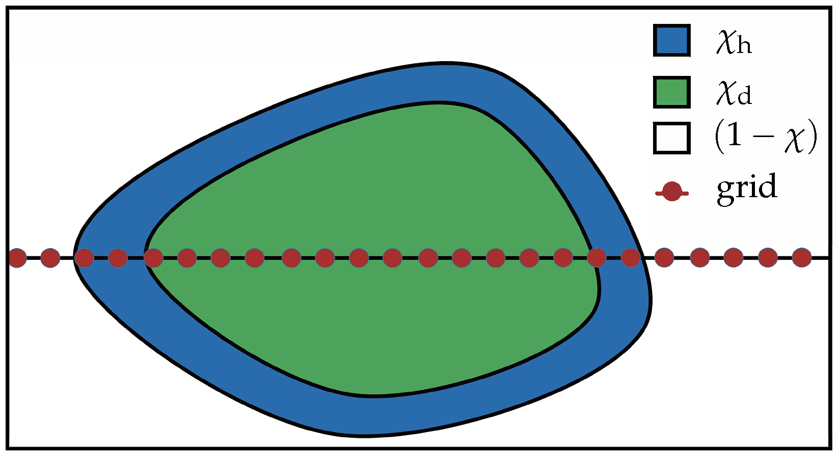
Figure 1. Illustration of different masking functions used for different penalization terms: χ h is the masking function for the hyperbolic thin layer, χ d is for the diffusive internal region, and ( 1 χ ) is for the external fluid region.
Fluids 06 00293 g001
Figure 2. Schematic diagram of the one-dimensional shock tube problem.
Fluids 06 00293 g002
Figure 3. Pressure profiles along the shock tube for (a) coarse ( N = 2 9 ) and (b) fine ( N = 2 11 ) grid resolutions. The penalized solution for the reflected shock is compared with that obtained using exact algebraic boundary conditions. The theoretical shock location is also indicated.
Fluids 06 00293 g003
Figure 4. L 2 -norm of the error for different values of η c .
Fluids 06 00293 g004
Figure 5. Supersonic flow reflecting from a wedge with the deflection angle θ = 10 , and the oblique shock angle of β 51 indicated by the yellow line: (a) density field, (b) adaptive grid colored by the pressure field.
Fluids 06 00293 g005
Figure 6. Numerical schlieren image (a) and the adaptive grid colored by the pressure field (b) for supersonic flow past an array of cylinders.
Fluids 06 00293 g006
Figure 7. Density and pressure field plots for fixed (upper half) and moving (bottom half) solid disks at (a) the beginning and (b) the end of simulations.
Fluids 06 00293 g007
Publisher’s Note: MDPI stays neutral with regard to jurisdictional claims in published maps and institutional affiliations.