1. Introduction
The flow over bluff bodies has been continuously studied for decades, due to its numerous applications, such as flow around aircraft, automobiles, bridges and high-rise buildings [
1]. Flow control can be passive, where the flow is modified by changing the shape of the body or the flow field, or active, where energy and/or mass are injected into the flow. Porous coatings are a passive flow control method that have received significant attention, primarily for their ability to reduce aerodynamic noise [
2]. However, they have also shown potential with regard to drag reduction. Porous coatings are not a new area of research, with a 1981 NASA report stating the importance of the study of turbulent boundary layer flow over porous surfaces for applications such as drag reduction, noise control and boundary layer control [
3]. As such, the use of porous treatments has been investigated for decades, with flow over river beds [
4], bluff bodies [
2], aerofoils [
5], porous screens [
6] and forest canopies [
7], among the areas being studied. When it comes to flow around bluff bodies, one of the main focuses is the control of vortex shedding, as this phenomenon can result in structural vibration, acoustic noise, increased drag, stresses on structures etc. [
2]. They have been identified as an effective means for the control of aerodynamic noise and vibration from bluff bodies, blunt edges and aerofoils with the general consensus being that they lead to the stabilisation of turbulence, vortex shedding attenuation, control of flow instabilities and reduction in noise [
8].
There is good agreement on the impact of a full porous coating on the wake of a cylinder, with the wake being stabilised due to the reduction or the delay of vortex shedding [
2,
9,
10,
11,
12,
13,
14,
15,
16,
17,
18,
19]. Consequently, many studies concluded that the porous coating reduced the fluctuation of aerodynamic forces [
2,
9,
10,
17,
18,
19]. With regard to drag reduction, there has been some discrepancy in the results with some studies finding an increase in drag [
2,
9,
14,
15,
16,
17,
20,
21] and others finding a decrease in drag [
11,
12,
17,
18,
19,
21].
Research on partial porous coatings is considerably more limited. Mimeau et al. [
22] investigated different configurations of porous coatings for flow control around a semicircular cylinder, with the goal of regularising flow around a side-view mirror. Using direct numerical simulation (DNS), they concluded that high-permeability porous layers on only the upper and lower edges of the body resulted in the best drag reduction.
Bathla and Kennedy [
23] investigated the use of 3D-printed porous coatings implemented partially along the span of a cylinder. They concluded that the full porous coatings reduced wake width and turbulence intensity and found that the partial coatings had the potential to provide the same or better turbulence reductions. Additionally, the partial coatings caused an increased wake width when compared to the fully coated case.
Hu et al., used 2D large eddy simulation (LES) to numerically investigate full and partial porous coatings at a Reynolds number of 3900 [
24]. Their findings agreed with those of Zhang et al. [
19], concluding that the porous coating is most effective when arranged around the separation point of the cylinder, achieving a 30% reduction in drag when compared to the smooth cylinder. Partial porous coatings were found to affect vortex shedding frequency, effectively reducing it, as the porous coating controls the transition to turbulence in the boundary layer, thus stabilising the shear layer, delaying the curling of the shear layer in the wake to generate vortices and suppressing the vortex shedding. They concluded that only coating the windward side of the cylinder resulted in an increase in drag, and the maximum drag reduction was for a cylinder with a full leeward coating.
Klausmann and Ruck [
25] experimentally examined the impact of a porous coating on the leeward side of a circular cylinder in cross-flow. They investigated various coating angles, layer thicknesses and porosities and concluded that the leeward porous layer results in a drag reduction in all cases. The coating reduced drag by 7.7–13.2% depending on the layer thickness and coating angle, with drag decreasing with increased thickness. The oscillation of the cylinder was reduced, and vortex shedding frequency was increased. In the near-wake region, there was a decrease in mean velocity components, velocity fluctuations, turbulent kinetic energy and normal stresses. The optimum drag reduction configuration, of those tested, was identified as a 100
coating angle and a 10 mm layer thickness, with the porosity and Reynolds number having little impact on the results. The porous coating weakened vortex shedding and the rolling up of the free shear layer, thus delaying vortex sheet formation and increasing cylinder base pressure. This increase started at
with the maximum at the base of the cylinder
, where
is the circumferential angle. These findings of Klausmann and Ruck are in line with those of Gabraith [
26], who concluded that a larger base bleed leads to longer vortex formation time and decreased drag.
This paper aims to help fill the research gap on cylinders with partial porous coatings by numerically replicating the experiment conducted by Klausmann and Ruck [
25]. As a few studies have indicated different, yet significant levels of drag reduction depending on the extent of the porous coating, this numerical study aims to verify and extend previous findings and provide more insight into the wall pressure distribution and the effect on the far-field wake.
2. Numerical Method
The numerical model was developed using ANSYS Fluent. An unsteady Reynolds-averaged Navier–Stokes (URANS) model was implemented using the two-equation SST
turbulence model. A URANS model was selected to capture the transient vortex shedding. The
SST model performs well for boundary layers with adverse pressure gradients, free shear flows and separated flows [
27]. Two-equation models use transport equations for two turbulence properties in addition to the Navier–Stokes equations. The
model uses the turbulence kinetic energy (k) and the specific dissipation rate (
). From these values and
, an empirical constant, the kinematic eddy viscosity
is modelled as follows:
SIMPLE pressure–velocity coupling, second-order discretisation and second-order implicit time discretisation were used. The time step selected was
s, which resulted in a Courant number (CFL) < 1 for the majority of the flow field, with a maximum CFL of 7.9 for the smooth cylinder case. This maximum Courant number decreased further for the porous coated cases. While the Courant number represents more of a limitation for density-based solvers, for a pressure-based solver, as was used here, it provides an indication of the level of numerical damping. The maximum number of iterations per time step was set at 50. Numerical models similar to this have proven to be accurate for flow over porous coated cylinders in the past, with Liu et al. [
18,
20] utilising a URANS model with a two-equation SST
turbulence model and achieving good agreement with the experimental literature.
The flow domain and cylinder geometry were chosen to closely replicate the test section of an existing water tunnel test facility in our research laboratory (cylinder outer diameter
mm, with water at 20
C as the working fluid). The turbulence intensity at the inlet was 1% with a turbulent length scale of
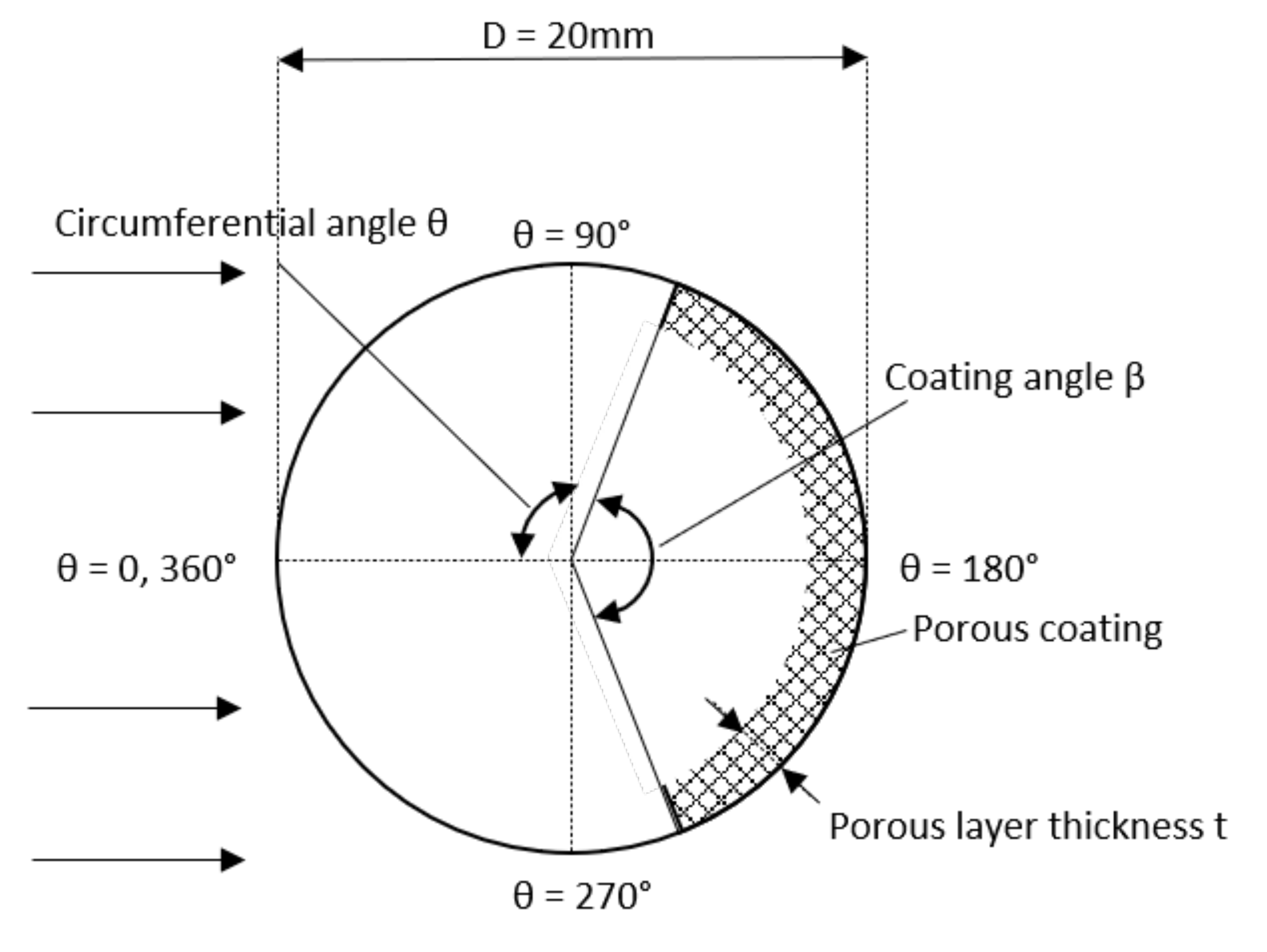
m. The details of the porous coating are shown in
Figure 1. For clarity, it is important to define the angles that were used throughout the results. The circumferential angle
was
on the windward side of the cylinder and increased clockwise. The porous coating angle
was the full angle covered by the porous coating and was always symmetrical about
. Five angles of partial porous coating were investigated to allow for a comparison with Klausmann and Ruck’s experimental results [
25]:
and
. Additionally, a fully porous coated cylinder was investigated to provide another baseline for comparison. These were investigated at a Reynolds number of
, corresponding to an x-velocity at the inlet of 2.11 ms
and a thickness-to-diameter ratio of 14.3%. The linear porosity of the coating remained constant at 20 pores per inch (PPI), as Klausmann and Ruck found it to have limited impact [
25].
The microscopic momentum equation for an incompressible flow in a porous medium is given by the Navier–Stokes equation:
From Equation (
2), Hsu and Cheng [
28] derived the following macroscopic momentum equation for incompressible flow in a variable porosity medium:
where
is the Darcy velocity. This is known as the Brinkman–Forchheimer extended Darcy model, and it describes momentum conservation in a porous medium. The conservation of mass in a porous medium is described by the following equation:
ANSYS Fluent models porous media through the addition of a momentum source term to the Navier–Stokes equations. This source term can be broken down into two components: the viscous loss term (the Darcy term) and an inertial loss term. The momentum sink contributes to the pressure gradient in the porous cell, creating a pressure drop proportional to the fluid velocity in the cell [
29].
where
is the source term for the
x,
y or
z momentum equation and
D and
C are diagonal matrices with
and
on the diagonals, respectively. For a simple homogeneous porous media, Equation (
5) simplifies to:
For low Reynolds number flows, the nonlinear term related to form drag is negligible, and thus, the equation reduces to Darcy’s law as defined in Equation (
7).
This linear relationship is captured in Fluent via the viscous coefficient, defined as the reciprocal of permeability . At higher flow velocities, accounts for inertial losses in the porous medium and was input as the inertial resistance coefficient during model setup. The directions over which these act are defined in Fluent using the direction vectors, which are orthogonal for a 2D isotropic porous media.
One way of determining the viscous and inertial resistance coefficients is to use the values of
K and
, which were calculated from the following semi-empirical correlation suggested by Ergun [
30] for flow through an isotropic packed bed over a wide range of Reynolds numbers. The experimentally derived coefficients were 150 and 1.75 to parameterise the microscopic geometry of the porous media derived by Ergun, presented by Vafai [
31] and used by Liu et al. [
18,
20]:
where
is the volumetric porosity and
is the particle diameter in the packed bed. Combining Equations (
8) and (
9) allows for the calculation of
and
K as follows:
Alternatively, the viscous and inertial resistance coefficients can be derived from experimental pressure loss data. This is the approach taken in the present study. Klausmann and Ruck [
25] defined the pressure loss coefficient
(m
as:
where
and
are the pressure at the windward and leeward side of a block of porous foam filling a test section and
t is the thickness of the porous layer. They specified this coefficient for each of the three porosities of foams used in their experiment with
500 m
. From this, it is possible to plot the range of pressure drops through a porous foam against the flow velocity. This was used as a set of data for validating the porous media inputs in ANSYS Fluent. There was good agreement between the sets of results, with an RMS deviation of 0.01% for the 20 PPI coating.
Equation (
12) defines the pressure loss through the porous coating as dependent on the second-order term only, implying that the linear Darcy term (i.e., the viscous resistance) has a negligible contribution to the pressure loss. Thus, the pressure loss coefficient
corresponds to the inertial resistance for flow through the porous coating.
A structured quadrilateral mesh was designed to allow for control over the areas of refinement. In particular, the mesh was refined near the wall of the cylinder and in the downstream wake region to capture vortex shedding. A primary focus of the mesh development was to ensure that
at the cylinder wall accurately resolved the boundary layer. Four meshes of different densities were generated that all met this
requirement, and the impact of mesh density on the characteristic dimensionless numbers was investigated, as shown in
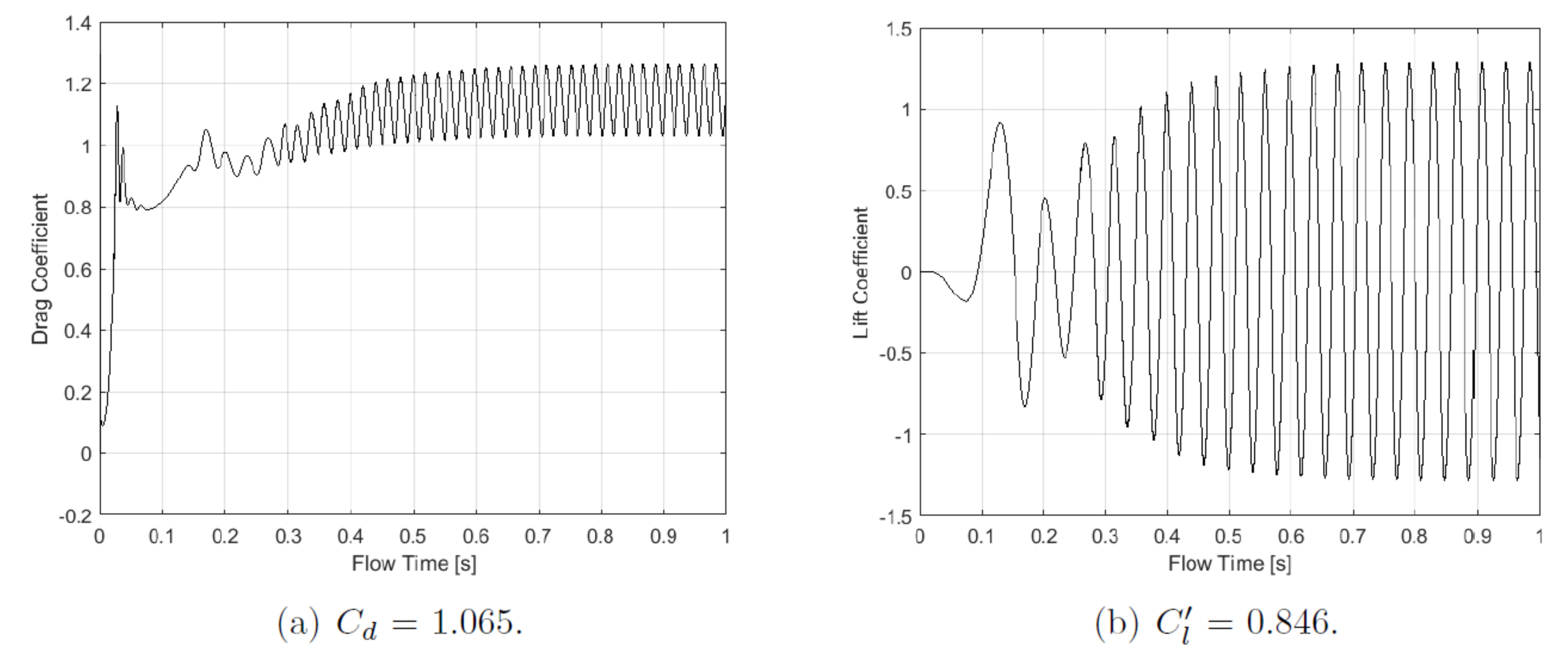
Table 1. All data were averaged over a period of 1–2 s of flow time in the quasi-steady state or statistically steady-state conditions, which are typically achieved after a transition period of approximately 1 s, as shown in
Figure 2 for the drag and lift coefficient for a smooth cylinder at
.
There is significant experimental and numerical data available for use in model validation. Roshko’s 1961 investigation into high Reynolds number flow [
32] provides a summary of much of these data. From this report, expected values for the Strouhal number (taken from Etkin and Ribner’s [
33] 1958 report on aerodynamic noise) and the drag coefficient (from Wieselsberger’s [
34] 1922 technical notes) can be obtained for the relevant Reynolds number range. Similarly, Norberg [
35] and Jiang [
36] provided summaries of the values for the RMS lift coefficient and separation angle, respectively, over a wide range of Reynolds numbers. The results were also compared against the drag coefficient values reported by Klausmann and Ruck [
25] for a smooth cylinder. Additionally, results from previous numerical simulations were used to confirm that errors compared to experimental results were within the range experienced by others. Liu et al. [
18] and Orselli et al., conducted both 2D URANS and 3D LES simulations at a Reynolds number of
–
. Although this exceeds the
used in the present study, the results are still included in
Table 1 for reference.
All mesh densities overestimated the RMS lift coefficient and Strouhal number, which is in line with the findings of other 2D simulations [
18,
37]. With the exception of the finest mesh, it can be said that as mesh density increases, the overshoot of the RMS lift coefficient also increases, while the Strouhal number remains constant. The vortex shedding Strouhal number is accurate only to two decimal places as a result of the frequency domain resolution, which is the reciprocal of the simulated flow time (1 s), i.e., 1 Hz. The main priority of the mesh selection was the time-averaged drag coefficient, as this has been accurately modelled in 2D simulations by Liu et al. [
18] and is a key parameter of interest in this project. As mesh density increases, there is a convergence towards experimental values for the time-averaged drag coefficient. However, there is a clear underestimation of the drag, which is similarly evident in the numerical results of Orselli et al. [
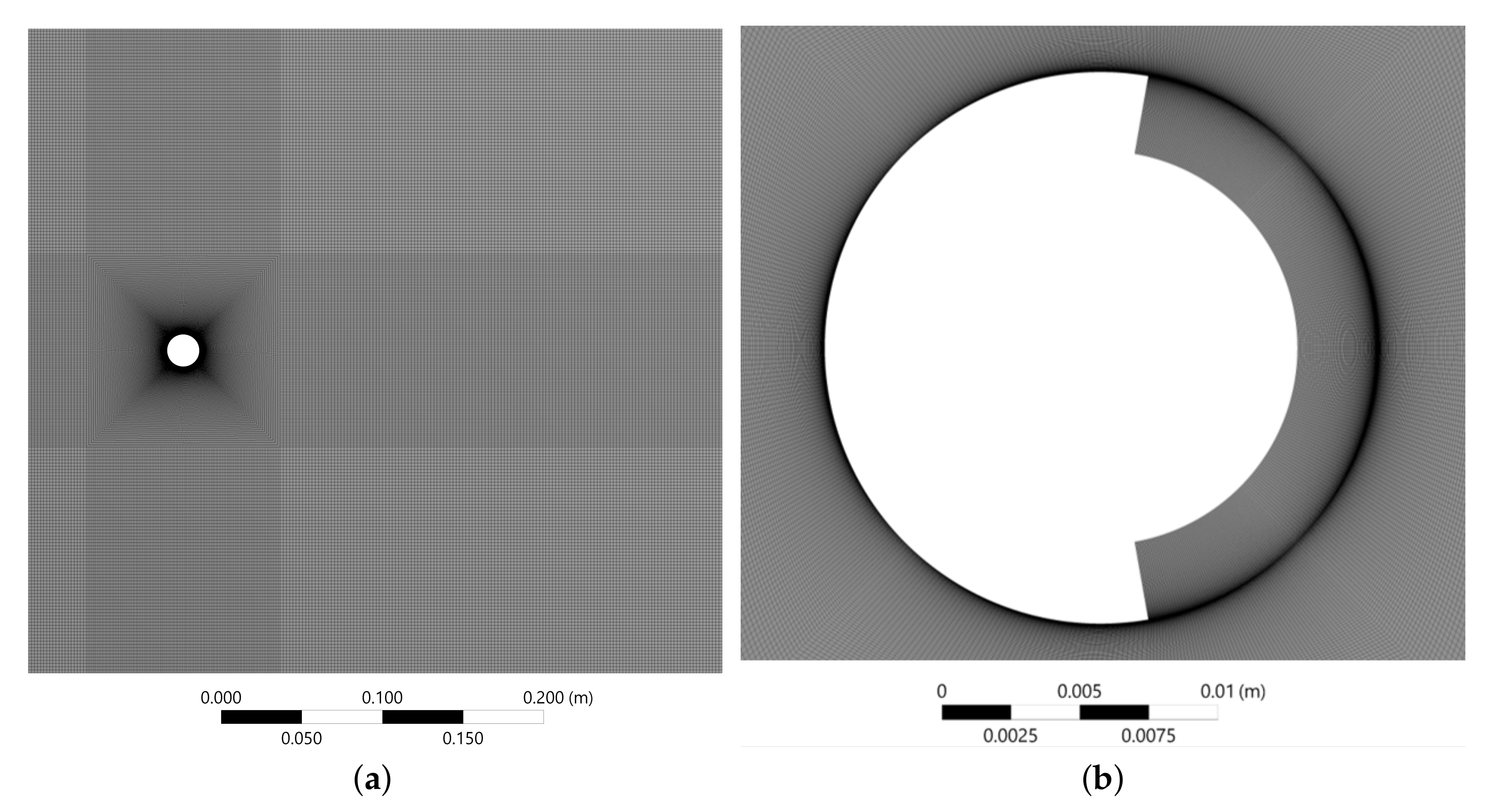
37]. The mesh with 155,000 elements was deemed a reasonable balance between accuracy and simulation run time. This final mesh can be seen in
Figure 3a. The cases with a porous coating had an additional meshing requirement for this region. This can be seen in
Figure 3b for a coating angle of 160
and a thickness-to-diameter ratio of 14.3%. There is a bias towards the interface between the porous medium and the flow.
The grid convergence index (GCI) method was used to estimate the discretisation error, as outlined in [
38]. Three successively finer meshes with a constant refinement ratio
were investigated for spatial convergence using the equations below. Here, the fine (155,000 elements), medium (109,000 elements) and coarse (77,000 elements) grids were used, and
f denotes the parameter of interest
. This resulted in an approximate relative error
and a fine-grid convergence index
. The apparent order p is defined according to Equation (
13), where
in this case as r is constant,
and
.
3. Results
Five different angles of partial porous coatings and a fully porous coated cylinder were investigated for
, with layer thickness
= 14.3% and a porosity of 20 PPI.
Figure 4a compares the pressure distribution for the smooth cylinder and the
coating. Although not shown, the trends seen here are also present for
,
and
. The pressure distribution is almost congruent with the smooth cylinder around the windward side until an angle of approximately
. Past this point, there is an increase in pressure for the porous coated cases, with the shape of the distribution still matching the smooth cylinder closely.
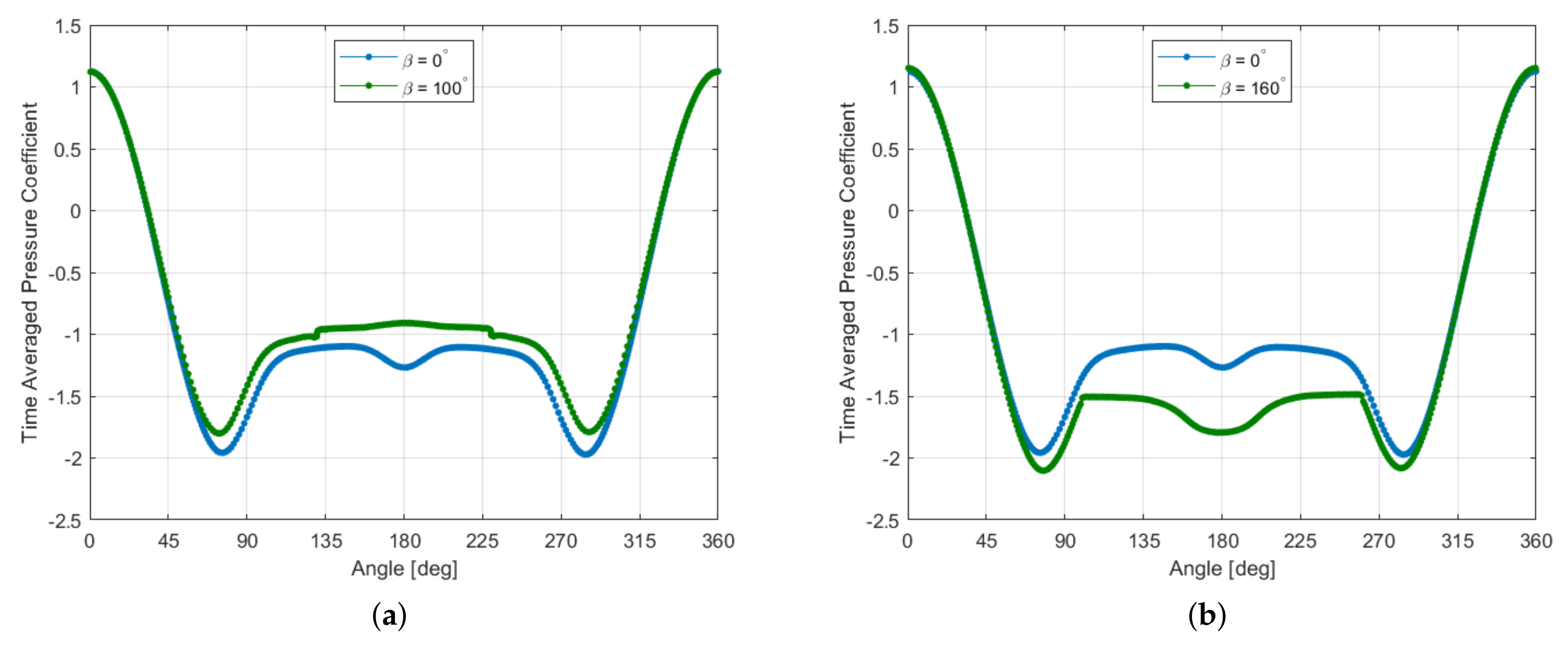
At the point where the porous coating begins and ends, , there is a sudden increase and decrease in pressure, respectively. Around the porous coating, the pressure remains relatively constant. This is in contrast to the dip in pressure noticeable at the rear of the smooth cylinder. As the area covered by the porous coating increases, so does the region of constant pressure around the leeward side.
There are considerable differences in the
case, as shown in
Figure 4b. Once again, the pressure is mostly congruent until an angle of approximately
. After this point, the pressure on the porous coated case continues to decrease, exceeding the minimum pressure of the smooth cylinder. The start of the coating occurs while the pressure is still increasing, at
, and the pressure levels off at this point. As such, there is a considerable decrease in pressure on the leeward side of the cylinder in comparison to all other cases. Noticeably, while the pressure stops decreasing around the porous coating, there is a dip at the rear of the cylinder similar to that of the smooth case. This is in contrast to the relatively constant pressures around all other porous coating angles. The full porous coating sees a considerable increase in pressure on both the windward and leeward side of the cylinder.
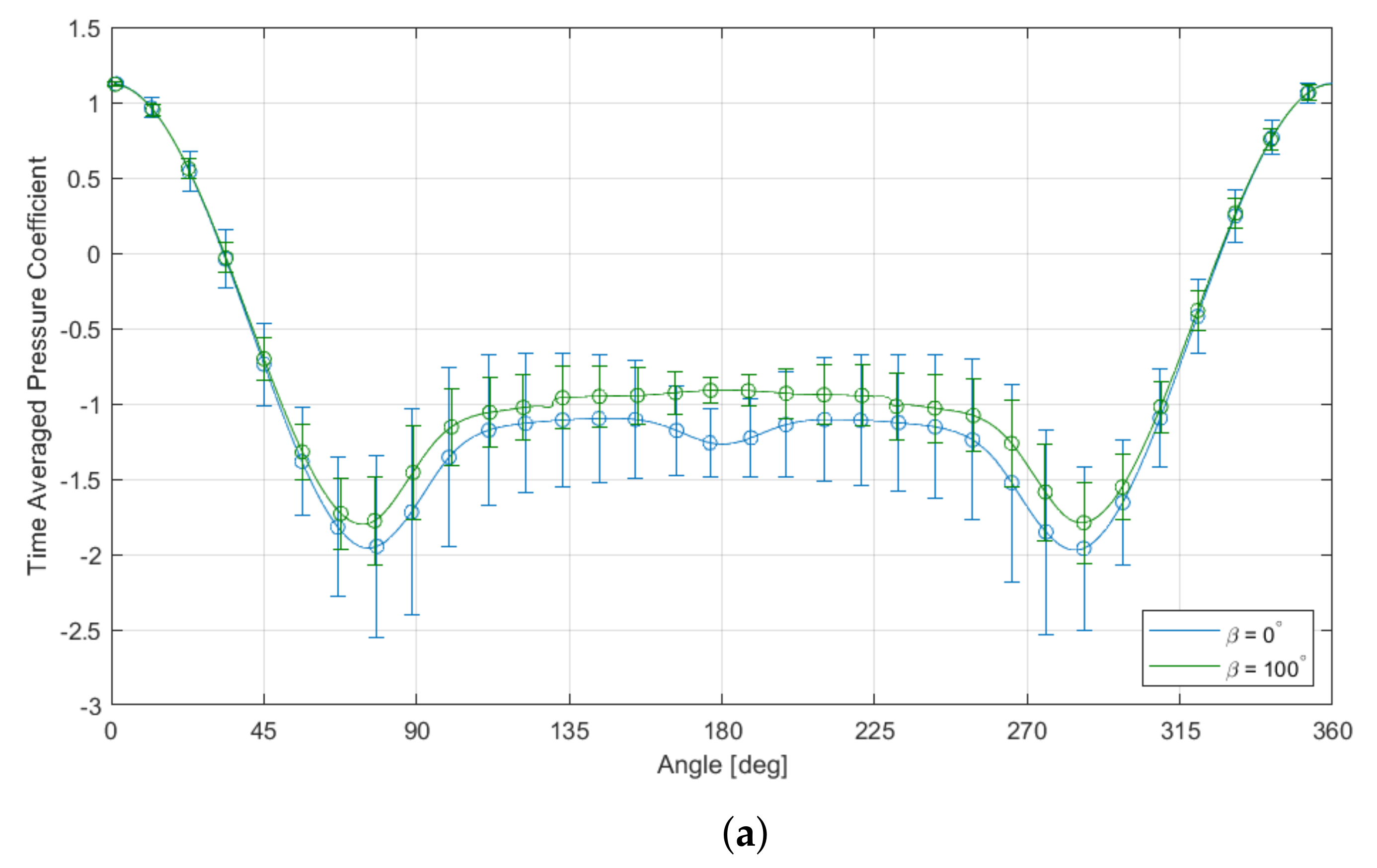
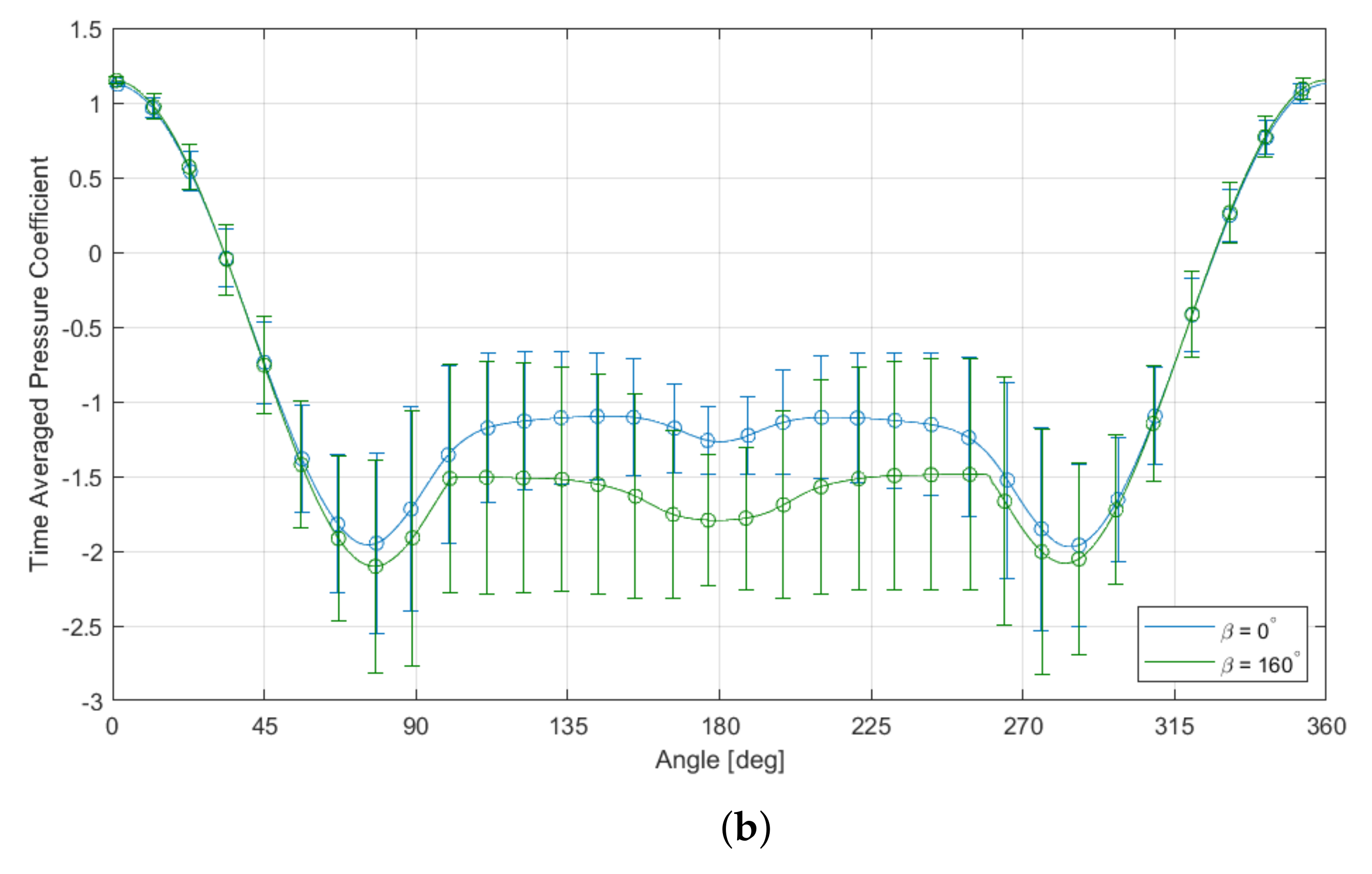
Figure 5a shows the pressure distribution of the
coating against the smooth cylinder, with bars depicting the standard deviation of the pressure at that point. The standard deviation was calculated over a flow time period of 1 s, equivalent to approximately 25–26 vortex shedding cycles. There is a clear decrease in the pressure fluctuations on both the windward and leeward sides of the cylinder. The opposite is true for
, as seen in
Figure 5b, where there is an increase in the pressure fluctuations, particularly in and close to the porous region. Although not shown here, the full porous coating saw a significant decrease in pressure fluctuations around the entire cylinder.
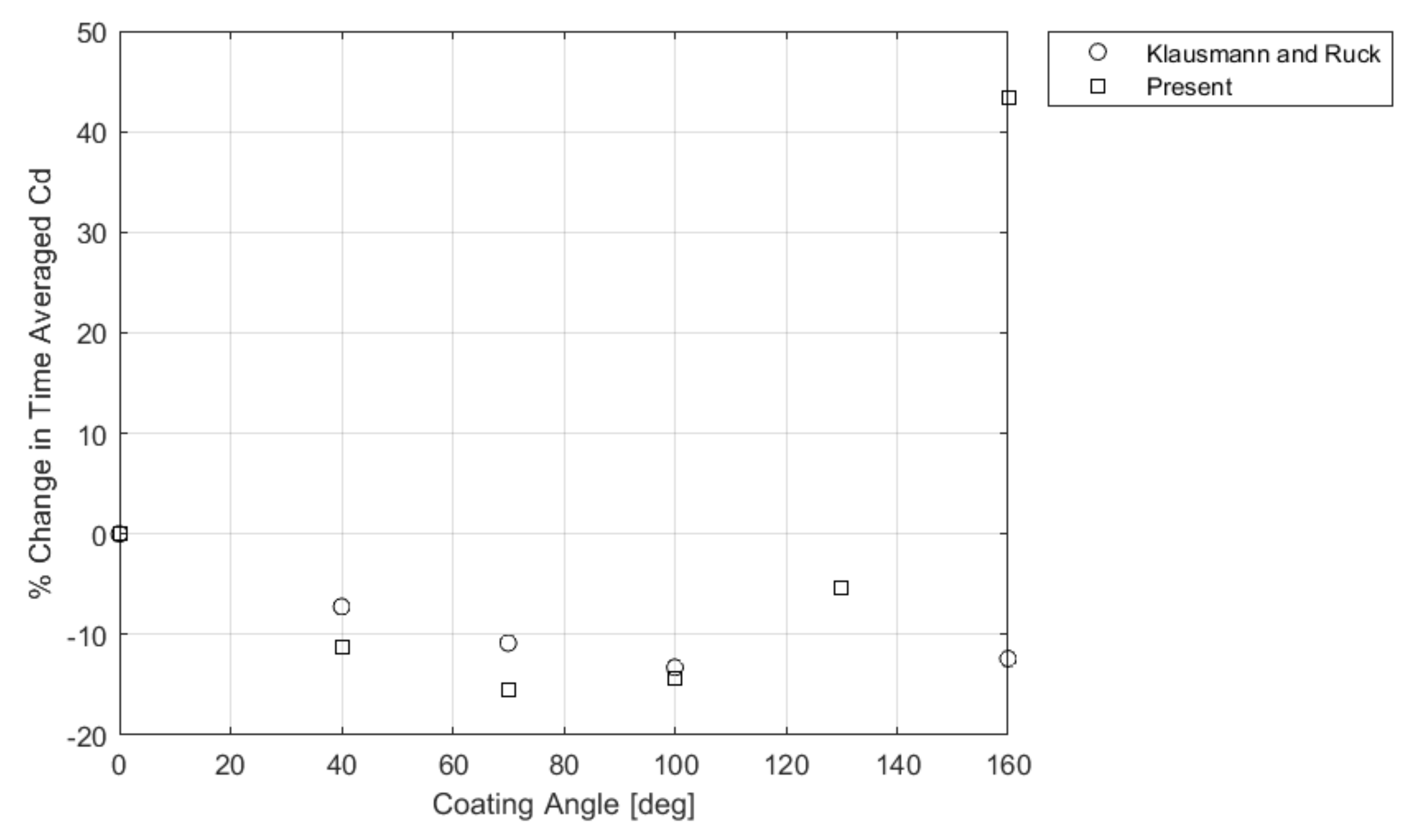
Figure 6 shows the percentage change in the time-averaged drag coefficient, which resulted from the variable pressure distribution on the cylinders with different partial coating angles. This was compared against the experimental data adapted from Klausmann and Ruck [
25]. Coating angles from
= 40
–130
resulted in a reduction in drag, with the maximum drag reduction at
. A
coating increased the drag above that of a fully coated cylinder. Conversely, Klausmann and Ruck found a decrease in drag at this coating angle. For all cases with reduced drag, there was a greater percentage decrease for the present study than found experimentally, with
being closest to the experimental values.
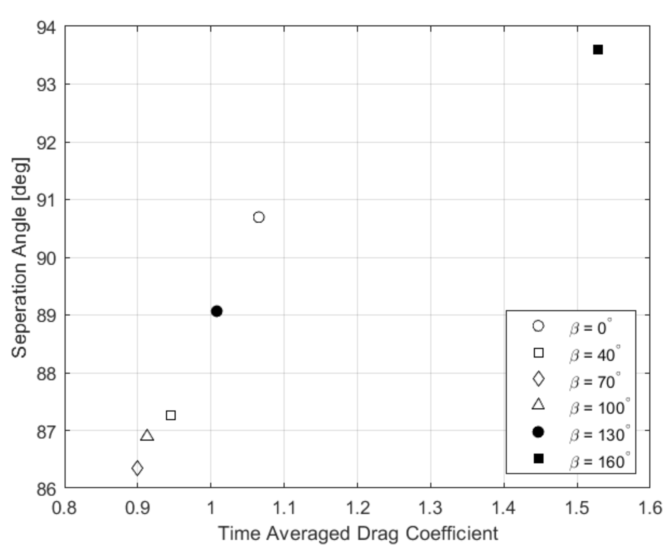
Table 2 shows the results for all angles investigated against the smooth case. The full porous coating showed considerable dampening of the lift forces, with a decrease in vortex shedding frequency and the RMS lift coefficient. There was a 42% increase in the drag coefficient for the full coating. For the partial coatings, there was also significant dampening of the lift forces in all cases with a decrease in drag. These cases also saw a decrease in the separation angle. In addition to an increase in drag, the
coating saw a large increase in lift force fluctuations and a smaller increase in the separation angle. There was an increase in shedding frequency for
, and it remained unchanged for the smaller coating angles to the resolution of this study. Notably, vortex shedding was considerably delayed for all coating angles when compared to a smooth cylinder. Time to quasi-steady state increased with porous coating angle. The relationship between drag and separation angle is further investigated in
Figure 7, where a linear relationship between increase separation angle and increased drag can be seen. Here,
was determined using time-averaged wall shear stress data at each mesh node. These data were interpolated between the two nodes on either side of the zero-crossing to determine the most accurate value for
possible with the current computational grid.
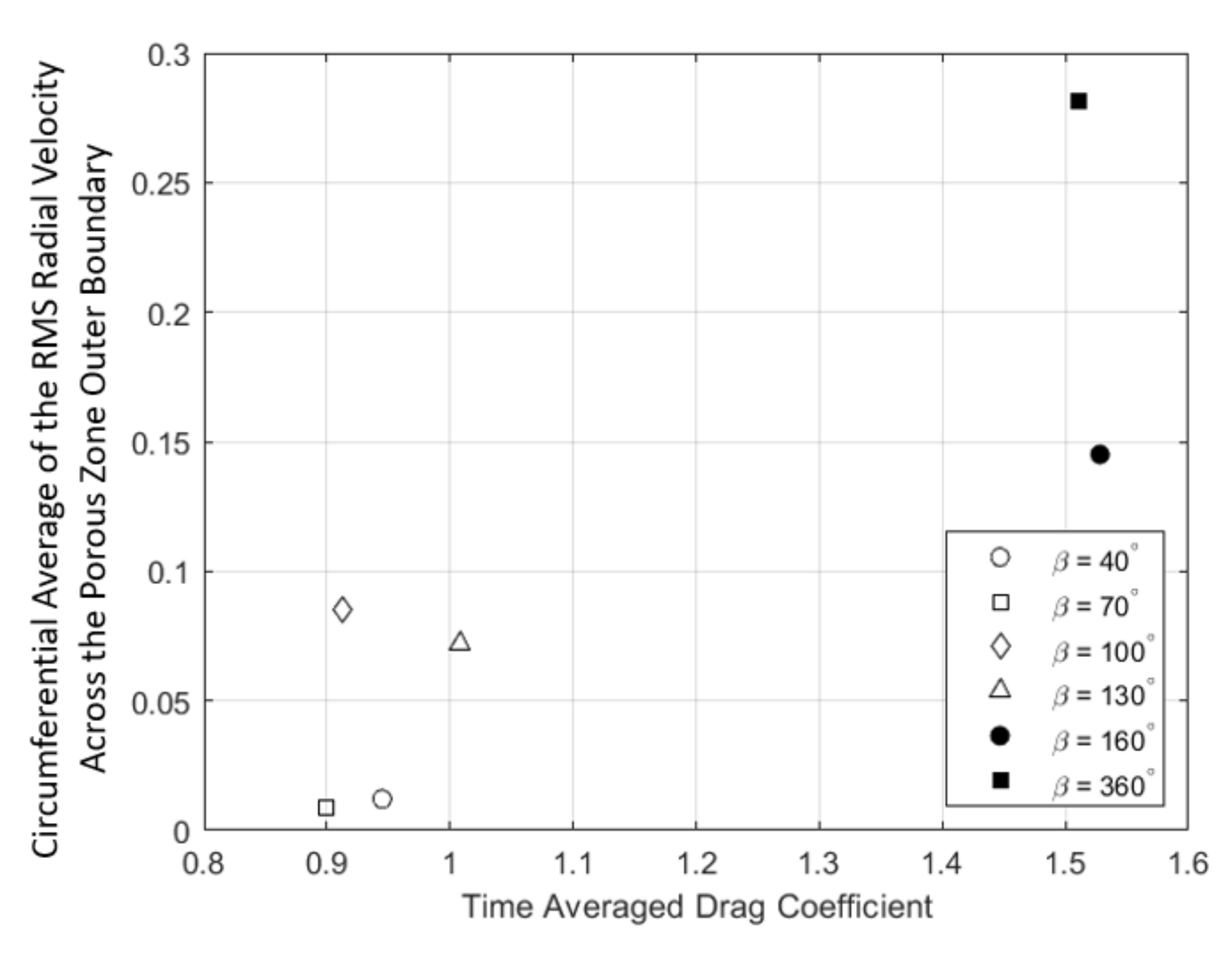
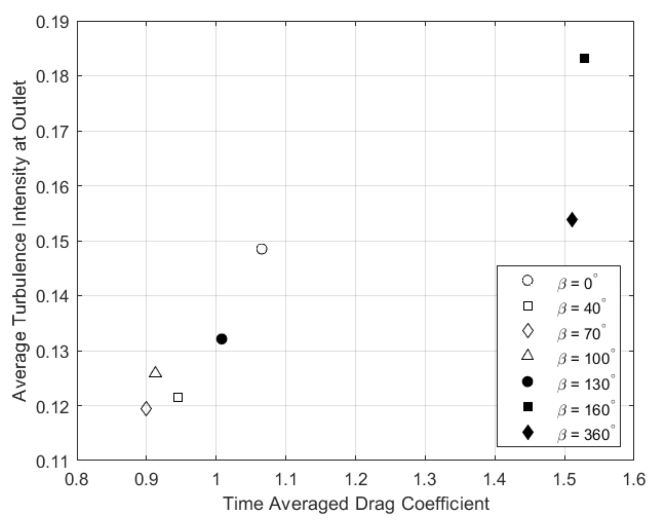
The introduction of a porous coating resulted in a new parameter of interest: the radial velocity across the porous coating boundary. The circumferential average of the RMS radial velocity across the porous zone outer boundary was taken, to illustrate the variation in the level of flow passing in and out of the porous medium. This is shown plotted against the time-averaged drag coefficient in
Figure 8. While the relationship is far from linear, there is a clear positive correlation between the drag coefficient and increased flow across the boundary. Interestingly, there is not a linear relationship between the increased porous coating angle and radial velocity, with more flow for the 40
case than the 70
case, and similarly more flow for the 100
case than for 130
.
Figure 9 shows the time-averaged turbulence intensity across the outlet against the drag coefficient. There is an apparent linear relationship between the two, with increased turbulence intensity as drag increases. Excluding
, there is a decrease in turbulence intensity for all partially coated cylinders when compared to the smooth cylinder. The maximum reduction is 18% at
. The
and
cases saw 24% and 11% increases, respectively. The differing wakes for each case resulted in varying wake widths, as shown in
Table 3.
The wake is defined as the region where the time-averaged flow velocity across the outlet is below 95% of the maximum. The wake width w was determined at an arbitrary downstream location of = 16.2. For coating angles with a reduction in drag, between 40 and 130, there was a decrease in wake width. The wake width remained unchanged for the 40, 70 and 130 cases. For the cases with increased drag, there was a considerable increase in wake width, with a 16% and 28% increase for the 160 and full porous coating, respectively. Even for cases with constant wake widths, there was a variation in the velocity profile across the outlet. The wake velocity varied with drag, with an decrease for cases with decreased drag, and vice versa.
4. Discussion
The fully porous coated cylinder acts as another comparison for the partially porous coated cases as there have been numerous experimental and numerical studies of porous coated cylinders such as this. The first point of note is the considerable increase in simulation time required, as the time to quasi-steady-state vortex shedding increased by approximately 350% when compared to the smooth case. This is in agreement with both the experimental and numerical literature, all of which found there was a significant delay in shear layer roll up and, thus, vortex shedding [
2,
9,
10,
11,
12,
13,
14,
15,
16,
17,
18,
19,
23,
24,
25]. Naito et al. [
14,
15] attribute this to the stabilisation of the shear layer as a result of low-energy fluid being injected downstream of the porous layer. Similarly, Yuan et al. [
16] and Zhang et al. [
19] concluded it was a result of increased surface pressure regulating and stabilising boundary layer flow and thus decreasing flow velocity outside the boundary layer. This was evident in this case as the region of low velocity fluid in the lee of the cylinder increased considerably as kinetic energy was dissipated by the porous coating, shown in
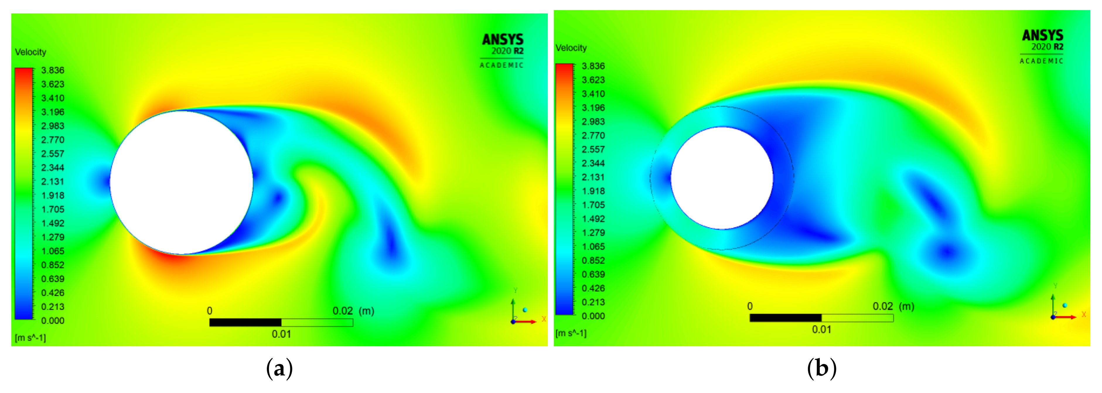
Figure 10. The decrease in velocity was accompanied by a corresponding increase in pressure on the leeward side of the cylinder.
The stabilisation of the flow was seen in the decreased pressure fluctuations on the cylinder. The change in pressure distribution on the porous coated cylinder had a significant impact on the aerodynamic forces. Lift and drag fluctuations were dampened by the porous coating, with a 62% decrease in the RMS lift coefficient. The increase in leeward pressure was accompanied by a greater increase in windward pressure, resulting in a 42% increase in the drag coefficient. In addition to the delay of vortex shedding and suppression of the aerodynamic forces, it is likely that the stabilisation of the shear layer can be attributed to the 54% increase in the separation angle and the 4% decrease in the Strouhal number.
The simulation time for all partial porous coatings was increased compared to the smooth cylinder. Klausmann and Ruck attributed this delay in the establishment of a quasi-steady-state vortex sheet to the increase in base pressure, leading to a decrease in pressure fluctuations and weakened vortex shedding [
25]. By examining the pressure distributions in this study, it is evident that similar conclusions can be drawn.
For coating angles
= 40
–130
, the porous coatings had a similar impact on the pressure distribution of the cylinder. As with the full porous coating, the flow was retarded, resulting in low-energy fluid ejected into the free-stream and a corresponding increase in pressure in the lee. This can be seen for
in
Figure 11a. On the windward side, the pressure distribution was congruent with the smooth case only until
. This closely matches the findings of Klausmann and Ruck, who found congruency until
[
25]. Past this point, there was an increase in pressure for the porous coated cases, with the shape of the distribution still matching the smooth cylinder closely. This illustrates that the leeward porous coating also influences the pressure distribution upstream of itself, something also found by Klausmann and Ruck. The significant reduction of pressure fluctuations showed that the porous coating resulted in a regularisation of the flow, once again agreeing with the results of Klausmann and Ruck [
25].
Additionally, the variation in pressure on the cylinders resulted in significant dampening of the aerodynamic forces. The increase in pressure on the windward side was small in comparison to the fully coated cylinder, as it was the result of upstream effects, as opposed to flow directly through the coating. Thus, the increase in pressure on the leeward side resulted in a decrease in drag. In contrast to the fully coated cylinder, separation of the flow occurred earlier than for the smooth cylinder. The clear linear relationship between drag and separation angle strongly disagrees with Klausmann and Ruck, who found that separation was unaffected by the leeward coating [
25]. Notably, their definition of the separation angle, the point of maximum RMS
, differs from the one used here. However, both definitions resulted in varying separation angle in this study. This is most likely a result of Klausmann and Ruck’s resolution, which was limited to the pressure tappings’ every 5
around the cylinder. With the exception of the fully porous case, the variance in the separation angle from the smooth case was less than
for all coatings. With the fully porous case, the delay in separation angle was likely attributed to the stabilisation of the shear layer. As separation occurs on the windward side for all partially coated cylinders, the decrease in the separation angle could be a result of the upwind effect not having the same stabilising effect as the full porous coating.
The effects of the porous coating carried on downstream, as there was a decrease in wake width and a decrease in average turbulence intensity and velocity at the outlet. Klausmann and Ruck found an increase in vortex shedding frequency and thus a reduction in wake width, citing the results of Roshko [
39,
40], who found that the Strouhal number increases with decreased wake width. This study found this to be the case for coating angles of
and
. The
and
coatings saw no change in the Strouhal number, and thus, an increase in resolution is required to see if these results are in agreement with Klausmann and Ruck and Roshko. Additionally, Klausmann and Ruck found a decrease in turbulent kinetic energy in the free shear layer with increased coating angle, with a 20% decrease for
[
25]. This study found a 15% decrease in turbulence intensity at the outlet for
.
The optimum angle for drag reduction of those investigated was 70
, which resulted in a 16% decrease. Klausmann and Ruck found 100
to be the best angle for drag reduction, with a 13% reduction in drag [
25] over a range of Reynolds numbers. Here, we see a 14% decrease for the same configuration. Perhaps the reason why 70
is that the optimum angle can be found by looking at the radial velocity across the porous boundary, the distribution of which varies with coating angle. For
= 40
–130
, the peaks lie at the edges of the coating, indicating that inflow and outflow occur most at these locations. The 70
coating had the minimum amount of flow across the boundary of all cases investigated, which is potentially linked to its optimal drag reduction. However, there was not a clear correlation between radial velocity and drag.
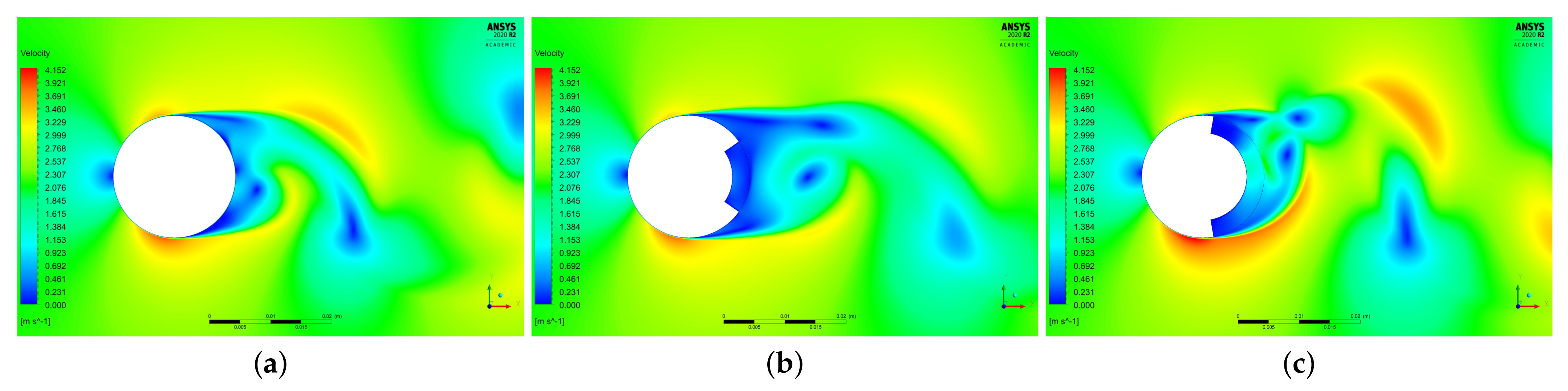
The results for the 160
coating differed greatly from all discussed above. The contours of velocity in
Figure 11c. show there was actually an increase in velocity around the cylinder, and the low velocity region in the lee was smaller than all other cases. Thus, there was a decrease in leeward pressure and a corresponding increase in drag. The pressure fluctuations on the cylinder increased, causing an increase in the RMS lift coefficient. As with the fully porous case, the separation angle, wake width and average turbulence intensity across the outlet increased. The increase in the wake width was accompanied by an increase in the Strouhal number, disagreeing with the findings of Roshko [
39,
40]. Conversely, Klausmann and Ruck found a decrease in drag at this coating angle [
25]. With such contradictory results, it is important to acknowledge the possibility of the 2D assumption limiting the accuracy of a complex case.
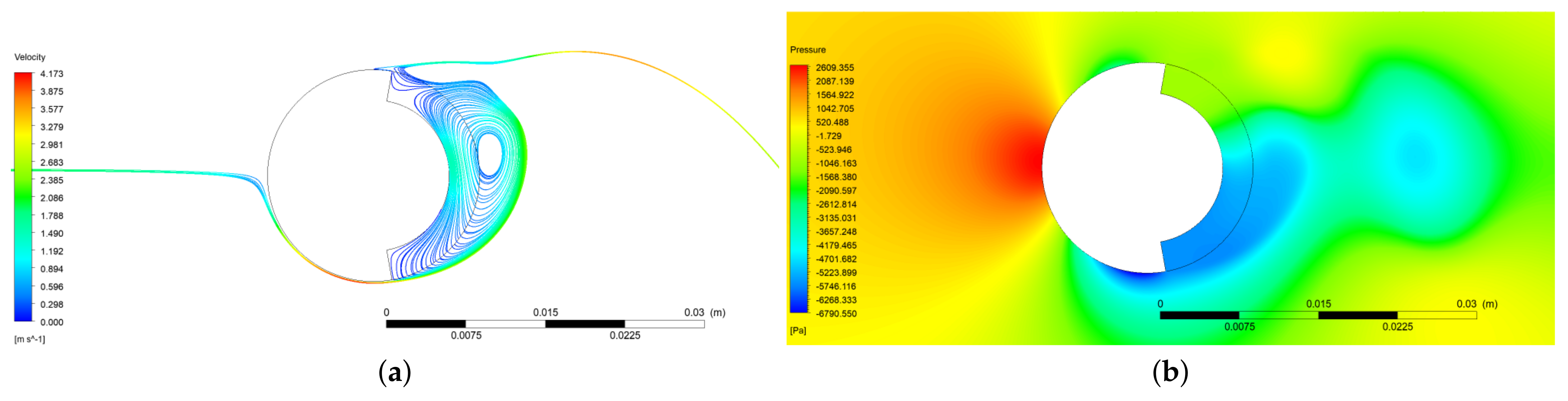
The key difference notable with the 160
case is the increased coverage of the lee of the cylinder, with the the separation angle and the start of the coating being only 6
apart. Perhaps it is the interference between the separating flow and the coating that was causing some of the discrepancies. Streamlines at various flow times showed recirculation adjacent to the region of separating flow. This was a result of pressure gradients forming across the coating, as seen in
Figure 12. However, this can also be seen to some extent for the 130
case and, thus, cannot be fully attributed to the considerably different flow field. The 160
coating also saw an increase in the level of inflow and outflow across the porous boundary, with the peak areas of radial flow moving inwards towards the centre of the coating. This may be indicative of the increased levels of flow recirculation for this coating angle.
5. Conclusions
The primary goal of this research was the development of a numerical model to investigate various configurations of a leeward porous coating on a cylinder in cross-flow. The model was developed with the aim of verifying and extending previous findings on partially porous coated cylinders by replicating the experiment conducted by Klausmann and Ruck [
25]. Particular focus was placed on investigating the wall pressure distribution and the effect on the far-field wake. The porous coating was integrated into the cylinder on the leeward side and was investigated at varying coating angles at a constant Reynolds number
=
, thickness-to-diameter ratio of 14.3% and a porosity of 20 PPI.
A comparison of the results for a smooth cylinder and both experimental and numerical results from the literature was used to validate the model setup and the computational grid. The grid convergence index method was used to estimate the discretisation error for this mesh, which then formed the basis for all subsequent meshes on the porous coated cylinders. The smooth case produced results within the range of previous numerical simulations, and the differences from the experimental literature were likely attributable to the 2D assumption.
A cylinder with a full porous coating was simulated, which provided another baseline for comparing partial porous coatings. The impact of the porous coating closely matched that of the literature, with a significant delay in vortex shedding likely a result of the expanded low-velocity region in the lee of the cylinder caused by dissipation in the porous layer. There was an increase in leeward pressure and an even greater increase in windward pressure, which resulted in a 42% increase in drag. This corresponds to the drag force on a solid cylinder with a 42% increase in diameter. The stabilisation of the flow was evident in the decrease in pressure and aerodynamic force fluctuations. The widened wake resulted in a 4% decrease in vortex shedding frequency.
Leeward partial porous coatings were investigated with angles between and . They were found to alter the pressure on the cylinder upwind of themselves, starting at a circumferential angle . This agreed closely with the results of Klausmann and Ruck; however neither their study nor this study can provide a clear reasoning behind this upwind effect. With the exception of a coating angle, from this point onward, all cases resulted in an increase in pressure. This is likely attributable to the dissipation of kinetic energy by the porous coating and resulted in drag reductions between 5% and 16%. This would correspond to a solid cylinder with a decrease in diameter of 5–16%. There was a significant reduction in the fluctuations of the pressure and aerodynamic forces and a delay in vortex shedding.
The optimum angle for drag reduction was found to be . The wake width as it was defined here depends only on the coating angle. There was a decrease in wake width with decreased drag and a corresponding increase in the Strouhal number for some cases, with an increased resolution required to fully examine this trend. Additionally, with decreased drag, there was a decrease in turbulence intensity at the outlet. There was a linear relationship between drag and separation angle, particularly for the cases with reduced drag. This is in contrast with Klausmann and Ruck, who found the separation angle to be unaffected by the leeward porous coating. However, care should be taken in directly comparing these findings, since our definition of the separation angle allows for higher spatial resolution than the one used by Klausmann and Ruck, which was based on pressure tappings spaced at 5 intervals.
The 160 coating was found to behave differently from all other cases, with results more similar to the fully porous coated cylinder. This is possibly attributable to the closeness of the separation point and the start of the coating, flow recirculation and the inaccuracies of 2D modelling; however, more investigation is needed into the flow field for this angle.
In most cases, configurations with reduced drag saw decreased flow crossing the porous boundary. Additional research into the impact of radial velocity on drag is required to gain a more comprehensive understanding of this phenomenon.


