Abstract
In this study, numerical computation is used to investigate the hydrodynamic characteristics of a torpedo-shaped underwater glider. The physical model of a torpedo-shaped underwater glider is developed by Myring profile equations and analyzed by the computational fluid dynamics approach. The Navier–Stokes equations and the energy equation coupled with the appropriate boundary conditions are solved numerically by using Comsol Multiphysics software. The numerical results contribute to the major part of reducing the effects of fluid flow on the glider’s profile and make the underwater glider more hydrodynamically efficient. The drag and lift forces acting on the underwater glider are enhanced by a higher velocity and a larger angle of attack of the underwater glider. Since the obtained results show a good observation with the experimental works, the need and the practicality of using CFD in the glider design process are proven.
1. Introduction
In recent years, the underwater glider has received widespread attention because of its potential applications, such as oceanographic, military purposes, and mineral exploration programs for economic development. [1,2,3,4]. This is a new type of autonomous underwater vehicle (AUV) that uses adjustments in buoyancy and mass center position [5,6]. It is typically equipped with many different types of sensors to collect data in remote locations that are too difficult and risky for humans. In early 1957, the conceptual design of AUVs was first developed at the University of Washington by Murphy et al. Another early AUV was proposed by Myring that gives the shape of nose and tail with a minimal drag coefficient [7]. According to Myring’s works, there are several factors of the glider’s profile that can change the drag coefficient (). The results indicated that a change in the tail and nose profile might not obtain much difference in . However, the other parts of the glider tend to make significant changes in the drag coefficient at the same thickness ratio. In addition, the new type of underwater vehicle is designed in a torpedo shape with fixed wings, which can travel long distances over long periods by using a pump to change its buoyancy [8,9,10]. To go down or come up continuously to the water’s surface, the wings of the underwater glider generate the lift force, which is created by the buoyancy. Since the underwater glider pumps in and pumps out water alternately, its trajectory is formed in a sawtooth operating pattern and has a slow speed [11]. The glider angle of attack and buoyancy are two of the main factors that affect the glider velocity. The more change in the buoyancy, the higher the gliding velocity at a certain angle of attack.
Computational fluid dynamics (CFD) is known as a very useful tool to solve numerical problems that relate to fluid mechanics. The scheme for CFD simulations modeled by Le et al. [12,13,14,15,16] is used to investigate the fluid motion and hydrodynamic characteristics (pressure, velocity, etc.) in a microchannel or a sterilization chamber. CFD simulation methods used to determine the hydrodynamic characteristics of AUVs have been investigated in numerous studies [17,18,19,20,21,22,23,24,25]. Jia et al. [17] used the kinematic equations and parameters’ relations to calculate the hydro-drag and lift of underwater gliders by using CFD software. Their results showed that the coefficients of hydro-drag and lift depend on the steady-state velocity of the underwater glider. Pan et al. [18] analyzed the hydrodynamic characteristics of unmanned underwater vehicles (UUV) based on the CFD technique. The numerical results indicated that the hydrodynamic characteristics of underwater gliding UUV were in good agreement with engineering estimation results. Amory et al. [19] used CFD to illustrate the pressure and velocity distributions over the AUV bodies. Their results showed the streamlined SEMBIO hull has a smaller hydrodynamic parameter than the torpedo-shaped MONSUN hull. Sousa et al. [20] presented and analyzed the hydrodynamic characteristics of the turbulent fluid flow over the different shapes of an AUV hull to optimize the AUV hull design. The numerical results indicated the optimized design of the AUV hull has a lower drag force and a reduction in energy consumption. The use of CFD to study the hydrodynamic interaction between the motion of two underwater bodies is also studied by Randeni et al. [21]. Their results demonstrated both the CFD model and the simplified method obtain the hydrodynamic coefficients that are critical for a valid prediction of an AUVs performance under alternating conditions. Furthermore, Dantas et al. [22] used CFD to consider the effect of control surfaces on the maneuverability of an AUV. It was confirmed that the control surface stall occurrence is based on a linear relationship between the attack angle and the control surface deflection [23,24,25,26]. Tyagi et al. [27] showed the transverse hydrodynamic coefficients of an AUV hull computed by CFD simulations are very important in the maneuverability work of underwater vehicles. In addition, most studies [24,27,28,29] used two-equation turbulence models (k-ε and k-ω) for the flow over the AUV to optimize the design. However, they are limited in turbulence physics because of their assumptions (the eddy viscosity hypothesis and the gradient diffusion hypothesis). As a consequence, the recent works [30,31,32,33,34,35,36,37,38] are altering Reynolds stress models. Although there are a lot of studies about hydrodynamic characteristics of AUVs, it rarely has research on the subject related to torpedo-shaped underwater gliders. It is very interesting to use the CFD approach to analyze the hydrodynamic characteristics of torpedo-shaped underwater gliders. This is a promising idea to minimize drag force and increase propulsion efficiency for torpedo-shaped underwater gliders. Hence, it would produce an optimized design of a torpedo-shaped underwater glider in the future.
In the present study, the CFD method is used to investigate the hydrodynamic characteristics of a torpedo-shaped underwater glider. The Navier–Stokes equations and the energy equation subjected to the prevalent boundary conditions are solved numerically by Comsol Multiphysics software [39]. The underwater glider motion with the various velocities, different angles of attack, and the optimized shape that minimizes the drag force is also considered in this study.
2. Physical Model and Numerical Approach
2.1. Physical Model
The profiles of the nose and tail of a torpedo-shaped underwater glider are shown in Figure 1. The torpedo shape is initially selected to be a cylindrical body with the length of the nose a, the length of hull b, the length of tail section c, the maximum diameter of the glider d, and the angle at the tip 2θ. For modeling the profiles of the nose and tail of the torpedo, Myring’s equations were used to minimize the drag force acting on the torpedo body [7]. The given shape of the glider’s nose and tail is described as:
where r1 and r2 are the torpedo shapes of nose and tail, respectively. In the above equations, the parameter n can be chosen to have different shapes of nose and tail. A body with a blunt nose that has a large n tends to have greater drag-lift characteristics due to having larger surface areas. In the present study, the geometric parameters of a torpedo-shaped underwater glider considered are shown in Table 1.
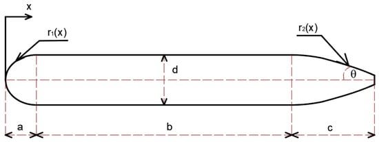
Figure 1.
Body shape of a torpedo.

Table 1.
Torpedo geometric parameters used for computation.
The three-dimensional (3-D) governing equations for the conservation of mass, momentum, turbulent kinetic energy, and its dissipation rate used to investigate the single-phase flow of seawater around the torpedo are written as:
where U = (u, v, w) is the velocity vector; is the dissipation of turbulent kinetic energy; ρ is the density of water; g is the acceleration of gravity; p is the pressure; μ is the fluid dynamic viscosity; k is the turbulent kinetic energy; μt is the turbulent viscosity; Pk is the turbulence production and is the affection of buoyancy; and YM is the contribution of pulsatile expansion incompressible turbulence. The values of the correlation constants are C1ϵ = 1.44, C2ϵ = 1.92, C3ϵ = 0.09, . The parameters μt, Pk, and are given as follows:
where is a dimensionless constant; is the rate of deformation.
The total pressure is estimated by:
where ps is the static pressure and pd is the dynamic pressure.
The total drag force includes the friction force caused by surface shear stress in the boundary layer and the pressure force generated by the pressure difference exerting on a torpedo body. Therefore, the total drag coefficient (Cd) and the lift coefficient ( are written as:
where Cdf is the coefficient of skin friction drag, Cdp is the coefficient of pressure drag, Fdf is the friction drag force that is caused by the roughness of the surfaces of the glider, Fdp is the pressure drag force, and Af is the submerged surface area of a torpedo body. The hydrodynamic lift force is expressed in terms of the dimensionless lift coefficient .
The fluid domain related to the boundary conditions is shown in Figure 2. The prescription of the boundary conditions for the fluid around a torpedo body is shown in Table 2. The parameters of the fluid (seawater) selected in the simulations are salinity S = 35 g/kg, temperature T = 15 °C, density ρ = 1027 kg/m3, and fluid viscosity μ = 1.25 mPa.s [40,41,42].
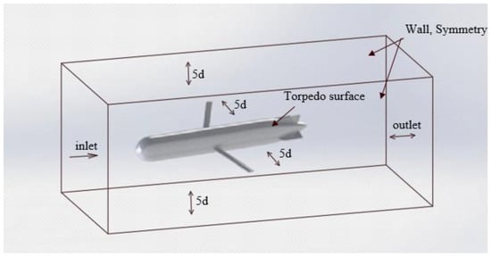
Figure 2.
A torpedo-shaped underwater glider and fluid domain for numerical computation.

Table 2.
Boundary conditions used for numerical computation.
2.2. Numerical Approach
The hydrodynamic characteristics of a torpedo-shaped underwater glider are numerically investigated by CFD simulations in the present study. For a challenging problem, the physical variables change significantly around the torpedo surface. A dense mesh must be located around the torpedo surface during the actuation process to guarantee the exact solution (Figure 3). It is very necessary to track the fine mesh moving simultaneously with the torpedo body. Therefore, the arbitrary Lagrangian–Eulerian (ALE) method is used to handle this problem. On the other hand, the 3-D governing equations with the relevant boundary conditions are solved by using the finite element method (FEM) with second-order Lagrange triangular elements. The dependency of the number of elements on the numerical results is determined to guarantee the exact solution. The poor quality of mesh elements can lead to collapse and inversion of the mesh, and elements could be wrapped inside-out or have zero volume. In this torpedo model, the mesh structure generated by a 3-D tetrahedral meshing technique is proposed. The finer mesh at the fluid-solid interface of the glider is carried out to ensure the accuracy of the numerical results [43].
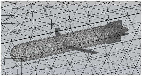
Figure 3.
The dense mesh around the torpedo surface used for computation.
3. Results and Discussion
The computational domain around the gilder is the water with the density (at 20 °C) = 1027 kg/m3 and the dynamic viscosity μ = 1.25 MPa.s. The maximum operational depth is 100 m, where the absolute pressure is about 105 Pa. The hull’s profile was improved several times. The numerical results are based on the circumstance that the glider moves in a forward direction with the velocity U = 1 m/s and angle of attack θ = −10°. The velocity fields, streamlines, and pressure distribution are presented in Figure 4. The wake region is located at the tail part of the underwater glider. In this simulation, the speed of fluid flow is set at 1 m/s, and the angle of attack is −10°. It reduced the strength of the wake that could be seen in Figure 4 based on the direction of arrows.
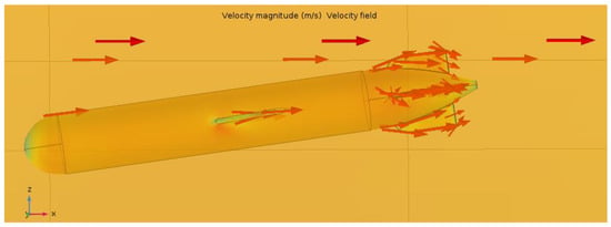
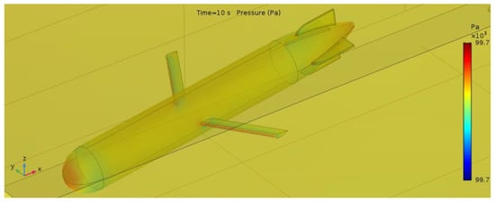
Figure 4.
The velocity fields, streamlines and pressure distribution with torpedo velocity U = 1 m/s and angle of attack θ = −10°.
To obtain the hydrodynamic characteristics of the underwater glider in this present work, the different glider velocities (from 0.9 m/s to 1.1 m/s) and angles of attack (−30°, −10°, −2°, 2°, 10°, 30°) are considered in this study. The numerical results of the drag and lift coefficients, flow behavior, force, and pressure distribution, which are computed using CFD analysis, are presented and discussed. Figure 5 demonstrates the pressure distribution at the tip of the nose at different torpedo velocities. From the present results, it can be seen that the tip of the nose is strongly affected by the fluid flow. During this period, the value of pressure at the bow of the glider slightly fluctuates around 10,000 Pa. This phenomenon should be noted to select the appropriate material in further studies. The contribution of the profile of the hull and wings is significant. While the wings of the glider mainly generate the lift force, the glider’s hull is one of the factors that create the hydrodynamic drag force of the glider’s body. Figure 6 shows the drag force acting on the glider body at the different velocities versus time. The drag force increases rapidly at the initial time and then approaches a constant as time goes on. The average lift force with the angle of attack θ = −10° at the different velocities of the glider is presented in Figure 7. The numerical results indicate that the higher the underwater glider velocity, the larger the drag force and lift force acting on the glider. Figure 8 gives information about drag and lift coefficients at five different values of glider speed. These coefficients are calculated by using hydrodynamic parameters obtained from the numerical simulations. As can be seen from the numerical results, the drag and lift coefficients decrease gradually when the glider velocity reduces. Table 3 indicates the average values of drag force, lift force, drag coefficient, and lift coefficient of the underwater glider at the different velocities when its angle of attack θ = −10°. The lift to drag ratio (L/D) at the different speeds of the underwater glider is presented in Figure 9. The numerical results indicated that the higher the velocity of the glider, the larger the drag and lift forces due to higher pressure acting on the glider body. It can be seen that the lift to drag ratio increased gradually when the glider velocity increases.
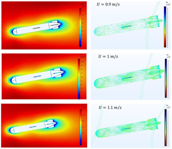
Figure 5.
Velocity (left) and pressure (right) distribution with the angle of attack θ = −10° at different speeds of the underwater glider.
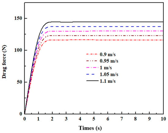
Figure 6.
Drag forces acting on the glider body with the angle of attack θ = −10° at the different velocities.
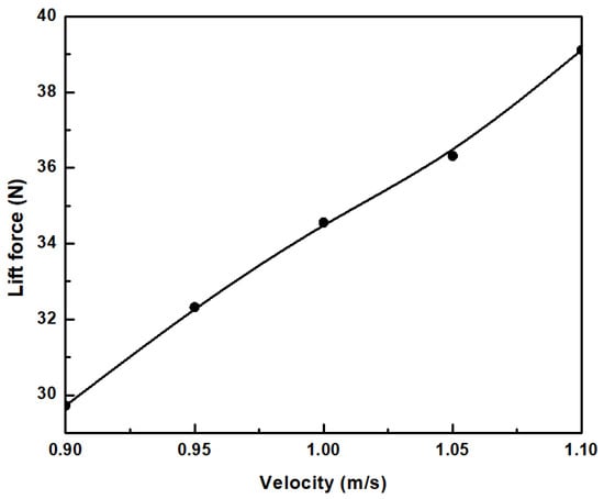
Figure 7.
The average lift forces acting on the glider body with the angle of attack θ = −10° at the different velocities.
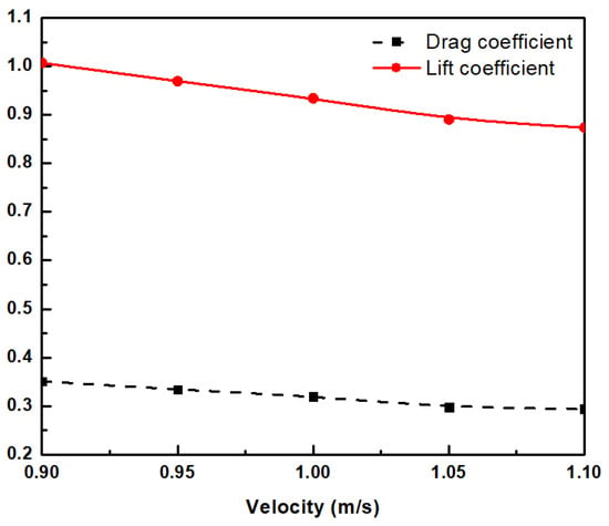
Figure 8.
Drag and lift coefficients curves for the underwater glider with the angle of attack θ = −10° at the different velocities.

Table 3.
Data obtained from the computation by using CFD for the different velocities of the glider.
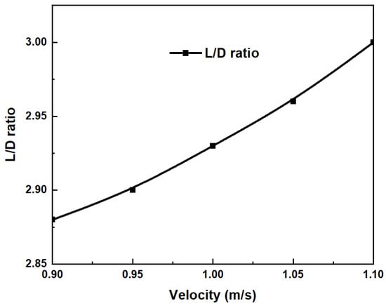
Figure 9.
Lift to drag ratio with the angle of attack θ = −10° at the different velocities.
Figure 10 illustrates the distribution of fluid flow around the torpedo-shaped hull with the glider velocity U = 1 m/s at different angles of attack, from −30 to 30°. The streamlines surrounding the glider’s body demonstrate good hydrodynamic performance. Based on the streamlines located after the body and the hull of the glider, the laminar boundary layer has been maintained as much as possible in all directions. Low hydrodynamic drag is considered to be a significant factor in the glider’s design. The magnitude of the skin friction, which occurs in the laminar boundary layer, is generated 5 to 10 times smaller than in a turbulent flow in the same condition. As a result, a glider with a natural laminar flow design can delay the turbulent transition, which reduces the pressure in the wake region. The pressure force and torpedo velocity are taken into account for the interaction between the fluid and the torpedo’s body. In this study, the maximum value of pressure is colored blue, which occurs at the tip of the nose of the vehicle and on the side of the hydrofoils. Its exact value is 97,700 Pa. On the other parts of the underwater glider, the pressure is not as high as the tip due to the smooth flow and the shape of the hull. The minimum pressure is located at the section that connects the nose and hull parts. The lift force depends on the angle of attack since its pressure distribution at the lifting body affects the magnitude of the lift force. When the attack angle increases, the magnitude of pressure generated by the lift force increases at the lift surface. Figure 11 shows the tendency of both drag coefficient and lift coefficient versus the angle of attack with the different velocities of the glider. At the angle of attack θ = 0°, the magnitude of drag and lift coefficients reaches its lowest point since the torpedo profile helps to increase laminar flow and reduce the drag force. The numerical results of the drag and lift coefficients show a good agreement with the experimental observation [11].
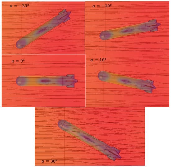
Figure 10.
Streamlines around the underwater glider with U = 1 m/s at different angles of attack.
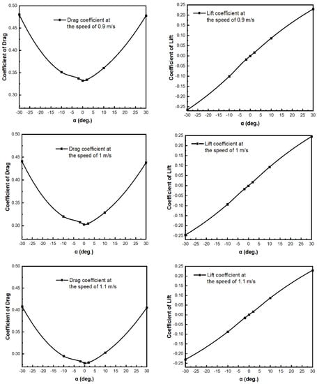
Figure 11.
The lift and drag coefficients versus the angle of attack at the different velocities of the glider.
4. Concluding Remarks
The hydrodynamic characteristics of a torpedo-shaped underwater glider are numerically investigated in this study. The design of an underwater glider based on Myring profile equations is to reduce the underwater resistance acting on the underwater glider body. The numerical results indicated that the nose of the underwater glider is subjected to a huge pressure when it moves through the water. The underwater glider velocity and angle of attack strongly affected the drag and lift coefficients. These present results are appropriate to reality and suitable to be used in further designs.
Author Contributions
Conceptualization, T.-L.L.; Data curation, T.-L.L.; Formal analysis, T.-L.L. and D.-T.H.; Investigation, T.-L.L. and D.-T.H.; Methodology, T.-L.L. and D.-T.H.; Project administration, T.-L.L.; Software, T.-L.L. and D.-T.H.; Validation, T.-L.L.; Writing—original draft, T.-L.L.; Writing—review & editing, D.-T.H. All authors have read and agreed to the published version of the manuscript.
Funding
This research is funded by Ho Chi Minh City University of Technology—VNU-HCM under grant number T-CK-2020-04.
Acknowledgments
We acknowledge the support of time and facilities from the National Key Laboratory of Digital Control and System Engineering (DCSELab), Ho Chi Minh City University of Technology (HCMUT), VNU-HCM for this study.
Conflicts of Interest
The authors wish to confirm that there are no known conflict of interest associated with this publication, and there has been no significant financial support for this work that could have influenced its outcome.
References
- Lurton, X. An Introduction to Underwater Acoustics: Principles and Applications; Springer: Berlin/Heidelberg, Germany, 2010. [Google Scholar]
- Leonard, J.J.; Bahr, A. Autonomous Underwater Vehicle Navigation. In Springer Handbook of Ocean Engineering; Springer: Berlin/Heidelberg, Germany, 2016; pp. 341–358. [Google Scholar]
- Niu, H.; Adams, S.; Lee, K.; Husain, T.; Bose, N. Applications of Autonomous Underwater Vehicles in Offshore Petroleum Industry Environmental Effects Monitoring. J. Can. Pet. Technol. 2009, 48, 12–16. [Google Scholar] [CrossRef]
- Cui, W. An Overview of Submersible Research and Development in China. J. Mar. Sci. Appl. 2018, 17, 459–470. [Google Scholar] [CrossRef]
- Sahoo, A.; Dwivedy, S.K.; Robi, P. Advancements in the field of autonomous underwater vehicle. Ocean. Eng. 2019, 181, 145–160. [Google Scholar] [CrossRef]
- Amiri, M.M.; Sphaier, S.H.; Vitola, M.A.; Esperana, P.T. URANS investigation of the interaction between the free surface and shallowly submerged underwater vehicle at steady drift. Appl. Ocean Res. 2019, 84, 192–205. [Google Scholar] [CrossRef]
- Myring, D.F. A Theoretical Study of Body Drag in Subcritical Axisymmetric Flow. Aeronaut. Q. 1976, 27, 186–194. [Google Scholar] [CrossRef]
- Mitra, A.; Panda, J.; Warrior, H. Experimental and numerical investigation of the hydrodynamic characteristics of Autono-mous Underwater Vehicles over sea-beds with complex topography. Ocean. Eng. 2020, 198. [Google Scholar] [CrossRef] [Green Version]
- Yu, P.; Wang, T.; Zhou, H.; Shen, C. Dynamic modelling and three-dimensional motion simulation of a disk type underwater glider. Int. J. Naval Arch. Ocean Eng. 2018, 10, 318–328. [Google Scholar] [CrossRef]
- Ziaeefard, S.; Page, B.R.; Pinar, A.J.; Mahmoudian, N. Effective turning motion control of internally actuated autonomous underwater vehicles. J. Intell. Robot. Syst. 2018, 89, 175–189. [Google Scholar] [CrossRef] [Green Version]
- Singh, Y.; Bhattacharyya, S.K.; Idichandy, V.G. CFD approach to modelling, hydrodynamic analysis and motion charac-teristisc of a laboratory underwater glider with experimental results. J. Ocean Eng. Sci. 2017, 2, 90–119. [Google Scholar] [CrossRef]
- Le, T.-L.; Chen, J.-C.; Shen, B.-C.; Hwu, F.-S.; Nguyen, H.B. Numerical investigation of the thermocapillary actuation behav-ior of a droplet in a microchannel. Int. J. Heat Mass Transf. 2015, 83, 721–730. [Google Scholar] [CrossRef]
- Le, T.-L.; Chen, J.-C.; Hwu, F.-S.; Nguyen, H.B. Numerical study of the migration of a silicone plug inside a capillary tube subjected to an unsteady wall temperature gradient. Int. J. Heat Mass Transf. 2016, 97, 439–449. [Google Scholar] [CrossRef]
- Le, T.-L.; Chen, J.-C.; Nguyen, H.B. Numerical study of the thermocapillary droplet migration in a microchannel under a blocking effect from the heated upper wall. Appl. Therm. Eng. 2017, 122, 820–830. [Google Scholar] [CrossRef]
- Le, T.-L.; Chen, J.-C.; Nguyen, H.-B. Numerical investigation of the forward and backward thermocapillary motion of a wa-ter droplet in a microchannel by two periodically activated heat sources. Numer. Heat Trans. Part A Appl. 2020, 79, 146–162. [Google Scholar] [CrossRef]
- Le, T.-L.; Tien, N.T. A CFD study on hydraulic and disinfection efficiencies of the body sterilization chamber. Ann. Roman. Soc. Cell Biol. 2021, 25, 3998–4004. [Google Scholar]
- Jia, L.J.; Qi, Z.F.; Zhang, S.; Qin, Y.F.; Shi, J.; Zhang, X.M.; Sun, X.J. Dynamic Analysis of the Acoustic Velocity Profile Obser-vation Underwater Glider. Appl. Mech. Mater. 2013, 475, 50–54. [Google Scholar] [CrossRef]
- Guang, P.; Hu, B.; Du, X.X.; Wang, Y.Y.; Pan, G. Research on Hydrodynamic Characteristics of Underwater Gliding UUV Based on the CFD Technique. Adv. Mater. Res. 2012, 479, 729–732. [Google Scholar] [CrossRef]
- Amory, A.; Maehle, E. Modelling and CFD Simulation of a Micro Autonomous Underwater Vehicle SEMBIO. In Proceedings of the OCEANS 2018 MTS/IEEE Charleston, Charleston, SC, USA, 22–25 October 2018. [Google Scholar]
- De Sousa, J.V.N.; de Macêdo, A.R.L.; de Amorim, W.F., Jr.; de Lima, A.G.B. Numerical analysis of turbulent fluid flow and drag coefficient for optimizing the AUV hull design. J. Fluid Dyn. 2014, 4, 263–277. [Google Scholar]
- Randeni, P.S.A.T.; Leong, Z.Q.; Ranmuthugala, D.; Forrest, A.; Duffy, J. Numerical investigation of the hydrodynamic inter-action between two underwater bodies in relative motion. Appl. Ocean. Res. 2015, 51, 14–24. [Google Scholar] [CrossRef]
- Dantas, J.; de Barros, E. Numerical analysis of control surface effects on AUV manoeuvrability. Appl. Ocean. Res. 2013, 42, 168–181. [Google Scholar] [CrossRef]
- Huang, H.; Zhou, Z.; Li, J.; Tang, Q.; Zhang, W.; Gang, W. Investigation on the mechanical design and manipulation hydro-dynamics for a small sized, single body and streamlined I-AUV. Ocean Eng. 2019, 186, 106106. [Google Scholar]
- Mansoorzadeh, S.; Javanmard, E. An investigation of free surface effects on drag and lift coefficients of an autonomous un-derwater vehicle (AUV) using computational and experimental fluid dynamics methods. J. Fluids Struct. 2014, 51, 161–171. [Google Scholar] [CrossRef]
- Cook, G.; Zhang, F. Mobile Robots: Navigation, Control and Sensing, Surface Robots and AUVs; Wiley: Hoboken, NJ, USA, 2020. [Google Scholar]
- Sarkar, T.; Sayer, P.G.; Fraser, S.M. A study of autonomous underwater vehicle hull forms using computational fluid dynam-ics. Int. J. Numer. Methods Fluids 1998, 25, 1301–1313. [Google Scholar] [CrossRef]
- Tyagi, A.; Sen, D. Calculation of transverse hydrodynamic coefficients using compuational fluid dynamic approach. Ocean Eng. 2006, 33, 798–809. [Google Scholar] [CrossRef]
- Jagadeesh, P.; Murali, K.; Jagadeesh, P.; Murali, K. Application of low-Re turbulence models for flow simulations past un-derwater vehicle hull forms. J. Nav. Arch. Mar. Eng. 1970, 2, 41–54. [Google Scholar] [CrossRef] [Green Version]
- Sakthivel, R.; Vengadesan, S.; Bhattacharyya, S. Application of non-linear k-ε turbulence model in flow simulation over un-derwater axisymmetric hull at higher angle of attack. J. Naval Arch. Mar. Eng. 2011, 8, 149–163. [Google Scholar] [CrossRef]
- Panda, J.P.; Warrior, H.V. A Representation Theory-Based Model for the Rapid Pressure Strain Correlation of Turbulence. J. Fluids Eng. 2018, 140. [Google Scholar] [CrossRef]
- Panda, J.; Warrior, H.; Maity, S.; Mitra, A.; Sasmal, K. An improved model including length scale anisotropy for the pres-sure strain correlation of turbulence. ASME J. Fluids Eng. 2017, 139, 44503. [Google Scholar] [CrossRef]
- Panda, J.; Mitra, A.; Joshi, A.; Warrior, H. Experimental and numerical analysis of grid generated turbulence with and with-out mean strain. Exp. Therm. Fluid Sci. 2018, 98, 594–603. [Google Scholar] [CrossRef] [Green Version]
- Mishra, A.A.; Girimaji, S. Linear analysis of non-local physics in homogeneous turbulent flows. Phys. Fluids 2019, 31, 35102. [Google Scholar] [CrossRef]
- Mishra, A.A.; Girimaji, S.S. Pressure–Strain Correlation Modeling: Towards Achieving Consistency with Rapid Distortion Theory. Flow Turbul. Combust. 2010, 85, 593–619. [Google Scholar] [CrossRef]
- Mishra, A.A.; Girimaji, S.S. Intercomponent energy transfer in incompressible homogeneous turbulence: Multi-point physics and amenability to one-point closures. J. Fluid Mech. 2013, 731, 639–681. [Google Scholar] [CrossRef]
- Mishra, A.A.; Girimaji, S.S. On the realizability of pressure-strain closures. J. Fluid Mech. 2014, 755, 535–560. [Google Scholar] [CrossRef]
- Mishra, A.A.; Girimaji, S.S. Hydrodynamic stability of three-dimensional homogeneous flow topologies. Phys. Rev. E 2015, 92, 53001. [Google Scholar] [CrossRef] [PubMed]
- Mishra, A.A.; Girimaji, S.S. Toward approximating non-local dynamics in single-point pressure-strain correlation closures. J. Fluid Mech. 2017, 811, 168–188. [Google Scholar] [CrossRef]
- COMSOL. COMSOL Multiphysics User’s Guide; COMSOL Inc.: Stockholm, Sweden, 2020. [Google Scholar]
- Joseph, A. Measuring Ocean Currents; Elsevier: Amsterdam, The Netherlands, 2014. [Google Scholar]
- Marsh, R.; Sebille, E.V. Ocean Currents; Elsevier: Amsterdam, The Netherlands, 2021. [Google Scholar]
- Brown, J. Ocean Circulation; Butterworth-Heinemann: Oxford, UK, 1989. [Google Scholar]
- Anton, A.; Cretu, V.; Ruprecht, A.; Muntean, S. Traffic replay compression (TRC): A highly efficient method for handling parallel numerical simulation data. Proc. Rom. Acad. 2013, 14, 385–392. [Google Scholar]
Publisher’s Note: MDPI stays neutral with regard to jurisdictional claims in published maps and institutional affiliations. |
© 2021 by the authors. Licensee MDPI, Basel, Switzerland. This article is an open access article distributed under the terms and conditions of the Creative Commons Attribution (CC BY) license (https://creativecommons.org/licenses/by/4.0/).