2. Past Work on Dilute Jet Flows
For a dilute jet expanding into a vacuum, the past work concentrates on two scenarios: with or without charges. The scenario without charges is more fundamental. Both flows are widely observed, e.g., plume impingement, in the astrophysical context, negatively charged dust particles in cometary tails expanding into the interplanetary space [
1,
2], or the expansion of the solar wind plasma into the wake region of inert objects, such as asteroids or the moon [
3]. Woronowicz [
4] described validation effort to assess the viability of applying a set of analytic point source transient free molecule equations to model behavior ranger from molecular effusion to rocket plumes. For numerical simulations, particle methods are widely used to simulate the second problem due to the complex physics. For example, the direct simulation Monte Carlo (DSMC) method [
5] is commonly adopted to simulate neutral gas flows, and the Particle-In-Cell (PIC) method [
6] for charged gas flows. For example, Roy, Hastings and Gatsonis [
7] proposed an asymmetric model of the plume and back-flow contamination from an ion-thruster plume, and performed hybrid PIC simulations to simulate charge-exchange efflux ions. We can only name a few.
Many past theoretical studies or modeling work focused on one-dimensional, unsteady flows, most of them adopted hydrodynamics approaches, and most of them provided flow and electric field results. Due to the complexities, it is challenging to obtain complete solutions for two-dimensional and three-dimensional flows and the results are scarce. In the past decade, thorough investigations (e.g., [
8,
9]) on the first problem with a gaskinetic method were performed. The planar scenario is illustrated in
Figure 1. A collisionless and neutral gas fires from a planar exit with a semi-height
H. At the exit, the gas has a number density
, a bulk velocity
, and a temperature
. The flow field can be represented either with a Cartesian coordinate system
, or equivalently a polar coordinate system
. Several key angles are defined in
Figure 1:
,
,
and
. A gaskinetic method was adopted, and the theoretical flowfield formulas include density
, velocity components
and
, and temperature
. The flowfield properties at a specific point
are:
where
,
,
There are two relations among them,
and
. The above results can be also written in a polar coordinate system
, which is more convenient for farfield flow solutions.
3. Potential and Farfield Approximations
One example for the second problem is electro-sprays in a vacuum condition, e.g., for space propulsion. The related flow stages for an electro-spray flow with ions and charged droplets [
10,
11] include a liquid meniscus, a Taylor cone, a cone-jet connection, a jet, a jet end (with a diameter of micro-meters) where ions evaporate into a vacuum, and form a final spray with a size of centimeters or beyond. The jet end is critical but it is rather small to be recognized in computational fluid simulations where usually the mesh size can not be micro-meters. As such, sub-grid modeling work on the jet end and plume flows must be done to resolve this issue. A recent paper [
12] has reported the development of such an axisymmetric model, and the purpose of this paper is to complete the counterpart model for a two-dimensional flow scenario. The fundamental assumptions are still the exit speeds are very high, and the local potential changes are very mild.
Translational temperatures. For high speed gaseous neutral plume flows, the local translational temperatures
and
along the stream and transverse directions can be quite different and their effects on charges can be quite different; hence, the analytical expressions for
and
are studied first. Following the same vein to obtain Equations (
1)–(
4), they are obtained and presented as follows:
As shown, there are “” and “” in the integrands, and the corresponding velocity components are different as well.
Potential and electric fields. It is well known that, plasma flows are described by the kinetic equation for the velocity distribution function
f for ions:
where
e is the unit charge, and
M is the ion mass. By comparing the 2nd and the 3rd terms in the above equation, under certain conditions, such as the velocity magnitude
is very large or the bulk velocity
is very large, and the change in local potential
is very mild, then the 3rd term is small and can be neglected. As such, the plasma flows can be treated as quasi-neutral gas flows, and it may be feasible to use the above gaskinetic approach to study the plasma plume flows.
In this work, we introduce the widely used Boltzmann relations for electrons in a quasi-neutral plasma flows:
where subscript
represents related reference values,
k is the Boltzmann constant, and
e is the standard electron charge. With almost the same amount of electron and ion number densities,
, and an ion and an electron have the same amount of charge and the same electric forces, a crude approximate condition
is obtained.
With the Boltzmann relation, the potential and temperature at the exit,
and
, are chosen as the reference values in Equation (
10), and the local density formula, Equation (
1) for
, is used to compute the local potential
. This is a direct and probably the simplest method, and the expression is:
From Equation (
11), with the aid of the Leibniz integral rule [
13], and chain rule for derivations, the corresponding electric field components at point
can be derived as:
Correspondingly,
and
can be derived as:
Far Field Properties. At a farfield point
in a Cartesian coordinate system, or
in a polar coordinate system, the distance to the coordinate origin,
is assumed to be much larger than the exit width,
, the angle is
, and the exit degenerates as one source point. The solid angle subtended by the point and the two exit lips,
, is quite small, and there are two following relations:
With these relations, the simplified number density, velocity components, temperature components, potentials, the electric field components, are derived from Equations (
1)–(
7). The results are listed as follows, with
:
where
A,
B,
C and
D are defined by Equations (
5) and (
8). They are not related with
, but they are functions of
.
The total current within the angle smaller than
is computed by Equations (
16) and (
17):
This formula indicates at farfield, the current within a certain angle
is constant.
The potential field is derived from Equation (
16) and the Boltzmann relation:
The electric field components in a polar or a Cartesian coordinate are:
and
have singular values at
, because in this model, no particle can move upwards along that line. Hence, the density along
is zero, resulting in a singularity for the potential due to the log function. This gaskinetic model shall be applied within a smaller angle range, for example,
.
Centerline Properties. With the relations, that
,
, the corresponding results are:
where
. Different from most past work by other investigators, the above results are relatively complex, but they are complete and compact. Crucial parameters,
and angles, are clearly included. They are obtained directly from the generalized accurate solutions.
4. Discussions and Farfield Property Validations
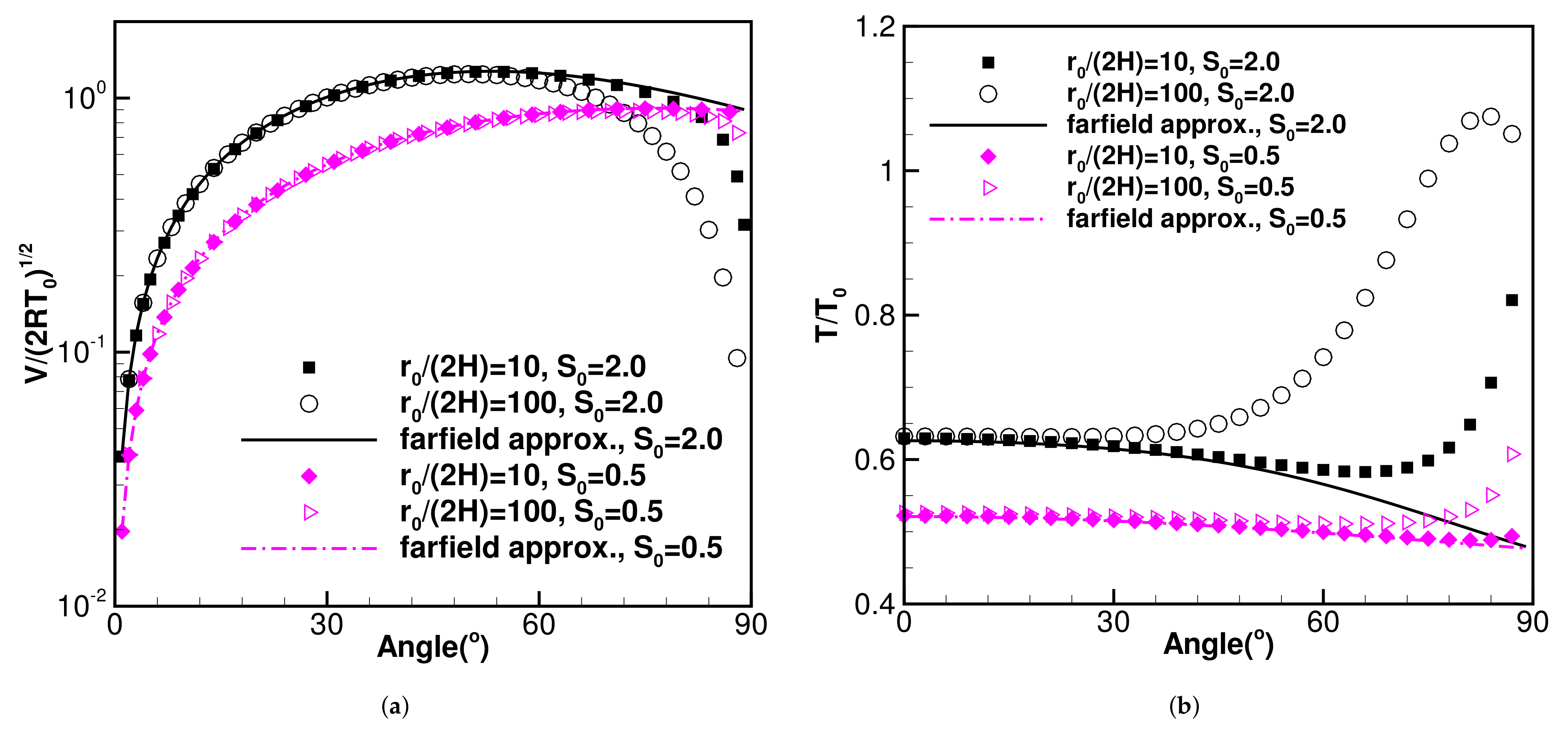
Figure 2a compares the density expressions, Equations (
1) and (
16), within an angle range
. Because Equation (
16) includes a factor of
, it is more convenient to plot and compare
. The exit speed ratios are set as
and
, the distance ratios are chosen as
and 100. The two curves in this figure are farfield approximations, described by Equation (
16), and the symbols represent the exact solutions, described by Equation (
1). As shown, results from the exact and simplified far field approximations are identical. With a higher exit speed ratio,
, the jet core further extends along the stream direction.
Figure 2b and
Figure 3a present normalized U- and V-velocity components, with the analytical expressions (Equations (
2) and (
3)) and farfield simplifications (Equation (
17)). It is also evident that at large angles, the exact and farfield approximations have larger discrepancies. The real situation is not so severe because the density at a large
is small, and the related V- momentum flux at a large
is quite small. Equation (
17) indicates the velocity components are closely related, and there is a relation,
. The exit is a point source, and particles from the exit can be considered shooting outwards without deflections.
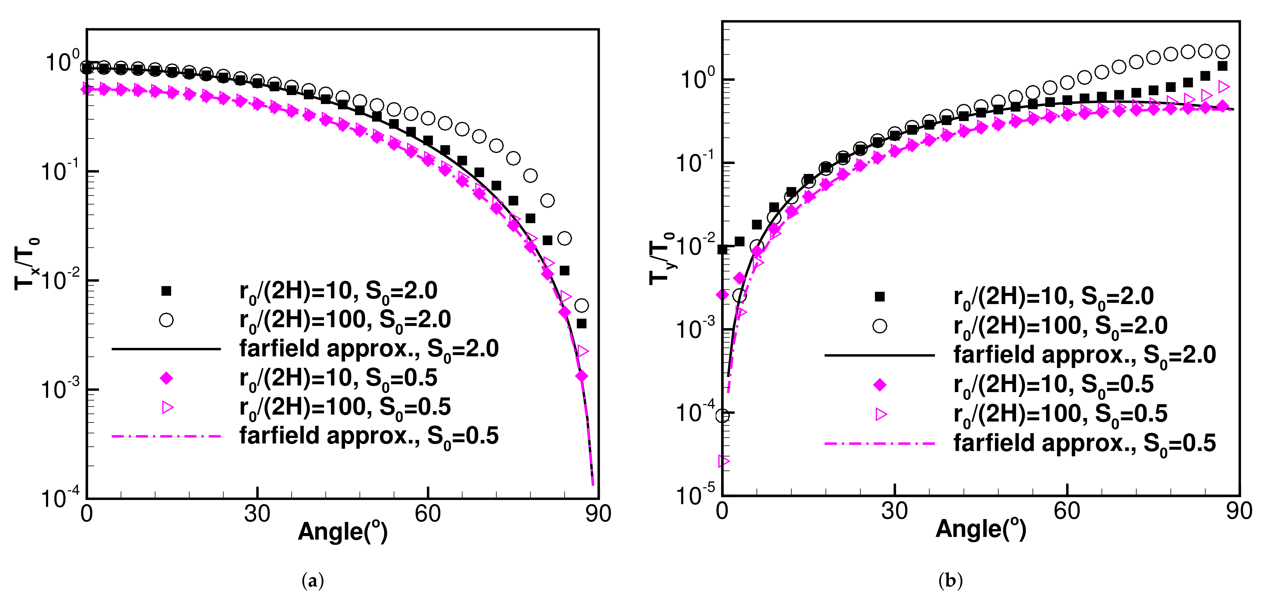
Figure 3b and
Figure 4a,b compare
,
and
, predicted by Equations (
4), (
6), (
7), (
18) and (
19). Within the jet core, the agreements among the analytical and the farfield approximations are satisfying, and with a larger angle
, the discrepancy increases. The largest discrepancy in
T is due to the related
which further traces back to the V-velocity component. However, for high speed plumes, for many situations, the plume core can be defined as a small region [
14] within
. As such, it is proper to utilize these temperature expressions to evaluate local temperature fields.
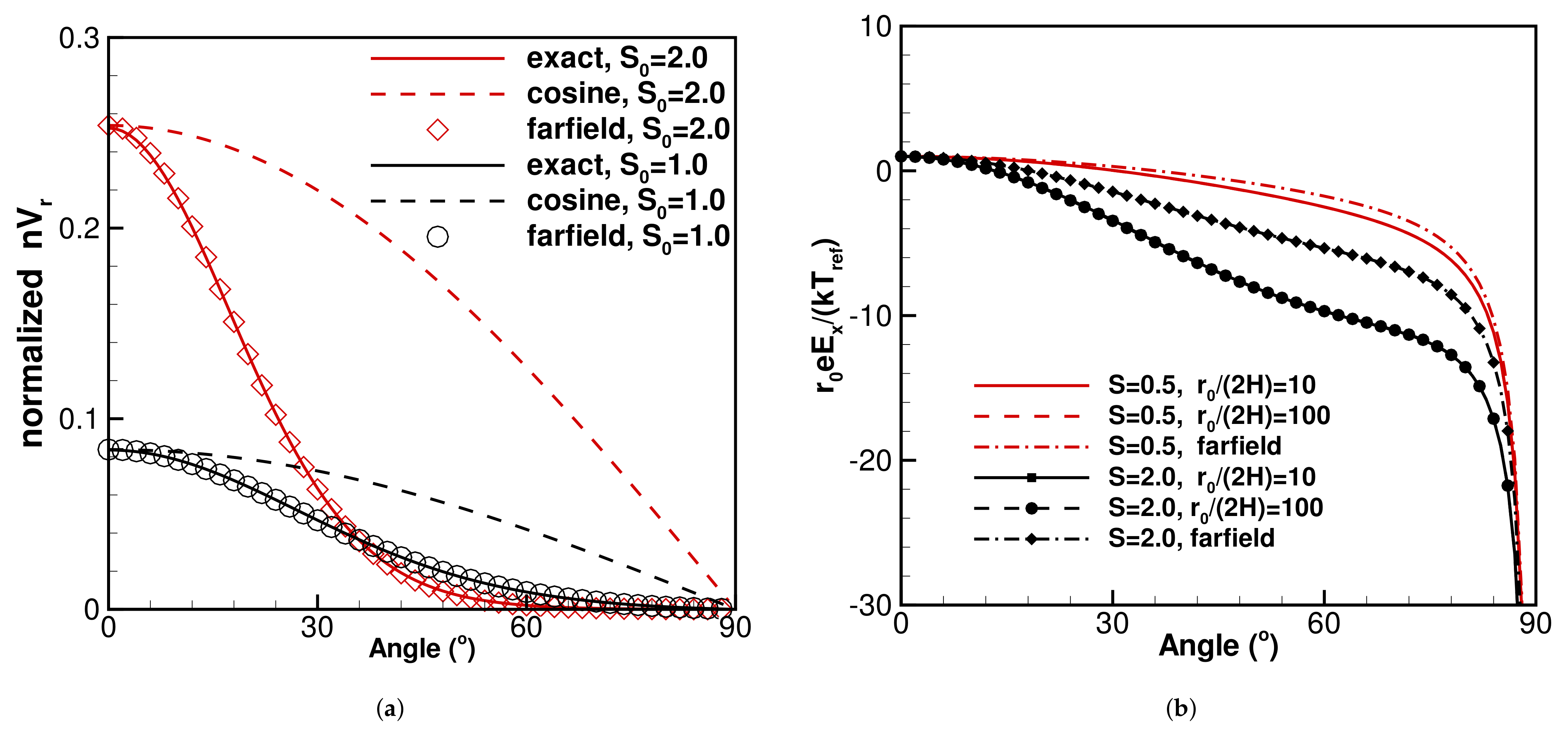
Figure 5a shows normalized farfield number density flux
at a constant radius
. The profiles are similar to those for density and but this property is more helpful. In general, the profiles are steeper at the centerline because the centerline velocity is much larger.
Figure 5b shows the normalized exact and farfield electric field component along the X-direction, at locations
and 100, and
and 2.0, correspondingly. The curves are computed with Equations (
12) and (
22). For the exact solutions and specific
value, the solutions for
and 100 coincident. There are appreciable difference between the exact and farfield approximations, and the deviations depend on the
values. However, there is no doubt that they share the same trend.
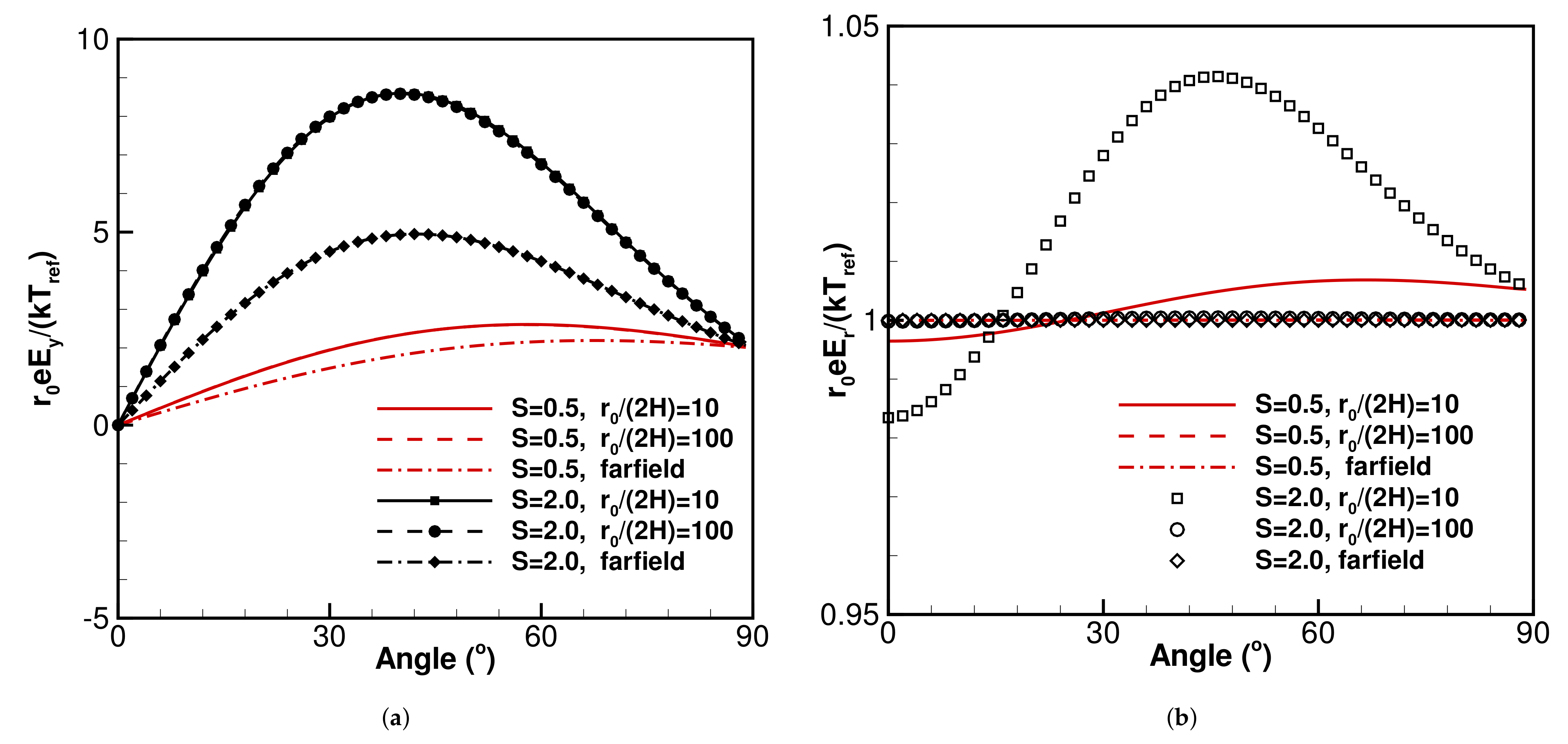
Figure 6a shows farfield electric field component along the Y-direction, at locations
and 100, and
and 2.0, correspondingly. The curves are computed with Equations (
13) and (
22). Similar patterns to the
direction results, about the deviations and the same trends are evident.
Figure 6b presents the normalized farfield
variations. It includes six curves with different exit speed ratios
and 2.0,
and 2.0, Equations (
14) and (
22) are used for computation. As shown, the variations are very small, close to the unity as they shall be. As shown, at a location relatively closer to the exit,
, the
and
curves are slightly different from the unit value of 1.0. At a place relatively far away from the exit,
and farfield, the values are unit as described
Figure 6a.
Equations (
16)–(
22) can be used to quickly estimate the farfield properties, and the crucial factors are the specific speed ratio,
, and the geometry locations. A calculator may be sufficient to compute a farfield property, and there is no need of a particle simulation. However, it shall be kept in mind that those farfield simplified solutions are the approximations to the exact solutions—certain deviations may exit.
The results in this work can conveniently explain many experimental measurements as well. More accurate analysis is needed in the future to better explain the plasma plume flow results because the current work is for jet from a planar slit or a crack, while the plasma plume flows in space are axisymmetric from a round exit.
In the end, we want to explain the relations between this paper and another recently published paper [
12]. Both focus on highly dilute slightly charged jet out of an exit; this paper is scenario from a planar exit, and the other is the scenario from a planar exit. The latter [
12] includes more details and can aid readers understand the work. For highly dilute neutral gaseous jets out of an exit, there are another two past papers [
8,
9] which can help understand the work presented in this work—the first one is from a planar exit, and the other is from a round exit.
5. Conclusions
The work concentrated on the electric fields related with highly rarefied weakly ionized gas. The work is based on collisionless neutral gaseous jet and the Boltzmann relation. The analytical solutions and approximate expressions at farfield (i.e., large ) are derived and are compared.
The simplified far field solutions illustrate insights which is not evident in the corresponding exact solutions. For example, Equation (
17) indicates at farfield the streamlines are straight, and the two components are constant; however, the corresponding exact solutions, Equations (
2) and (
3), can not offer such information.
Evidently, this new model offers a full set of exact solutions to the flow and electric fields in front of a nozzle, we shall keep in mind that they are based on neutral gas solutions, and the simplest potential relation, i.e., the Boltzmann relation is adopted to aid the study. This model is crude; however, thorough validations can be performed in a systematic manner in the future.


