Article

Numerical Study of Heat Transfer and Speed Air Flow on Performance of an Auto-Ventilated Disc Brake

by
R. A. García-León
*,
N. Afanador-García
and
J. A. Gómez-Camperos
Facultad de Ingeniería, Universidad Francisco de Paula Santander Ocaña, 546552 Norte de Santander, Colombia
*
Author to whom correspondence should be addressed.
Fluids 2021, 6(4), 160; https://doi.org/10.3390/fluids6040160
Submission received: 12 March 2021 / Revised: 9 April 2021 / Accepted: 13 April 2021 / Published: 16 April 2021
(This article belongs to the Special Issue Advances in Thermo-Fluid Dynamics of Industrial Systems)

Abstract

:
In the braking system, the heat dissipation generated by the friction between the disc and pad should be evacuated as quickly as possible. In this work, five common different automotive disc brakes were studied through mathematical theories of heat transfer and numerical methods using the ANSYS software. In addition, a direct comparison between experimental, theoretical, and simulation values found in the open literature was performed to propose a disc brake with an improved geometry in terms of dissipation of heat transfer. The numerical results were considered to propose two possible solutions of disc brake geometries using N-38 ventilation blades used in aeronautic engineering. An improvement in temperature dissipation was achieved by approximately 23.8% compared to the five geometries analyzed with a simple type N-38 ventilation blade. The heat dissipation in the brakes strongly depends on the geometry of the disc, the geometry of the blades, the material from which it is manufactured, the material of the pad, the weight of the vehicle, and the operating conditions, as can be verified with mathematical calculations and experiments. The results obtained demonstrate that the discs can be used effectively in extreme working conditions (80 km/h and 33°C), without affecting the safety of the occupants and the braking system.

1. Introduction

Brakes are essential elements to maintain maneuverability and safety in any vehicle, whether they are rotary or linear. Braking systems work by taking advantage of the friction between two surfaces (the disc and the pad), to slow down the moving vehicle. There are various types of brakes: drum, band, disc, and conical, and they have different applications. In particular, the most common ones in the automotive sector are the self-ventilated disc type in the front part of the vehicle and the drum type for the rear part [1]. Disc brakes differ from the other types as the applied force is normal to the disc instead of being radial. Another distinctive feature of the disk brakes is that the friction moment does not aid the actuation moment (self-energizing effect), as occurs in drum and bevel brakes. This allows slight changes in the friction coefficient to not dramatically affect the braking force required to stop the car. For example, a 30% variation in the friction coefficient, which is a normal condition in humid environments, causes at least a 50% increase in the force of the braking system [2].
The disc brake is the element that is attached to the wheel hub and rotates with it, forming the mobile element of the braking system. Against the surface or friction area of the disc brake the pads interact, and thus the vehicle is stopped thanks to the continuous friction established between the pads and the disc. During this process, the hydraulic pump is activated when actuating the brake pedal, which transports the brake fluid to its calipers. The pressure transmitted by the liquid causes the caliper piston to push the pads against the disc brake generating friction. The kinetic energy (accumulated in the vehicle due to its speed) is transformed into thermal energy due to the friction between the disc and pad, which is evacuated by natural convection to the environment; thus, the vehicle gradually decelerates. In this way, it is normal in vehicles to use self-ventilated brake discs in all four wheels (discs with ventilation channels). However, the safety triangle intervenes, which refers to the components of the vehicle that influence the movement, such as the shock absorbers, the braking system, and the tires [3,4]. The efficiency of the braking process depends significantly on the type of material, the disc geometry, and the ventilation blades’ configuration for heat dissipation.
In conclusion, the braking system is a device directly coupled to the vehicle tires, whose main objective is to transform the kinetic energy of the vehicle into thermal energy to totally or partially reduce its speed. Likewise, the bigger the vehicle, the greater its mass; therefore, more effort is made by the braking system to reduce the kinetic energy caused by the movement [5]. This generates an increase in the temperature of the braking system in many cases.
The study conducted by Wallis et al. [6] evaluated the thermal behavior of three types of rotors: straight radial blades (SRV), straight blades with a rounded edge (SRV-R), and with teardrop-shaped diamond blades (DTDP). They concluded that the capacity of heat transfer of round edge straight vane rotors (SRV-R) and teardrop diamond vane rotors (DTDP) is ~20% higher than that of straight radial vane rotors (SRV). This is because of the improved pumping in the rotors for this configuration, evidencing the importance of the design in the geometry. McPhee and Johnson [7] evaluated heat transfer and fluid movement using a transient-state experiment to quantify the internal convection between the ventilation vanes in terms of external convection (rotor surface) for three different speeds. The results showed that conduction and radiation were negligible. On the other hand, for higher rotor speeds, the heat transfer by convection increases, showing a linear relationship. The flow analysis of the experiment involved the determination of the speed field through the internal passages formed by the radial of the disc brake [8]. Atkins et al. [9] studied the local temperature and the experimentally obtained distributions of the heat transfer coefficient on the internal surfaces of a rotor brake with rotating blades at realistic angular velocities. The results validated that the bulk of the airflow within the vented channel of a rotating disc flows mostly backward from the ventilation blades, and the internal heat transfer is distributed non-uniformly during the motion. In addition, the outer surfaces of the disc brake generate an average cooling of approximately twice that of the inner surface.
Park et al. [10] carried out a study to increase the heat transfer rate in the ventilated disc brake. The surface geometry in the disc brake flow path was modified from a smooth surface to a surface with helical grooves. The results of the numerical analysis showed that the local Nusselt numbers decreased monotonically with the distance between the crests and the helical groove. This shows that the increase in the surface area provided by the helical grooved geometry improves the recirculation behavior of the airflow and the swirls formed. Therefore, when the helical groove is too deep, it causes the rate of heat transfer to decrease.
To demonstrate the numerical simulation of steady-state braking, Nejat et al. [11] modeled the various airflow geometries by simulation of computational fluid dynamics (CFD). Furthermore, some detailed analyses for the speed and temperature distribution around the ventilation blades were made. The result of the CFD analysis showed an increase in the airflow, limiting the flow separation region, especially near the leading edge of the ventilation blades. These factors are essential in the overall improvement of the heat transfer coefficient (HTC). Likewise, a new design was introduced using two air blades, which notably increased the airflow efficiency, improving the HTC between 17 and 29% for different angular speeds.
Duzgun [12] modeled three different ventilated disc brakes employing finite element analysis (FEA) to study their thermo-structural behavior. The FEA results showed that heat generation on the solid surfaces of the brake discs is reduced to a maximum of 24% due to the geometries of the ventilation blades. The experimental study for the dissipation of heat generated on the discs’ surfaces was verified through the FEA and a range between 1.13 and 10.87% was found for the analysis of the temperature. This behavior aided in the improvement of the braking performance, maintaining the friction coefficient between the pad and the disc surface and stabilizing the pads surface wear rate, especially under continuous braking conditions.
Lee et al. [13] numerically analyzed the fluid flow and heat transfer characteristics of ventilated disc brakes under real conditions. Due to higher heat dissipation compared to drum brake or solid brake discs; the results showed that when the incoming cooling air collides with the ventilation blades the airflow is deflected due to the Coriolis force. In addition, reverse airflow is generated, which has a negative influence on heat transfer. The inverted airflow for all cases is identified close to the suction side of the blades, obtaining conclusions and comparisons between different blade configurations to propose an alternative model.
Belhocine and Afzal [14] carried out a transient thermal analysis of two types of disc brakes, one solid and one ventilated. This analysis was performed using the finite element method (FEM). During the braking process, the material must have a lower thermal conductivity, which generates large thermal gradients and, consequently, an increase in the disc brake surface temperature. From the results obtained by FEM, the ventilated disc brakes made of FG20 and FG25AL will have temperatures around 351.5 to 380.2 °C, respectively. These are higher than that of the ventilated disc made of FG15, which has a maximum temperature of 345.4 °C. Therefore, the most suitable material in this case for the brake discs is FG15 gray cast iron, since it presents the best thermal performance. Belhocine and Bouchetara [15] analyzed the thermal behavior of the solid and ventilated brake discs of automotive vehicles using the ANSYS simulation software. The temperature distribution in the disc brake was modeled to identify all the factors and the corresponding input parameters at the time of braking operation, such as the type of braking, the geometric design of the disc, and the material used. The study concluded that FEA presents satisfactory results, compared to those of the specialized literature.
Through the particular manufacturing process of the Si C 3 D/Al alloy, Jiang et al. [16] carried out thermal and stress analysis on the disc brake during emergency braking with a speed of 350 km/h. The authors considered the cooling air using FEM and computational fluid dynamics (CFD). The alloy improved the temperature generated by friction by 14% (517 °C and 192 MPa in 63 s) due to its high thermal conductivity. Topouris et al. [17] conducted an experimental investigation on the heat dissipation of stationary brake discs concentrated on four disc designs: a ventilated disc with radial blades, two ventilated type discs with curved blades (a non-perforated and cross-drilled disc), and a solid disc. The experiments were performed on a specially designed thermal spin platform and provided accurate, repeatable, and reliable temperature measurements to predict total, convective, and radiative heat dissipation coefficients. The values obtained were compared with the results obtained through CFD, and thus the four disc brake designs show that the disc with radial blades has the highest convection heat dissipation. It was around 30% lower compared to the solid disc. Lakkam et al. [18] investigated the temperature gradient of the disc brake to evaluate the heat convection coefficients (h) through experimental and numerical tests. The value of h was modified by changing the temperature distribution in disc brakes under steady-state forced heat convection. Numerical and finite methods were applied to study the distribution and dissipation of heat transfer, and the results obtained were validated by the experimental results.
To provide a broader perspective on the behavior of the brake discs, García-León [19] selected three classes of commonly used disc brakes to perform mathematical and simulation calculations for evaluating the behavior of each disc geometry. The results showed that the discs with a superficial temperature higher than 80 °C could dissipate the heat in 40–60 min through natural convection and airspeed air in the surroundings equaled to zero. Likewise, García-León and Flórez-Solano [20] studied the dynamics and kinetics of the brake system with the mathematical calculation of the pedal to simulate the behavior through FEA with the aid of the Solidworks simulation software. The results of their simulations showed that the geometry of the ventilation blades is an essential point for the design of disc brakes. García -León and Flórez-Solano [21] analyzed under different theories of heat transfer the evacuation of the heat to the surroundings (air) for three different disc brakes. The brake discs work under two types of movement, rotational and translational. The first is generated by the engine and transmitted by the axles to the wheels, and the second is the movement that the vehicle creates when moving. Therefore, different types of heat transfer by convection occur at the same time. Using CFD in the Solidworks simulation software, the distribution of heat transfer by convection in a disc rotating at high temperature through a horizontal airflow duct was studied, obtaining the behavior of the speed and temperature inside the ventilation blades, along with the geometry of the three brake discs.
On the other hand, García-León et al. [22] proposed a new geometric arrangement to improve airflow in a vehicular disc brake, considering the ventilation blades based on NACA 66–209 type aerodynamic profiles. To validate this design proposal, they constructed a 1:1 prototype with the aid of additive manufacturing. To calculate the speed field produced in the suction and discharge area, they designed a structure for the disc and a particle image velocimetry (PIV), the speed field produced in the suction and discharge areas. The validation of this geometric design was developed under five levels for the angular velocity: 541, 641, 741, 841, and 941 rpm. These are proportional to the linear speeds of the vehicle at 60, 70, 80, and 90 km/h. Numerical tests were performed with three different quantities of ventilation blades, which were 10, 15, and 20. They proved that a configuration of 20 blades improves heat dissipation [23,24]. A similar study proposed a new geometric arrangement to enhance the airflow in a vehicular disc brake, considering the ventilation pillars based on N-38 type aerodynamic profiles. It was evidenced that as the speed of the vehicle increases, the suction force is greater, that is, the test length is shorter for each one. In addition, for a higher speed, the airflow counteracts the amount of heat generated at the moment of braking, as there is more energy to reduce [25].
Hwang et al. [26] studied the behavior of the disc brake surface temperature during single-stop braking, finding that the temperature rises more in the brake ventilation wall. The results were validated through the 3D model of the ventilated disc brake through a transient thermal analysis. Likewise, the results evidenced the importance of the ventilation blades’ geometry on the performance efficiency during heat dissipation, being compared to experimental results. Volchenko et al. [27] found that one way to increase the forced air and the cooling intensity of the disc pad friction torques during vehicle movement is by increasing the area of the disc brake ventilation blades. Whereas, if the ventilation blade area increases by approximately 20%, the cooling intensity increases by 7 to 10%.
On the other hand, different factors are involved in the efficiency of the braking process, such as the amount of energy in the disc, the speed of heat dissipation, the efficiency of the disc geometry, among others. Those can be evaluated by applying mathematical concepts or numerical simulations [2,28].
This study presents the thermal and fluid dynamic behavior of two geometric proposals of automotive disc brakes. There are not enough open investigations reported in the literature about the geometry study of the ventilation blades in the disc brakes and their heat dissipation behavior [29]. The results are analyzed through heat transfer laws, mathematical concepts (conduction and convection phenomena), and the FEA to select a new geometry considering five different disc brake ventilation blades studied by different authors. Finally, the heat generated by friction on the disc brakes is modeled via CFD as a way of designing disc brakes, improving the braking process’s performance, safety and providing a better theoretical basis to evaluate the heat dissipation and the disc fluid dynamic behavior.

2. Materials and Methods

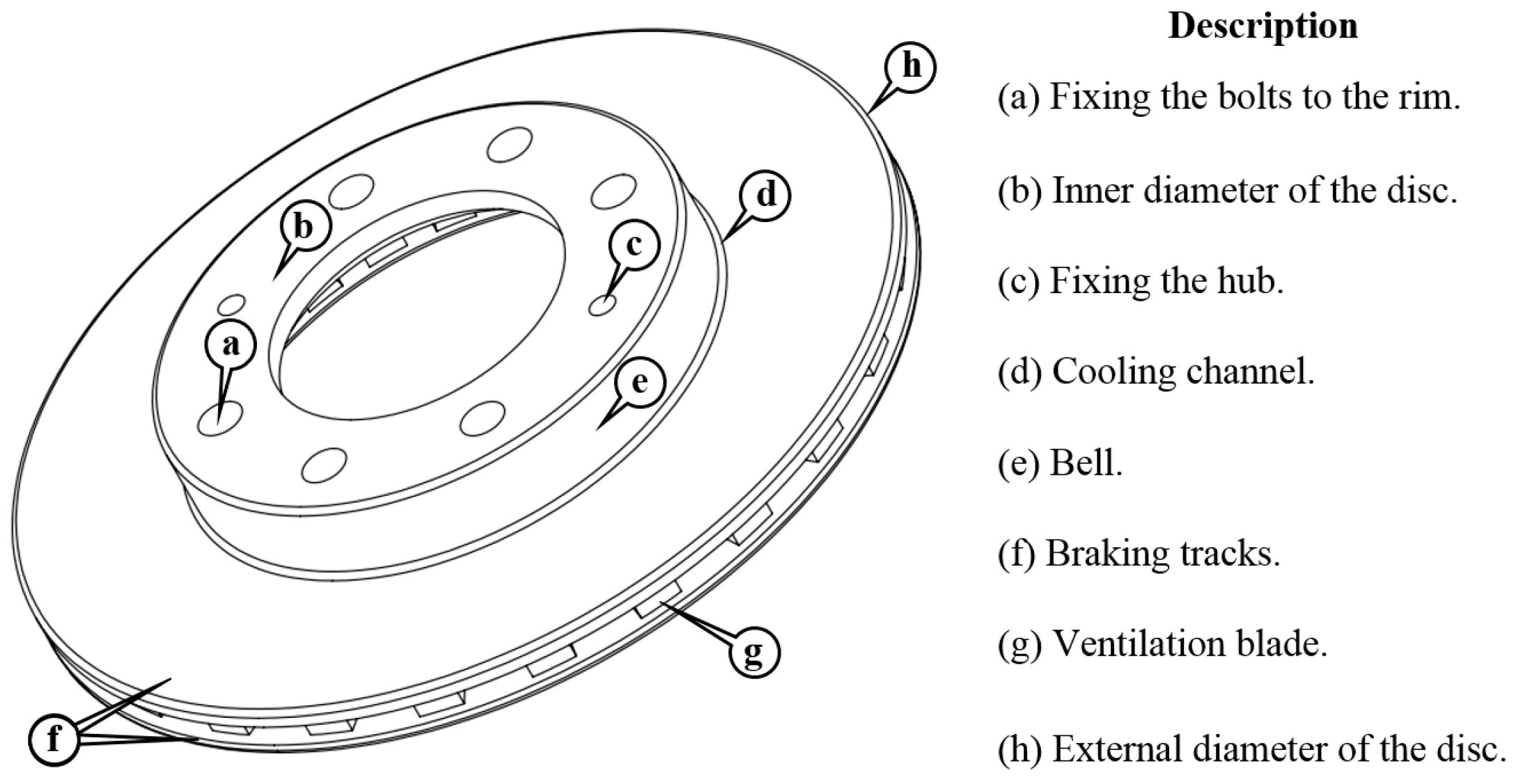
2.1. Auto-Ventilated Disc Brake

This type of disc has radial channels in the middle of the friction surfaces. In such a way that an air current is produced in the middle of the frictional area to improve the dissipation of the heat generated during breakings. These discs can be used on the front and rear wheels as they are designed to withstand up to 700 °C. If the vehicle has ventilated and solid discs, the ventilated ones will be located on the front axle since the most significant braking force falls on them [5].
The brake disc is formed by a round shape with a large surface that is exposed and ventilated. This enables successive cooling and therefore allows all the heat produced caused by friction to be dissipated. Figure 1 shows the main parts of a disc brake.
Gray cast iron receives its name for the appearance of its fracture surface, which is gray in color. Carbon is commonly found in the form of lamellar graphite and usually contains approximately 1 to 3.8% silicon. In pearlite gray cast irons, the carbon is combined to produce cementite and the free part in the form of graphite. It should be noted that in practice it is too difficult to obtain castings in which all the carbon is manifested in the form of graphite. Gray cast iron differs from steel because there are graphite inclusions on its structure with extensive variations in quantity, shape, size, and distribution. This gives rise to different gray cast iron that is a composite material of graphite with a matrix that is regularly composed of cementite and ferrite [30].
The mechanical, physical, and thermal properties of gray cast iron to perform mathematical and numerical calculations are summarized in Table 1.

2.2. Disc Brakes Geometry

Table 2 shows the geometries of the disc brakes studied together with the specifications used in the mathematical and numerical analysis.

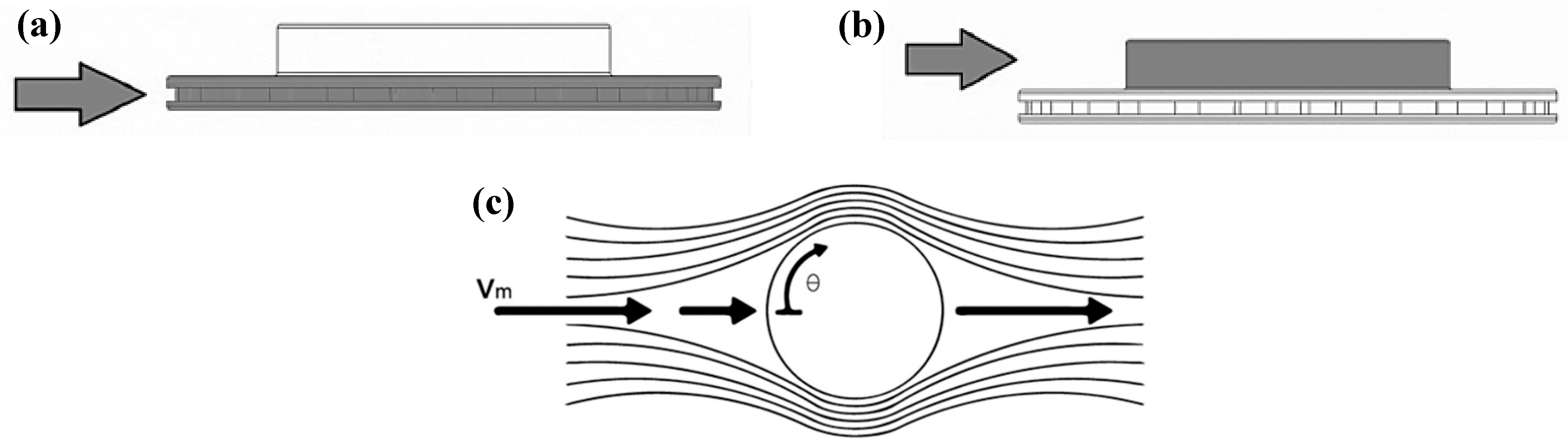
2.3. Mathematical Calculations

The dynamic and thermal analysis of the brake system was made starting from the calculation of the particles in motion to later determine operating conditions based on the mass of the vehicles and the geometries of the disc brakes. The mathematical calculations and the theories of heat transfer were considered as proposed by Garcia-León et al. [20,21,35].
The braking force is the one that the driver exerts on the brake pedal to stop the vehicle. The efficiency of that process depends on the force applied to the pedal. In many cases the driver cannot exert enough force to stop the vehicle at the ideal distance; so, the force is multiplied through levers or hydraulic circuits to obtain a greater friction force. During real braking conditions, it is difficult to achieve the maximum braking force on all four wheels of the vehicle simultaneously due to the weight distribution on the vehicle (affected by passengers, road inclination, undulations, among others), and this determines its limit of adhesion that varies dynamically during the braking process. The weight distribution on the wheels is not constant, and the operating conditions change every fraction of a second. On the other hand, the conditions of mathematical and experimental calculations are considered suitable.
The kinetic and potential energy of the vehicle generates the power of the system, which is transformed into thermal energy generated by the operating conditions. The energy accumulated in the disc brake in the form of heat due to the friction between the brake and the pad must be dissipated as quickly as possible to avoid overheating. The heat transfer rate depends on the geometry of the disc brake, its material, and the operating conditions.
The heat generated must be evacuated as quickly as possible so repetitive braking does not generate high temperatures that could lead to reduced efficiencies and lower safety in the braking process. The vehicle displacement aids the heat dissipation through the phenomena of convection and radiation. The braking efficiency is the magnitude of the braking system performance, where the vehicle must stop at a required time and distance, according to the operating conditions and the force applied on the brake pedal. The efficiency of the braking system is considered to reach 100% when the measured deceleration is equal to the acceleration due to gravity (9.8 m/s2).
During the braking process, the disc absorbs approximately 90% of the wheel energy and the pad absorbs 10%, according to theoretical assumptions [1,12]. In this way, Equation (1) was used to calculate the total energy in the disc brake.
E Total   in   disc = E Each   disc × 0.9  
The rise in temperature of a brake assembly is mathematically governed by Equation (2), and to calculate the temperature on the surface of the disc, Equation (3) was used [8].
Δ T = E Disc   brake m D × C p
T i T = Δ T  
Equation (4) is known as Newton’s law of cooling, which states that a disc at a temperature Ti (the instantaneous temperature at all times) will cool by natural convection if it is left at room temperature for a particular time. This equation helps to determine the instantaneous temperature until the disc cools down, which will depend on the geometry of the disc brake and its material. The results of the cooling calculation were carried out using the properties summarized in Table 1.
T i T = ( T i T ) × e A × U m D × C p × t
For the calculation of the heat transfer coefficients (h), the disc brake geometries were considered. The thermal convection and transfer coefficients generated on the disc brakes were calculated for a speed peak of 80 km/h and with common air physical properties reported by Cengel [36]. The total convection generated during the braking process is a sum of the frontal convection (bell and periphery), lateral convection, rotary effect convection, and ducts convection, based on each disc brake geometry. For these estimations, Equations (5) and (6) were used.
h = K D × Nu  
h Total = h Frontal   convection + h Lateral   convection + h Rotary   effect   convection + h Ducts   convection
To estimate the convection, the Reynolds number expressed in Equation (7) is used. The automobile speed is 80 km/h ≌ 22.22 m/s, the environment temperature is T∞ = 33 °C, and the diameters of the different disc brakes studied can be found in Table 2 [37].
R e = V   × D υ
Frontal convection is performed between braking tracks/bell and the air and is represented as the sum of the peripheral convection (Figure 2a) and the bell convection (Figure 2b) of the disc. To determine the air properties, it was necessary to obtain the average temperature using Equation (8).
T P = T + T i 2
The rotary convection appears between the disc brake and the airflow. Figure 2c represents how the airflow convection wraps up the disc brake contour, where it develops a boundary layer that surrounds the disc. Air particles collide with the disc generating an increase in the pressure inside the disc. To obtain this calculus, it is necessary to calculate the Reynolds number for rotary convection using Equation (9).
Re g = D 2 × ω υ  
Lateral convection occurs thanks to the air flux on the disc walls (Figure 2d). In this case, the airflow on the flat plates is studied. Notice that the transmission from laminar to turbulent flow depends on the surface’s geometric configuration, its roughness, and the fluid circulating on the disc. The Reynolds number varies along the stream until it reaches the end of the plate. It can be considered that the transmission from laminar to turbulent flow has to be given a critical Reynolds number that is estimated using Equation (7).
Duct convection happens inside the ventilation blades, as shown in the schematic representation in Figure 2e. In this case, the ducts on the disc were considered as non-rounded with two walls. Besides, the geometries of the ducts were considered to estimate the inlet and outlet speeds and the angles using the theory of radial fans from the book mechanics of fluids and hydraulic machines.
In this way, the heat transfer only was calculated by the convection effect, using Equations (10) and (11) respectively [38].
Q ˙   = h × A s × ( T i T )  
Q Total   in   disc = Q Bell + Q Peripheral + Q Rotary
The heat dissipation of the disc brake is mainly attributable to the action of the convection coefficient. When temperatures of at least 300 °C are generated in the braking process, the radiation coefficient acts to dissipate the heat. The calculations developed at 80 km/h do not generate enough heat on the braking area for the radiation to act. This also depends on the material properties of the disc brake [39,40].

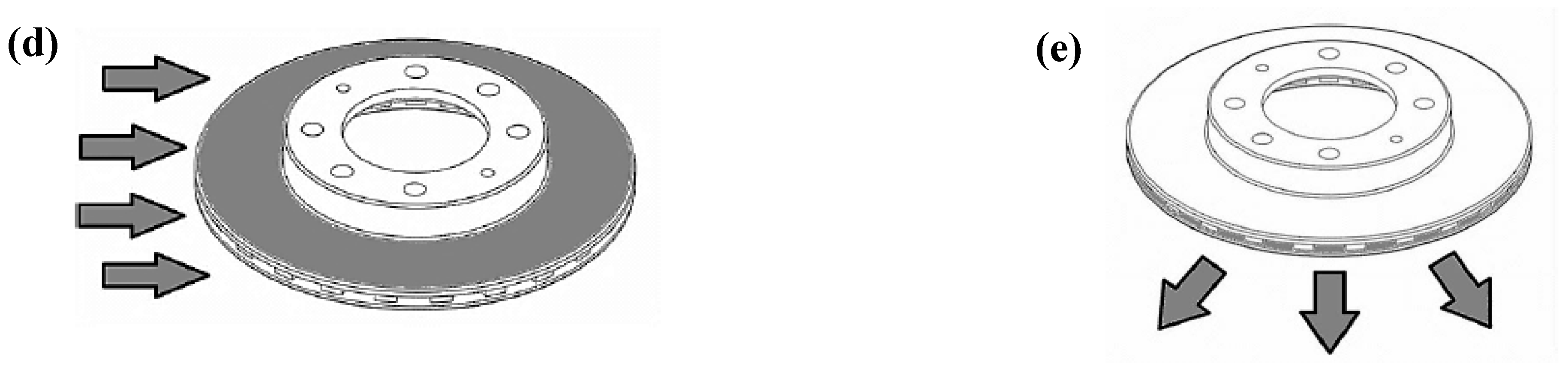
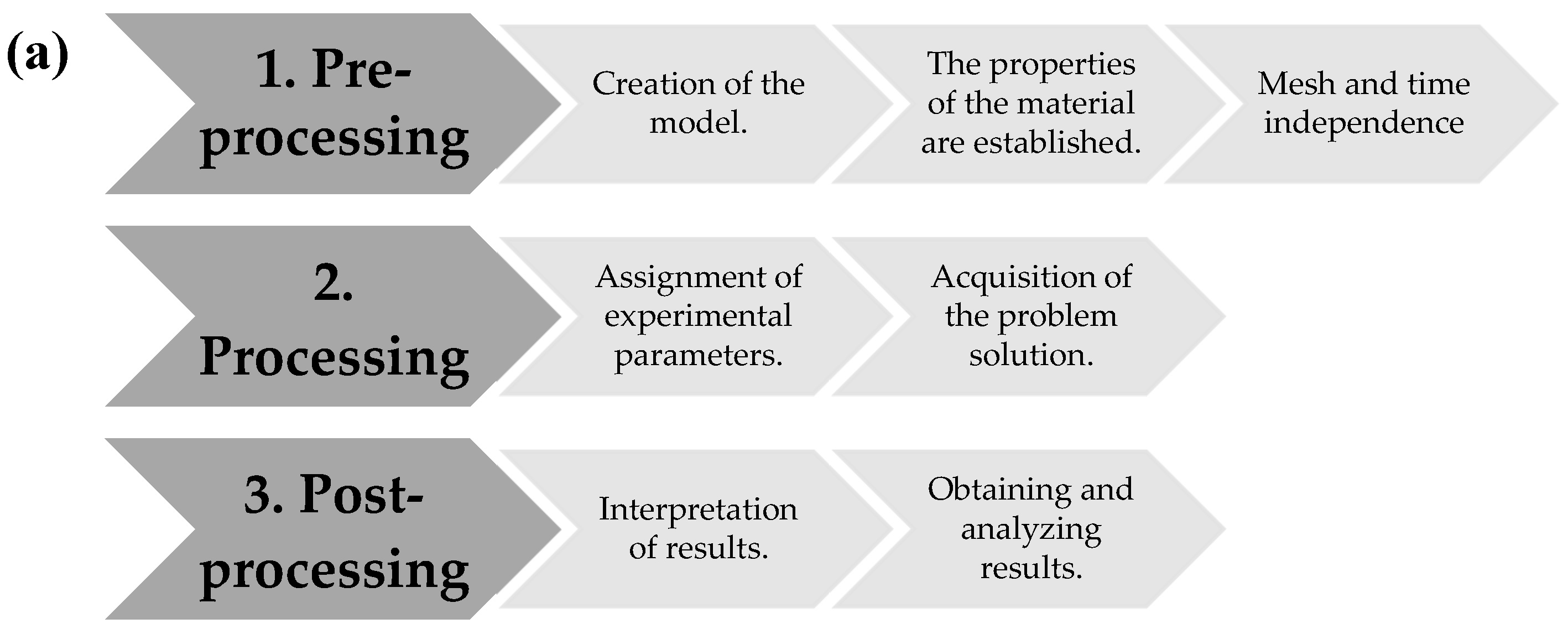
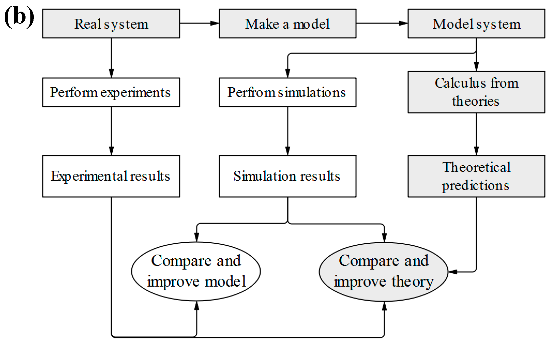
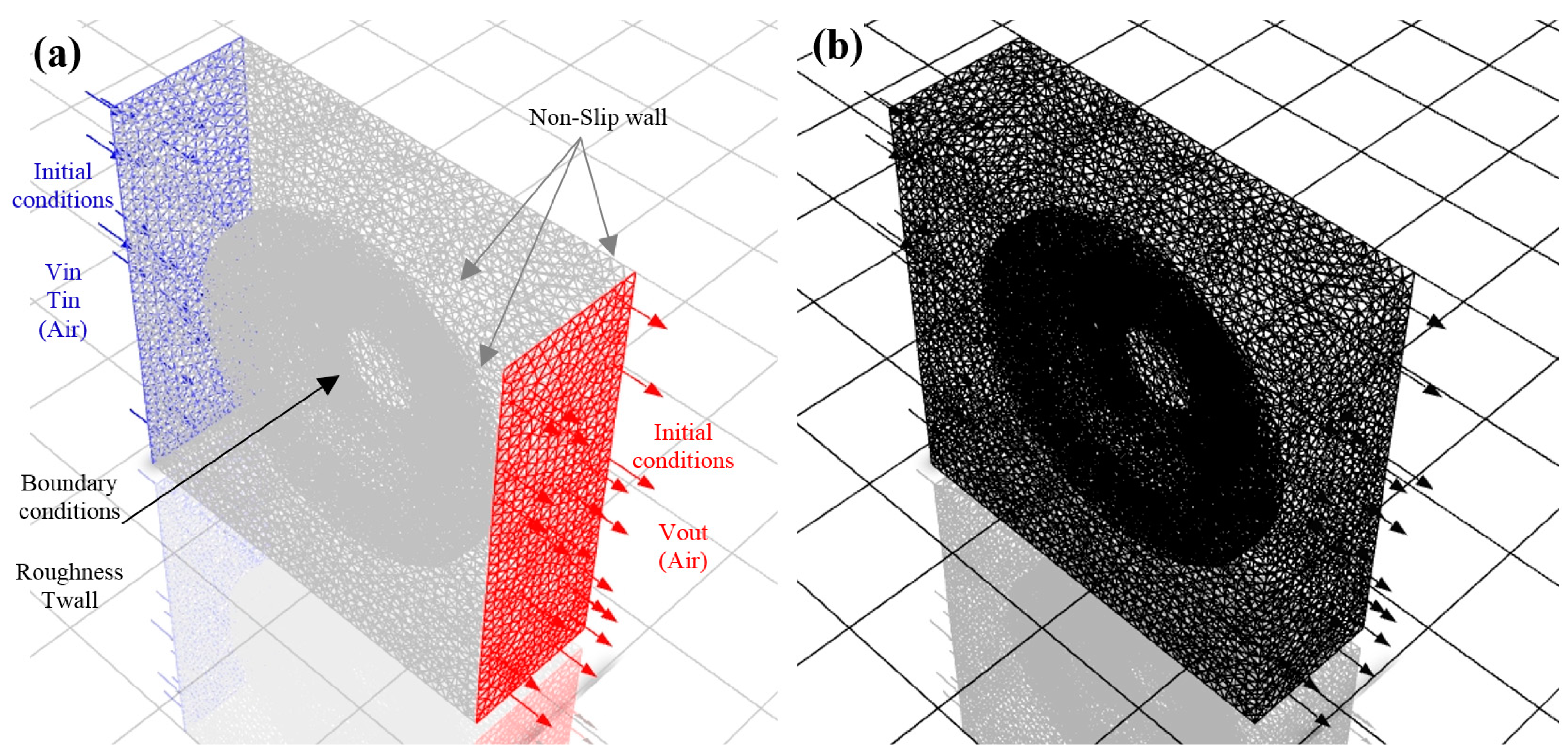
2.4. Computational Fluid Dynamics (CFD Simulation)

The numerical simulations developed in this study consider the interaction of the fluid-disc brake without its rotation, where the air is the same speed as the automobile, and thus perform the CFD analysis in a transient state. Initially, the Solidworks 2017 student version software was used, which is a CAD-3D design program, to design 2D parts and 3D assemblies. Likewise, it provides a complete group of tools to produce, reproduce, and publish, as well as manage data, projects, and processes, and increase innovation and the efficiency of engineering resources. All these solutions work together to allow institutions to design better products quickly and productively [41].
Subsequently, the CAD-3D designs of the disc brakes were imported into ANSYS/2020-R2 student version software, which was used for the design, analysis, and simulation of parts through FEA and CFD, performing the stages of execution of the simulations shown in Figure 3. In order to solve the mechanical problems, this graphic interface processor includes, for the development of this research, heat and mass transfer analysis [42].
Ansys Flow Simulation solves the Navier–Stokes equations, which are formulations of the laws of conservation of mass, momentum, and energy and are presented below [43,44]. Three-dimensional models of the disc brake and fluid domain (air) were constructed to develop the CFD cooling analysis. FLUENT was used to solve the equations of continuity, momentum, and energy for pressure and velocity coupling. The turbulent model was solved based on the Reynolds-Averaged Navier–Stokes equations (RANS) approach with an achievable k-ε model, which is a variant of the standard k-ε model. The continuity and moment expressions are described according to energy Equations (12) and (13), used to calculate the high-velocity incompressible flows and ripple flow:
ρ t + ( ρ u i ) x i = 0
t ( ρ u i ) + x j ( ρ u i u j ) = p x i + ρ g + x j [ μ ( u i x j + u j x i 2 3 δ ij u l x l ) ] + x j ( ρ u i u j ¯ )
In this case, the density is a function of the temperature according to the ideal gas law. The realizable k-ε turbulent model is given by the transport expressions for the turbulent kinetic energy (k) and the turbulent dissipation rate (ε), respectively by Equations (14) and (15):
t ( ρ k ) + x j ( ρ ku j ) = p x j [ ( μ + μ t σ k ) k x j ] + G k + G b ρ ε Y M + S k
t ( ρ ε ) + x j ( ρ ε u j ) = p x j [ ( μ + μ t σ ε ) ε x j ] + ρ C 1 S ε ρ C 2 ε 2 k + ν ε + C 1 ε ε k C 3 ε G b + S ε                
where:
C 1 = max [ 0.43 , η η + 5 ] ,   η = S k ε ,   S = 2 S ij S ij  
Additional details of the realizable k-ε model and parameters using the above equations can be found in [45]. To obtain the temperature field, the energy equation was solved as presented in Equation (17):
t ( ρ C p T ) + x i ( ρ u i h ) = x j [ λ T x j ]
where λ is the thermal conductivity, which for the fluid domain becomes λ + λt, and λt is the turbulent thermal conductivity. Likewise, the temperature distribution in the disc brake was obtained by solving Equations (12)–(17).
The boundary conditions were established as follows according to the analytical model. Specified disc surface temperature ST × T = T*. Heat flux entering the disk SQ: [QT][n] = −Q*. Specified convection on the surface of the disc SC: [QT][n] = h (TS − TF). Where ST is the surface temperature, T is the temperature, T* is the specific surface temperature, SQ is the surface heat, Q* is the surface-specific heat, SC is the disc surface convection, h is the convection coefficient of the air, TS is the surface temperature, and TF is the fluid temperature.
The initial conditions for the simulations are the speed (80 km/h), the air temperature (33 °C and T(x,y,z) = 100 K), the disc brake surface temperature, and a disc without rotation. Surface temperatures are shown in Table 4, and considerations in Section 3.2.

2.5. Grid Type

For the transient-state simulations, a tetrahedral mesh was selected in the computational domain of the fluid (Figure 4). This mesh has a more significant number of elements compared to the polyhedral type [46]. The grid was adjusted to the unstructured solid through the construction of nodes distributed in an irregular way. In addition, with this type of mesh, it is much easier to perform complex structures, achieving more efficiency in computational time when performing the respective numerical analyzes on the disc brakes.

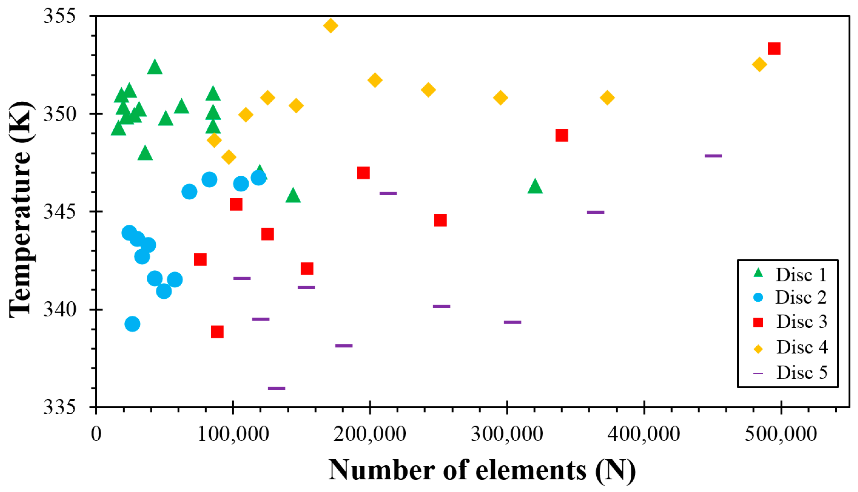
2.5.1. Mesh Independence Study

In Figure 5 the mesh independence study is presented. The fluid exit temperature of the computational domain was evaluated for 500,000 elements. It was observed that in order to obtain an error of less than 5%, the mesh must have from 450,000 to 500,000 elements. Moreover, the air outlet temperature and velocity are not influenced by the number of elements in the mesh for a number of 450,000 to 500,000 elements.

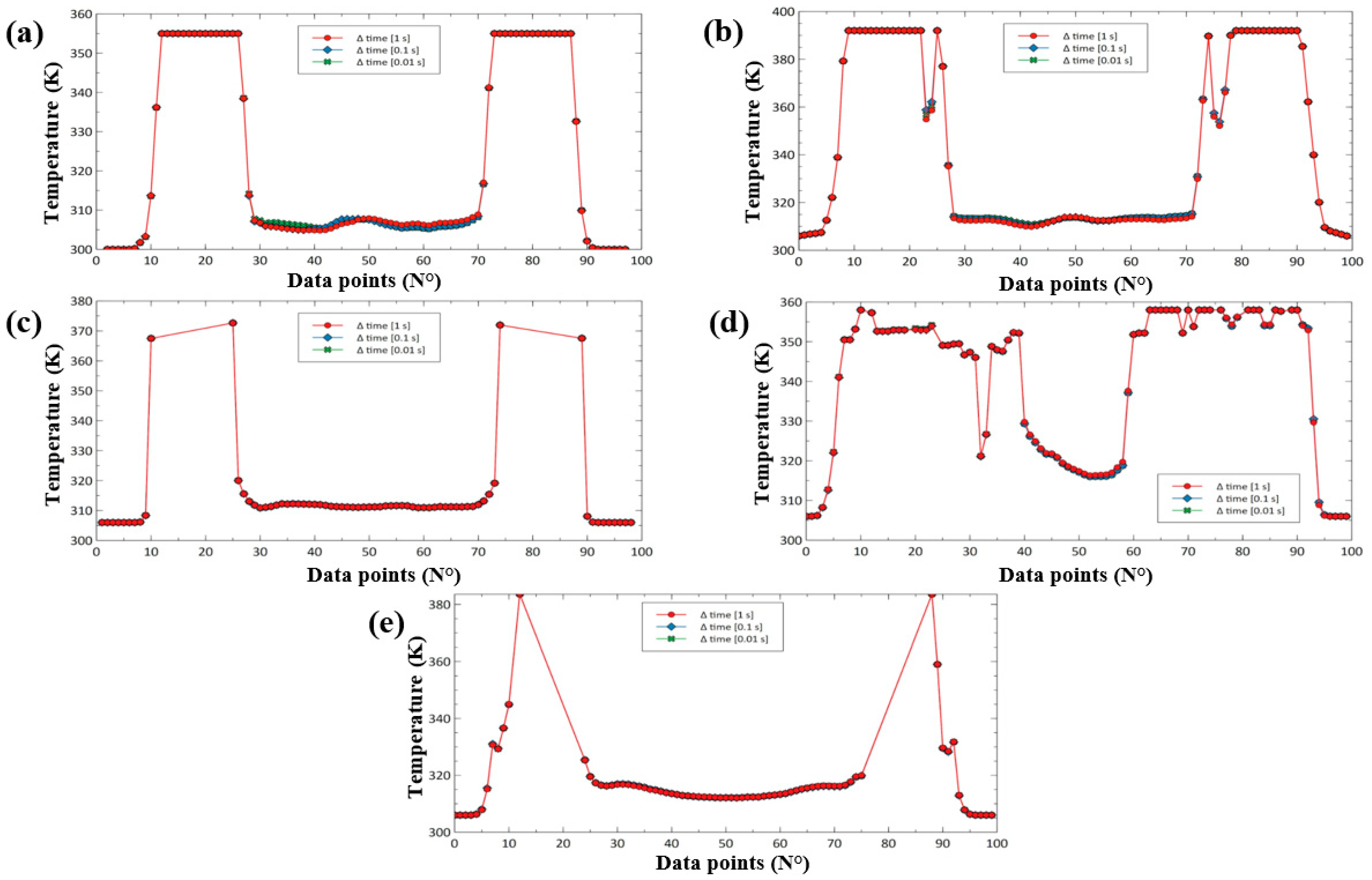
2.5.2. Independence of Time

In Figure 6 the temperature behavior as a function of the data points and the time behavior for each disc brake is observed, where the different sections of the discs were measured. On the other hand, it was confirmed that the temperature does not change as a function of time, ranging from 1, 0.1, and 0.01 s. Considering the results obtained from the time step not varies using whatever time step (1, 0.1, and 0.01 s, presented the same behaviors in the plot), for this reason, 0.1 s was selected to perform the simulations of the thermal behavior and fluid dynamic behavior. Notice that the simulation was configured under the following parameters: 0.1 s of the time step, 1200 time step number, and 500 maximum interactions by time step. With these parameters, the total time of simulation was 120 s. With time independence, the aim is to ensure that the results are reliable for the different time intervals used depending on the number of elements.

3. Results and Discussions

For the development of the numerical model, heat transfer equations were used, considering parameters such as braking time, vehicle speed, geometries and dimensions of the brake components, the disc brake rotor materials, and the distribution of pad and contact pressure. The results show a heat split at the contact surface of two sliding components due to thermal resistance. This happens because of the accumulation of wear particles between the contact surfaces. This phenomenon prevents the discs from absorbing more heat and makes the brake lining hot [47].

3.1. Mathematical Results of Heat Transfer

Each of the proposed equations were developed considering the theories of heat transfer. Table 3 summarizes the calculation of the total energy in the disc brake, the heat generated during braking, and the rate of overall heat loss in the disc and the ducts using Equations (1)–(11). For the value of QTotal in disc, the rate of heat loss in the bell, the periphery, and the rotating effect of each disc brake were considered. The same considerations were taken for the convection coefficient. Notice that the disc brake geometry affects all those variables, but it affected E in a greater way. It means that a big disc brake provides better performance during the braking process and thus improves heat dissipation, but it will depend on the blade type. These results agree with those presented by [38,48], which concluded that the type of the pad and frequency of braking also affects the braking process during wear with the disc. In addition, convective values are between 0 and 100 W/m2 × K [49]. It is worth noting that the behavior and Q values of the disc brake ducts have not been reported. In addition, the total Q in the ducts is less than the total Q in a disc brake. Thus, there is a correspondence with the theories related to heat transfer.
According to Lakkam et al. [40], a surface temperature of at least 300 °C on the disc brake increases with the pressure applied during the braking process at a speed of 80 Km/h, and changes with the operational conditions of the automobile such as weight, speed, tire and roadway conditions.
However, the heat generated during the braking process is approximately 5.4% higher because the braking time in this research is shorter (around ~2.38 s for all discs), and the energy dissipated in the disc is smaller (Table 3). On the other hand, the rate of heat loss inside the ventilation ducts had an increase of 9%, compared to that calculated by García-León [19]. This happens because the characteristics of the ventilation ducts are similar and the assumed and ambient temperature is 13 °C higher, affecting the values of the air properties and therefore the Reynolds number, which consequently affects the calculation of the convective coefficient, which depends on the car capacity and the geometry of the disc brake. The angular speed is higher (between 57 to 102 rad/s) on the disc brake which depends on the tire characteristic and designation (width, radius and others), which aids the process of heat dissipation to the environment by natural convection [6]. Similar results to Echavez-Díaz and Quintero-Orozco were found [34].
Table 4 summarizes the temperature results on the surface of the discs using Equations (4) and (5). Note that the temperature differential between the disc brake and the ambient temperature must be known. This was taken as 33 °C for an arid region (Aguachica, Colombia), where the mathematical calculations and numerical simulations were carried out.
The temperature difference is 1.1% less and 34% greater than that calculated by [19,34]. It occurs because the mass and total energy in the disc are similar. This indicates that a vehicle with a mass of ~1650 Kg and speed of 80 km/h, circulating in an environment of 33 °C, with a friction surface between the disc and the pad, generates a disc brake temperature of approximately 84.96 to 119 °C to stop the vehicle, obtaining results similar to those found by Topouris, et al. [17] and Lakkam et al. [18].

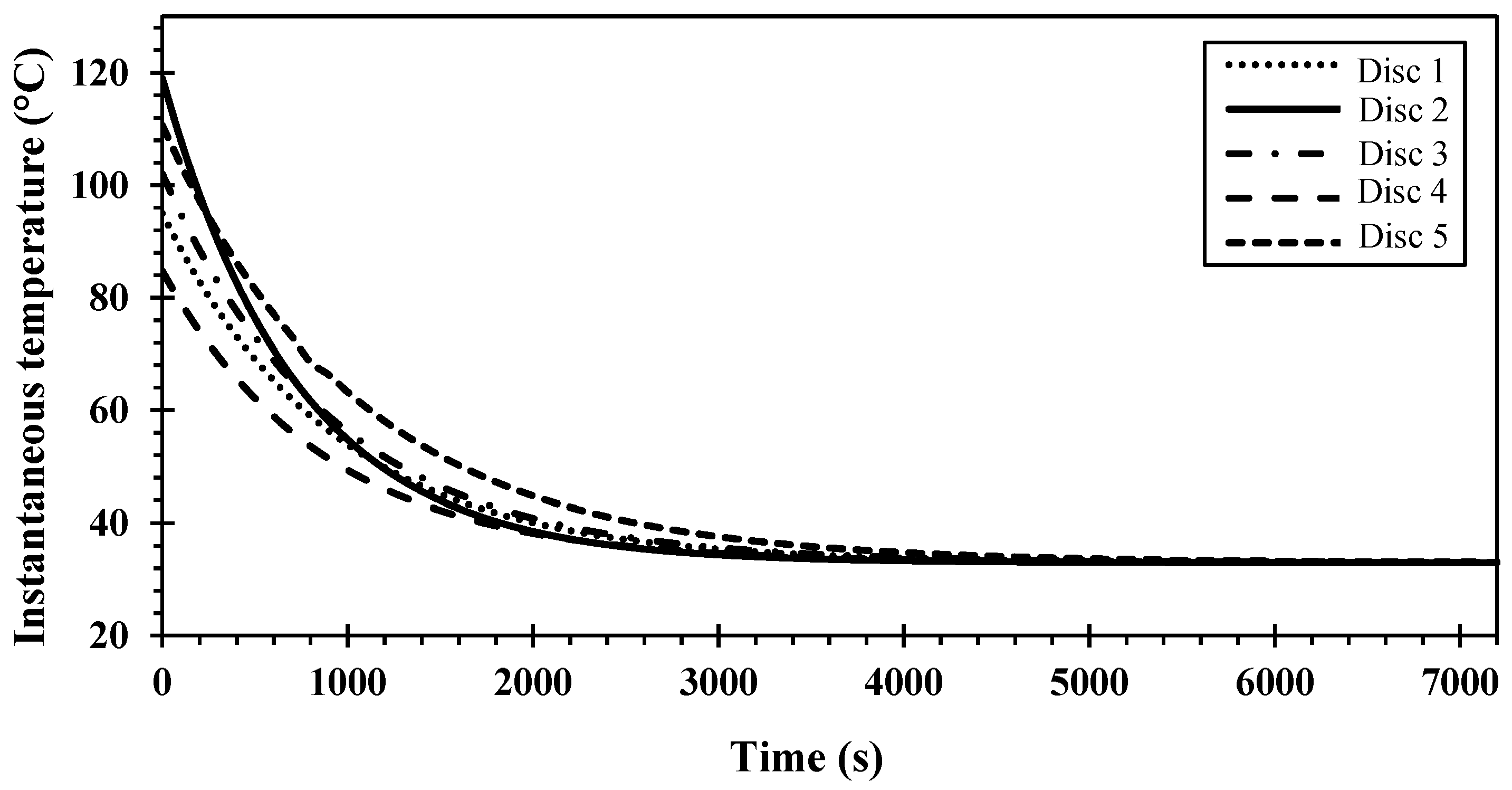
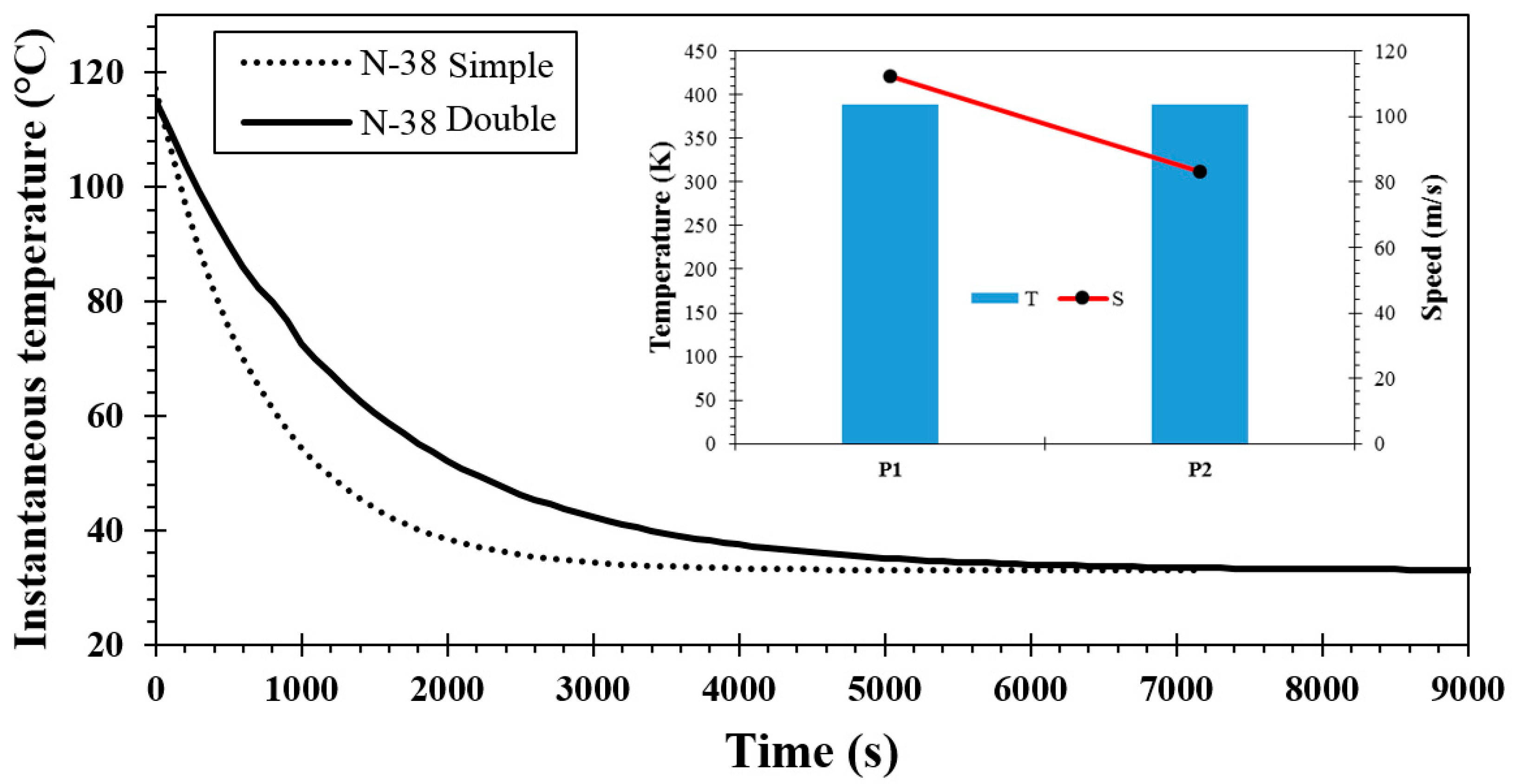
3.2. Newton’s Law of Cooling Results

Figure 7 shows the behavior of the disc brakes under the calculations performed using Equation (4) for 100 s intervals. Natural convection during heat dissipation from the braking track is the sum of the convection in the bell and at the periphery of the disc. These results are based on the speed limit allowed in Colombia and the average ambient temperature in the city of Aguachica, Colombia.
The disc brake will reach an ambient temperature of 33 °C in around 30 min after being subjected to the different temperatures on the surface of the braking track during the friction process between the disc and the pad. It will happen as long as the cooling process occurs by natural convection, that is, the air in the environment must have a speed equal to zero [1,24,50]. From Figure 6, Disc 2 reaches the environmental temperature at 6700 s, while the other discs at approximately ~7200 s.
The speed of the vehicle influences the kinetic energy that is generated during the movement. It does not affect it linearly but increases its value exponentially. This means that a vehicle of the same weight but twice the speed of another vehicle does not require twice the braking force to stop the vehicle, but four times more. Therefore, the stopping distance will be longer, as long as the vehicle rides on a flat road [51]. On the other hand, the material of the brake pad influences the thermodynamic properties of the disc brake, and thus the increase in temperature. However, the material of the disc brake, the geometry, and the configuration of the blades are relevant factors in the heat dissipation to the environment, so they affect the useful life of the brake pad components of the braking system [39].

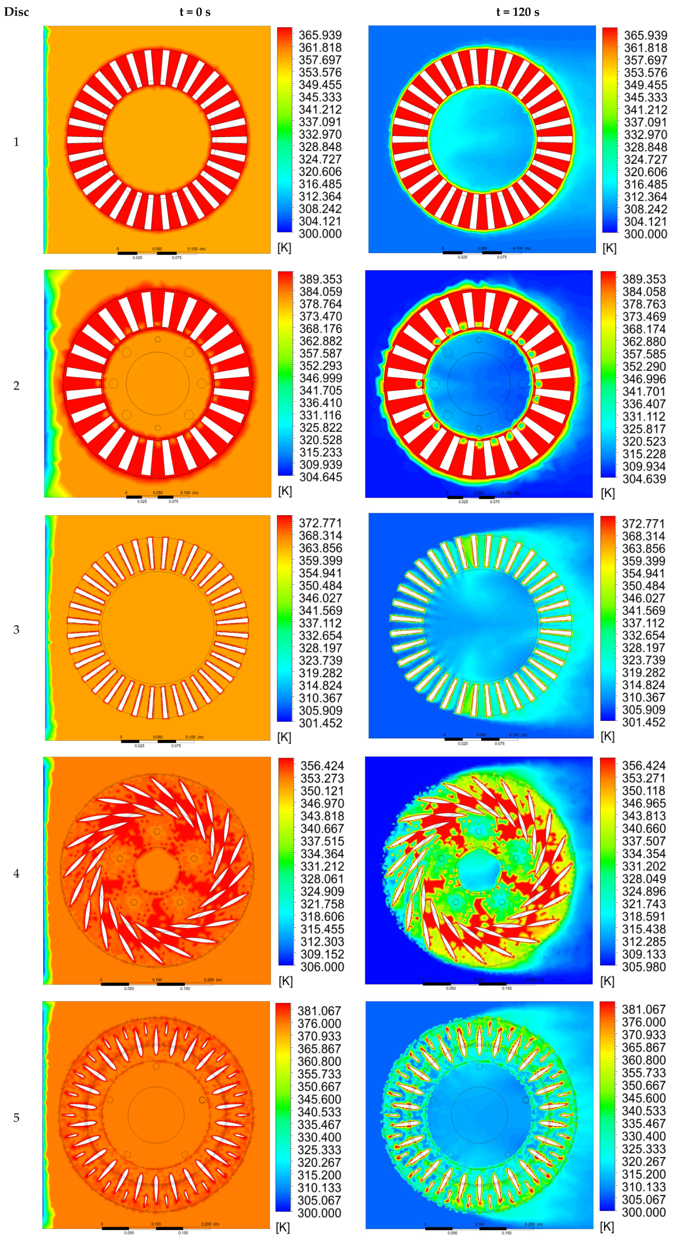
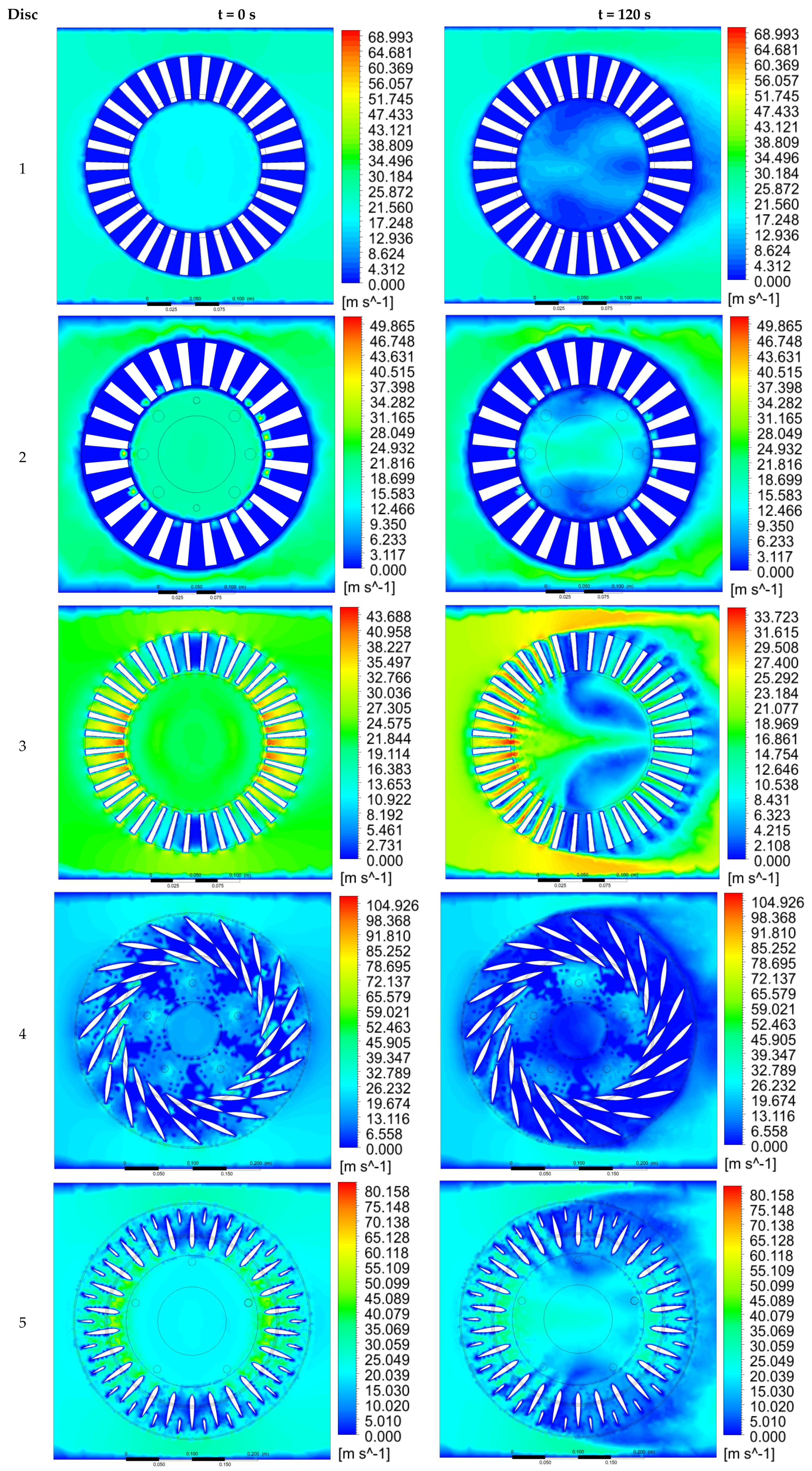
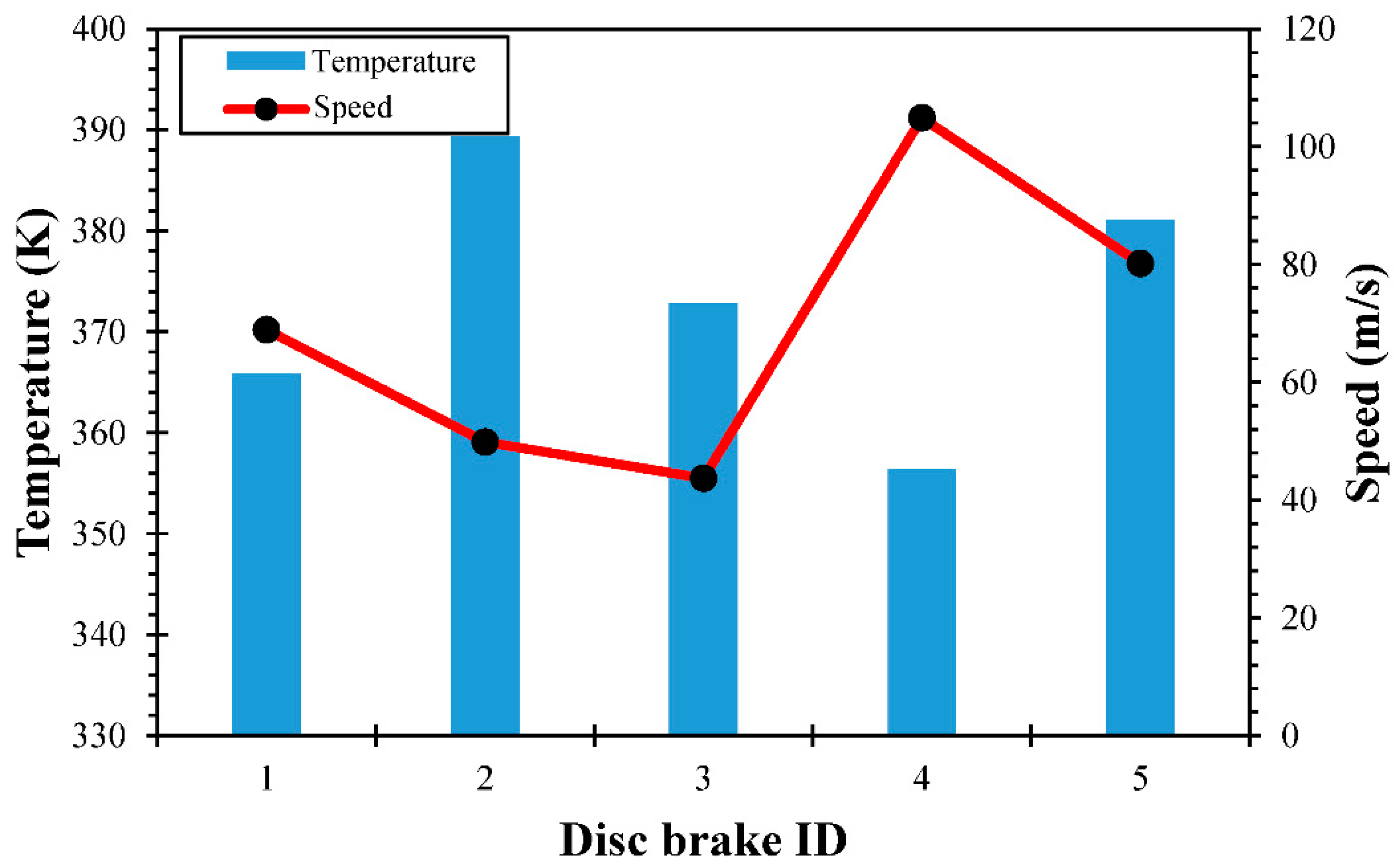
3.3. CFD Results of Temperature and Fluid Speed Behavior

CFD analyses show the temperature and fluid behavior through colored bars. The temperature dissipated during the braking process and the speed of the air inside the ventilation ducts are presented in a color scale where red represents the highest trend, light green refers to an intermediate value, and dark blue represents the lowest trend for both variables. The values of grind and time independence are similar to those reported by [29].
In this way, Figure 8 and Figure 9 show the heat flow behavior and the airspeed of the five-disc brakes, respectively, using the student version of ANSYS FEA software, which was measured in two time intervals of 0 and 120 s [13]. The mechanical, physical, and thermal properties of lamellar graphite nodular gray cast iron are presented in Table 1.
In the developed simulation, a thermal and fluid dynamic analysis was carried out. In the time intervals used it can be observed that the thermal behavior of Disc 4 is the best as the surface temperature reached 69.1 °C. This value decreased after activating the brake system for a time of 120 s. This can be verified by observing the airspeed of ~6.55 m/s in the fluid dynamic analysis (Figure 9). Therefore, it can be seen that this is the highest compared to the other speeds of the other discs, checking with the heat dissipation values [16].
From Table 4 and Figure 8, the analytically calculated temperature and that obtained by ANSYS FEA software student version are presented. The temperatures in a time of 0 s are 95, 119, 102, 84.69, and 110.6 °C, while the ones obtained in the simulation were 92.9, 101.4, 91.5, 80, and 108 °C. The percentage differences between the temperatures mathematically calculated and the ones obtained by numerical simulation are 2.2, 14.8, 10.3, 5.5, and 2.4%, respectively for each disc brake. This margin of error is acceptable because it is less than 15%. It can be observed that Disc 4 reaches a temperature of 69.1 °C after 120 s of operating the brake system, while the other discs reach a temperature of 76.5, 79.6, 77.5, and 108.1 °C, which allows us to deduce that Disc 4 is the optimal disc brake.
In the same way, it was determined by simulation that the airspeed values inside the ventilation ducts, which are presented in Figure 8, are 4.35, 3.11, 1.91, 6.55, and 5.02 m/s. This confirms that the highest airspeed inside the ventilation ducts occurs in Disc 4, which causes the temperature to decrease more quickly (see Figure 7).
Considering the heat transfer values summarized in Table 3, it was evident that the rate of heat dissipated by Disc 2 is higher compared to that of the other discs brakes. It can be explained as Disc 2 reaches a higher surface temperature before and after applying the brake system, which increases the rate of heat evacuated. On the other hand, the aforementioned results were compared with those calculated analytically by García-León [19], in which heat loss values of 405.66, 644.24, and 595.71 W are presented in Disc 1, Disc 2, and Disc 3, respectively. The results of Disc 4 were compared with the results of Echavez-Díaz and Quintero-Orozco [34], where the surface temperature was 60.5 °C and the evacuated heat rate was 337.26 W in Disc 4. In this investigation, the surface temperature is 84.69 °C and the evacuated heat rate is 919.95 W, which represents a difference of 28.5 and 62%, respectively. The contrast in the results resides in the different values for the surrounding temperature, being 20 °C in the Echavez-Díaz and Quintero-Orozco research and 33 °C in this one. Figure 10 summarizes the results obtained by CFD for temperature and airspeed. Notice that this figure was obtained with the temperature generated by the disc brake which was calculated mathematically under ideal conditions, and the relationship with the airspeed for the different disc brakes studied aids the heat dissipation.
Finally, for a geometric configuration with a more significant number of profiles, airflow blocking can occur at low rotation speeds. This is mainly due to the reduction of the effective surface of the disc brake. That is, the number of profiles directly affects air circulation [25].

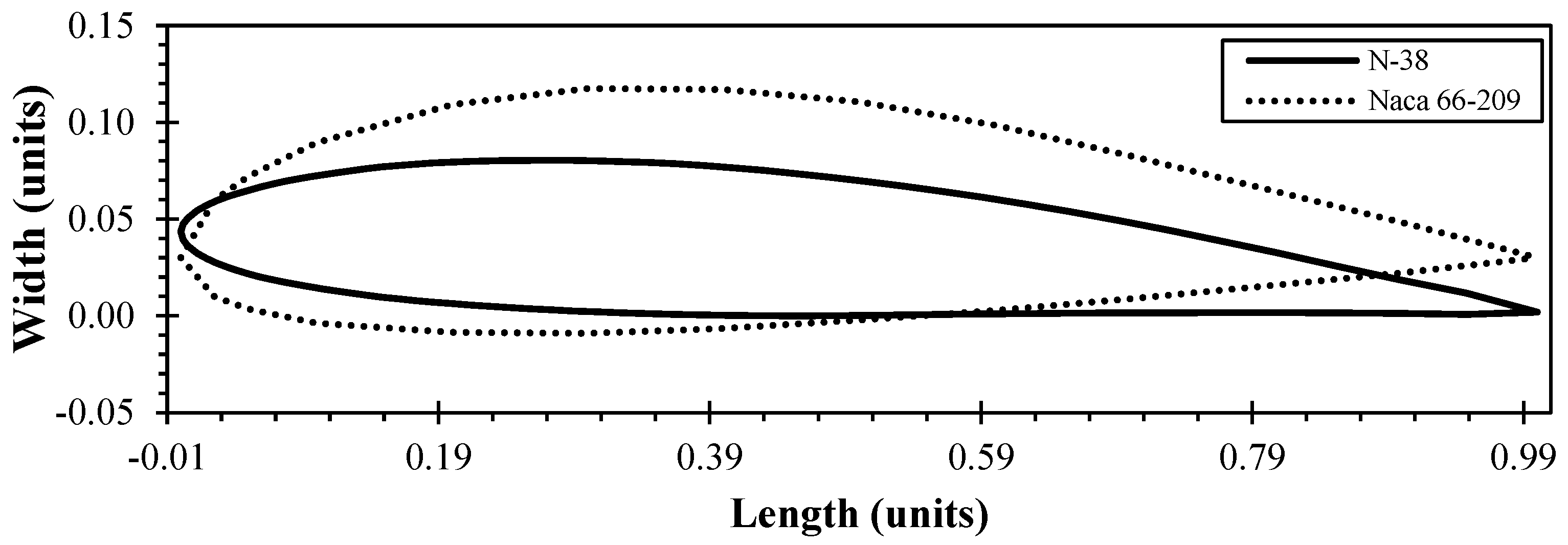
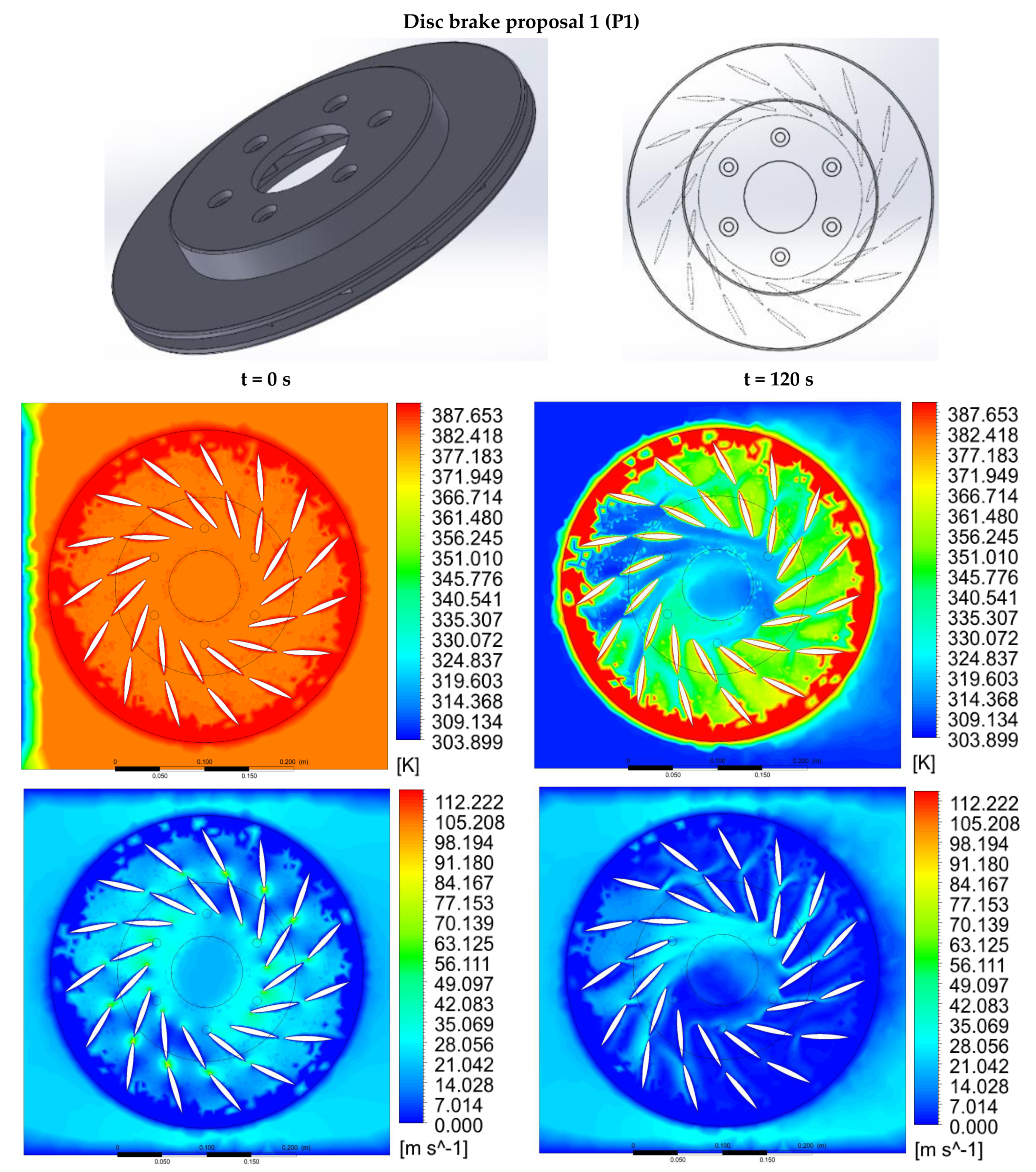
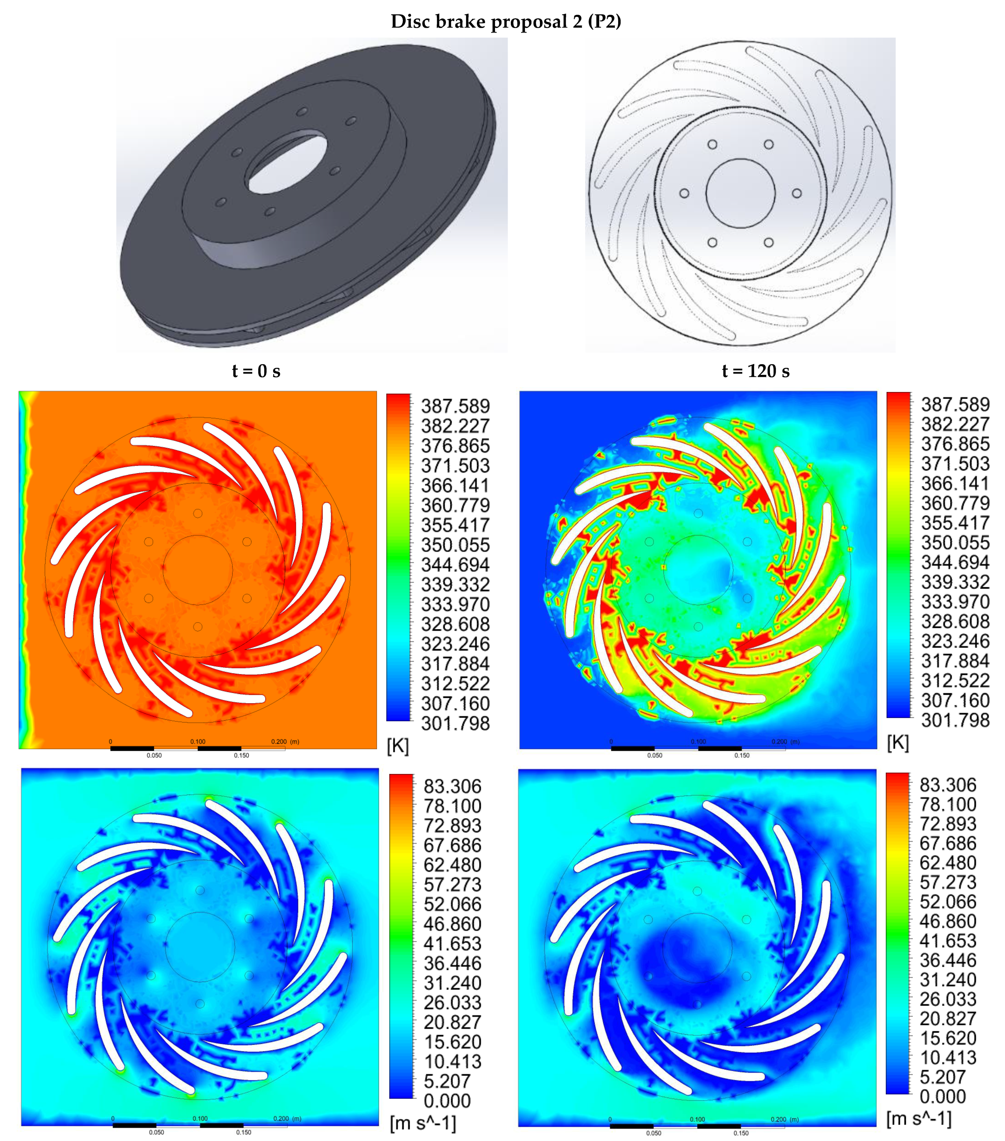
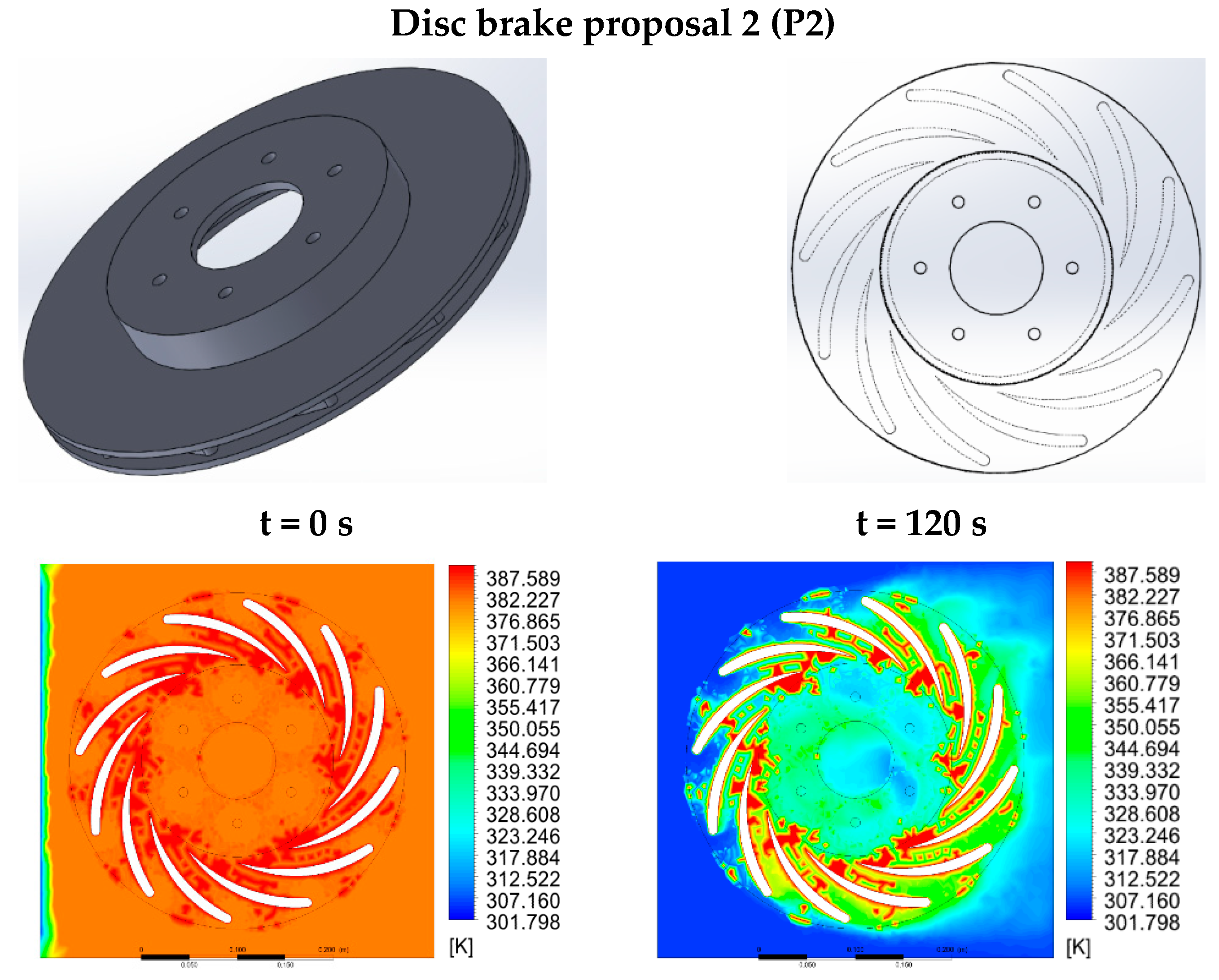
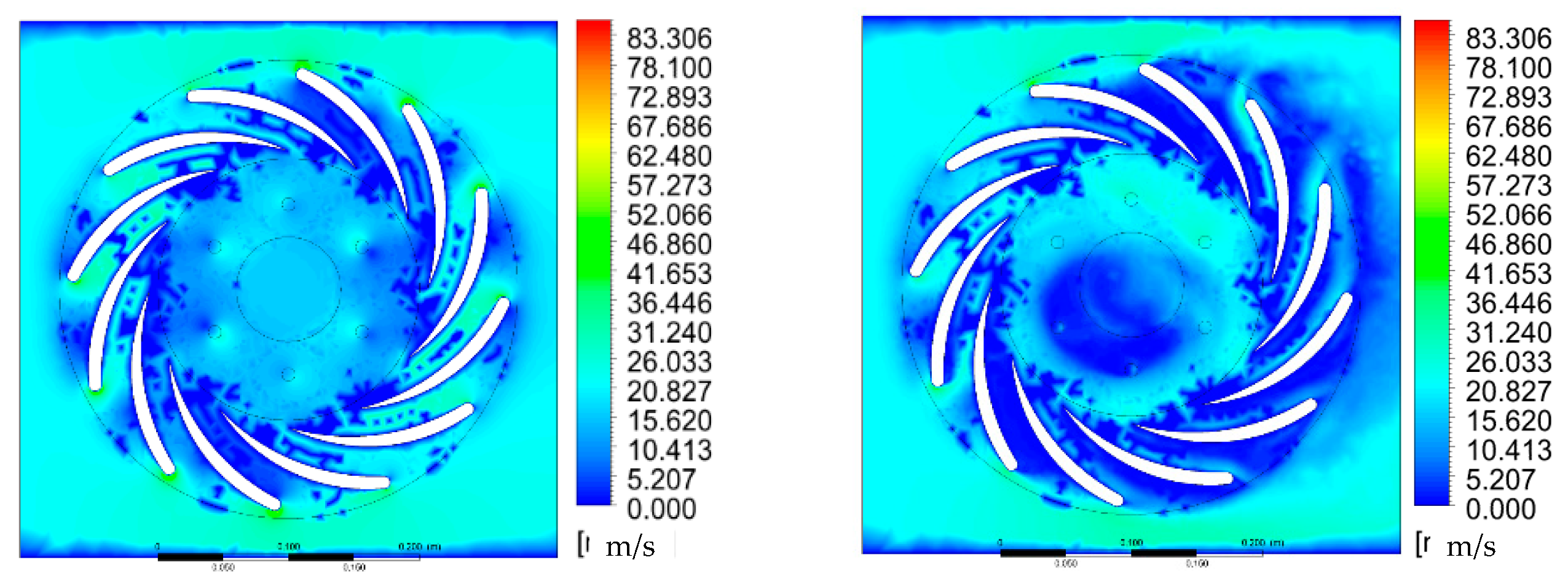
3.4. Proposal for a New Disc Brake Geometry

Two new geometries that improve heat dissipation during the braking process are proposed after having analyzed the previous results. The first one is an automotive disc brake with N-38 type ventilation blades and a single wing and the second has a double wing. These configurations have a more aerodynamic profile compared to the automotive disc brake with the NACA 66–209 type ventilation blades, which makes the airflow inside the ventilation blades circulate with better efficiency, and the rate of heat evacuated higher, thus increasing the efficiency of the disc brake. According to the authors of [22], an increase in the number of blades in the disc brake geometry design does not promote the block effect at low speeds and also provides better performance for heat dissipation. Table 5 presents the most relevant parameters and dimensions of the proposed brake discs.
Figure 11 shows the geometry of the ventilation blades which, depending on the configuration of the disc brake, achieves the highest heat dissipation.
The simulation was carried out in the ANSYS software, having established two possible optimal disc brake configurations, obtaining the results shown in Figure 12 and Figure 13.
In the simulations presented in Figure 12 and Figure 13, a thermal and fluid dynamic analysis was carried out, which was carried out in two time intervals of 0 and 120 s, where it is observed that the disc of the disc brake proposal 2 reaches a lower temperature of ~66.3 °C. In comparison, disc brake proposal 1 reaches a higher temperature, which is 114.7 °C. Likewise, it was possible to observe that the airspeed inside the ventilation blades in disc brake proposal 1 reaches values of ~7.014 m/s. In contrast, disc brake proposal 2 reaches a higher airspeed of ~10.41 m/s, which confirms what has been said above regarding the dissipated temperature because the higher airspeed inside the ventilation blades leads to a significantly lower surface temperature. Likewise, these two new geometries were compared with the previously analyzed geometries, for which it was possible to deduce that disc brake proposal 2 improved by approximately 23.8% on average for the dissipated temperature. This is because the ventilation blades of the two disc proposals have a more aerodynamic tendency, which makes the air circulate more quickly inside them, and therefore, the dissipated heat transfer rate is higher.
On the other hand, the behavior of Newton’s law of cooling for the two brake proposals is shown in Figure 14. It is evident how the disc brake proposal 2 (N-38 simple) dissipates heat faster by natural convection. This process is generated in less than 100 min, being much lower compared to the five-disc brakes studied in this research (Figure 8 and Figure 9).
The rotation of the disc brake is directly regulated by the blade angle, and the method that defines the displacement of the rotor angle at a given moment is different. In this way, some considerations are important to recall: the contact pressure leads to non-uniform temperature when the pressure applied is not constant. The high local temperature results in greater thermal expansion and leads to an increase in the local pressure, generating more friction on the braking track. The convection in the disc impacts the temperature field during the cooling process, and thus the temperature is reduced with the aid of the cooling channels [26].
According to the authors of [6], the type of geometry of the disc brake blades improves the total heat transfer up to 20%, more with teardrop pillars, depending on the rotor speed. In this way, the new geometry proposed in this work increases the total heat transfer by around 24% due to the air flux speed generated on the N-38 type blades, promoting the mass flow rate in the quick heat dissipation. In addition, the internal convection increases linearly with speed, which increases much more quickly compared with the external convection [53]. Notice that, due to the discontinuity of the profile design in the disc brake proposal 1 (double blade), the flow has the largest contact on the disc surface, which is reduced due to the turbulence of the flow generated between the blades. In contrast, in the disc brake proposal 2, the profile design is continuous to the center of the disc, which promotes the flow along the duct disc related to the lines of continuity of the flow. Compared with the results obtained in Figure 8 and Figure 9, for the thermal and fluid-dynamic behavior of the common disc brakes, it is evident that a delay in the heat dissipation on the behavior of the disc brakes with these parameters reduces the performance of the disc brake.

4. Conclusions

The results obtained for the contact surface temperatures between the disc and the pad demonstrate a distribution of heat between two components in sliding contact due to the high-temperature gradients and the operating conditions that affect the ventilation of the disc, and; therefore, heat dissipation to the environment.
It was evidenced through the calculations that the increase in the temperature in the braking track is mainly influenced by the pressure exerted during braking, as well as the time in which this action is executed. On the other hand, the wear of the brake pad is influenced by the braking actuation time, and thus by the mechanical properties of the brake pad and the disc brake materials.
With the different mathematical calculations and theories of heat transfer, it was possible to determine the surface temperature in the braking track and the rate of heat loss for each disc brake. The surface temperature values determined in a time equal to zero are 95, 119, 102, 84.69, and 110.6 °C. Likewise, the values of the rate of heat evacuated in a time of zero are 745.11, 1463.64, 1320.56, 919.95, and 1399.22 W. These results allowed concluding that the higher the surface temperature, the higher the rate of heat transfer evacuated during the braking process. Thus, using the Solidworks design software, the different geometries of the discs were developed and later imported into the student version of the ANSYS simulation software to carry out the respective simulations of airspeed and surface temperature on the braking tracks.
The results of the simulations were analyzed and compared with the mathematical calculations previously made. It was possible to observe the surface temperatures on the braking track after 120 s, with values of 76.6, 79.3, 77.5, 69.1, and 108.1 °C, respectively, for each disc brake. It was observed that Disk 4 reaches the lowest temperature compared to the other geometries. This occurs because the area of the braking track is smaller, as a result, the friction surface is also smaller, which makes the temperature lower. Likewise, in the simulation, the airspeed inside the ventilation ducts was determined, where values of 4.31, 3.11, 1.91, 6.55, and 5.02 m/s were found. The speed inside the ventilation ducts in Disk 4 is higher.
Finally, two proposals for new geometries were made. It was observed that in disk proposal 2, with a simple type N-38 ventilation blade, an improvement in temperature dissipation was achieved by approximately 23.8%, compared to the previous geometries analyzed. This is due to the aerodynamics of the ventilation blade, which makes the air circulate more quickly, and therefore, the generated temperature is evacuated faster.

Author Contributions

R.A.G.-L.: supervision, project administration, sources, conceptualization, methodology, formal analysis, writing—original draft preparation, writing—review and editing. N.A.-G. and J.A.G.-C.: formal analysis, funding acquisition, sources, visualization, validation, other contribution. All authors have read and agreed to the published version of the manuscript.

Funding

This research received no external funding.

Institutional Review Board Statement

Not applicable.

Informed Consent Statement

Not applicable.

Data Availability Statement

Not applicable.

Acknowledgments

This work was supported by the Universidad Francisco de Paula Santander Ocaña, Colombia.

Conflicts of Interest

The authors declare no conflict of interest.

Nomenclature

D External Disc brake outer diameter. (m).
D Inner Disc brake inner diameter. (m).
D Bell Disc brake bell diameter. (m).
E Disc Disc thickness. (m).
E Bell Bell thickness. (m).
E Total   in   disc Total energy in the disc brake. (J).
E Each   disc Energy in each disc brake. (J).
N Blades Number   of   blades .   ( N )
Q Heat generated during braking on the disc. (W/m2).
Q Total   in   disc Total heat loss rate in the disc brake. (W).
Q Bell Rate of total heat loss in the brake disc bell. (W).
Q Peripheral Total heat loss rate at the periphery of the disc brake. (W).
Q Rotary Total heat loss rate by rotating effect of the disc brake. (W).
ΔTTemperature differential between the disc brake and the environment. (°C).
E Disc   brake Disc brake energy. (J).
m D Disc brake mass. (Kg).
CPSpecific heat of the material. (J/Kg × °C).
TiInstantaneous temperature at all times. (°C).
T∞Ambient temperature. (33 °C).
AHeat transfer area. (m2).
UCoefficient of surface thermal transmission of the material. (J/s × m2 × °C).
gAcceleration of gravity. (9.81 m/s2).
tNewton cooling time. (s).
NuNusselt number. (Dimensionless).
KThermal conductivity. (w/m× °C).
DDisc brake diameter. (m).
υFluid kinematic viscosity. (m2/s).
ωangular speed. (Rad/s).
Re g Reynolds number for rotary convection. (Dimensionless).
T p Disc periphery temperature. (m).

References

  1. García-León, R.A.; Flórez-Solano, E.; Acevedo-Peñaloza, C. Análisis Termodinámico en Frenos de Disco; ECOE Ediciones: Bogota, Colombia, 2018. [Google Scholar]
  2. García-León, R.A.; Flórez-Solano, E.; Suárez-Quiñones, Á. Brake Discs: A Technological Review From Its Analysis and Assessment. Inf. Téc. 2019, 83, 217–234. [Google Scholar] [CrossRef]
  3. Iteco Ingenieros. El triángulo de la Seguridad en tu vehículo. Available online: https://www.itecoingenieros.com/el-triangulo-de-la-seguridad-en-tu-vehiculo/ (accessed on 10 October 2020).
  4. Sibuscascoche.com, Qué es el triángulo de seguridad de nuestro coche. Available online: https://www.sibuscascoche.com/noticias/2019/seguridad-vial-triangulos-reflectantes-help-flash/#:~:text=Fue%20ideado%20con%20la%20intenci%C3%B3n,contabilizados%20m%C3%A1s%20atropellos%20y%20colisiones (accessed on 10 October 2020).
  5. Lorenzo, S.S. Propuesta de Diseño Para Disco de Freno Ventilado; Universidad de Valladolid: Valladolid, Spain, 2018. [Google Scholar]
  6. Wallis, L.; Leonardi, E.; Milton, B.; Joseph, P. Air flow and heat transfer in ventilated disc brake rotors with diamond and tear-drop pillars. Numer. Heat Transf. Part A Appl. 2002, 41, 643–655. [Google Scholar] [CrossRef]
  7. McPhee, A.D.; Johnson, D.A. Experimental heat transfer and flow analysis of a vented brake rotor. Int. J. Therm. Sci. 2008, 47, 458–467. [Google Scholar] [CrossRef]
  8. García-León, R.A.; Rojas, E.P. Analysis of the amount of heat flow between cooling channels in three vented brake discs. Ing. Y Univ. 2017, 21, 71–96. [Google Scholar] [CrossRef] [Green Version]
  9. Atkins, M.; Kienhofer, F.W.; Lu, T.J.; Kim, T. Local Heat Transfer Distributions within a Rotating Pin-Finned Brake Disk. J. Heat Transf. 2020, 142. [Google Scholar] [CrossRef]
  10. Park, S.B.; Lee, K.S.; Lee, D.H. An investigation of local heat transfer characteristics in a ventilated disc brake with helically fluted surfaces. J. Mech. Sci. Technol. 2007, 21, 2178–2187. [Google Scholar] [CrossRef]
  11. Nejat, A.; Aslani, M.; Mirzakhalili, E.; Asl, R.N. Heat Transfer Enhancement in Ventilated Brake Disk Using Double Airfoil Vanes. J. Therm. Sci. Eng. Appl. 2011, 3. [Google Scholar] [CrossRef]
  12. Duzgun, M. Investigation of thermo-structural behaviors of different ventilation applications on brake discs. J. Mech. Sci. Technol. 2012, 26, 235–240. [Google Scholar] [CrossRef]
  13. Lee, B.J.; Chung, J.T.; Jung, Y.; Kim, H.; Lee, S.; Kim, H.Y. Numerical Study on Fluid Flow and Heat Transfer Characteristics of a Ventilated Brake Disc Connected to a Wheel; SAE: Warrendale, PA, USA, 2018. [Google Scholar] [CrossRef]
  14. Belhocine, A.; Afzal, A. FEA Analysis of coupled thermo-mechanical response of grey cast iron material used in brake discs. Rev. Cient. 2019, 3, 280–296. [Google Scholar] [CrossRef]
  15. Belhocine, A.; Bouchetara, M. Investigation of temperature and thermal stress in ventilated disc brake based on 3D thermomechanical coupling model. Ain Shams Eng. J. 2013, 4, 475–483. [Google Scholar] [CrossRef] [Green Version]
  16. Jiang, L.; Jiang, Y.; Yu, L.; Yang, H.; Li, Z.; Ding, Y. Thermo-Mechanical Coupling Analyses for Al Alloy Brake Discs with Al(2)O(3)-SiC((3D))/Al Alloy Composite Wear-Resisting Surface Layer for High-Speed Trains. Materials 2019, 12, 3155. [Google Scholar] [CrossRef] [Green Version]
  17. Topouris, S.; Stamenković, D.; Olphe-Galliard, M.; Popović, V.; Tirovic, M. Heat dissipation from stationary passenger car brake discs. Stroj. Vestn./J. Mech. Eng. 2019, 66, 15–28. [Google Scholar] [CrossRef]
  18. Lakkam, S.; Suwantaroj, K.; Puangcharoenchai, P.; Mongkonlerdmanee, S.; Koetniyom, S. Study of heat transfer on front-and back-vented brake discs. Songklanakarin J. Sci. Technol. 2013, 35, 671–681. [Google Scholar]
  19. García-León, R.A. Evaluación del Comportamiento de los Frenos de Disco de Los Vehículos a Partir del Análisis de la Aceleración del Proceso de Corrosión. Licentiate Thesis, Universidad Francisco de Paula Santander Ocaña, Ocaña, Colombia, 2014. [Google Scholar]
  20. García-León, R.A.; Flórez-Solano, E. Dynamic analysis of three autoventilated disc brakes. Ing. E Investig. 2017, 37. [Google Scholar] [CrossRef] [Green Version]
  21. García-León, R.A.; Flórez-Solano, E.N. Estudio analitico de la transferencia de calor por convección que afectan a los frenos de disco ventilados. Tecnura 2016, 20, 15–30. [Google Scholar] [CrossRef]
  22. García-León, R.A.; López, J.E.R.; Quintero-Orozco, A.; Gutiérrez-Paredes, G.J. Análisis del caudal en un disco de freno automotriz con alabes de ventilación tipo NACA66-209, utilizando velocimetría de imagen de partículas. Inf. Tec. 2019, 83, 10–24. [Google Scholar] [CrossRef]
  23. Rivera-López, J.E.; García-León, R.A.; Quintero-Orozco, A.; Diaz-Torrez, E.J.; Gutiérrez-Paredes, G.J.; Echavez-Diaz, R.; Arévalo-Ruedas, J.H. Thermal and fluid-dynamic analysis of an automotive disc brake with ventilation pillars aerodynamic type. J. Phys. Conf. Ser. 2019, 1386. [Google Scholar] [CrossRef]
  24. García-León, R.A.; Echavez-Díaz, R.; Flórez-Solano, E. Análisis termodinámico de un disco de freno automotriz con pilares de ventilación tipo NACA 66-209. INGE CUC 2018. [Google Scholar] [CrossRef] [Green Version]
  25. García-León, R.A.; Acevedo-Peñaloza, C.; Rodríguez-Castilla, M. Análisis del caudal de aire en un disco de freno automotriz con alabes de ventilación tipo N-38. Sci. Tech. 2019, 24, 385–389. [Google Scholar] [CrossRef]
  26. Hwang, P.; Wu, X.; Jeon, Y. Repeated Brake Temperature Analysis of Ventilated Brake Disc on the Downhill Road; SAE: Warrendale, PA, USA, 2008. [Google Scholar] [CrossRef]
  27. Volchenko, N.; Volchenko, A.; Volchenko, D.; Poliakov, P.; Malyk, V.; Zhuravlev, D.Y.; Vytvytskyi, V.; Krasin, P. Features of the estimation of the intensity of heat exchange in selfventilated disk-shoe brakes of vehicles. East. Eur. J. Enterp. Technol. 2019, 1, 47–53. [Google Scholar] [CrossRef]
  28. SN. Descripción y Eficacia del Sistema de Frenado. Available online: http://kashima.campuseina.com/mod/book/view.php?id=7679 (accessed on 20 December 2020).
  29. Afzal, A.; Mujeebu, M.A. Thermo-Mechanical and Structural Performances of Automobile Disc Brakes: A Review of Numerical and Experimental Studies. Arch. Comput. Methods Eng. 2019, 26, 1489–1513. [Google Scholar] [CrossRef]
  30. Esqueda, M.A.A.; Madrid, M.M.; López, J.A. El Tratamiento de los Hierros Nodulares en el Mejoramiento de los Materiales en la Industria Automotriz; Instituto Mexicano del Transporte: Pedro Escobedo, Mexico, 2000.
  31. Ibhadode, A.O.A.; Dagwa, I.M. Development of asbestos-free friction lining material from palm kernel shell. J. Braz. Soc. Mech. Sci. Eng. 2008, 30, 166–173. [Google Scholar] [CrossRef] [Green Version]
  32. García-León, R.A.; Flórez-Solano, E.; Rodríguez-Castilla, M.M. Thermo-mechanical assessment in three auto-ventilated disc brake by implementing finite elements. J. Phys. Conf. Ser. 2019, 11, 1129. [Google Scholar] [CrossRef]
  33. Cengel, Y.A.; Boles, M.E. Termodinamica—Cengel 7th; McGraw Hill: Mexico City, Mexico, 2011. [Google Scholar]
  34. Echavez-Díaz, R.D.; Quintero-Orozco, A. Estudio Experimental del Comportamiento Dinámico del Fluido del Aire a Través de un Disco de Freno Automotriz con Pilares de Ventilación Tipo NACA 66-209. Licentiate Thesis, Universidad Francisco de Paula Santander Ocaña, Ocaña, Colombia, 2017. [Google Scholar]
  35. García-León, R.A. Thermal study in three vented brake discs, using the finite element analysis. DYNA 2017, 84, 19–27. [Google Scholar] [CrossRef]
  36. Cengel, Y. Tansferencia de Calor y Masa. Un Enfoque Práctico. Tercera Edición; McGraw-Hil: Mexico City, Mexico, 2007. [Google Scholar]
  37. Inclopera, F.P.; de Witt, D.P. Fundamentos de Transferencia de Calor; Pearson Educación: London, UK, 1999. [Google Scholar]
  38. Voller, G.P.; Tirovic, M.; Morris, R.; Gibbens, P. Analysis of automotive disc brake cooling characteristics. Proc. Inst. Mech. Eng. Part D J. Automob. Eng. 2003, 217, 657–666. [Google Scholar] [CrossRef]
  39. Naga-Vamsi, K.; Thuppal, V.S. Heat Transient Transfer Analysis of Brake Disc/Pad System; Blekinge Institute of Technology: Karlshamn, Sweden, 2016. [Google Scholar]
  40. Lakkam, S.; Puangcharoenchai, P.; Suwantaroj, K. A study of heat transfer on front and back vented brake disc affecting vibration. Eng. J. 2017, 21, 169–180. [Google Scholar] [CrossRef]
  41. SolidBI. Solidworks—Qué es y Para Qué Sirve. 2020. Available online: https://solid-bi.es/solidworks/#:~:text=Definición,3Dyplanosen2D.&text=Susproductosofrecenlaposibilidad,datosdelprocesodediseño (accessed on 10 February 2021).
  42. 3Dcadportal. ANSYS Plataforma de Solucion CAE. 2021. Available online: https://www.3dcadportal.com/ansys.html (accessed on 10 February 2021).
  43. Sobachkin, A.; Dumnov, G.; Sobachkin, A. Base Numérica de CFD Integrada en CAD. Informe Técnico; SolidWorks: Waltham, MA, USA, 2014. [Google Scholar]
  44. Thuresson, A. CFD and Design Analysis of Brake Disc; Charlmers University of Tecnology: Göteborg, Sweden, 2014. [Google Scholar]
  45. Tapia-Martin, E. Capitulo 5. Fluido Computacional (CFD). España. 2020. Available online: http://bibing.us.es/proyectos/abreproy/4882/fichero/Análisis+del+sistema+de+ventilación+de+un+secadero+solar+mediante+tecnica+fluidodinámica+computacional%252FCapitulo+5.+Fluidodinámica+Computacional.pdf (accessed on 10 February 2021).
  46. Belhocine, A.; Omar, W.Z.W. Computational fluid dynamics (CFD) analysis and numerical aerodynamic investigations of automotive disc brake rotor. Aust. J. Mech. Eng. 2018, 16, 188–205. [Google Scholar] [CrossRef]
  47. Mazidi, H.; Jalalifar, S.; Jalalifar, S.; Chakhoo, J. Mathematical modeling of heat conduction in a disk brake system during braking. Asian J. Appl. Sci. 2011, 4, 119–136. [Google Scholar] [CrossRef] [Green Version]
  48. Yevtushenko, A.; Grzes, P. Finite Element Analysis of Heat Partition in a Pad/Disc Brake System. Numer. Heat Transf. Part A Appl. 2011, 59, 521–542. [Google Scholar] [CrossRef]
  49. Adamowicz, A.; Grzes, P. Influence of convective cooling on a disc brake temperature distribution during repetitive braking. Appl. Therm. Eng. 2011, 31, 2177–2185. [Google Scholar] [CrossRef] [Green Version]
  50. Talati, F.; Jalalifar, S. Analysis of heat conduction in a disk brake system. Heat Mass Transf. 2009, 45, 1047–1059. [Google Scholar] [CrossRef]
  51. García-León, R.A.; Acevedo-Peñaloza, C.H.; Rojas-Suarez, J. Análisis Metalográfico y Materiales de Los Frenos de Disco; ECOE: Bogota, Colombia, 2019. [Google Scholar]
  52. Airfoill Tools. Tools to Search, Compare and Plot Airfoils. 2017. Available online: http://airfoiltools.com/ (accessed on 10 February 2021).
  53. Jian, Q.; Shui, Y. Numerical and experimental analysis of transient temperature field of ventilated disc brake under the condition of hard braking. Int. J. Therm. Sci. 2017, 122, 115–123. [Google Scholar] [CrossRef]
Figure 1. Parts of an auto-ventilated disc brake. Source: [5].
Fluids 06 00160 g001
Figure 2. (a) Peripheral convection, (b) bell convection, (c) air flux on the disc brake (rotary convection), (d) lateral convection, and (e) duct convection.
Fluids 06 00160 g002aFluids 06 00160 g002b
Figure 3. (a) Stages of finite element analysis in Computational Fluid Dynamics (CFD) and (b) method. Source: [5].
Fluids 06 00160 g003aFluids 06 00160 g003b
Figure 4. Mesh type used in the simulation. (a) Initial and boundary conditions, and (b) mesh used. Source: own elaboration.
Fluids 06 00160 g004
Figure 5. Mesh independence study for the disc brakes outlet air temperature. Source: own elaboration.
Fluids 06 00160 g005
Figure 6. Time independence for brakes (a) Disc 1, (b) Disc 2, (c) Disc 3, (d) Disc 4, and (e) Disc 5. Source: own elaboration.
Fluids 06 00160 g006
Figure 7. Newton’s law of cooling for the five-disc brakes. Source: own elaboration.
Fluids 06 00160 g007
Figure 8. Thermal behavior of disc brakes at different time intervals. Source: own elaboration.
Fluids 06 00160 g008
Figure 9. Fluid dynamic behavior of disc brakes at different time intervals. Source: own elaboration.
Fluids 06 00160 g009
Figure 10. Graphical results obtained by CFD. Source: own elaboration.
Fluids 06 00160 g010
Figure 11. Geometry of the N-38 and Naca 66-209 type ventilation blades. Source: [52].
Fluids 06 00160 g011
Figure 12. Simulations for disc brake proposal 1. Source: own elaboration.
Fluids 06 00160 g012
Figure 13. Simulations for disc brake proposal 2. Source: own elaboration.
Fluids 06 00160 g013
Figure 14. Newton’s law of cooling for the two disc brake proposals. Source: own elaboration.
Fluids 06 00160 g014
Table 1. Main mechanical, physical, and thermal properties of nodular gray cast iron.
PropertySymbolMagnitude
Brinell hardnessH170–250
Shear strengthG151 MPa
Impact resistanceJ2.0 J/mm2
Coefficient of frictionµ0.30–0.50
Thermal conductivityk41–57 W/m × K
Thermic dilatation coefficient-10.5 µm/m between 0–100 °C
13 µm/m between 0–500 °C
Melting pointP1130–1250 °C
Specific heatCp434–460 J/Kg °C
Volumetric mass densityρ7250–8131 Kg/m3
Thermal diffusivityα11.60 × 10 6 m2/s
Thermal transmission coefficientU32 J m 2 × s × ° C
Source: [14,31,32,33].
Table 2. Geometries and specifications of the studied disc brakes.
DiscIsometric ViewX-ray ViewSpecifications
1 Fluids 06 00160 i001 Fluids 06 00160 i002 D External = 0.2362   m
D Inner = 0.1352   m
D Bell = 0.0598   m
E Disc = 0.0154   m
E Bell = 0.0224   m
N Blade = 30
Rim designation: 195/65/R-15
2 Fluids 06 00160 i003 Fluids 06 00160 i004 D External = 0.254   m
D Inner = 0.1226   m
D Bell = 0.0838   m
E Disc = 0.0175   m
E Bell = 0.0158   m
N Blade = 36
Rim designation: 205/70/R-15
3 Fluids 06 00160 i005 Fluids 06 00160 i006 D External = 0.3001   m
D Inner = 0.1801   m
D Bell = 0.1001   m
E Disc = 0.0283   m
E Bell = 0.0152   m
N Blade = 24
Rim designation: 275/60/R-18
4 Fluids 06 00160 i007 Fluids 06 00160 i008 D External = 0.3473   m
D Inner = 0.2217   m
D Bell = 0.085   m
E Disc = 0.006   m
E Bell = 0.028   m
N Blade = 20
Rim designation: 275/30/R-19
5 Fluids 06 00160 i009 Fluids 06 00160 i010 D External = 0.36   m
D Inner = 0.26   m
D Bell = 0.20   m
E Disc = 0.024   m
E Bell = 0.022   m
N Blade = 26
Rim designation: 215/60/R-17
Source: Disc brake 1 (Renault), Disc brake 2 (Toyota), Disc brake 3 (Mitsubishi), Disc brake 4 (Naca/66-209), and Disc brake 5 (double blade). Source: [11,19,34].
Table 3. Mathematical results of disc brake heat transfer.
VariableDisc 1Disc 2Disc 3Disc 4Disc 5
E Total   in   disc   ( J ) 102,188.97159,278.04183,879.84158,160.77237,443.24
h Total   ( W m 2 × ° C ) 212.89220.84207.88191.48285.14
Q   ( W / m 2 ) × 10 6 1.58812.47542.85772.44173.6992
Q Total   in   disc   ( W ) 94.11132.39174.77159.15229.46
Q Duct   ( W ) 1.92041.67231.82183.71971.1496
Q Total   in   ducts   ( W ) 57.6160.2043.7274.3929.89
Angular   speed   ( rad / s ) 7066.7957.4568.77102.60
Source: own elaboration.
Table 4. Surface temperature of the disc brakes.
VariableDisc 1Disc 2Disc 3Disc 4Disc 5
Ti (°C)9511910284.69110.6
Source: own elaboration.
Table 5. Parameters and dimensions of the new disc brake proposal.
ParametersDisc Brake Proposal 1Disc Brake Proposal 2
D External   (m)0.3560.350
D Inner   (m)0.2260.200
D Bell   (m)0.0850.080
E Disc   (m)0.0060.005
E Bell   (m)0.0260.030
N Blade 1512
Ti (°C)117.12115.14
E Total   in   disc (J)143,769.678213,592.385
Q (W/ m 2 ) ×1062.23433.3194
Q Total   in   disc   ( W ) 1236.741306.17
Q Duct   ( W ) 8.228.08
Q Total   in   duct   ( W ) 123.2196.96
Source: own elaboration.
Publisher’s Note: MDPI stays neutral with regard to jurisdictional claims in published maps and institutional affiliations.

