Abstract
The objective of this work is to analyze the origin of the magnetic concentration gradient force. The force will be studied in a diffusion system where a paramagnetic electrolyte diffuses through a thin, inert membrane under the influence of a homogeneous magnetic field. The force will be analyzed using the theory of magnetic circuits, i.e., by the concept of minimum reluctance principles. In addition, based on some previous studies, it will be discussed whether the minimum reluctance principle can be applied to mass transfer into and out of the diffusion layer at electrode/electrolyte interfaces. The results show that the magnetic concentration gradient force arises as a consequence of the minimum reluctance principle. Applied to the diffusion system, the magnetic concentration gradient force arises in the membrane as a consequence of the concentration gradient and hence, the reluctance gradient. The force acts on the flow in such a way that the reluctance in the membrane is minimized. The force implies two interaction mechanisms: attraction of the paramagnetic electrolyte flowing into the membrane in order to decrease the reluctance, and hindrance of the paramagnetic electrolyte flowing out of the membrane in order to hinder an increase in the reluctance. Based on previous studies, it is shown that the minimum reluctance principle can be applied to mass transfer into or out of the diffusion layer at electrode/electrolyte interfaces as well.
1. Introduction
Effects of static magnetic fields on electrochemical processes have been extensively investigated and reviewed in detail by several authors [1,2,3,4,5,6,7,8]. The reported experimental and theoretical results include the effects on cathodic metal deposition, anodic metal dissolution, and mass transfer in electrolytes.
Three magnetic driving forces which could be responsible for the observed effects, are proposed: the Lorentz force, the magnetic field gradient force, and the magnetic concentration gradient force.
The Lorentz force, which is due to the interaction of a magnetic field with an electric current, is accepted as the main driving force for the magnetic field effects in electrochemical systems. The effects have been analyzed by well-known electrochemical methods, including voltammetry, which involves applied currents. The effects depend on the direction of the magnetic field relative to the direction of the electric current. Most of the experiments were carried out with the magnetic field being perpendicular to the current, i.e., parallel to the electrode surface. The results show that magnetic fields can modify the existing current in the electrolyte by the increased limiting current. The results are similar to the phenomena observed on a rotating electrode in an electrolyte when the rotation increases [9,10,11]. The magnetic field effect is explained by hydrodynamics using nondimensional numbers as Schmidt, Reynold and Sherwood numbers [5]. The Schmidt number, Sc, is defined as the ratio of kinematic viscosity to the diffusion constant, and is approximately equal 1000 for electrolytes [10]. The Sherwood number, Sh, characterizes the mass transfer on the rotating electrode, and depends on the Reynolds number, Re, and the Schmidt number by the relationship: Sh = KRe1/2Sc1/3, where K describes the flow configuration [5,9].
The magnetic field gradient force, which is due to a field gradient in electrochemical systems when the field is non-uniform, has been investigated and discussed by several groups as well. Their results show a transport of paramagnetic species in electrolytic solutions toward regions of higher magnetic flux densities when exposed to inhomogeneous static magnetic fields [12,13,14,15,16,17].
The magnetic concentration gradient force, also denoted as the paramagnetic gradient force or the paramagnetic force, which arises when a paramagnetic electrolyte has a gradient in its magnetic susceptibility, is exposed to a homogeneous magnetic field, for example at an electrode/electrolyte interface where paramagnetic ions are produced or consumed. Possible effects of this force on mass transfer in electrolytes have been investigated and discussed by several groups [4,18,19,20,21,22,23,24,25,26,27,28,29,30,31,32,33,34,35,36,37,38,39,40]. The effects were studied by well-known electrochemical methods, including voltammetry and electrochemical quartz crystal microbalance (EQCM). The used electrochemical cells consisted of vertical electrodes immersed in paramagnetic or diamagnetic electrolytes. The magnetic fields were applied perpendicular to the electrode surfaces, i.e., parallel to the applied current. The results showed that the magnetic fields modified existing mass transfer rate. Some results show an increase in mass transfer rate, others a decrease. It is indicated that these effects are due to the magnetic concentration gradient force, which causes additional convection of the paramagnetic electrolyte at the electrode surface.
Results from experiments under open circuit conditions, i.e., without any applied currents, indicate that rest potentials of vertical iron electrodes in ferric electrolytes shift in noble direction when exposed to horizontal homogeneous magnetic fields [20,24,25,30]. The results are discussed with respect to the magnetic concentration gradient force that arises from the gradient in the ferric concentration at the electrode surface. Waskaas and Kharkats [22] developed a mathematical model for mass transfer in this system due to the magnetic concentration gradient force. The model is based on the Navier–Stokes equation, Nernst–Planck’s equation, and the electroneutrality of solution as a simplified form of the Poisson equation. The model predicts that the magnetic field causes convection of paramagnetic electrolytes at the electrode surface which leads to a change in the rest potential.
The effects of the magnetic concentration gradient force on mass transfer have not been investigated in electrochemical systems with a rotating electrode, as has been done for studies of the Lorentz force. No experiments for magnetic concentration gradient force studies have been designed in order to determine the Schmidt and Sherwood numbers either. Thus, there are no calculations of these numbers in order to compare the results with results from the Lorentz force studies in the literature.
Svendsen and Waskaas [39] developed a mathematical model for the mass transfer of a paramagnetic electrolyte through a thin, inert membrane from one chamber to another under the influence of a homogeneous magnetic field which was applied perpendicularly to the membrane. The model is based on the magnetic concentration gradient force, the Fick’s law of diffusion, and the Hagen–Poiseuille law for paramagnetic ion transport in the membrane. Simulated results were compared with experimental results [19] and coincide approximately in all points for unstirred solutions. The magnetic concentration gradient force is indicated to be a result of the concept “minimum reluctance principle”, also denoted as the variable reluctance principle, in magnetic circuit theory.
The minimum reluctance principle implies that a magnetic field always tends to bring a moving part (ferromagnetic or paramagnetic) of the magnetic circuit, into the state where the reluctance of the magnetic circuit has its minimum value. This involves two mechanisms of interaction: (1) an attraction mechanism, where the moving part is attracted into the magnetic field; and (2) a hindrance mechanism, where the moving part is hindered from leaving the magnetic field.
The objective of this work is to analyze the origin of the magnetic concentration gradient force. The force will be studied in a diffusion system where a paramagnetic electrolyte diffuses through a thin, inert membrane under the influence of a homogeneous magnetic field. The force will be analyzed using the theory of magnetic circuits, i.e., by the concept of the minimum reluctance principle. In addition, based on some previous studies, it will be discussed whether the minimum reluctance principle can be applied to mass transfer into or out of the diffusion layer at electrode/electrolyte interfaces as well.
2. Materials and Methods: The Concept of Minimum Reluctance Principle
In this section, the concept of minimum reluctance principle is explained by magnetic field theory applied to a simplified magnetic circuit. The minimum reluctance principle is the basis for analyzing the magnetic concentration gradient force.
2.1. Magnetic Field Theory Applied to a Simplified Magnetic Circuit
In this context, three types of magnetic materials are used. Ferromagnetic materials or “magnetic materials”, are limited to a few substances including iron, nickel, cobalt and some alloys. Their magnetic properties such as relative magnetic permeability, μr, and magnetic susceptibility (χ) are much greater than 1, depending on the magnetization. Paramagnetic materials are “weak magnetic materials”, with μr 1 and 0 < χ < 1. Examples are electrolytes such as iron(III) chloride, nickel(II) chloride, and cobalt(II) sulfate. Diamagnetic materials are nonmagnetic materials with μr = 1 and −1 < χ < 0. Examples are air, water, and electrolytes such as zinc chloride and potassium chloride [22,41].
The theory of magnetic circuits is based on Ampère’s law and Gauss’s law of Maxwell’s equations, and is described in detail elsewhere [41,42,43,44]. Ampère’s law states that the line integral of the magnetic flux density,, around any closed path is directly proportional to the current, I, encircled by the path [41]:
where is a segment of the path, and is the magnetic permeability of a vacuum. Gauss’s law for magnetism states that the magnetic flux density is conserved, i.e., that no net flux enters or leaves a closed surface, , [41]:
where is a segment of the surface.
In order to describe the concept of magnetic circuits, reluctance, and the minimum reluctance principle, a simplified magnetic circuit is used, as shown in Figure 1 [42].
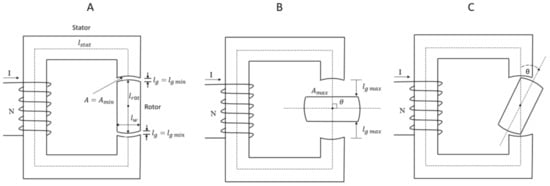
Figure 1.
A simplified magnetic circuit consisting of a stator and rotor. The rotor’s axis is directed perpendicular to the paper plane. (A) The magnetic axis of the stator and that of the rotor is aligned. (B) The magnetic axis of the rotor is perpendicular to the magnetic axis of the stator. (C). There is an angle θ between the magnetic axis of the stator and the rotor [42].
Supposing that the magnetic circuit consists of a stator and a rotor made of the same ferromagnetic soft material, for example iron, with a given relative permeability, μr, as shown in Figure 1; the rotor with magnetic pole pieces at its ends can rotate around its axis directed perpendicular to the paper plane between the pole pieces of the stator. The rotor is the moving part of the magnetic circuit.
Consider case A, Figure 1, where the magnetic axis of the stator and that of the rotor is aligned. The mean lengths of the stator and rotor are ls and lr, respectively. The length of each airgap between the stator and rotor is denoted as lg. The cross-sectional area throughout the magnetic circuit is denoted as A. Suppose a current, I, is flowing through the magnetizing coil with N turns and no fringning.
According to Equation (1), the current through the coil, i.e., the magnetomotive force = NI, will set up a magnetic flux, Φ, through the stator, rotor, and air gaps [42,43]:
where is the reluctance, i.e., the magnetic resistance for the magnetic flux. According to Equation (2), the magnetic flux will flow in closed path within this system. This is similar to Ohm’s law for electric circuits, where NI corresponds to electric potential, Φ to electric current, and to electric resistance.
The reluctance is proportional to the length, l, of the closed path for the flux and inversely proportional to the cross-section, A, of the magnetic circuit, and is given by [42,43]:
where μr = 1 + χmol, where χmol is the magnetic molar susceptibility for the material.
Applied to the system in Figure 1A, the total reluctance for the magnetic circuit will be:
where μr = 1 for air, and lstat and lrot are the mean lengths of the stator and rotor, respectively. In this case, the air gaps have their minimum length, denoted lg min, the cross-section area for the airgaps and rotor is denoted Amin, and the reluctance is denoted min.
Consider case B, Figure 1, where the magnetic axis of the stator is perpendicular to that of the rotor (θ = π/2). Each gap between the stator and the rotor has its maximum length and is denoted lg max. The area of the rotor side facing the flux is denoted Amax. The effective cross-section area for the airgaps and rotor is denoted Aeff. The width of the rotor is denoted lw. Suppose μr is the same for case A and case B. The reluctance denoted max, is given by:
where estimated Aeff = ½ (Amin + Amax).
During each rotor revolution, the length of the airgaps varies between lg min and lg max with minimum values at θ = 0, π, 2π …, and maximum values at θ = π/2, 3π/2, 5π/2… Corresponding variations occur with the reluctance of the magnetic circuit. An illustrative example is given in the following.
Suppose lstat = 0.26 m, lrot = 0.04 m, lw = 0.02 m, lg min = 0.001 m, lg max = 0.01 m,
A = Amin = 0.0004 m2, Amax = 0.0008 m2, μr = 2000, and μ0 = 4π·10−7 H/m.
Aeff = ½(Amin + Amax) = 0.0006 m2.
Inputting the values into Equations (5) and (6), the calculated values of the reluctance when stator and rotor are aligned (θ = 0), min, and when the magnetic axis of the stator is perpendicular to that of the rotor (θ = π/2), max.
000 + 3.980.000 ≈ 4.3·106 H−1
000 + 9.950 + 26.539.000 ≈ 27·106 H−1
Note that the reluctance is dominated by the air gaps and has a minimum value when the length of the air gap has a minimum value, and a maximum value when the length of the air gap has a maximum value. This is mainly because the relative permeability for iron (here, μr = 2000) is much higher than for air (μr = 1).
When the magnetic axis of the stator and that of the rotor is aligned (θ = 0, π, 2π…), (θ) = min. When the magnetic axis of the stator is perpendicular to that of the rotor (θ = π/2, 3π/2, 5π/2…), (θ) = max. Using values for min and max from the example above, and a small value of θ, for example θ = 12°, the reluctance is calculated by Equation (7):
(θ = 12°) = [4.3 + (27 − 4.3)·sin (12)]·106 ≈ 9·106 H−1
Note the doubling of the reluctance of the magnetic circuit already at 12° deviation from the alignment position. This is because iron is ferromagnetic and air is diamagnetic.
2.2. The Minimum Reluctance Principle
To describe the minimum reluctance principle, three states for the rotor position are shown in Figure 2 and described as follows:
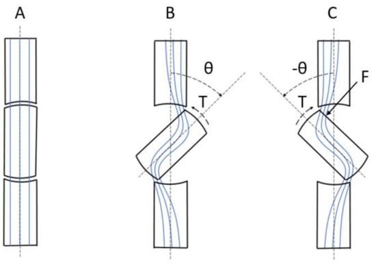
Figure 2.
A segment of the magnetic circuit shown in Figure 1, consisting of the rotor and a small part of the stator. (A) The rotor and stator are aligned. (B) The rotor is turned to an angle θ and then released. (C) The rotor is forced to an angle − θ. The blue lines represent the magnetic flux lines. Positive rotation direction is clockwise.
In Figure 2, a segment of the magnetic circuit is shown. The blue lines represent the magnetic flux lines, and the positive rotation direction is clockwise.
Suppose the initial position of the rotor is as shown in Figure 2A. The rotor and stator are aligned, there are no disturbances of the magnetic flux lines, and the reluctance of the magnetic circuit has a minimum value. There is no net force, or torque, on the rotor.
Then, suppose that the rotor is turned to an angle θ and then released, as shown in Figure 2B. The magnetic flux lines are disturbed and the reluctance of the magnetic circuit has increased, as explained in Section 2.1. The rotor poles are now attracted to the stator poles with by a force, or the electromechanical torque, T [44,45]:
The negative sign means that the torque acts in the direction to bring the magnetic flux of the stator and rotor into alignment [40], i.e., the state in Figure 2A, where the reluctance has a minimum value.
Finally, suppose that a force, or torque, is turning the rotor an angle, −θ, out of position of alignment, as shown in Figure 2C. The magnetic flux lines are disturbed and the reluctance is increased. The rotation is now hindered by the attraction of the rotor poles to the stator poles by the torque, T [44,45]:
The positive sign means that the torque acts in the direction to bring the magnetic flux of the stator and rotor into alignment [40], i.e., the state in Figure 2A, where the reluctance has a minimum value.
The magnetic field always tends to bring the rotor, or the moving part of the magnetic circuit, into the state where the reluctance of the magnetic circuit has a minimum value. This is the minimum reluctance principle [46]. Many kinds of electric machines are based on this principle [47,48].
The minimum reluctance principle implies two mechanisms of interaction:
- The attraction mechanism, where a ferromagnetic, or paramagnetic, moving part is attracted into the magnetic field;
- The hindrance mechanism, where the moving part is hindered from leaving the magnetic field.
3. Results and Discussion
In this section, the magnetic concentration gradient force is analyzed with respect to the minimum reluctance principle. The force will be analyzed by a diffusion system where a paramagnetic electrolyte flows through a thin, inert membrane under influence of a homogeneous magnetic field.
Based on results from previous studies, it is discussed whether the minimum reluctance principle can be applied to mass transfer in the diffusion layer at the electrode/electrolyte interface in two cases: (1) deposition of paramagnetic ions on an electrode surface; and (2) mass transfer of paramagnetic ions from an electrode surface to bulk.
3.1. Diffusion of a Paramagnetic Electrolyte Through a Thin Membrane
This section is based on an experimental study carried out by Waskaas [19], the mathematical model developed by Svendsen and Waskaas [39], and the minimum reluctance principle.
Consider a diffusion system where an unstirred paramagnetic electrolyte is flowing from one chamber (1) with high electrolyte concentration, to another (2) with lower electrolyte concentration, through a thin membrane under influence of a homogeneous static magnetic field, as shown in Figure 3A,B.
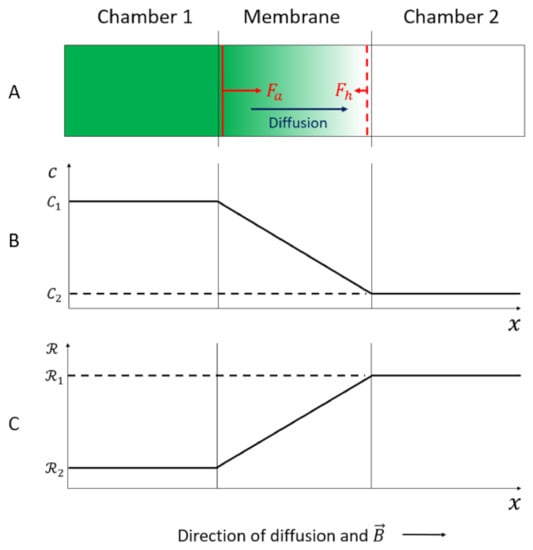
Figure 3.
(A) The diffusion process of an unstirred paramagnetic electrolyte from chamber 1 to chamber 2 through a thin, inert membrane under influence of a homogeneous static magnetic field, . (B) Illustration of the concentration profile from chamber 1 to chamber 2 through the membrane. (C) Illustration of the reluctance profile from chamber 1 to chamber 2 through the membrane [39].
The membrane with thickness 150 μm is mounted vertically. The magnetic field was applied horizontally and perpendicular to the membrane and applied continuously throughout the experiment. It is assumed that the diffusion process is due to two mechanisms: Fick diffusion and migration due to the magnetic concentration gradient force. The flow through the membrane is laminar. The Reynold number in the membrane is calculated to be 10−6 with average velocity of the liquid solution 10−6 m/s, pore diameter 0.22 × 10⁻⁶ m, and kinematic viscosity of the liquid 10−6 m2/s [39]. The concentration gradient is assumed to be limited to the membrane. The magnetic susceptibility of the electrolyte is proportional to its concentration; therefore, the magnetic susceptibility is higher in chamber 1 than in chamber 2. The gradient of the magnetic susceptibility, and consequently, the magnetic concentration gradient force, is assumed to be limited to the membrane as well. The reluctance of the electrolyte is inverse proportional to its magnetic susceptibility (Equation (4)); therefore, the reluctance is lower in chamber 1 than in chamber 2, and shows a gradient in the membrane as well, as shown in Figure 3C.
The reluctance gradient in the membrane corresponds to the moving part, or rotor, of the magnetic circuit, as described in Section 2.2. Consequently, the minimum reluctance principle which implies the two interaction mechanisms, attraction and hindrance, can be applied.
When the electrolyte is flowing into the membrane under influence of the magnetic field, it is attracted by a magnetic force, which tends to fill the membrane with the paramagnetic electrolyte in order to decrease the reluctance in the membrane. This is in accordance with the attraction mechanism of the minimum reluctance principle. The attraction force (Fa) is just the magnetic concentration gradient force, which has the same positive x-direction as in Figure 3, and is given by [39]:
where is the concentration gradient of the paramagnetic electrolyte.
The force corresponding to the torque given in Equation (8).
When the paramagnetic electrolyte flows out of the membrane, it is hindered by the magnetic concentration gradient force in order to hinder an increase in the reluctance in the membrane. This is in accordance with the hindrance mechanism of the minimum reluctance principle. The hindrance force (Fh) has the opposite direction from the positive x-direction in Figure 3, and is given by [39]:
This force corresponds to the torque given in Equation (9).
Initially, and during the first part of the diffusion process, the concentration gradient at the inlet of the membrane is extremely high, and the magnetic concentration gradient force plays a significant role for the diffusion process. The force tends to fill the membrane with the paramagnetic electrolyte in order to decrease the reluctance, which is in accordance with the attraction mechanism of the minimum reluctance principle (Section 2.2).
As chamber 2 is filled with electrolyte, the concentration gradient decreases, and hence, both the magnetic concentration gradient forces, Fa and Fh, are diminished. At equilibrium, there is no concentration gradient, i.e., no reluctance gradient, in the membrane, and consequently, no magnetic concentration gradient force. Therefore, the magnetic concentration gradient force is elusive, which is in accordance with the obtained experimental results [19,31].
The direction of the magnetic field relative to the x-axis (Figure 3) is irrelevant for the direction of the magnetic concentration gradient force, because it is proportional to the B square (Equations (10) and (11)). This is confirmed by experimental results [26,32,37] as well.
According to Svendsen and Waskaas [39], the magnetic concentration gradient force attracts the paramagnetic electrolyte flowing into the membrane. However, based on the reasoning presented above, it is emphasized that it is the attraction mechanism of the minimum reluctance principle which dominates the magnetic field effect in these experiments.
The diffusion system is classified as a closed–open vessel, which means that close to the membrane inlet in chamber 1, there is a convective flow. However, both chamber 1 and chamber 2 are regarded as ideal mixing tanks in the model. This is not true in the beginning of the process in each experiment, but appears to be a good approximation after some minutes [39]. The experiments were not designed for convection studies [19]; therefore, it is not relevant to estimate either the Schmidt number or the Sherwood number for this process in order to compare these values with results from Lorentz force studies in the literature.
To summarize, when a paramagnetic electrolyte flows into a range with a concentration gradient, and hence, a reluctance gradient, under the influence of a homogeneous magnetic field, the magnetic concentration gradient force acts on the flow in such a way that the reluctance in the range is minimized. According to the minimum reluctance principle, the force acts by two interaction mechanisms: (1) attraction of the paramagnetic electrolyte flowing into the range in order to decrease the reluctance; and (2) hindrance of the paramagnetic electrolyte flowing out of the range in order to hinder an increase in the reluctance.
3.2. Deposition of Paramagnetic Ions on an Electrode Surface
This section is based on some comprehensive studies carried out by Krause et al. [26,34] and Uhlemann et al. [28,32] concerning magnetic field effects on the deposition of paramagnetic ions on electrode surfaces. The discussion is focused on just those results where it is concluded that the magnetic concentration gradient force is dominating.
Krause et al. [26,34] studied the deposition of paramagnetic Co, Ni, and Cu ions on a vertical plane Au electrode (diamagnetic) in corresponding metal sulphate solutions in magnetic fields. A homogeneous magnetic field, up to 1.2 T, was introduced horizontally, perpendicular to the plane electrode surface. They found that the magnetic field caused a decrease in the depositions of Co and Cu, but not of Ni. They argued that the deposition of Co and Cu are diffusion-controlled, while it is mixed-controlled for Ni (activation-controlled at the beginning and diffusion-controlled after some seconds) and therefore a low concentration gradient in the diffusion layer. Consequently, the reluctance gradient in the diffusion layer is low, and the magnetic concentration gradient force has negligible effect on the deposition.
In addition, experiments where the magnetic field was oriented parallel to the electrode surface were also carried out. It was found that the magnetic field caused an increase in the depositions of all three kinds of ions. It was concluded that the latter effect was due to the Lorentz force and convection phenomena, while the former effect was dominated by the magnetic concentration gradient force. The effects were not discussed in terms of the Schmidt and Sherwood numbers.
The following discussion is focused on the magnetic concentration gradient force that arises as a consequence of the minimum reluctance principle.
The experimental setup and design for the present deposition experiments and the diffusion experiments, described in Section 3.1, are different. The former involves an electrode/electrolyte interface, the latter a membrane.
Despite the differences, however, the following reasoning shows that the magnetic reluctance principle, and hence, the magnetic concentration gradient force, given in Equations (10) and (11), can be applied to the mass transfer in the electrode/electrolyte interface as well.
During the deposition process, there is a mass transfer of paramagnetic electrolytes from bulk to the electrode surface where the paramagnetic ions are consumed. The electrolyte concentration and density near the vertical electrode are lower than in the bulk, i.e., a concentration profile arises from the electrode surface toward bulk, as shown in Figure 4 [49,50].
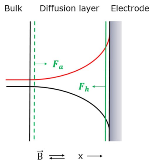
Figure 4.
Illustration of concentration profile (black) [49,50] and reluctance profile (red) for deposition of the paramagnetic metal ions on an electrode surface. Fa and Fh (green) represents the magnetic concentration gradient force. The magnetic field, , was applied perpendicular to the electrode surface. Positive x-direction is indicated.
This electrode/electrolyte interface is denoted the diffusion layer [50] and has a typical thickness of 30 μm [10].
The shape of the concentration profile will cause an upward flow near the electrode, i.e., free convection [10], which may interact with applied magnetic fields. According to Krause et al. [26,34], however, this interaction was neglectable in their experiments.
Concerning electrochemical electrode kinetics, results of comprehensive reviews show that there is no evidence for magnetic field effects on electrochemical kinetics [5,6].
Accordingly, it is assumed that the measured magnetic field effects are due to an interaction between the magnetic field and the mass transfer of electrolyte in the diffusion layer where there is a concentration gradient of the paramagnetic electrolyte. The authors indicate that this concentration gradient corresponds to the concentration gradient in the membrane for the diffusion experiments, described in Section 3.1. Consequently, it is assumed that the magnetic concentration gradient force, given in Equations (10) and (11), can be applied to the mass transfer in the diffusion layer for the present deposition experiments. This applies to the minimum reluctance principle as well.
According to the reluctance argumentation for the paramagnetic electrolyte in Section 3.1, the concentration profile in the diffusion layer causes a reluctance profile in the diffusion layer, as shown in Figure 4.
During the deposition process, paramagnetic electrolyte is flowing from bulk into the diffusion layer and then, out of the diffusion layer for the deposition on the electrode surface.
When the electrolyte containing paramagnetic ions, Co2+ respective Cu2+, is flowing into the diffusion layer under influence of the magnetic field, it is attracted by the magnetic concentration gradient force which tends to fill the diffusion layer with the paramagnetic electrolyte in order to decrease the reluctance. The attraction force (Fa), which is based on the minimum reluctance principle, has the same direction as the positive x-direction and is given in Equation (10) and shown in Figure 4.
When the paramagnetic ions tend to flow out of the diffusion layer for deposition on the electrode surface under influence of the magnetic field, they are hindered by the magnetic concentration gradient force in order to hinder an increase in the reluctance in the diffusion layer. The hindrance force (Fh), which is based on the minimum reluctance principle, has the opposite direction as the positive x-direction and is given in Equation (11) and shown in Figure 4.
The experimental results show a decrease in the deposition of paramagnetic ions under the influence of magnetic fields; therefore, it indicates that the magnetic concentration gradient force hinders the flow out of the diffusion layer for the deposition process. Accordingly, it appears that it is the hindrance mechanism of the minimum reluctance principle that dominates the magnetic field effect in these experiments.
Uhlemann et al. [28,32] studied the deposition of paramagnetic Co ions on horizontal Cu plane electrodes (diamagnetic) in CoSO4 solutions in magnetic fields. A homogeneous magnetic field, up to 13 T, was introduced perpendicular to the plane electrode surface. Two types of cell geometry were used: a flat embedded electrode and a wall electrode which was expected to influence the convection close to the surface. The principle setup is shown in Figure 5.
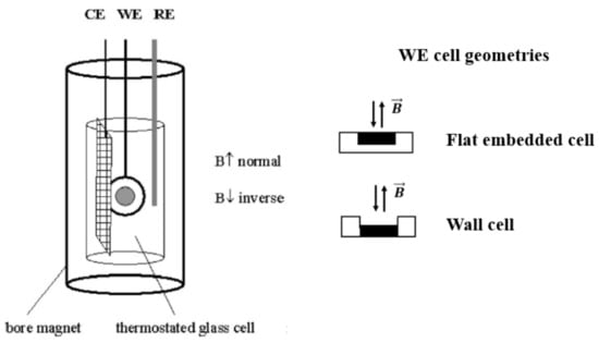
Figure 5.
Principle experimental setup. The two working cell geometries used were a flat embedded electrode and a wall electrode. CE is the counter electrode, WE is the working electrode, and RE is the reference electrode. The magnetic field was applied as indicated [28,32].
The experimental methods used were cyclic voltammetry and electrochemical quartz crystal micro-balance (EQCM).
The results show that the current efficiency for the Co deposition on the flat embedded electrode increased for the increasing magnetic flux densities.
This holds for both directions of the magnetic field. For the wall electrode, the results show that the current efficiency for the Co deposition decreased with increasing magnetic flux densities. This holds for both directions of the magnetic field as well.
The authors concluded that results for the flat embedded electrode are mainly explained by macro-magnetoconvection. For the wall electrode where the macro-convection is diminished, the results are explained in terms of the magnetic concentration gradient force. The effects were not discussed in terms of the Schmidt and Sherwood numbers.
The following discussion is therefore focused on the results for the horizontal orientated wall electrode.
Macro-convection is diminished for the wall electrode; therefore, similar diffusion layer with concentration and reluctance profiles as those shown in Figure 4 for the vertical electrode, are assumed to arise at the surface of the horizontal electrode. Due to the reasoning above, it is assumed that the minimum reluctance principle, and hence, the magnetic concentration gradient force given in Equations (10) and (11), can be applied to the mass transfer in the diffusion layer for the wall electrode.
The experimental results show a decrease in the deposition of paramagnetic ions under influence of magnetic fields, which indicates that the magnetic concentration gradient force hinders the flow out of the diffusion layer for the deposition process on the electrode.
Accordingly, it appears that it is the hindrance mechanism of the minimum reluctance principle that dominates the magnetic field effect in these experiments.
3.3. Mass Transfer of Paramagnetic Ions from an Electrode Surface
This section is based on some studies carried out by Leventis and Dass [31] and Leventis and Gao [23], concerning magnetic field effects on the mass transfer of paramagnetic ions from an electrode surface to bulk. The authors explain the effects in favor of the magnetic concentration gradient force. The effects will be discussed in terms of the minimum reluctance principle.
Leventis and Dass [31] and Leventis and Gao [23] demonstrated that paramagnetic ions produced by an electrode, form a diffusion layer with the highest concentration at the electrode/electrolyte interface and fade away in the bulk by natural, or free, convection. When a homogeneous magnetic field T was applied perpendicular to the electrode surface, the paramagnetic ions were held close to the electrode surface.
One experiment was designed as follows [31]. A cylindrical-shaped Au electrode (diamagnetic) was immersed in a CH3CN solution of nitrobenzene (NB). NB was reduced by the electrode into the red colored paramagnetic Cyclic voltammetry was used. A homogeneous magnetic field, 3.3 T, was introduced perpendicular to the end of the horizontal orientated cylinder, as shown in Figure 6.
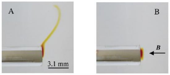
Figure 6.
Photos of the horizontal orientated cylinder electrode in the nitrobenzene (NB) solution with (B) and without (A) exposure of the magnetic field. The direction of the magnetic field is indicated [31].
The results are shown in Figure 6B,A, with and without the magnetic field, respectively. In Figure 6A, the produced paramagnetic ions form a diffusion layer with highest concentration at the electrode/electrolyte interface and fade away in the bulk due to free convection. In Figure 6B, the paramagnetic layer is held close to the electrode by the magnetic field. The authors concluded that the force which must oppose the free convection is the magnetic concentration gradient force.
Similar results were obtained using a redox-active substance such as TMPD (Tetramethyl–phenylenediamine), which generates paramagnetic radical TMPD+ at the electrode [23].
Due to the reasoning given in Section 3.2., it is assumed that the minimum reluctance principle, and hence, the magnetic concentration gradient force, given in Equations (10) and (11), can be applied to the mass transfer in the diffusion layer for the present experiments.
During the formation, the concentration and reluctance profiles in the diffusion layer are as illustrated in Figure 7.
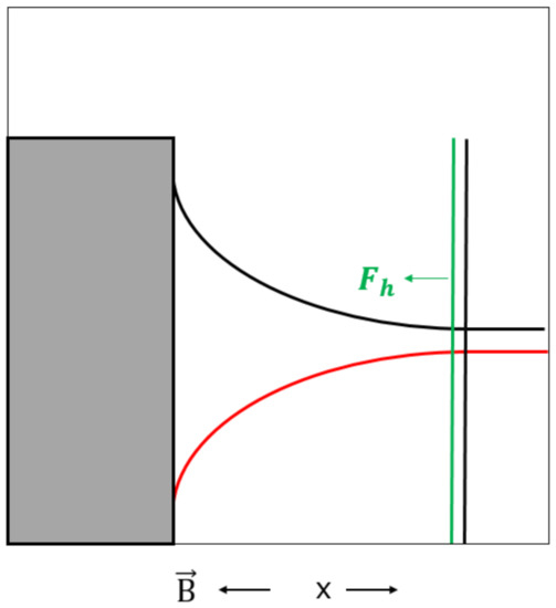
Figure 7.
Illustration of concentration profile (black) and reluctance profile (red) in the diffusion layer. Fh (green) represents the magnetic concentration gradient force. The magnetic field, , was applied perpendicular to the electrode surface. Positive x-direction is indicated.
When the paramagnetic electrolyte containing NB− ions tends to flow out of the diffusion layer by free convection under influence of the magnetic field, it is hindered by the magnetic concentration gradient force in order to hinder an increase in the reluctance in the diffusion layer. The hindrance force (Fh) which is based on the minimum reluctance principle, has the opposite direction as the positive x-direction, and is given in Equation (11) and shown in Figure 7. According to Ragsdale and White [51], the magnetic concentration gradient force and free convection are of the same order of magnitude.
Accordingly, it appears that it is the hindrance mechanism of the minimum reluctance principle that dominates the magnetic field effect in these experiments.
4. Conclusions
The magnetic concentration gradient force arises as a consequence of the minimum reluctance principle given by the magnetic circuit theory.
The minimum reluctance principle implies two mechanisms of interaction: attraction of a ferromagnetic moving part into a magnetic field and hindrance of this moving part from leaving the magnetic field.
Applied to a diffusion system, the moving part corresponds to the concentration gradient, and hence, the reluctance gradient, in the membrane.
In a diffusion system, the magnetic concentration gradient force acts on the flow in such a way that the reluctance in the membrane is minimized.
The force implies two interaction mechanisms: attraction of the paramagnetic electrolyte flowing into the membrane in order to decrease the reluctance, and hindrance of the paramagnetic electrolyte flowing out of the membrane in order to hinder an increase in the reluctance.
Results of the discussion of some selected studies show that the minimum reluctance principle can be applied to mass transfer into or out of the diffusion layer at electrode/electrolyte interfaces in magnetic fields as well.
Funding
This research received no external funding.
Institutional Review Board Statement
Not applicable.
Informed Consent Statement
Not applicable.
Acknowledgments
Discussions with John Arild Svendsen, Faculty of Technology, Natural Sciences and Maritime Sciences, University of South-Eastern Norway, are gratefully acknowledged.
Conflicts of Interest
The author declares no conflict of interest.
Nomenclature
| A | Area (m2) |
| B | Magnetic flux density (T) |
| c | Electrolyte concentration (mol/m3) |
| F | Force (N) |
| I | Electric current (A) |
| K | Constant (dimensionless) |
| l | Length (m) |
| N | Number of turns (dimensionless) |
| r | Position vector (m) |
| Reluctance (H−1) | |
| Re | Reynolds number (dimensionless) |
| Sc | Schmidt number (dimensionless) |
| Sh | Sherwood number (dimensionless) |
| T | Torque (Nm) |
| x | Position (m) |
| θ | Angle (°) |
| μ | Magnetic permeability (H/m) |
| Φ | Magnetic flux (Wb) |
| χ | Magnetic susceptibility (dimensionless) |
| 0 | Reference value |
| 1 | Chamber 1 |
| 2 | Chamber 2 |
| a | Attraction |
| eff | Effective |
| g | Gap |
| h | Hindrance |
| max | Maximum |
| min | Minimum |
| mol | Molar |
| r | Relative |
| rot | Rotor |
| stat | Stator |
| total | Total |
| w | Width |
References
- Fahidy, T.Z. Magnetoelectrolysis. J. Appl. Electrochem. 1983, 13, 553–563. [Google Scholar] [CrossRef]
- Tacken, R.R.; Janssen, L.J.J. Applications of magnetoelectrolysis. J. Appl. Electrochem. 1995, 25, 1–5. [Google Scholar] [CrossRef]
- Fahidy, T.Z. The effect of magnetic fields on electrochemical processes. Electrodepos. Surf. Finish. 2005, 32, 333–354. [Google Scholar] [CrossRef]
- Hinds, G.; Coey, J.; Lyons, M. Influence of magnetic forces on electrochemical mass transport. Electrochem. Commun. 2001, 3, 215–218. [Google Scholar] [CrossRef]
- Alemany, A.; Chopart, J.P. An Outline of Magnetoelectrochemistry. In Magnetohydrodynamics—Historical Evolution and Trends; Molokov, S., Moreau, R., Moffatt, H.K., Eds.; Springer: Dordrecht, The Netherlands, 2007; pp. 391–407. [Google Scholar]
- Monzon, L.M.A.; Coey, J.M.D. Magnetic fields in electrochemistry: The Lorentz force. A mini-review. Electrochem. Commun. 2014, 42, 38–41. [Google Scholar] [CrossRef]
- Song, K.; Wu, S.; Tagawa, T.; Shi, W.; Zhao, S. Thermomagnetic convection of paramagnetic gas in an enclosure under no gravity condition. Fluids 2019, 4, 49. [Google Scholar] [CrossRef]
- Tagawa, T. Numerical analysis of magnetohydrodynamic flows. Fluids 2020, 5, 23. [Google Scholar] [CrossRef]
- Levich, G. Physicochemical Hydrodynamics; Prentice Hall: Englewood Cliffs, NJ, USA, 1962; pp. 60–72, 286–293. [Google Scholar]
- Newman, J.; Thomas-Alyea, K.E. Electrochemical Systems, 3rd ed.; John Wiley & Sons: Hoboken, NJ, USA, 2004; pp. 172–177, 340–358, 400–403. [Google Scholar]
- Shevchuk, I.V. Modelling of Convective Heat and Mass Transfer in Rotating Flows; Springer Science and Business Media LLC: Cham, Switzerland, 2016; pp. 145–170. [Google Scholar]
- Braithwaite, D.; Beaugnon, E.; Tournier, R. Magnetically controlled convection in a paramagnetic fluid. Nature 1991, 354, 134–136. [Google Scholar] [CrossRef]
- Ragsdale, S.R.; Grant, K.M.; White, H.S. Electrochemically generated magnetic forces. Enhanced transport of a paramagnetic redox species in large, nonuniform magnetic fields. J. Am. Chem. Soc. 1998, 120, 13461–13468. [Google Scholar] [CrossRef]
- Sugiyama, A.; Hashiride, M.; Morimoto, R.; Nagai, Y.; Aogaki, R. Application of vertical micro-disk MHD electrode to the analysis of heterogeneous magneto-convection. Electrochim. Acta 2004, 49, 5115–5124. [Google Scholar] [CrossRef]
- Mutschke, G.; Tschulik, K.; Weier, T.; Uhlemann, M.; Bund, A.; Fröhlich, J. On the action of magnetic gradient forces in micro-structured copper deposition. Electrochim. Acta 2010, 55, 9060–9066. [Google Scholar] [CrossRef]
- Yang, X.; Tschulik, K.; Uhlemann, M.; Odenbach, S.; Eckert, K. Magnetic separation of paramagnetic ions from initially homogeneous solutions. IEEE Trans. Magn. 2014, 50, 1–4. [Google Scholar] [CrossRef]
- Pleskacz, Ł; Fornalik-Wajs, E. Identification of the structures for low reynolds number flow in the strong magnetic field. Fluids 2019, 4, 36. [Google Scholar] [CrossRef]
- O’Brian, R.N.; Santhanam, K.S.V. Electrochemical hydrodynamics in a magnetic field with laser interferome-try. Electrochim. Acta 1987, 32, 1679–1691. [Google Scholar]
- Waskaas, M. Short-term effects of magnetic fields on diffusion in stirred and unstirred paramagnetic solutions. J. Phys. Chem. 1993, 97, 6470–6476. [Google Scholar] [CrossRef]
- Waskaas, M. Magnetic field effect on electrode reactions. I. Effects on the open-circuit potential of electrodes in solutions of different magnetic properties. Acta Chem. Scand. 1996, 50, 516–520. [Google Scholar] [CrossRef][Green Version]
- Mogi, K.; Sakihama, T.; Hirota, N.; Kitazawa, K. Magnetic field effect on the transport process of paramagnetic or diamagnetic substances in the aqueous solution. J. Appl. Phys. 1999, 85, 5714–5716. [Google Scholar] [CrossRef]
- Waskaas, M.; Kharkats, Y.I. Magnetoconvection phenomena: A mechanism for influence of magnetic fields on electrochemical processes. J. Phys. Chem. B 1999, 103, 4876–4883. [Google Scholar] [CrossRef]
- Leventis, N.; Gao, X. ND−Fe−B permanent magnet electrodes. Theoretical evaluation and experimental demonstration of the paramagnetic body forces. J. Am. Chem. Soc. 2002, 124, 1079–1088. [Google Scholar] [CrossRef]
- Perov, N.S.; Sheverdyaeva, P.M.; Inoue, M. Effect of magnetic field on the electrode potential of metals. J. Appl. Phys. 2002, 91, 8557. [Google Scholar] [CrossRef]
- Ručinskien, A.; Bikulčius, G.; Gudavičiūt, L.; Juzeliūnas, E. Magnetic field effect on stainless steel corrosion in FeCl3 solution. Electrochem. Commun. 2002, 4, 86–91. [Google Scholar] [CrossRef]
- Krause, A.; Uhlemann, M.; Gebert, A.; Schultz, L. The effect of magnetic fields on the electrodeposition of cobalt. Electrochim. Acta 2004, 49, 4127–4134. [Google Scholar] [CrossRef]
- Rabah, K.; Chopart, J.-P.; Schloerb, H.; Saulnier, S.; Aaboubi, O.; Uhlemann, M.; Elmi, D.; Amblard, J. Analysis of the magnetic force effect on paramagnetic species. J. Electroanal. Chem. 2004, 571, 85–91. [Google Scholar] [CrossRef]
- Uhlemann, M.; Schlörb, H.; Msellak, K.; Chopart, J.-P. Electrochemical deposition of CU under superimposition of high magnetic fields. J. Electrochem. Soc. 2004, 151, C598–C603. [Google Scholar] [CrossRef]
- Bund, A.; Kuehnlein, H.H. Role of magnetic forces in electrochemical reactions at microstructures. J. Phys. Chem. B 2005, 109, 19845–19850. [Google Scholar] [CrossRef]
- Dass, A.; Counsil, J.A.; Gao, X.; Leventis, N. Magnetic field effects on the open circuit potential of ferromagnetic electrodes in corroding solutions. J. Phys. Chem. B 2005, 109, 11065–11073. [Google Scholar] [CrossRef]
- Leventis, N.; Dass, A. Demonstration of the elusive concentration-gradient paramagnetic force. J. Am. Chem. Soc. 2005, 127, 4988–4989. [Google Scholar] [CrossRef] [PubMed]
- Uhlemann, M.; Krause, A.; Chopart, J.P.; Gebert, A. Electrochemical deposition of CO under the influence of high magnetic fields. J. Electrochem. Soc. 2005, 152, C817–C826. [Google Scholar] [CrossRef]
- Coey, J.M.D.; Rhen, F.M.F.; Dunne, P.; McMurry, S. The magnetic concentration gradient force—Is it real? J. Solid State Electrochem. 2007, 11, 711–717. [Google Scholar] [CrossRef]
- Krause, A.; Koza, J.; Ispas, A.; Uhlemann, M.; Gebert, A.; Bund, A. Magnetic field induced micro-convective phenomena inside the diffusion layer during the electrodeposition of Co, Ni and Cu. Electrochim. Acta 2007, 52, 6338–6345. [Google Scholar] [CrossRef]
- Lioubashevski, O.; Katz, E.; Willner, I. Effects of magnetic field directed orthogonally to surfaces on electrochemical processes. J. Phys. Chem. C 2007, 111, 6024–6032. [Google Scholar] [CrossRef]
- Weier, T.; Eckert, K.; Mühlenhoff, S.; Cierpka, C.; Bund, A.; Uhlemann, M. Confinement of paramagnetic ions under magnetic field influence: Lorentz versus concentration gradient force based explanations. Electrochem. Commun. 2007, 9, 2479–2483. [Google Scholar] [CrossRef]
- Aaboubi, O.; Douglade, J. Application of magnetic field to control mass transport process during silver cementation on copper. J. Electroanal. Chem. 2013, 693, 42–50. [Google Scholar] [CrossRef]
- Yu, Y.; Song, Z.; Ge, H.; Wei, G.; Jiang, L. Effects of magnetic fields on the electrodeposition process of Cobalt. Int. J. Electrochem. Sci. 2015, 10, 4812–4819. [Google Scholar]
- Svendsen, J.A.; Waskaas, M. Mathematical modelling of mass transfer of paramagnetic ions through an inert membrane by the transient magnetic concentration gradient force. Phys. Fluids 2020, 32, 013606. [Google Scholar] [CrossRef]
- Zhang, X.; Wang, Z.; Zhou, Z.; Yang, G.; Cai, X. Impact of magnetic field on corrosion performance of Al–Mg alloy with different electrode potential phases. Intermetallics 2021, 129, 107037. [Google Scholar] [CrossRef]
- Wolfson, R. Essential University Physics, 2nd ed.; Pearson: Essex, UK, 2014; Volume 2, pp. 133–148, 216–219. [Google Scholar]
- El-Hawary, M.E. Principles of Electric Machines with Power Electronic Applications, 2nd ed.; John Wiley & Sons: New York, NY, USA, 2002; pp. 23–77. [Google Scholar]
- Boylestad, R.L. Introductory Circuit Analysis, 13th ed.; Pearson: Boston, MA, USA, 2016; pp. 543–561. [Google Scholar]
- Fitzgerald, A.E.; Kingsley, C., Jr.; Umans, S.D. Electric Machinery, 6th ed.; MCGraw-Hill: New York, NY, USA, 2003; pp. 1–9, 214–221. [Google Scholar]
- Electric Machines, Torque. Available online: https://people.ucalgary.ca/~aknigh/electrical_machines/fundamentals/f_ac_torque.html (accessed on 22 February 2021).
- Mablekos, V.E. Electric Machine Theory for Power Engineers, 1st ed.; Harper and Row: New York, NY, USA, 1980; pp. 384–394. [Google Scholar]
- Gan, C.; Wu, J.; Sun, Q.; Kong, W.; Li, H.; Hu, Y. A review on machine topologies and control techniques for low-noise switched reluctance motors in electric vehicle applications. IEEE Access 2018, 6, 31430–31443. [Google Scholar] [CrossRef]
- Hu, W.; Zhang, X.; Yin, H.; Geng, H.; Zhang, Y.; Shi, L. Analysis of magnetic field and electromagnetic performance of a new hybrid excitation synchronous motor with dual-V type magnets. Energies 2020, 13, 1501. [Google Scholar] [CrossRef]
- Wendt, H.; Kreysa, G. Electrochemical Engineering, 1st ed.; Springer-Verlag: Berlin, Germany, 1999; pp. 97–98. [Google Scholar]
- Tobias, C.W.; Eisenberg, M.; Wilke, C.R. Diffusion and convection in electrolysis—A theoretical review. J. Electrochem. Soc. 1952, 99, 359C–365C. [Google Scholar] [CrossRef]
- Ragsdale, S.R.; White, H.S. Imaging microscopic magnetohydrodynamic flows. Anal. Chem. 1999, 71, 1923–1927. [Google Scholar] [CrossRef]


Publisher’s Note: MDPI stays neutral with regard to jurisdictional claims in published maps and institutional affiliations. |
© 2021 by the author. Licensee MDPI, Basel, Switzerland. This article is an open access article distributed under the terms and conditions of the Creative Commons Attribution (CC BY) license (http://creativecommons.org/licenses/by/4.0/).