Abstract
Many thermohydraulic issues about the safety of light water reactors are related to complicated two-phase flow phenomena. In these phenomena, computational fluid dynamics (CFD) analysis using the volume of fluid (VOF) method causes numerical diffusion generated by the first-order upwind scheme used in the convection term of the volume fraction equation. Thus, in this study, we focused on an interface compression (IC) method for such a VOF approach; this technique prevents numerical diffusion issues and maintains boundedness and conservation with negative diffusion. First, on a sufficiently high mesh resolution and without the IC method, the validation process was considered by comparing the amplitude growth of the interfacial wave between a two-dimensional gas sheet and a quiescent liquid using the linear theory. The disturbance growth rates were consistent with the linear theory, and the validation process was considered appropriate. Then, this validation process confirmed the effects of the IC method on numerical diffusion, and we derived the optimum value of the IC coefficient, which is the parameter that controls the numerical diffusion.
1. Introduction
Many thermohydraulic issues related to the safety of light water reactors arise from complicated two-phase flow phenomena such as pool scrubbing, which is an effective measure to filter out radioactive aerosols in severe accidents, and counter-current flow limitation (CCFL), which occurs within the hot leg in pressurized water reactor accidents. Reactor safety evaluation requires a detailed understanding of such phenomena under various accident conditions, and computational fluid dynamics (CFD) is being increasingly used to predict these phenomena [1,2,3].
Nowadays, two-phase CFD analysis with a two-fluid model is often applied to nuclear systems. The two-fluid model is excellent for predicting two-phase flow phenomena with a mesh larger than a bubble or droplet diameter; however, due to the interface structure loss that results from averaging, the constitutive equations for each of the flow regimes are needed to close the basic equations for both the gas and liquid phases. Thus, the approach based on this model is still not applicable for all flow regimes and can only simulate the individual flow behavior of each flow regime (dispersed bubble or droplet flow and separate-phase flow) [4]. On the other hand, methods such as the volume of fluid (VOF) method [5], the level-set method [6], and the front-tracking method [7] are unaffected by flow regime and can track a transitional interface structure. These techniques calculate the interface geometry directly without requiring the constitutive equations. Among them, the VOF method determines interface deformation by focusing on the transport of the fluid volume fraction. However, in the actual calculation, a fluid volume fraction profile diffuses spatially in the first-order upwind scheme (resulting in numerical diffusion) [8]. Therefore, there are multiple variants of the VOF method: there is the kind of VOF method based on interface reconstruction to prevent numerical diffusion, known as the geometric VOF; there is the simple linear interface calculation (SLIC)-VOF method [9], which constitutes the interface as the horizontal or vertical surface; the piecewise linear interface calculation (PLIC)-VOF method [10], which considers the interface gradient and the preservation of mass convection; the coupled level set and volume of fluid (CLSVOF) method [11], which improves the computations for interface curvature and normal direction by coupling the VOF method with the level set (LS) method; and the weighted linear interface calculation (WLIC)-VOF method [12], which simply reconstructs the interface like the SLIC-VOF method and obtains the accurate interface shape like the PLIC-VOF method. The results obtained with these methods are more precise, but the algorithms are complicated in order to preserve mass conservation and interface sharpness. In contrast, the VOF method, which solves the volume fraction equation accurately without interface reconstruction, is called the high-resolution schemes and the algebraic VOF. Within this category, the compressive interface capturing scheme for arbitrary meshes (CICSAM) scheme [13] and the high-resolution interface capturing (HRIC) scheme [14] capture the interface position without introducing numerical diffusion and keep the values of the variables bounded. The CICSAM and HRIC schemes prevent numerical diffusion and maintain the interface’s sharpness, but both have the drawback of generating non-physical errors, such as overshoots and undershoots of the fluid volume fraction.
Here, we focus on another high-resolution scheme; namely, an interface compression (IC) method [15]. It presents an artificial compression term in the volume fraction equation and gives a negative diffusion coefficient, compressing the volume fraction profile in the direction normal to the fluid interface; hence, it can prevent interface dispersal due to numerical diffusion and maintain boundedness and conservation of the phase fraction [15]. The magnitude of its compressive effect depends on the mesh resolution and the IC coefficient (a parameter of the artificial compression term). So far, many analyses have been performed concerning the mesh resolution and the IC coefficient [16,17,18,19,20]. Deshpande et al. [17] noted parasitic (spurious) currents [21] produced by the IC method in the flow dominated by surface tension. Parasitic currents are strong non-physical vortices near the interface that occur without being externally forced by errors in the interface curvature calculation or by an imbalance between the surface tension force and the pressure gradient. These problems usually arise in fluids with high-density ratios (classified as having a density ratio of , where the liquid density is represented as and the gas density is represented as ) when static bubbles and droplets are simulated [22]. Hoang et al. [23] investigated the influence of the IC coefficient on maximum velocity, interface thickness, and parasitic currents and confirmed that a condition with an IC coefficient of 1 is the best condition to prevent both parasitic currents and numerical diffusion; they also demonstrated the role of cell size in determining the IC coefficient condition. Shonibare and Wardle [24] developed the solver, switching the IC coefficient from 1 to 0 based on the calculated interface curvature of a spherical fluid particle (defined as the inverse of the sphere radius dependent on the bubble and mesh sizes). Anez et al. [25] switched the IC coefficient using two criteria: the ratio between minimum interface and actual interface and the grid dependent based on interface resolution quality. Lee and Rhee [26] implemented a dynamic IC method, which is currently drawing much attention, into SNUFOAM-6DOF, which can calculate the 6 degrees of freedom of a ship’s motion to derive the IC coefficient from cell size and flow velocity. However, there are still no strategies to define the general IC coefficient [27].
In this study, to investigate the effect of the general IC method, we tried to validate it by comparing the amplitude growth of the disturbed interfacial wave between a plane gas sheet and a stagnated liquid with the linear theory. This interfacial wave is typical behavior of stratified two-phase flow affected by Kelvin–Helmholtz instability. We targeted the case less affected by parasitic currents and focused only on the numerical diffusion caused by the method. First, we verified the reliability of this validation process and studied the influences of the initial velocity and the Weber number. Then, we evaluated the effects of the mesh resolution and the IC method on numerical diffusion by using this validation process to select the optimum IC coefficient. These effects are worth noting because the fluid interface is subject to numerical diffusion in all stratified simulations [28,29,30,31].
2. Linear Theory
The linear theory developed by Li and Bhunia [32] is summarized here. Consider a base flow field being a two-dimensional (2D) inviscid gas sheet of uniform thickness and density , injected at uniform velocity and pressure into a quiescent liquid phase of pressure , density , viscosity , and dynamic viscosity . The gas–liquid interface is maintained by a constant surface tension . The gravity and compressibility effects are neglected.
In stability analysis, the base flow is disturbed by small perturbations, whose velocity and pressure are, respectively, and at a time (the subscript is replaced by and to denote the gas and the liquid phase, correspondingly). As shown in Figure 1, the upper and lower disturbed gas–liquid interfaces are represented as and ( is the disturbance amplitude), respectively, where the phase angle difference between two surface waves is 0.

Figure 1.
Schematic of the liquid sheet and the surface waves.
The governing equations for this linear theory are listed as follows.
The continuity equation is:
The momentum equation is:
where 1 for (gas) and 0 for (liquid), and is the density.
The kinematic and dynamic boundary conditions are expressed, respectively, as:
and
Due to the inviscid assumption for the gas phase, the shear stress at the interface is given by:
The effect of disturbances far away from the interfaces () should remain bounded. To solve these equations, a normal mode solution assuming the disturbance is sought in the following form:
where and are the stream functions for the gas and the liquid phase, respectively, is the eigenvalue, and is the initial disturbance amplitude (which is much smaller than ). We assume that is smaller than a wavelength , allowing , where is the wavenumber. By substituting Equation (6) into Equations (1) and (2) considering the boundary conditions Equations (3) and (5), Equation (4) becomes dimensionless as follows:
where is the dimensionless eigenvalue, is the dimensionless wavenumber, is the density ratio, is the Reynolds number, and is the gas Weber number. is also expressed as a complex variable , where the real part is the growth rate ( is limited to situations where 0, indicating that the flow is unstable) and the imaginary part is frequency. For gas sheets in an inviscid liquid (), in Equation (7) is:
and is
3. CFD Analysis
The numerical study was performed using OpenFOAM ver.2.3.0 (OpenFOAM Foundation Inc., London, UK), an open-source code developed by the OpenFOAM Foundation [33].
3.1. Governing Equations
The governing equations for incompressible and isothermal laminar flows are as follows [15].
The continuity equation is:
The momentum equation is expressed as:
where ρ is the fluid density, is the velocity vector, is the fluid pressure, is the viscosity coefficient, is the gravitational acceleration, and is the surface tension force. and are defined by the liquid fraction as:
and
where the subscripts and denote the liquid and the gas phase, respectively. is expressed as:
The parameter , defined by a surface tension (CSF model), is given by:
where is the interface curvature. The turbulent model was not used in the present study.
These equations are discretized via the finite volume method. We used the PIMPLE algorithm for coupling the velocity field with the pressure field, which is a combination of the pressure implicit in the splitting of operators (PISO) [34] and the semi-implicit method for pressure linked equations (SIMPLE) [35]. The discretization schemes are used as follows: the first-order Euler implicit scheme is used in time derivative terms, the second-order linear scheme is used in the pressure gradient term, the second-order linear-upwind scheme is used in the divergence term, the second-order linear scheme is used in the Laplacian term, and the first-order non-orthogonal correlation scheme is used in the surface normal gradient term. The time step was automatically controlled based on the maximum Courant number of 0.3. This is because an upper limit of 0.5 is recommended, and the VOF method is more responsive to the Courant number than are standard fluid flow calculations, as shown in the OpenFOAM user guide [33].
3.2. IC Method
The volume fraction equation (advection equation) of the VOF method proposed by Hirt and Nichols [5] is expressed as:
The volume fraction equation is solved separately for each fluid phase. In the liquid and gas phases, Equation (16) is given as:
and
Rusche [36] and Weller [37] defined and as:
and
where is the relative velocity vector. From these equations, is derived as:
When Equation (21) is substituted into Equation (17), we obtain:
where the IC method replaces with [15], resulting in:
and
where is the IC coefficient (a user-specified value). This parameter adjusts the compressive effect, with no compression for 0, conservative compression for 1, and high compression for 1 [38]. The selection based on can prevent numerical diffusion [27]. The third term of Equation (23) is an additional artificial compression term based on the IC method.
The volume fraction equation is also discretized by the finite volume method. After transforming the surface integral by using the Gauss divergence theorem, the discretized equation is solved with the multidimensional universal limiter for explicit solution (MULES) method [17,33], which maintains the boundedness of the phase fraction and improves mass conservation. The discretization schemes are used as follows: the first-order Euler explicit scheme is used in time derivative terms, the second-order van Leer scheme is used in the divergence term for the direction tangential to the gas–liquid interface, and the second-order linear scheme is used in the divergence term of the normal direction to the interface.
3.3. Initial and Boundary Conditions
Figure 2 schematizes the analysis configuration, the initial and boundary conditions, and an example of the applied mesh. In the 2D system, the length ( direction) and height ( direction) are 30 and 4, respectively. A gas sheet of thickness 2 is injected with at into the quiescent liquid. We confirmed that the thickness 2 could sufficiently catch the phenomenon due to the results of various calculations that tested multiple gas sheet thicknesses.
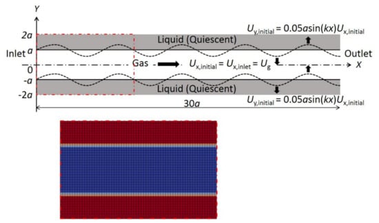
Figure 2.
Schematic of the computational fluid dynamics (CFD) analysis configuration, initial and boundary conditions, and mesh applied in the case of 300 ( direction) × 40 ( direction) cells.
When the base flow is disturbed by small perturbations, the initial perturbation is imposed on the direction velocity component as follows:
where 0.05.
The X direction velocity component is expressed as:
The linear theory neglects the gravity and gas viscosity ( 0) and represents the instability limit for inviscid liquid ( 0) as a relation between and [32]. In the present analysis, 0.1 ( 1 and 10), 1, 1, 2 (i.e., 0.5), and 1. The selection of these parameters results in unstable conditions, just as in the linear theory. The velocity gradients in areas other than the inlet and outlet of the gas phase region are all 0.
4. Results and Discussion
4.1. Consideration of the Validation Process
First of all, we considered a condition characterized by 1.2 million Cartesian cells (with 3000 and 400 cells in the and the direction, respectively) and 0. In Section 4.1 and Section 4.2, we did not take the IC method into account. The cell spacing was at a constant of 0.01 equivalent to 1/5, with an aspect ratio of 1, as shown in Figure 2. We intentionally selected the high-resolution mesh without mesh dependency for consideration of the validation process (The mesh convergence check is shown in the next section). We focused on the upper interface of the gas sheet in the CFD analysis. The disturbance amplitude was defined as , where exponentially increases with time due to the aerodynamic instability between the gas and liquid phases [39]. However, it was impossible to capture the amplitude growth by monitoring the liquid fraction distribution at a specific point due to the progressive wave; moreover, the difference between the highest (, crest) and the lowest (, trough) amplitude increased over time. Therefore, the wave amplitudes were averaged as follows:
We discussed the results, using as a validation criterion in the present study. The growth rate was compared with the theoretical value of 0.14, obtained by substituting the above values in Equation (9). is a good approximation of the growth rate in this study, focusing on the gradient of the growing amplitude.
Figure 3 shows the time variation of the upper disturbed interface of the gas sheet. Several periodic fluctuations became more evident alongside the amplitude growth, except for the amplitude near the inlet and the outlet affected by the boundary condition (Figure 3a). Thus, and were calculated for the region between 10 and 25. For the obtained the CFD result, we applied the three phases’ outlines of the evolution of the disturbance amplitude indicated by Jun et al. [40], who showed the growth rate of a single wavelength perturbation both with and without the magnetic field’s effects. Moreover, we specifically defined the phase condition in the present study, as shown in Figure 3b, as a superlinear phase from 0 to 8 (where the growth rate is dependent on the initial perturbation velocity), a linear phase from 8 to 21 (where the growth rate is consistent with the linear theory (error 10%)), and a sublinear phase after 21 (where a non-linear effect begins to dominate). The superlinear and sublinear phases are not consistent with the linear theory (error 10%). The CFD analysis was apparently performed validly, since the curve of the disturbance growth phases is qualitatively similar to the result obtained by Jun et al. [40].
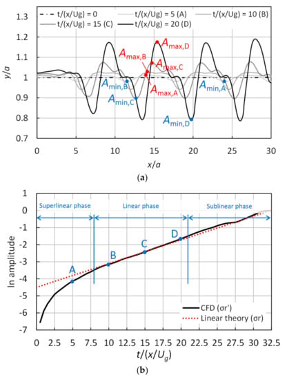
Figure 3.
Time variations of the disturbance on the gas sheet surface, in the case of 3000 ( direction) × 400 ( direction) cells, 0, and 2: (a) a visualization of the upper disturbed interface and (b) a natural logarithm of the disturbance amplitude.
Figure 4 illustrates the time variation of the disturbance amplitude for three different initial velocities in the Y direction, respectively represented by a multiplier of 0.5, 1, and 2 for the initial disturbance velocity in Figure 3. In all conditions, the linear phase began later, when the initial perturbation velocity was smaller; moreover, the natural logarithm of the disturbance amplitude agreed with the linear theory. That is to say, the growth velocity became constant approximately at a specific value. The sublinear phase began after 30 for a multiplier of 0.5 and after 16.5 for a multiplier of 2 when the error in the linear phase was under 10%, as mentioned above. Based on these results, the comparison with the linear theory was performed in the range between −3 and −2, where the growth behavior was unaffected by the initial velocity in the Y direction and the non-linear effect.
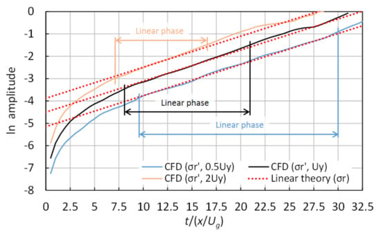
Figure 4.
Time variation of the natural logarithm of the disturbance amplitude for different initial velocities in the direction of the perturbations, in the case of 3000 ( direction) × 400 ( direction) cells, 0, and 2.
Figure 5 displays the time variation of the disturbance amplitude for different gas Weber numbers ( 1.7, 2, and 2.3) when changing only the surface tension ( 0.59, 0.5, and 0.44, respectively). is a dimensionless value defined as the ratio between surface tension and inertial force; it often controls the instability process, since the capillary forces resulting from the surface tension effect always tend to suppress instability [32]. The line’s gradient of the linear theory increases with . That intercept (at 0.5 and 1.7) was changed to fit the line’s gradient of the linear theory to the CFD result’s curve between −3 and −2. As a result, each intercept was −4.33 at 0.7 and −4.53 at 2.3 (−4.5 at 2). We confirmed a shorter linear phase and an faster transition to the sublinear phase in the case of 2.3 than in the other . The initiation timing of the linear phase is independent of and always constant, while it takes a shorter amount of time to reach the sublinear phase when increases, implying instability enhancement. Namely, the transition to the sublinear phase is sensitive to the Weber number. Figure 6 shows the time-averaged growth rate obtained with , indicating that the disagreement increases along with ; the reason behind this is probably related to the faster transition. The error was about 3.5% for 1.7, about 8% for 2 (used in the present analysis), and about 15.4% for 2.3.
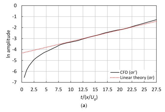
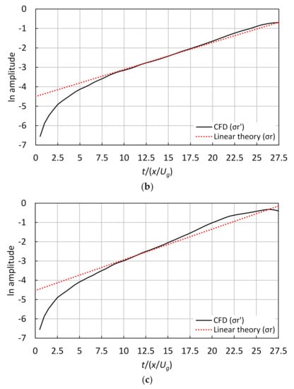
Figure 5.
Time variation of the natural logarithm of the disturbance amplitude for different gas Weber numbers (), in the case of 3000 ( direction) × 400 ( direction) cells and with 0: (a) 1.7, (b) 2, and (c) 2.3.
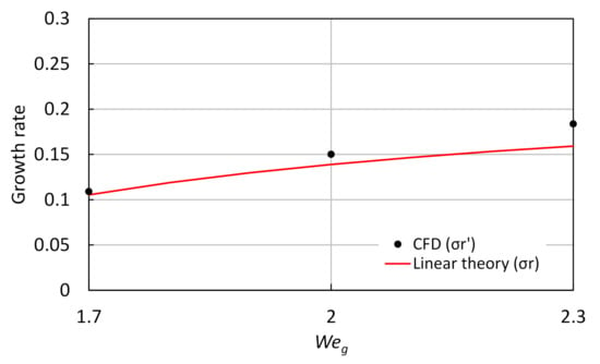
Figure 6.
Effect of the growth rate on the gas Weber number (), in the case of 3000 ( direction) × 400 ( direction) cells and with 0.
4.2. Effect of the Mesh Resolution
To create a simple image of the mesh resolution, we introduced the characteristic amplitude , which is the same size as (0.05), set at 5% of the gas sheet width. As a result, the mesh is represented by “5 cells/” (5 cells per amplitude) in terms of cell spacing per cell, which corresponds to 1.2 million Cartesian cells with 3000 and 400 cells in the and the direction, respectively. Table 1 lists the analysis cases by the number of cells. The aspect ratio of 1 is constant, as it was with the previous section. We investigated the effect of the numerical cell size at 2 and 0; the minimum number of cells was 0.35 cells/ because it was impossible to capture the interface with larger cells, since they completely buried the grown disturbance.

Table 1.
Analysis cases.
Figure 7 shows the time-averaged growth rate for each mesh resolution tested (Table 1). Checking the mesh convergence can help to investigate the mesh resolution’s effect and reduce the analysis cases. The growth rate decreased and approximated the linear theory at 2.5 cells/ and higher. In contrast, after the growth rate improved slightly at 1 cells/, it deviated significantly from the linear theory below 1 cell/, and calculation accuracy worsened. That is to say, the mesh convergence was confirmed at 1 cell/, and the effect of the cell size caused by interface dispersion seemed to be below 1 cell/. The mesh sized at 0.35 cells/ was not used for the following considerations because it have might impaired the quality of the growth rate results, while the mesh sized at 0.5 cells/ was utilized to investigate the effect of the IC method under large numerical diffusion, as a reference.
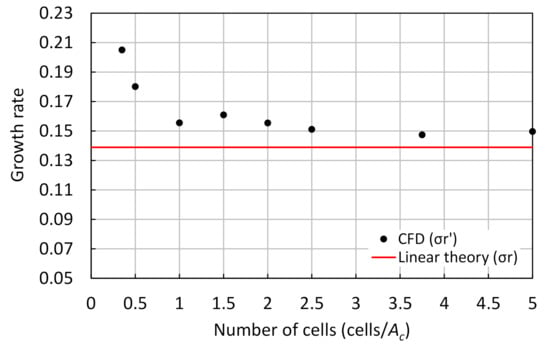
Figure 7.
Effect of the growth rate on the number of cells, for 0 and 2.
Figure 8 illustrates the time variation of the gas sheet disturbance for 0.5, 1.5, and 2.5 cells/, along with the effect of the interface dispersion at a lower mesh resolution. The amplitude increased after 10 along with the number of cells, and its fluctuation and periodicity changed. Moreover, the boundary condition’s effect in the inlet intensified near 5 to 6 with the decrease in the number of cells at 20. In particular, the negative amplitude troughs did not increase much, except for the first trough near 9 at 0.5 cells/. The results for 1.5 and 2.5 cells/ agreed well with the linear theory, unlike those at 0.5 cells/ before 18. These results imply that amplitude growth cannot be accurately evaluated in a large cell because the influence of numerical diffusion by mesh resolution is too large. At 0.5 cells/, the growing interface was not resolved with the cell as of 5; thus, differences began to appear in the graph’s curve (Figure 8b). This curve of 0.5 cells/ reached the line of the linear theory at 18.
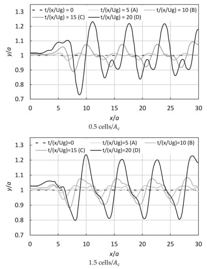
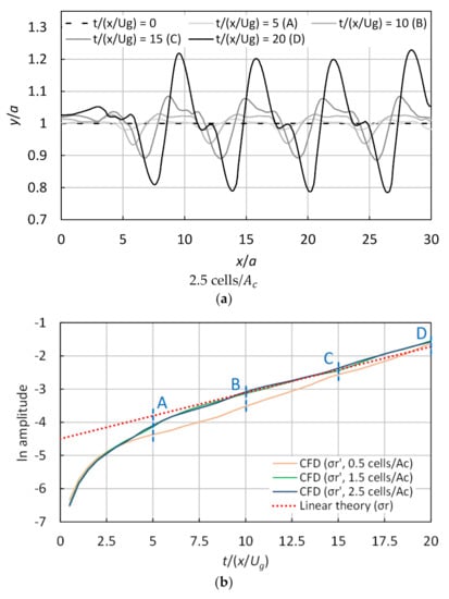
Figure 8.
Time variation of the disturbance on the gas sheet surface for different numbers of cells (0.5, 1.5, and 2.5 cells/): (a) a visualization of the upper disturbed interface, for 0 and 2, and (b) a natural logarithm of the disturbance amplitude.
4.3. Effect of the IC Method
Figure 9 shows the liquid fraction near the interface for different IC coefficients (0, 0.5, 1, and 2) at 0.5, 1.5, and 2.5 cells/ and after 15 for 15. The width marked with arrows in the figure shows the cell spacing. The IC coefficient influenced the gradient of the liquid fraction distribution near the surface, showing increased improvement at 0.5 cells/. However, the effect of the number of cells was larger than that of . Furthermore, the distribution’s gradient did not always change at the same position and changed by only 2 when the IC coefficient was varied at 2.5 cells/; this tendency was also confirmed at 5 cells/, but this result is not reported here. This means that the correlation between IC coefficient and cell size apparently had some effect, and 2 had a different effect from the other IC coefficients under small numerical diffusion by mesh resolution.
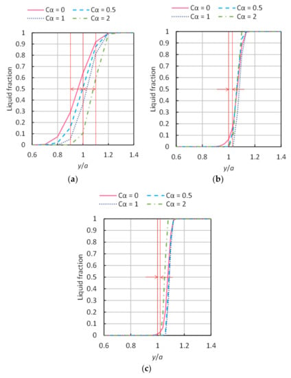
Figure 9.
Liquid fractions near the upper disturbed interface for different interface compression (IC) coefficients () at 15 for 15 ( 2): (a) 0.5 cells/, (b) 1.5 cells/, and (c) 2.5 cells/.
Figure 10 displays the plots of the disturbance amplitudes for different numbers of cells (0.5, 1.5, and 2.5 cells/) and , showing the larger effects of the IC method while decreasing the mesh resolution; larger values increased the growth rate quicker, although it then tended to overshoot. The IC method worked effectively for 0.5 and 0.75 at 0.5 cells/. Figure 11 illustrates the growth rate as a function of the IC coefficient for different numbers of cells, revealing two things: (1) affected the growth rate when ranging between 0.25 and 0.5 inclusive at 1.5 cells/ and between 0.25 and 0.75 inclusive at 2.5 cells/; (2) at 0.5 cells/, the growth rate approached that of the linear theory with increasing . For (1), 0 0.75 was reasonable at 1 cell/ from conservative judgment, and the growth rate closest to the linear theory was at 0.25 for both mesh cases (1.5 and 2.5 cells/). Kawasaki et al. [19] have reported that 0 0.5 leads to suitable numerical results for the simulation of collisions between the bore and a structure; their results are similar to the present result, which indicates that 0 0.75 is an appropriate range to resolve their problems regarding the intensity of the IC coefficient. However, 2, at 1.5 and 2.5 cells/ seemed an inappropriate value because the differences between the CFD and the linear theory were wider. This large difference can be confirmed not only in Figure 11 but also in the gradients of the curves at 2 in Figure 10. As for (2), it means that the IC method worked well, especially on the dispersion interface. 2 at 0.5 cells/ (indicating the growth rate closest to the linear theory) reduced the error from 29% (without the IC method) to 6%, as shown in Figure 11. The curve’s gradient for 2 at 0.5 cells/ did not agree with the line of the linear theory in Figure 10 due to the calculation accuracy problem caused by the mesh resolution. Nevertheless, that curve’s gradient fit the line’s gradient of the linear theory, and the negative diffusion worked well.
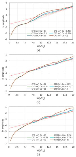
Figure 10.
Time variation of the natural logarithm of the disturbance amplitude for different interface compression (IC) coefficients (), at 2: (a) 0.5 cells/, (b) 1.5 cells/, and (c) 2.5 cells/.
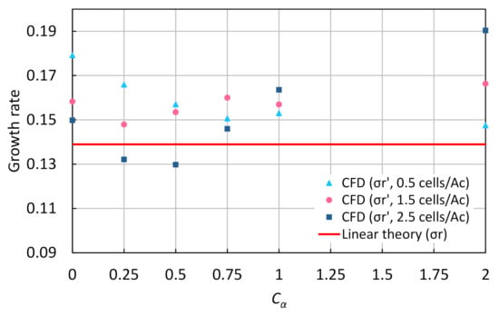
Figure 11.
Effect of the interface compression (IC) coefficient () on the growth rate, at 2.
5. Conclusions
This study focused on validating the VOF method using the IC method for two-phase flow CFD analysis. The 2D inviscid flow of a plane gas sheet in a quiescent liquid phase was analyzed. An initial perturbation in the sine waveform was imposed, and the amplitude growth rates were compared with those of the linear theory. The following parameters were investigated: perturbation wavelength, gas Weber number, mesh resolution, and IC coefficient. The disturbance growth rates were consistent with the linear theory when the mesh resolution was sufficient (at 0), except for periods influenced by the initial disturbance velocity and the non-linear effect. This confirmed the appropriateness of the validation process adopted. Moreover, the mesh convergence was confirmed by comparing eight analysis cases of different numerical cells to investigate the mesh resolution effect and narrow down the analysis cases; the mesh resolution’s influence was confirmed below 1 cell/ because of the interface dispersion in larger cells. IC coefficients between 0 and 0.75 indicated the valid results at 1 cell/ and higher. Below 1 cell/, wherein the interface dispersion is large, 2 improved the error, compared with the case without the IC method. Therefore, the IC method can effectively suppress the interface dispersions that result from numerical diffusion. However, the IC coefficient should be selected appropriately, because the negative diffusion increases with the IC coefficient’s increase. We believe that the proposed validation process is suitable to decide the IC coefficient while providing less error. This knowledge could be usefully applied in a wide two-phase field of the CFD analysis.
Author Contributions
Conceptualization, Y.O. and T.Y.; methodology, M.I. and Y.H.; software, Y.O. and M.I.; validation, Y.O.; formal analysis, Y.O.; writing—original draft preparation, Y.O.; writing—review and editing, Y.O., T.Y., M.I. and Y.H.; visualization, Y.O.; supervision, T.Y. All authors have read and agreed to the published version of the manuscript.
Funding
This research received no external funding.
Conflicts of Interest
The authors declare no conflict of interest.
References
- Höhne, T.; Krepper, E.; Rohde, U. Application of CFD codes in nuclear reactor safety analysis. Sci. Technol. Nucl. Install. 2010, 2010, 198758. [Google Scholar] [CrossRef]
- Use of Computational Fluid Dynamics Codes for Safety Analysis of Nuclear Reactor Systems. Available online: https://inis.iaea.org/collection/NCLCollectionStore/_Public/36/103/36103090.pdf?r=1 (accessed on 8 February 2021).
- Mahaffy, J.; Chung, B.; Dubois, F.; Ducros, F.; Graffard, E.; Heitsch, M.; Henriksson, M.; Komen, E.; Moretti, F.; Morii, T.; et al. Best Practice Guidelines for the Use of CFD in Nuclear Reactor Safety Application—Revision; NEA/CSNI/R(2014)11; Organisation for Economic Co-operation and Development (OECD): Paris, France, 2015. [Google Scholar]
- Bestion, D. The difficult challenge of a two-phase CFD modelling for all flow regimes. Nucl. Eng. Des. 2014, 279, 116–125. [Google Scholar] [CrossRef]
- Hirt, C.W.; Nichols, B.D. Volume of fluid (VOF) method for the Dynamics of Free Boundaries. J. Comput. Phys. 1981, 39, 201–225. [Google Scholar] [CrossRef]
- Sussman, M.; Smereka, P.; Osher, S. A Level Set Approach for Computing Solutions to Incompressible Two-Phase Flow. J. Comput. Phys. 1994, 114, 146–159. [Google Scholar] [CrossRef]
- Tryggvason, G.; Bunner, B.; Esmaeeli, A.; Juric, D.; Al-Rawahi, N.; Tauber, W.; Han, J.; Nas, S.; Jan, Y.-J. A Front-Tracking Method for the Computations of Multiphase Flow. J. Comput. Phys. 2001, 169, 708–759. [Google Scholar] [CrossRef]
- Ohta, M.; Sakai, M.; Shimada, N.; Homma, S.; Matsukuma, Y. Numerical Simulation of Multi-Phase Flows; Maruzen Publishing Co., Ltd.: Tokyo, Japan, 2015; pp. 31–63. (In Japanese) [Google Scholar]
- Noh, W.F.; Woodward, P. SLIC (simple line interface calculation). In Proceedings of the 5th International Conference on Numerical Methods in Fluid Dynamics, Enschede, The Netherlands, 28 June–2 July 1976; Springer: Berlin/Heidelberg, Germany, 1976; pp. 330–340. Available online: https://link.springer.com/chapter/10.1007/3-540-08004-X_336 (accessed on 28 January 2021).
- Youngs, D.L. Time-dependent multi-material flow with large fluid distortion. In Numerical Methods for Fluid Dynamics; Morton, K.W., Baines, M.J., Eds.; Academic Press: London, UK, 1982; pp. 273–285. [Google Scholar]
- Sussman, M.; Puckett, E.G. A coupled level set and volume-of-fluid method for computing 3D and axisymmetric incompressible two-phase flows. J. Comput. Phys. 2000, 162, 301–337. [Google Scholar] [CrossRef]
- Yokoi, K. Efficient implementation of THINC scheme: A simple and practical smoothed VOF algorithm. J. Comput. Phys. 2007, 226, 1985–2002. [Google Scholar] [CrossRef]
- Ubbink, O.; Issa, R.I. A method for capturing sharp fluid interfaces on arbitrary meshes. J. Comput. Phys. 1999, 153, 26–50. [Google Scholar] [CrossRef]
- Wacławczyk, T.; Koronowicz, T. Comparison of CICSAM and HRIC high-resolution schemes for interface capturing. J. Theor. Appl. Mech. 2008, 46, 325–345. [Google Scholar]
- Weller, H.G. A New Approach to VOF-Based Interface Capturing Methods for Incompressible, Compressible and Cavitating Flow; OpenCFD Technical Report TR/HGW/07; OpenCFD: Salfords, UK, 2006. [Google Scholar]
- Wardle, K.E.; Weller, H.G. Hybrid multiphase CFD solver for coupled dispersed/segregated flows in liquid-liquid extraction. Int. J. Chem. Eng. 2013, 2013, 128936. [Google Scholar] [CrossRef]
- Deshpande, S.S.; Anumolu, L.; Trujillo, M.F. Evaluating the performance of the two-phase flow solver interFoam. Comput. Sci. Discov. 2012, 5, 014016. [Google Scholar] [CrossRef]
- Deshpande, S.S.; Trujillo, M.F.; Wu, X.; Chahine, G. Computational and experimental characterization of a liquid jet plunging into a quiescent pool at shallow inclination. Int. J. Heat Fluid Flow 2012, 34, 1–14. [Google Scholar] [CrossRef]
- Kawasaki, K.; Matsuura, S.; Sakatani, T. Validation of free surface analysis method in three-dimensional computational fluid dynamics tool “OpenFOAM”. J. Jpn. Soc. Civ. Eng. B3 2013, 69, I_748–I_753. (In Japanese) [Google Scholar]
- Piro, D.J.; Maki, K.J. An Adaptive Interface Compression Method for Water Entry and Exit; Technical Report 2013-350; Department of Naval Architecture and Marine Engineering, University of Michigan: Ann Arbor, MI, USA, 2013; Available online: http://deepblue.lib.umich.edu/handle/2027.42/97021 (accessed on 5 November 2020).
- Lafaurie, B.; Nardone, C.; Scardovelli, R.; Zaleski, S.; Zanetti, G. Modelling merging and fragmentation in multiphase flows with SURFER. J. Comput. Phys. 1994, 113, 134–147. [Google Scholar] [CrossRef]
- Gerlach, D.; Tomar, G.; Biswas, G.; Durst, F. Comparison of volume-of-fluid methods for surface tension-dominant two-phase flows. Int. J. Heat Mass Transf. 2006, 49, 740–754. [Google Scholar] [CrossRef]
- Hoang, D.A.; van Steijn, V.; Portela, L.M.; Kreutzer, M.T.; Kleijn, C.R. Benchmark numerical simulations of segmented two-phase flows in microchannels using the Volume of Fluid method. Comput. Fluids 2013, 86, 28–36. [Google Scholar] [CrossRef]
- Shonibare, O.Y.; Wardle, K.E. Numerical investigation of vertical plunging jet using a hybrid multifluid-VOF multiphase CFD solver. Int. J. Chem. Eng. 2015, 2015, 925639. [Google Scholar] [CrossRef]
- Anez, J.; Demoulin, F.; Hecht, N.; Reveillon, J. A general purpose LES model for atomization. In Proceedings of the 27th European Conference on Liquid Atomization and Spray Systems (ILASS-Europe 2016), Brighton, UK, 4–7 September 2016; pp. 1–7. Available online: https://hal.archives-ouvertes.fr/hal-02128542 (accessed on 5 November 2020).
- Lee, H.; Rhee, S.H. A dynamic interface compression method for VOF simulations of high-speed planing watercraft. J. Mech. Sci. Technol. 2015, 29, 1849–1857. [Google Scholar] [CrossRef]
- Matsumoto, K. Optimization of the Fluid Operating Conditions on the Filling Production Process of Liquid Foods. Ph.D. Thesis, Tokushima University, Tokushima, Japan, 2017. (In Japanese). [Google Scholar]
- Fleau, S.; Mimouni, S.; Mérigoux, N.; Vincent, S. Simulations of two-phase flows with a multifield approach. In Proceedings of the 6th International Symposium on Advances in Computational Heat Transfer (CHT-15), Piscataway, NJ, USA, 25–29 May 2015; pp. 1–17. Available online: https://hal-upec-upem.archives-ouvertes.fr/hal-01172289 (accessed on 5 November 2020).
- Bartosiewicz, Y.; Laviéille, J.; Seynhaeve, J.-M. A first assessment of the NEPTUNE_CFD code: Instabilities in a stratified flow comparison between the VOF method and a two-field approach. Int. J. Heat Fluid Flow 2008, 29, 460–478. [Google Scholar] [CrossRef]
- Štrubelj, L.; Tiselj, I. CFD simulation of Kelvin-Helmholtz instability. In Proceedings of the International Conference Nuclear Energy for New Europe 2005, Bled, Slovenia, 5–8 September 2005; pp. 002.1–002.10. Available online: https://inis.iaea.org/search/search.aspx?orig_q=RN:37104700 (accessed on 5 November 2020).
- Štrubelj, L.; Tiselj, I. Numerical simulations of basic interfacial instabilities with incompressible two-fluid model. Nucl. Eng. Des. 2011, 241, 1018–1023. [Google Scholar] [CrossRef]
- Li, X.; Bhunia, A. Temporal instability of plane gas sheets in a viscous liquid medium. Phys. Fluids 1996, 8, 103–111. [Google Scholar] [CrossRef]
- The OpenFOAM Foundation. OpenFOAM User Guide Version 2.3.0. Available online: https://openfoam.org/version/2-3-0/ (accessed on 8 February 2021).
- Issa, R.I. Solution of the implicitly discretised fluid flow equations by operator-splitting. J. Comput. Phys. 1986, 62, 40–65. [Google Scholar] [CrossRef]
- Caretto, L.S.; Gosman, A.D.; Patankar, S.V.; Spalding, D.B. Two calculation procedures for steady, three-dimensional flows with recirculation. In Proceedings of the Third International Conference on Numerical Methods in Fluid Mechanics, Paris, France, 3–7 July 1972; Springer: Berlin/Heidelberg, Germany, 1972; pp. 60–68. [Google Scholar]
- Rusche, H. Computational Fluid Dynamics of Dispersed Two-Phase Flows at High Phase Fractions. Ph.D. Thesis, Imperial College of Science, Technology and Medicine, London, UK, 2002. [Google Scholar]
- Weller, H.G. Derivation, Modelling and Solution of the Conditionally Averaged Two-Phase Flow Equations; OpenCFD Technical Report TR/HGW/02; OpenCFD: Salfords, UK, 2005. [Google Scholar]
- Giussani, F.; Montorfano, A.; Piscaglia, F.; Onorati, A.; Helie, J.; Aithal, S.M. Dynamic VOF modelling of the internal flow in GDI fuel injectors. Energy Procedia 2016, 101, 574–581. [Google Scholar] [CrossRef]
- Li, X.; Tankin, R.S. On the temporal instability of a two-dimensional viscous liquid sheet. J. Fluid Mech. 1991, 226, 425–443. [Google Scholar] [CrossRef]
- Jun, B.-I.; Norman, M.L.; Stone, J.M. A numerical study of Rayleigh-Taylor instability in magnetic fluids. Astrophys. J. 1995, 453, 332–349. [Google Scholar] [CrossRef]
Publisher’s Note: MDPI stays neutral with regard to jurisdictional claims in published maps and institutional affiliations. |
© 2021 by the authors. Licensee MDPI, Basel, Switzerland. This article is an open access article distributed under the terms and conditions of the Creative Commons Attribution (CC BY) license (http://creativecommons.org/licenses/by/4.0/).