Article

Impact of High Inertia Particles on the Shock Layer and Heat Transfer in a Heterogeneous Supersonic Flow around a Blunt Body

Moscow Aviation Institute, National Research University, Volokolamskoye sh. 4, 125993 Moscow, Russia
*
Author to whom correspondence should be addressed.
Fluids 2021, 6(11), 406; https://doi.org/10.3390/fluids6110406
Submission received: 8 October 2021 / Revised: 3 November 2021 / Accepted: 4 November 2021 / Published: 9 November 2021
(This article belongs to the Special Issue High Speed Flows)

Abstract

:
One of the most important and complex effects associated with the presence of particles in the flow is the gas-dynamic interaction of particles with the shock layer. Of particular interest is the intensification of heat transfer by high inertia particles rebounding from the surface or by the products of erosion destruction, which reach the front of the bow shock wave and violate the gas-dynamic structure of the flow. In this case, according to experimental data, the increase in heat fluxes is much greater than it could be predicted based on the combined action of the kinetic energy of particles and a high-speed flow. The problem is related to the destruction of the flow structure. In this paper, the problem is studied with numerical simulation. We show that the key role in the intensification of heat transfer is played by the formation of an impact jet flowing onto the surface. An area of increased pressure and heat flux is formed in the zone of action of the impact jet. This effect is maintained over time by the successive action of particles.

1. Introduction

Flows with suspended solid or liquid particles (heterogeneous flows) are present in many applications. Heterogenous flows are used in some technologies and structures for transport and energy purposes, such as the pneumatic conveying of bulk materials, the jet-abrasive treatment of machine parts, and for rocket engines running on metalized fuel. In many devices, particles enter the fluid flow against the will of the developers. For example, we can cite steam and gas turbine installations and gas-dynamic research stands, where it is problematic to get rid of particles completely despite the use of powerful filtration systems. In the atmosphere of the Earth and other planets, there is dust or clouds containing liquid (rain) or solid (snow, hail) particles. Therefore, one of the important problems of high-speed flight in the lower atmosphere is overcoming areas with different dispersion formations.
Various aspects of heterogeneous flows and their interaction with bodies are considered in a number of monographs and reviews [1,2,3,4,5,6]. From the point of view of the effect of a heterogeneous flow on an obstacle, the following main mechanisms can be distinguished: shock action, leading to additional heating and, possibly, erosion of the surface, enhancement of the convective heat transfer, and the radiative heat transfer between a dispersed phase and the body surface. It should be noted that these mechanisms are interrelated. The intensity of the erosion depends on the temperature of the material, which is formed under the action of the convective and radiative heat transfer. On the other hand, the release of the erosion products into the flow and changes in the body’s shape due to erosion affect the heat transfer processes [2,7].
In this work, we focus on the issues of convective heat transfer enhancement. A number of new effects complicate the convective heat transfer in a heterogeneous supersonic flow around bodies compared to the traditional dust-free gas flow. Among them are the intensification of heat transfer due to an interphase energy exchange in the boundary layer, the acceleration of the laminar-turbulent transition, and the intensification of heat transfer due to the formation of craters on the exposed surface. The issues of heat transfer intensification in heterogeneous flows around bodies are considered in [8,9,10,11,12,13] for various inertial properties of particles and modes of particle deposition on the surface. Heat transfer enhancement caused by craters on the surface is discussed in [14,15].
Of particular interest is the intensification of heat transfer by high inertia particles rebounding from the surface or by the products of erosion destruction, which reach the front of the bow shock wave and violate the gas-dynamic structure of the flow. In this case, according to the experimental data [16,17,18,19,20], the increase in heat fluxes is much greater than it could be predicted based on the combined action of the kinetic energy flux of particles and the high-velocity flow. Thus, it is impossible to explain the increase in the model heating by the complete transition of the kinetic energy of particles into thermal energy. The problem is related to the destruction of the flow structure. This case is challenging for the numerical simulation due to the significant difference in scales between the body and particles.
In our previous work, we developed algorithms for the numerical simulation of a supersonic flow around bodies, taking into account the gas-dynamic interaction of the shock layer with a high inertia particle [21,22,23,24]. Distinctive features of our technique are the use of high-resolution adaptive sliding Cartesian grids, the immersed boundary ghost cell method for boundary conditions treatment, and the parallelization of computations on GPUs.
We used the developed computer model to carry out a series of computational experiments aimed at identifying characteristic shockwave and vortex structures formed when a single particle reflected from the surface passes through the bow shock wave [21,22]. Variants of flow around a cylinder with spherical bluntness and a flat end have been investigated. Detailed spatio-temporal pictures of the gas-dynamic interaction of the disturbed region in the vicinity of the particle with the macroscopic flow in the shock layer and the bow shock were obtained. It is shown that the shock wave and vortex flow structures are to a certain extent similar to those observed in the flow around spiked bodies [25,26]. Furthermore, a study of the oscillatory flow and heat transfer regimes induced by the gas-dynamic interaction of a high inertia particle with the shock layer was carried out. The shockwave structures and oscillation frequencies obtained through numerical simulation [23] agree well with experimental data [17].
The numerical simulation [24] showed significant growth of the heat flux even under the gas-dynamic action of a single particle. However, it lasts for a relatively short period and does not lead to overall heat transfer intensification. The next question is whether several particles’ subsequent actions can keep the high heat flux level over time. This effect is the subject of the present article.

2. Model and Methods

In our previous work [21,22,23,24], we considered the gas-dynamic interaction of a single particle with a shock layer in the flow around an axisymmetric body. In this case, the particle moved strictly along the axis of symmetry, which made it possible to solve the problem in a two-dimensional formulation. This is of principal importance since modeling the gas-dynamic interaction requires a high grid resolution near a moving particle. Even in a two-dimensional version, solving the problem requires enormous computational costs. The deviation of a particle from the axis of symmetry violates the axisymmetric structure of the flow and requires three-dimensional modeling. Considering that in this work we studied the collective action of a group of particles on the shock layer, we were forced to simplify the problem by considering the process in a two-dimensional formulation (plane flow). Of course, it was difficult to talk about the quantitative agreement between the results and experimental data with this approach. However, it was possible to trace the qualitative features of the group effect of particles on the flow structure and heat transfer.
Thus, a supersonic flow around a flat, blunt body was considered. The flow was assumed to be laminar. Particles successively left the body surface towards the flow. Figure 1 represents the computational domain.
The flow of a viscous compressible gas is described by a system of two-dimensional unsteady Navier–Stokes equations:
q t + F ( q ) x + G ( q ) y = F v ( q ) x + G v ( q ) y q = ( ρ ρ u ρ v ρ e ) ,   F = ( ρ u ρ u 2 + p ρ u v ρ u H ) ,   G = ( ρ v ρ u v ρ v 2 + p ρ v H ) F v = ( 0 τ x x τ x y τ x x u + τ x y v q x ) ,   G v = ( 0 τ y x τ y y τ y x u + τ y y v q y )
where t is time, ρ is the gas density, p is pressure, T is temperature, u and v are gas velocity components along the x and y axes, γ is the specific heat ratio, e = p ρ ( γ 1 ) + 1 2 ( u 2 + v 2 ) —total specific energy, H = e + p ρ —total enthalpy, and qx and qy are heat flux components.
The equation of the state connecting the gas parameters has the form: p = ρ R T .
The viscous stress tensor components are: τ x x = 2 3 μ ( 2 u x v y ) , τ y y = 2 3 μ ( 2 v y u x ) , τ x y = τ y x = μ ( u y + v x ) .
The viscosity coefficient is calculated using Sutherland’s formula, and the thermal conductivity coefficient is defined from the viscosity coefficient and the Prandtl number, which is supposed to be constant and equal to 0.72.
To complete the problem formulation, we set the conditions on the boundaries of the computational domain.
The conditions at the input boundary are the following:
ρ n = 0 ,   u = u ,   v = 0 ,   p n = 0 ,
where u is the free flow velocity and n —normal vector to the boundary.
The conditions at the output boundary are:
ρ n = 0 ,   u n = 0 ,   v n = 0 ,   p n = 0
On the cylinder surface, we set standard boundary conditions:
p n = 0 ,   u = 0 ,   v = 0 ,   T = T w  
where Tw is the surface temperature.
The same conditions were set at the particle boundaries.
At the initial moment, the first particle started from the body surface against the incident flow along the normal to the surface; the gas flow pattern at this moment corresponded to the stationary regime of the transverse flow around a circular cylinder. Further, other particles were sequentially launched from close by but at different points on the surface.
The motion of the particles in a gaseous medium is described by the classical dynamic equations:
d r p d t = v p ,   m p d v p d t = f D
where m p   r p , v p are the particle mass, position vector, and velocity, and f D is the drag force.
In this work, the drag force was calculated by integrating the gas pressure distribution over the particle surface. A comparison with experimental data [21] showed that, although this approach ignored the friction force, it allowed a much more accurate description of the particle dynamics in comparison with the known criterion dependencies for the drag coefficient.
Thus, the Navier–Stokes equations were solved in a complex region with curvilinear, movable boundaries determined by the motion of particles. This significantly distinguishes this approach from the traditional Euler–Lagrangian approach, where the interphase interaction is taken into account in additional exchange terms.
The Navier–Stokes equations were solved using the TVD—monotonized second-order scheme in combination with the AUSM + (Advection Upstream Splitting Method Plus) method for calculating fluxes through the faces of the computational cell [27,28,29]. Discretization of the Navier–Stokes equations was performed on a rectangular adaptive grid. The boundary conditions were approximated according to the immersed boundary ghost cell method [7,30,31,32].
We used sliding grids [33,34,35] to take into consideration the motion of particles. Along with the primary coordinate system associated with the cylinder, local coordinate systems were introduced that were attached to each moving particle. The gas flow around each object was calculated on a separate “local” computational grid in its coordinate system. The coordinate system associated with the cylinder was considered to be stationary, its computational grid is hereinafter referred to as “primary”, and the conditions at its input boundary were determined by the parameters of the incident flow. The boundary conditions for the local grid attached to the particle were determined by the gas parameters obtained on the primary grid depending on the particle position and velocity. At each step of the calculation on the primary grid, the gas parameters in the outer cells of the moving grid were calculated using bilinear interpolation since the centers of the cells of the two grids were usually displaced relative to each other. The gas-dynamic equations were solved in the local coordinate system of a moving particle. Its displacement was calculated, and the obtained gas parameters in the inner region were transferred to the primary grid using the inverse transformation. Figure 2 schematically shows the position of the local computational grid relative to the main one at different points in time.

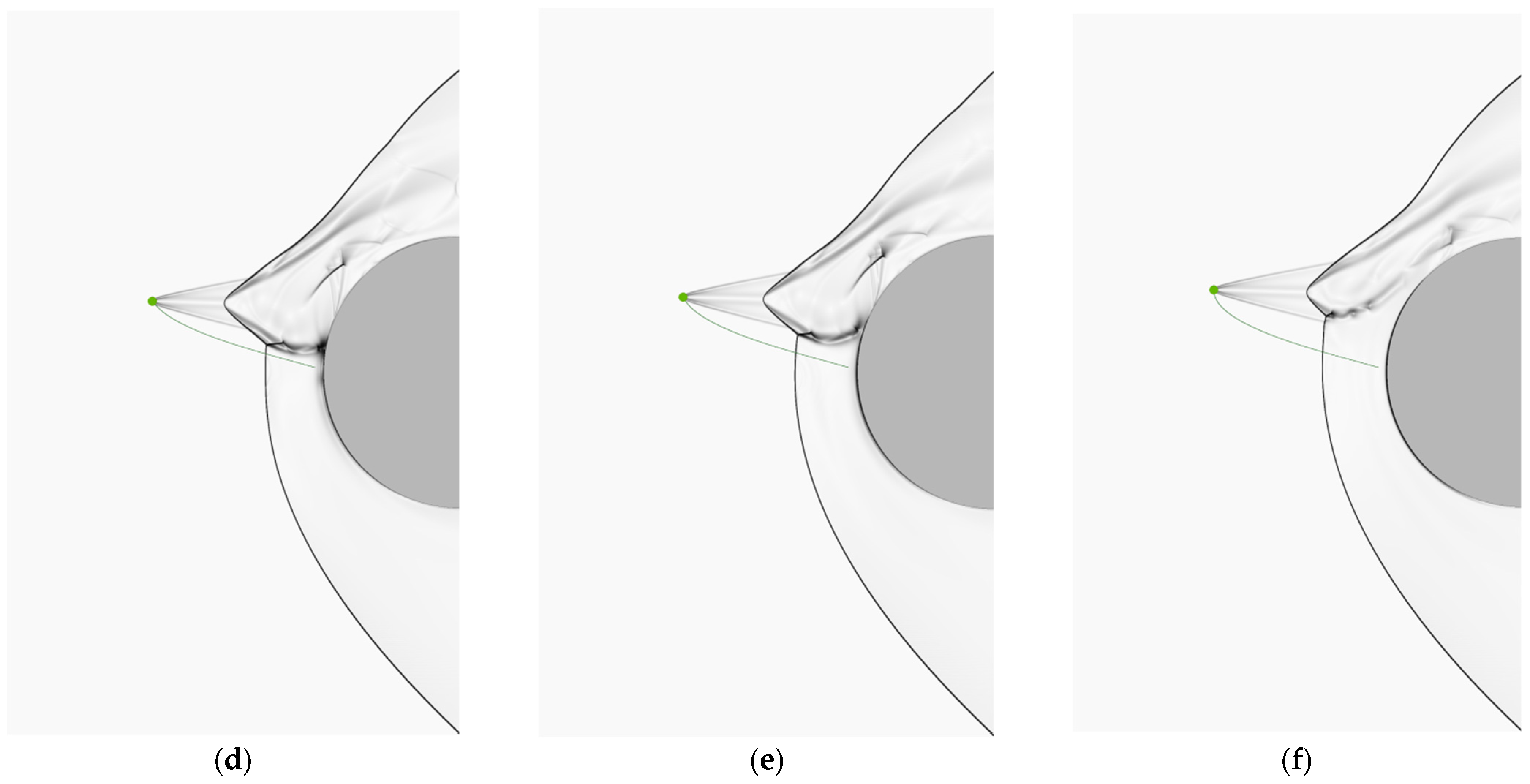
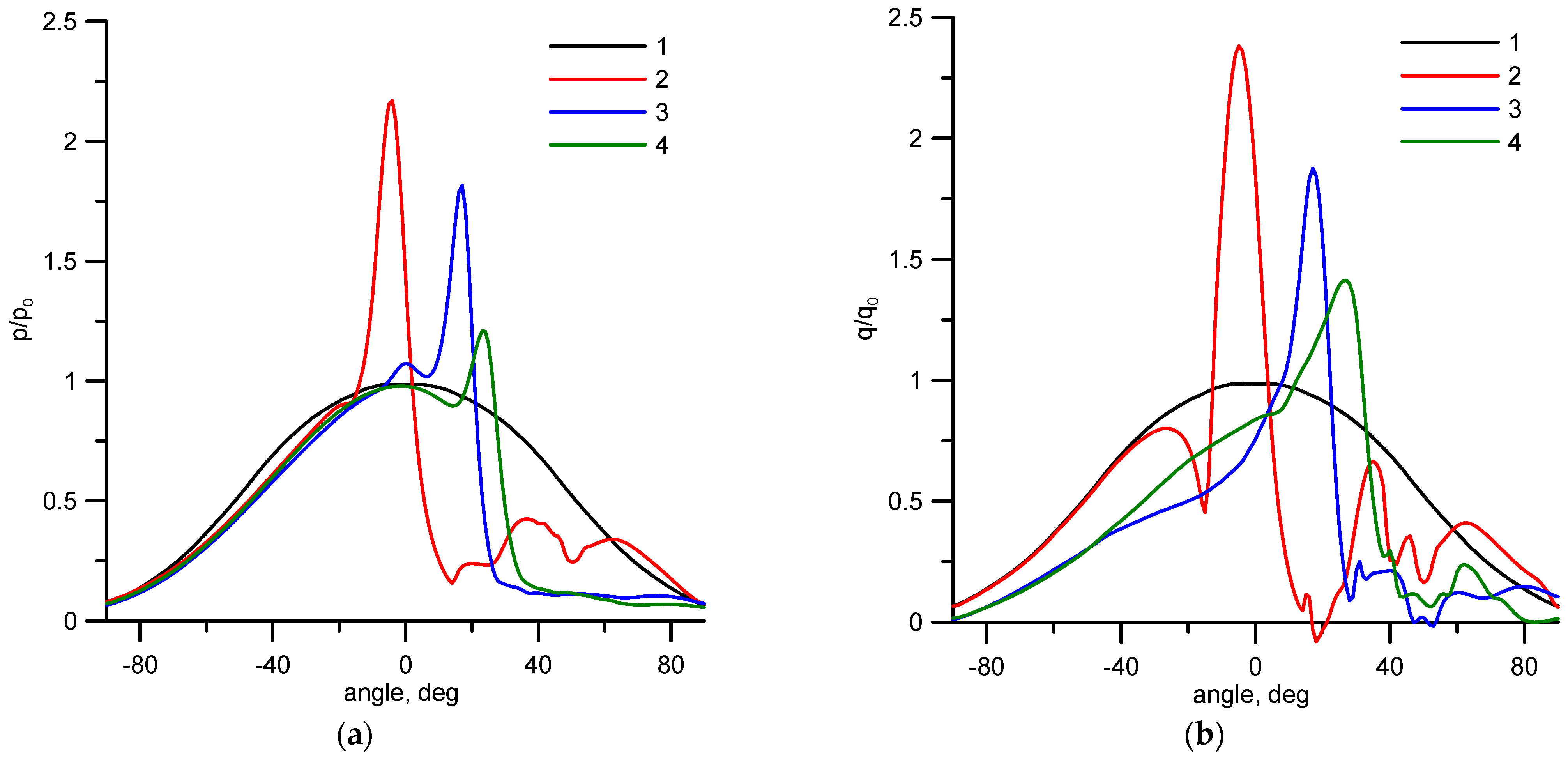
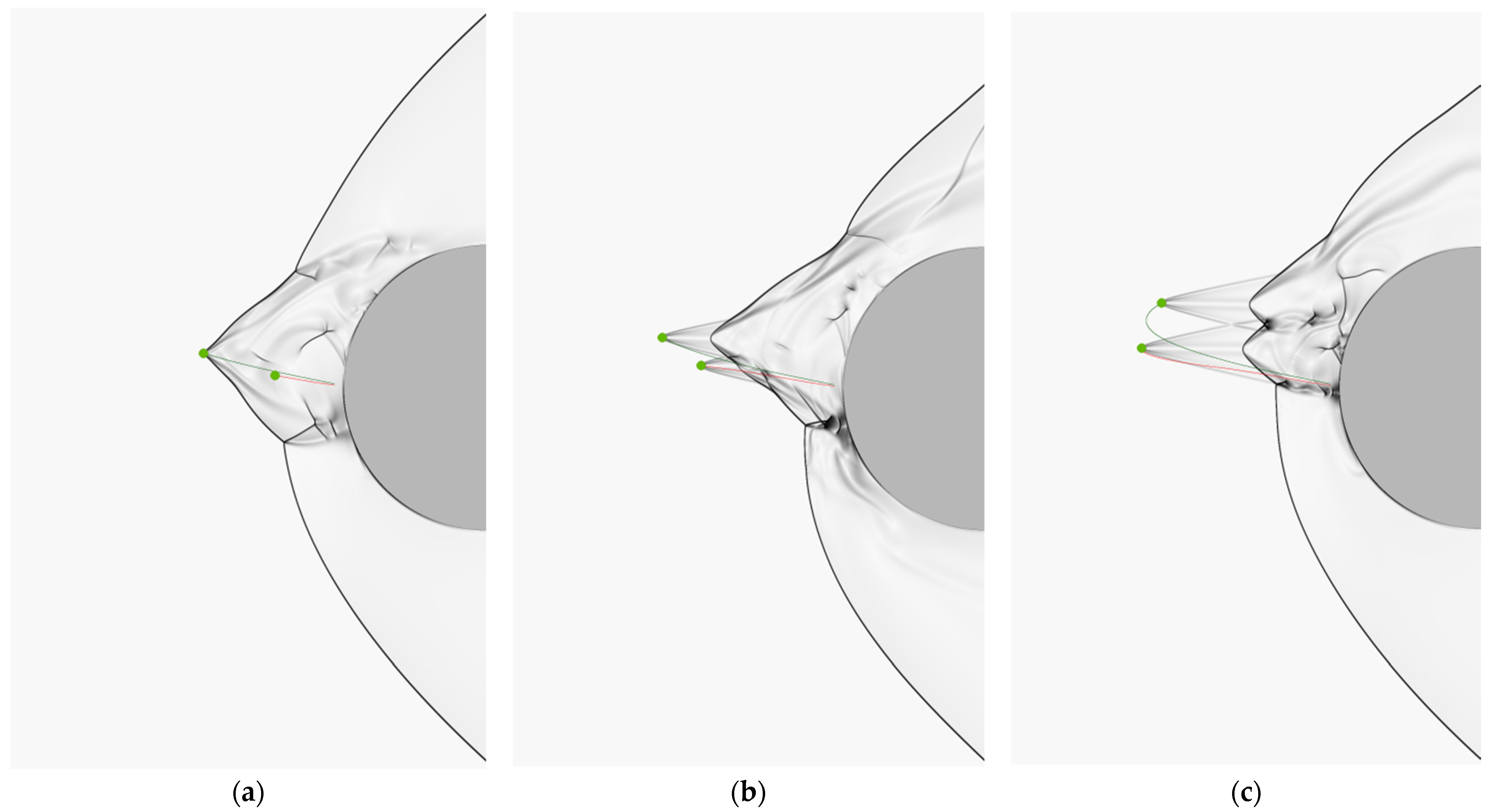
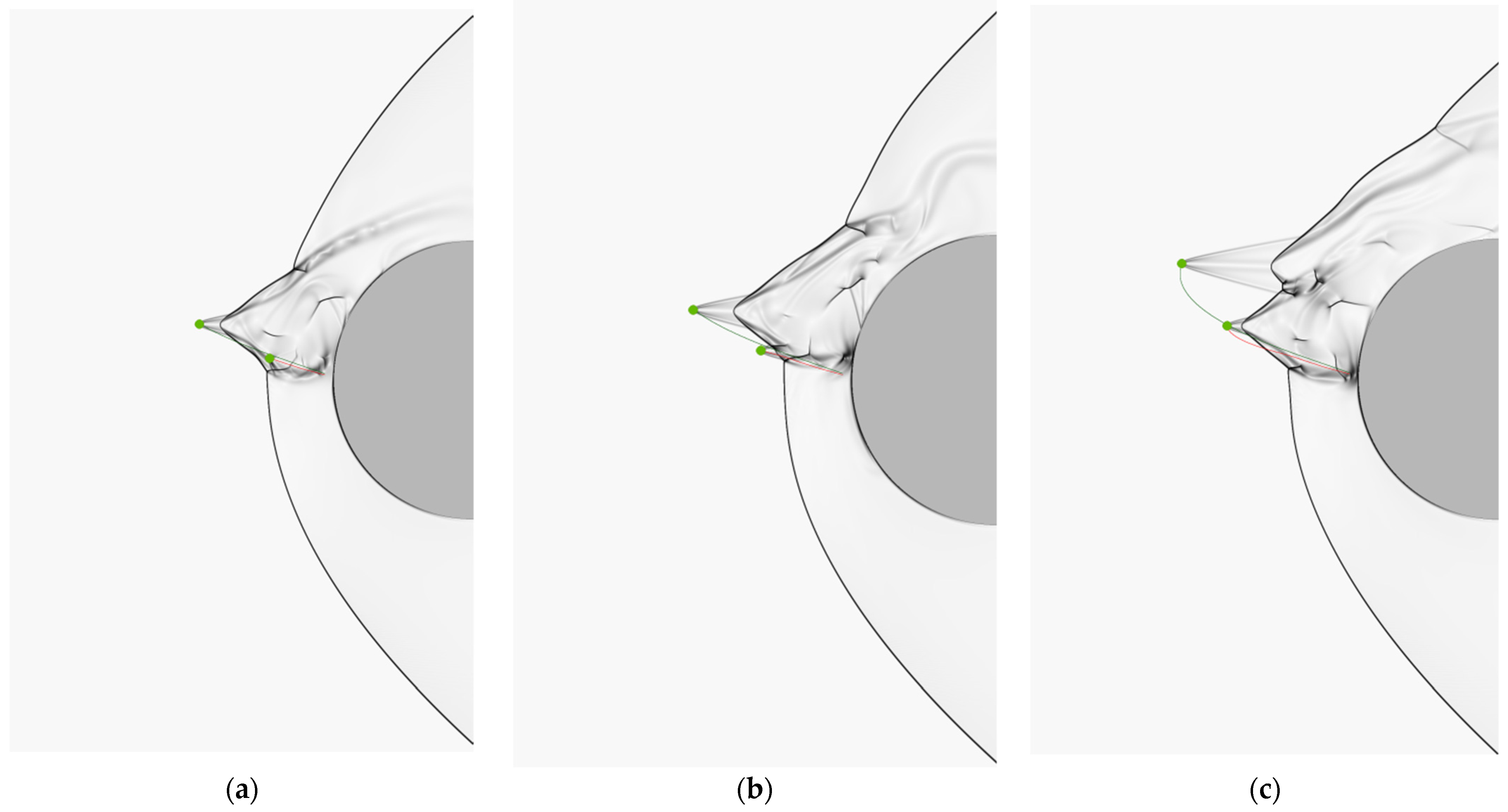
3. Results and Discussion

In computational experiments, we simulated a transverse flow of supersonic air around a circular cylinder. The particles were sequentially launched from the cylinder surface. Each particle passed the shock layer, went beyond the bow shock, where it was decelerated by the incident flow, turneds around, and continued to move towards the model.
In Figure 3a the initial, unperturbed state is shown when the particles do not yet affect the shock layer. In the Schlieren image, the detached bow shock wave is clearly visible. In Figure 3b we show the final state when the particles (colored lines show the particle trajectories for the variant with three particles) return to the shock layer, and, despite the presence of local disturbances in their vicinity, they also practically do not affect the flow. The subject of our study is the period between these states. The free flow and particle parameters are given in Table 1.
The gas parameters corresponded to the experimental ones [17]. Note that the particles left the surface towards the flow with initial velocities corresponding to the particle reflection from the surface for the case when the particle initially moved in the incoming flow with a horizontal velocity of 880 m/s and reflected from the surface with the recovery coefficient of the normal velocity component equal to 0.15. The magnitude of the initial particle velocity varied depending on the initial vertical displacement of the particle relative to the axis.
The computational area was a rectangle 0.125 × 0.2 m divided into 1250 × 2000 large cells. To resolve the boundary layer at the surface, the mesh was refined. As a result, the mesh had cells of six characteristic sizes with sides ranging from 3.125 × 10⁻⁶ m to 10−4 m. The local grids attached to particles were also adaptive. The total number of cells in the computational grid aws about seven million. The solution to the problem was carried out in the parallelization mode of computations on GPU graphics processors using the OpenCL technology.
Let us first consider the variant of the passage of the bow shock wave by a single particle. Figure 4 shows the evolution of the shock layer. It can be seen that when a particle crosses a shock wave, the stationary shock wave structure is destroyed, and a cone-shaped disturbed region with a vertex moving with the particle is formed. The formation of a complex shock wave and vortex flow structure was analyzed in detail in our previous work [21,22]. From the point of view of the effect of the flow on a body, the fundamental moment is the formation of an impact jet directed towards the surface. In Figure 4a–c it is clearly seen how such a jet is formed in the zone of the lower λ-configuration. In the zone of action of the impact jet, an area of increased pressure is formed on the surface. This is reflected in the intensity of heat transfer. The distributions of the pressure and heat flux along the surface at successive times are shown in Figure 5. Here, all quantities are referred to the values at the critical point for an unperturbed flow. The initial distributions of the pressure and heat flux are shown by curve 1. One can see the appearance of a region of increased heat transfer in the vicinity of the critical point, where the heat flux is more than twice the value in pure gas (curve 2). With time, the increased pressure and heat transfer region shift downstream (Figure 4e,f and Figure 5, curves 3, 4). As a result, the periods of increased heat transfer at a certain position on the surface are changed by periods of a significant decrease in heat flux. Thus, the action of a single particle does not lead to an increase in the integral (over time) heat flux.
Consider a variant of two particles sequentially leaving the surface. Particles come out from different but close points on the surface. Figure 6 illustrates a variant when the particles’ initial angular (relative to the horizontal axis) positions are equal to 1 and 1.5 degrees. In Figure 6a, the first particle (green trajectory) crosses the shock wave, forming a perturbed region, while the second particle (red trajectory) moves in its wake and has not yet influenced the overall flow structure. In Figure 6c, the second particle crosses the shock wave and forms its perturbed region. Here, in the zone of the lower λ-configuration, a supersonic jet directed to the surface is clearly visible. Figure 6c,d illustrates the combined hydrodynamic effect of particles on the shock wave structure of the flow. It is characteristic that the zone of action of the impact jet on the surface remains fairly stable during the considered time interval. A similar picture is observed for another variant with two particles, whose initial angular positions are shifted to 2 and 2.5 degrees. This case is shown in Figure 7. Here the second particle moves in the region of intense wave action of the first particle, and, as a consequence, its distance outside the shock wave is less pronounced than the distance of the first particle. This distinguishes this case from the one considered in Figure 6. However, similar to the first variant, there is a stable zone of action of the impact jet on the body surface. This expresses itself in a relatively stable zone of increased pressure and heat transfer in the vicinity of the critical point, which is seen in the graphs of the pressure and heat flux distributions along the surface (Figure 8). Note that the intensification of heat transfer in the case of the two particles is more pronounced than in the case of a single particle. It can be seen that the heat flux increases more than three times.
Figure 9 shows a variant with three particles sequentially launched from the surface. Figure 9a corresponds to the time when the first two particles leave the shock layer, while the third one is still within the shock layer and practically does not affect the flow structure. The flow pattern is almost identical to that observed in the case of two particles (Figure 7b). In Figure 9b,c, the third particle crosses the bow shock. The picture of the gas-dynamic interaction is more complicated here. However, the tendency towards the formation of a stable region of action of the impact jet takes place, and a zone of increased pressure and heat transfer on the surface is observed (Figure 10).

4. Conclusions

A series of computational experiments were carried out aimed at identifying characteristic shock wave structures formed when particles reflected from the surface pass through the bow shock wave. The values of pressure and heat flux obtained in the computations were significantly higher than those in particle-free flow. We show that the key role in the intensification of heat transfer is played by the formation of an impact jet flowing onto the surface. In the zone of action of the impact jet, an area of increased pressure and heat flux is formed. This effect is maintained over time by the successive action of particles. The directions for further research are connected with three-dimensional modeling and the study of complex flow structures and heat transfer enhancement caused by the particle–shock layer interaction.

Author Contributions

Methodology, software, investigation, A.S.; methodology, investigation, validation, D.R. All authors have read and agreed to the published version of the manuscript.

Funding

This research was carried out within the framework of the state assignment issued by the Ministry of Education and Science of Russia, project number FSFF-2020-0013.

Informed Consent Statement

Not applicable.

Conflicts of Interest

The authors declare no conflict of interest.

References

  1. Crowe, C.T.; Schwarzkopf, J.D.; Sommerfeld, M.; Tsuji, Y. Multiphase Flows with Droplets and Particles, 2nd ed.; CRC Press: New York, NY, USA, 2011. [Google Scholar]
  2. Mikhatulin, D.S.; Polezhaev, Y.V.; Reviznikov, D.L. Heat Transfer and Destruction of Bodies in a Supersonic Heterogeneous Flow; Yanus-K: Moscow, Russia, 2007. (In Russian) [Google Scholar]
  3. Tsirkunov, Y.M. Gas-particle flows around bodies–key problems, modeling and numerical analysis. In Proceedings of the Fourth International Conference on Multiphase Flow, New Orleans, LA, USA, 27 May–1 June 2001; Paper No 609. Michaelides, E., Ed.; p. 31. [Google Scholar]
  4. Varaksin, A.Y. Fluid dynamics and thermal physics of two-phase flows: Problems and achievements. High Temp. 2013, 51, 377–407. [Google Scholar] [CrossRef]
  5. Varaksin, A.Y. Gas-Solid Flows Past Bodies. High Temp. 2018, 56, 275–295. [Google Scholar] [CrossRef]
  6. Dombrovsky, L.A.; Baillis, D. Thermal Radiation in Disperse Systems: An Engineering Approach; Begell House: New York, NY, USA, 2010. [Google Scholar]
  7. Ershova, T.V.; Mikhatulin, D.S.; Reviznikov, D.L.; Sposobin, A.V.; Vinnikov, V.V. Numerical Simulation of Heat and Mass Transfer between Heterogeneous Flow and an Obstacle. Comput. Therm. Sci. 2011, 3, 15–30. [Google Scholar] [CrossRef]
  8. Vasilevsky, E.B.; Osiptsov, A.N.; Chirikhin, A.V.; Yakovleva, L.V. Heat transfer on the frontal surface of a blunt body in a high-speed flow containing low-inertia particles. J. Eng. Phys. J. 2001, 74, 1399–1411. [Google Scholar]
  9. Volkov, A.N.; Tsirkunov, Y.M.; Oesterle, B. Numerical simulation of a supersonic gas–solid flow over a blunt body: The role of inter-particle collisions and two-way coupling effects. Int. J. Multiph. Flow. 2005, 31, 1244–1275. [Google Scholar] [CrossRef]
  10. Oesterlé, B.; Volkov, A.N.; Tsirkunov, Y.M. Numerical investigation of two-phase flow structure and heat transfer in a supersonic dusty gas flow over a blunt body. Prog. Flight Phys. 2013, 5, 441–456. [Google Scholar]
  11. Osiptsov, A.N.; Egorova, L.A.; Sakharov, V.I.; Wang, B. Heat transfer in supersonic dusty-gas flow past a blunt body with inertial particle deposition effect. Prog. Nat. Sci. 2002, 12, 887–892. [Google Scholar]
  12. Reviznikov, D.L.; Sposobin, A.V.; Sukharev, T.Y. Numerical simulation of the flow around a blunt body in supersonic polydisperse stream. High Temp. 2017, 55, 400–406. [Google Scholar] [CrossRef]
  13. Molleson, G.V.; Stasenko, A.L. Acceleration of Microparticles and their Interaction with a Solid Body. High Temp. 2017, 55, 906–913. [Google Scholar] [CrossRef]
  14. Mironov, A.; Isaev, S.; Skrypnik, A.; Popov, I. Numerical and physical simulation of heat transfer enhancement using oval dimple vortex generators —Review and recommendations. Energies 2020, 13, 5243. [Google Scholar] [CrossRef]
  15. Isaev, S.A.; Popov, I.A.; Mikheev, N.I.; Guvernyuk, S.V.; Nikushchenko, D.V.; Sudakov, A.G. Heat transfer enhancement by surface vortex generators. New basic mechanisms and industrial technologies. J. Phys. Conf. Ser. 2020, 1683, 022084. [Google Scholar] [CrossRef]
  16. Fleener, W.A.; Watson, R.H. Convective heating in dust-laden hypersonic flows. AIAA Pap. 1973, 73–761. [Google Scholar] [CrossRef]
  17. Holden, M.; Duryea, G.; Gustafson, G.; Hudack, L. An Experimental Study of Particle-Induced Convective Heating Augmentation. AIAA Pap. 1976, 76–320. [Google Scholar] [CrossRef]
  18. Dunbar, L.E.; Courtney, J.F.; McMillen, L.D. Heating augmentation in Erosive Hypersonic Environments. AIAA J. 1975, 13, 908–912. [Google Scholar] [CrossRef]
  19. Hove, D.T.; Shih, W.C.L. Re-entry Vehicle Stagnation Region Heat Transfer in Particle Environments. AIAA J. 1977, 15, 1002–1005. [Google Scholar] [CrossRef]
  20. Vladimirov, A.S.; Ershov, I.V.; Makarevich, G.A.; Khodtsev, A.V. Experimental investigation of the process of interaction between heterogeneous flows and flying bodies. High Temp. 2008, 46, 512–517. [Google Scholar] [CrossRef]
  21. Reviznikov, D.L.; Sposobin, A.V.; Ivanov, I.E. Change in the Structure of a Flow under the Action of Highly Inertial Particle when a Hypersonic Heterogeneous Flow Passes over a Body. High Temp. 2018, 56, 884–889. [Google Scholar] [CrossRef]
  22. Reviznikov, D.L.; Sposobin, A.V.; Ivanov, I.E. Oscillatory flow regimes resulting from the shock layer-particle interaction. High Temp. 2020, 58, 278–283. [Google Scholar] [CrossRef]
  23. Reviznikov, D.L.; Sposobin, A.V.; Ivanov, I.E. Comparative Analysis of Calculated and Experimental Data on an Oscillating Flow Induced by the Gasdynamic Interaction of a Particle with a Shock Layer. High Temp. 2020, 58, 839–845. [Google Scholar] [CrossRef]
  24. Sposobin, A.V.; Reviznikov, D.L.; Ivanov, I.E.; Kryukov, I.A. Pressure and Heat Flux Oscillations Induced by Gas-Dynamic Interaction between a High Inertia Particle and a Shock Layer. Russ. Aeronaut. 2020, 63, 677–685. [Google Scholar] [CrossRef]
  25. Holden, M.S. Experimental Studies of Separated Flows at Hypersonic Speeds. Part I: Separated Flows over Axisymmetric Spiked Bodies. AIAA J. 1966, 4, 591–599. [Google Scholar] [CrossRef]
  26. Zapryagaev, V.I.; Kavun, I.N. Experimental study of the reverse flow in the forward separation region in a pulsating flow around a spiked body. J. Appl. Mech. Tech. Phys. 2007, 48, 492–500. [Google Scholar] [CrossRef]
  27. Kitamura, K.; Eiji, S. Evaluation of Euler Fluxes for Hypersonic Heating Computations. AIAA J. 2010, 48, 763–776. [Google Scholar] [CrossRef]
  28. Kitamura, K.; Eiji, S. Towards shock-stable and accurate hypersonic heating computations: A new pressure flux for AUSM-family schemes. J. Comput. Phys. 2013, 245, 62–83. [Google Scholar] [CrossRef]
  29. Kotov, D.V.; Surzhikov, S.T. Calculation of viscous and inviscid gas flows on unstructured grids using the AUSM scheme. Fluid Dyn. 2011, 46, 809–825. [Google Scholar] [CrossRef]
  30. Peskin, C.S. The immersed boundary method. Acta Numer. 2002, 11, 479–517. [Google Scholar] [CrossRef] [Green Version]
  31. Tseng, Y.H.; Ferziger, J.H. A ghost-cell immersed boundary method for flow in complex geometry. J. Comput. Phys. 2003, 192, 593–623. [Google Scholar] [CrossRef]
  32. Lima, E.; Silva, A.L.F.; Silveira-Neto, A.; Damasceno, J.J.R. Numerical simulation of two-dimensional flows over a circular cylinder using the immersed boundary method. J. Comput. Phys. 2003, 189, 351–370. [Google Scholar] [CrossRef]
  33. Bakhvalov, P.A.; Bobkov, V.G.; Kozubskaya, T.K. Application of schemes with a quasi-one-dimensional reconstruction of variables for calculations on nonstructured sliding grids. Math Models Comput. Simul. 2017, 9, 155–168. [Google Scholar] [CrossRef]
  34. Yamakawa, M.; Chikaguchi, S.; Asao, S.; Hamato, S. Multi Axes Sliding Mesh Approach for Compressible Viscous Flows. In Lecture Notes in Computer Science; Krzhizhanovskaya, V., Závodszky, G., Lees, M., Dongarra, J., Sloot, P., Brissos, S., Teixeira, J., Eds.; Computational Science–ICCS 2020; Springer: Cham, Switzerland, 2020; Volume 12143. [Google Scholar] [CrossRef]
  35. Dürrwächter, J.; Kurz, M.; Kopper, P.; Kempf, D.; Munz, C.D.; Beck, A. An efficient sliding mesh interface method for high-order discontinuous Galerkin schemes. Comput. Fluids 2021, 217, 104825. [Google Scholar] [CrossRef]
Figure 1. The computational domain: AB is the input boundary, BCD is the output boundary, ODE is a circular cylinder, P is a particle, and KLM is the shock front at the initial moment.
Fluids 06 00406 g001
Figure 2. Sliding grids.
Fluids 06 00406 g002
Figure 3. Schlieren images at the starting (a) and final (b) times.
Fluids 06 00406 g003
Figure 4. Schlieren images at different times. (a)—0.3 ms, (b)—0.34 ms, (c)—0.43 ms, (d)—0.53 ms, (e)—0.56 ms, (f)—0.63 ms.
Fluids 06 00406 g004aFluids 06 00406 g004b
Figure 5. Distributions of pressures (a) and heat fluxes (b) along the surface at successive times for the variant with one particle. 1—initial moment, 2—0.3 ms, 3—0.53 ms, 4—0.63 ms.
Fluids 06 00406 g005
Figure 6. Schlieren images at successive times. (a)—0.3 ms, (b)—0.47 ms, (c)—0.87 ms. Variant 1 with two particles.
Fluids 06 00406 g006
Figure 7. Schlieren images at successive times. (a)—0.3 ms, (b)—0.38 ms, (c)—0.69 ms. Variant 2 with two particles.
Fluids 06 00406 g007
Figure 8. Distributions of pressures (a) and heat fluxes (b) along the surface at successive times for variant 2 with two particles. 1—initial moment, 2—0.3 ms, 3—0.38 ms, 4—0.69 ms.
Fluids 06 00406 g008
Figure 9. Schlieren images at successive times. (a)—0.38 ms, (b)—0.63 ms, (c)—0.79 ms. A variant with three particles.
Fluids 06 00406 g009
Figure 10. Distributions of pressures (a) and heat fluxes (b) along the surface at successive times for the variant with three particles. 1—initial moment, 2—0.38 ms, 3—0.63 ms, 4—0.79 ms.
Fluids 06 00406 g010
Table 1. Free flow and particle parameters.
Free Flow ParametersParticle Parameters
Mach number6Diameter, mm0.2
Reynolds number1.09 × 106Density, kg/m32170
Cylinder diameter, mm75Initial velocity, m/s130–140
Velocity, m/s1150
Density, kg/m30.094
Temperature, K89.3
Publisher’s Note: MDPI stays neutral with regard to jurisdictional claims in published maps and institutional affiliations.

