Article

Experimental and Mathematical Tools to Predict Droplet Size and Velocity Distribution for a Two-Fluid Nozzle

1
Mechanical Engineering Department, Tuskegee University, Tuskegee, AL 36088, USA
2
Mechanical Engineering Department, University of Kentucky, Lexington, KY 40536, USA
3
College of Pharmacy, University of Kentucky, Lexington, KY 40536, USA
4
Electrical and Computer Engineering, University of New Brunswick, Fredericton, NB E3B 5A3, Canada
*
Authors to whom correspondence should be addressed.
Fluids 2020, 5(4), 231; https://doi.org/10.3390/fluids5040231
Submission received: 11 November 2020 / Revised: 27 November 2020 / Accepted: 1 December 2020 / Published: 3 December 2020
(This article belongs to the Special Issue Trends in Spray Atomization)

Abstract

:
Despite progress in laser-based and computational tools, an accessible model that relies on fundamentals and offers a reasonably accurate estimation of droplet size and velocity is lacking, primarily due to entangled complex breakup mechanisms. Therefore, this study aims at using the integral form of the conservation equations to create a system of equations by solving which, the far-field secondary atomization can be analyzed through predicting droplet size and velocity distributions of the involved phases. To validate the model predictions, experiments are conducted at ambient conditions using water, methanol, and acetone as model fluids with varying formulation properties, such as density, viscosity, and surface tension. Droplet size distribution and velocity are measured with laser diffraction and a high-speed camera, respectively. Finally, an attempt is made to utilize non-scaled parameters to characterize the atomization process, useful for extrapolating the sensitivity analysis to other scales. The merit of this model lies in its simplicity for use in process control and optimization.

1. Introduction

The conversion of bulk liquid into sprays via two-fluid nozzles is of current importance in several industrial applications, such as electronic equipment, desalination, petroleum refining, fire extinguishing, chemical combustion, gas turbines, diesel engines, spray painting, solid dose manufacturing units (e.g., spray drying, fluidized bed, and pan coating) and agriculture, as in crop spraying. Two-fluid nozzles (also known as air blast, pneumatic and co-axial atomizers in other industries) are also overwhelmingly used in pharmaceutics from the laboratory, all the way to commercial scales [1,2,3].
This spray technology relies on the breakup of liquid through impact with high-speed gas at the orifice [4]. In this atomizer, the formation of droplets via atomization is a critical step. For example, in drying processes, atomization directly influences the size and porosity of the resulting particles [5], and in the coating process, it impacts the thickness/wetness, penetration/adhesion, and deposition uniformity [6]. Additionally, the droplet size distribution and velocity of the droplet stream also impacted the residence time and drying rates, which may, in turn, influence the spatial particulate physical structure and chemical homogeneity [7]. This can further prove costly in high-value particles, such as those found in the pharmaceutical arena. Hence, understanding the relationship between the processing conditions and atomization attributes, including resultant droplet size and velocity distributions, is essential in identifying acceptable process ranges for various instrument scales. In addition to presenting a mathematical modelling capable of estimating atomization characteristics, the purpose of this paper is to highlight impacts of process and feed solution properties on droplet size distribution for a given nozzle design, and to generate guidance for understanding associated process sensitivity.
Fundamental understanding of atomization on both micro and meso scales helps us to better gauge the current state of the art and significance of this study. Atomization is the process by which a liquid jet disintegrates into unstable sheets, then ligaments and finally droplets. Focusing on the left panel of Figure 1, sheet formation exists immediately adjacent to the nozzle tip and is difficult to capture—even via high speed imaging. Nevertheless, a continuous liquid is observed at the regions close to the nozzle tip; then by gradually going downstream, the ligaments and following striped droplets can be visualized in this figure. Sheets are formed as a result of waves on the surface, modulations of which transform the sheet to a thin film and then break them into ligaments. These ligaments further break into droplets through a Rayleigh–Plateau instability driven by surface tension [8]. The position and timescale of these breakup processes consisting of sheet formation, ligament formation and droplet generation are functions of nozzle design, operating condition, viscosity, density, and surface tension of the feed solution, among other variables. Obtaining meaningful spray attributes, including droplet size distribution measurements, must include consideration of the location of each of these transition points. Particularly the above requirement is important when measurements are focused on the region where sheet formation or ligaments dominate, because “droplet size” is not clearly defined in these regions. Measurements should be made, therefore, as a function of distance from the nozzle tip, as will be shown in this paper.
Babinsky and Sojka [9] identify three available methods for modeling droplet size and/or velocity distributions: the maximum entropy method, the discrete probability function method, and the empirical method. The following section summarizes the pros and cons of each of the three methods.
The maximum entropy method identifies droplet size distribution that maximizes the entropy function under a set of physical constraints (e.g., conservation of spray mass, minimization of surface energy, etc.). Despite the success of this approach, the transformation of the scattering data leads to a disconnection between features observed in the scattering pattern and those seen in the size distribution. For instance, it is difficult to resolve features pertinent to experimental or mathematical artifacts [10]. This shortcoming makes this method less favorable for practical applications. Some of the recent applications of this method can be seen in [11,12,13].
The discrete probability function method identifies droplet size and velocity distributions by applying deterministic linear or non-linear breakup models on non-deterministic initial conditions that depend on a variety of factors (such as turbulence, surface roughness, vortex shedding, mixture composition, etc.). Since the early stage of the atomization process is clearly deterministic with distinct wave motion, whereas the final stage of spray formation is random and stochastic, this method works for the initial primary breakup stage in the atomization process, but is not applicable to the secondary breakup stage, as is the case for the two-fluid nozzle. A recent study on this method is available [14,15].
Finally, there is classical method of modeling droplet size distributions pioneered by Nukiyama and Tanazawa [16,17], where an empirical curve fit is conducted to experimental data collected for a wide range of atomizer nozzles and operating conditions [18,19]. The problem with this method is the difficulty of extrapolating the data to other nozzle design or processing conditions, especially at other scales. To overcome this weakness, realizing breakup controlling forces and using conservation equations can pave the way for making cross-scale analysis of droplet size and velocity distributions. That is because the conservation laws are impartial to the scale and locations of the control volume to which they are applied.
With the increase in computational power and prevalence of high-performance computing systems, numerical simulation through Computational Fluid Dynamics (CFD) has been also extensively explored. For example, a multiscale numerical modelling, such as Direct Numerical Simulation (DNS) or Large Eddy Simulation (LES) to simulate primary break up, along with methods to capture the phases interface, such as Volume of Fluid (VOF) or level set, are utilized [20,21,22,23,24]. Despite the remarkable progress made, there are limitations associated with accessibility, computational costs, and difficulty of coupling detailed CFD models with downstream processes in cases where the nozzle enacts as a part of a whole system. Therefore, there are numerous reasons and more integral and, hence, less “expensive” approaches to estimating the spray quality that are of enduring interest.
Given the significant expenses incurred by experimental methods to measure phase velocities and droplet size, including mechanical, electronic and optical measurement methods, various theoretical and numerical techniques with varying complexity and accuracy have been proposed. Numerically simulating dynamics of the spray atomization requires differential resolution of the flow and phase physics from an integral scale to less than Kolmogorov scale. It may be possible, however, to bypass the differential details of the atomization physics to achieve target spray attributes by accounting for the mass, momentum and energy of the inlet (injector) and final atomized states in an integral form. Therefore, in addition to these main alluded approaches, there are limited studies wherein the original conservation equations are integrated and used to obtain useful information on atomization performance [25,26,27]. These methods have shown promise for predicting spray break-up regimes, turbulence effect on drop size, and secondary break-up processes. The advantage of this methodology is the simplicity in utilization; however, further modifications, especially in the assumptions made during formulations are needed.
The current study focuses on the two-fluid nozzle design, whereby the atomization process is dictated by the balance between several different forces. Specifically, the aerodynamic force is driven by the mass flow rates of the liquid and the gas (alternatively, often captured in terms of the relative velocity between the gas and the liquid), while the capillary and viscous forces work against the atomization process. Ideally, the sensitivity of the droplet size on process conditions can be deduced from the relative magnitude of these forces, and only accounting for major atomization drivers/resistors, the general method of this reduction has been successfully practiced in scale modeling [17]. For example, increasing the difference between the gas and liquid velocity at the nozzle outlet, either by lowering the liquid flow rate or raising the air pressure, has been proven to be the main factor influencing droplet size and velocity [28].
One approach to describe the size and velocity sensitivity of atomized droplets is to find correlations for these target outputs using the integral form of the conservation equations to account for the major involved forces. Hence, the current study aims to correlate process conditions and formulation physiochemical parameters to the droplet size distribution and velocity statistics for an externally mixed two-fluid nozzle using the integral form of the conservation equations across a control volume. Various feeds, such as demineralized water, methanol, and acetone, were evaluated, because of their wide applications in bio-food-pharma-chemical unit operations, such as spray drying, spray freeze drying, pan coating, etc. Additionally, they represent different viscosity and surface tension behaviors, allowing our modelling to cover a wide range of physiochemical properties. Droplet size distribution in terms of Sauter Mean Diameter (SMD) and mean velocity of droplet and gas are described through mathematical expressions based on feed physical properties, nozzle geometry and process variables.

2. Experimental Methods

The experimental setup for droplet size measurements consists of a RTS 5114 Malvern Spraytec (Malvern Instruments, Worcestershire, UK), an adjustable holder for the nozzle, a ventilation unit for collection of the spray, a feed solution and associated pumping system, and a two-fluid atomizing nozzle (Figure 2). Liquid feeds were purified water, methanol and acetone that were obtained from Sigma-Aldrich (St. Louis, MO, USA). Full cone sprays were produced with an external mixing two-fluid nozzle with a liquid orifice diameter of 0.5 mm. A PHD 4400 Hpsi Programmable syringe pump (Harvard Apparatus, Holliston, MA, USA) with a 50 mL syringe capacity was used to control the liquid flow rate. The refractive index of N2 as the atomizing gas was chosen to be of 1.00 + 0.00 i in all calculations. Standard reflective indexes values of 1.33 + 0.00, 1.327 + 0.00 and 1.3586 + 0.00 i were used for water, methanol, and acetone, respectively. The Spraytec results were reported in SMD. It is worth mentioning that, during atomizing acetone, volatile components caused a scattering response which is known as “Beam steering”. This can be corrected with the Spraytec software by eliminating inner detectors. This phenomenon, as can be seen in Section 4, would increase the inaccuracy in acetone SMD measurements.
To measure the velocity distribution along the atomization axis, the same nozzle was coupled with high-speed imaging and particle imagining velocimetry (PIV). High speed shadowgraph images were acquired using a Phantom V611 CMOS high speed camera. An Intertek 500 W floodlight was used as the illumination source. Since the droplets were translucent, only the boundaries of the droplets were darkened within the images because of scattering and refraction that occurred at the air-droplet interface. The acquisition frame rate was 49 kHz, leading to an exposure time of 20 μs and pixel dimensions of 352 (high) × 256 (wide). The projected spatial resolution of the images was 15 pixels/mm. Although this resolution sufficiently resolves the droplets for this study, other experiments may need to resolve smaller droplet sizes; therefore, this can be a source of uncertainty in velocity measurements. In this case, higher resolution images can be acquired by utilizing a different optical system. To process the images, a multipass algorithm was developed in MATLAB to identify droplets prior to vector processing. The algorithm employed a dilation operation to approximate the background of each image by spatially enlarging the background which was then subtracted from the original image to give only the droplets. A threshold was then set to identify the droplets. The hydraulic diameter of the droplets was obtained from a count of the pixels inside the binarized droplets—i.e., the area of the droplets, divided by the inscribed perimeter of the droplets. Subsequently, the area was multiplied by four and divided by the perimeter to obtain droplet diameters. The raw images were multiplied by the binarized images as inputs into the PIV software to provide a sufficient computed correlation map. Velocity vectors were calculated using LaVision Davis 8.3, utilizing the multipass cross correlation algorithm which successively worked from 64 × 64 down to 16 × 16 pixel interrogation window sizes. Therefore, the vector resolution was 1.07 mm for the full velocity field. The PTV algorithm was also used to determine individual droplet velocities, leading to single velocity vectors for each droplet. For more technical details, refer to Poozesh et al. [29].
Note that, in this work, the liquid volumetric flow rate range was 30–80 mL/min, and gas mass flow rate was varied from 0.288 to 0.864 g/s (50–200 kPa) for all the experiments.

3. Mathematical Formulation

Figure 1 shows a schematic of the anatomy of the understudy spray, including complex break-up and atomization mechanisms. There is an enclosed control volume at a downstream location where the break-up is accomplished and no major ligament is present (although downstream coalescence might still happen). In this figure, SMD, and ūl, the average drop velocity, and ūg, the gas-phase velocity, are all evaluated at the exit plane of the control volume. Additionally, based on the high-speed images, the dominating breakup types observed for the given liquid properties and operational conditions is fiber-type. In this type, close to the nozzle tip, fiber-type ligaments begin to form, and then break into drops via a Rayleigh-type capillary break-up mechanism [30].
The control volume depicted in Figure 1 is made based on the assumption that the liquid-phase kinetic energy has been redistributed into droplet kinetic energy and droplet surface tension energy, minus what was transferred to the gas phase through kinetic energy and viscous dissipation. The key point is that we use the integral form of the conservation equations around this control volume, which envelops the spray column undergoing atomization. This allows us to relate the input injection parameters (liquid density, injector diameter, injection velocity) directly to the output spray parameters, such as the droplet size and velocity, without having to resolve the physics of the detailed atomization process.
The presented conservation equations and corresponding approximations are inspired by [25,27]. However, modifications are elaborated to solve for velocity and droplet size distribution across the spray plume. In this section, the integral forms of the conservation equations of mass, momentum and energy for control volume presented in Figure 1 are applied. This control volume encloses droplets with varying sizes at a position where the breakup is complete.
Starting with the mass conservation equation for the liquid phase during atomization, we can write [25],
ρ l u l A l = u = 0 u max D = 0 D max n p ¯ ( D , u ) π D 3 6 ρ l u ¯ l A c d D d u π 6 n ρ l u ¯ l A c i N p ( D i ) D i 3 Δ D i
In this equation, the drop number density, n, is the number of drops per unit control volume, while ρl and Di are the liquid density and droplet diameter, respectively. p(Di) is the normalized drop size distribution for i-th size bin, and ΔDi is the drop size bin width. Based on this equation, the injected liquid mass flow rate equals the mass of the droplets contained in a volume swept by the average drop velocity, ūl, over a spray area, Ac. The area, Ac, constitutes the area of the equilibrium plane in Figure 1. This parameter can be obtained using the spray angle and the downstream distance from the nozzle tip, x. The velocity distribution at each cross-section of the control volume is simplified to an average drop velocity which varies along the atomization axis, ūl. Note that the bar on top of the symbols represents the mean across atomization cross section.
Next, the momentum conservation includes the momentum flow rates and the drag force imposed on the drops. Again, using a mean gas and drop velocity, ūl, ūg, respectively, this conservation law results in the following equation:
ρ g u g 2 A g + ρ l u l 2 A l = u min u max D min D max n p ¯ ( D , u ) π D 3 6 ρ l u 2 A c d D d u + u min u max ρ g u 2 A c d u + Δ P . A g π 6 n ρ l u ¯ l 2 A c i N p ( D i ) D i 3 Δ D i + ρ g u g A c u ¯ g + Δ P . A g
Based on this equation, linear momentums of injected gas and liquid become total linear momentum of droplets and gas, plus momentum consumed for pressure difference across the nozzle tip. In our study, pressure difference, has been calculated based on gas gauge pressure. Additionally, these gauge pressures were linearly correlated to gas flow rates to find velocity of gas at the injection point. In this study, radial and swirl velocities due to asymmetric atomization and breakup are ignored; the momentum equation only addresses the linear momentum along the atomization axis.
Substituting n from Equation (1) in Equation (2), we can obtain a simplified momentum equation at cross-section of Ac as following:
ρ g u g 2 A g + ρ l u l 2 A l = ρ g u g A c u ¯ g + ρ l u l A c u ¯ l + Δ P . A g
Based on this equation a relationship between mean velocities of gas and droplets at cross section Ac can be established.
After injection, for a group of droplets at a cross section, with similar mean velocity, in the absence of any external force except drag force and with the associated acceleration along the atomization axis, we can write [27]:
π 6 D 3 ρ l u ¯ l d u ¯ l d x = C D π 4 D 2 ρ g ( u ¯ g u ¯ l ) 2 2 ,
in which the viscous drag force balances the droplet inertia. In this equation, considering the range of liquid feeds and flow field information, Re becomes less than 100. After the atomization, the flow is in the dispersed bubbles flow regime and we can use the widely used drag model of Schiller and Naumann [31]:
C D = 24 1 + 0.15 Re 2 / 3 Re where Re = ρ g ( u ¯ g u ¯ l ) . S M D μ g 1000
Finally, the energy conservation equation can be obtained given the conversion of input energy—i.e., the kinetic energy of the two phases, into the droplet and gas kinetic energies, plus surface tension energy, and viscous dissipation. Assuming an isothermal break-up phenomenon, this balance can be shown in the following equation.
ρ g u g 2 2 A g + ρ l u l 2 2 A l = π 12 n ρ l u ¯ l 3 A c i N p ( D i ) D i 3 Δ D i + + ρ g A g u g u ¯ g 2 2 + n u ¯ l A c π σ i N p ( D i ) D i 2 Δ D i + μ l ( u y ) 2 ( spray   volume )
where, the last term in the right-hand side, viscous dissipation, can be approximated as follows [26]:
μ l ( u y ) 2 ( spray   volume ) = K μ l ( u ¯ g u ¯ l ) 2 S M D 2 x 3
The above phenomenological expression for the viscous dissipation means that, on average, the shear stress of the droplet tearing from the liquid surface occurs due to the fluid strain gūl), and over the length scale of the drop formation taken as SMD. K is a parameter to be calibrated against experimental data and is the only adjustable constant in this formulation. Based on Lee and Park [26], K changes as the details of the injector geometry are varied. In our study, by calibrating experimental data and calculated SMD, K = 4 × 10⁻⁴ rendered the best match and, therefore, since the nozzle was unchanged during our study, this value was used throughout the entire calculation process. Other than this phenomenological estimate on the viscous dissipation, there are no limitations on the injection or fluid properties to which the current approach is applicable as long as the fluid remains Newtonian, which is the case based on the selected feeds in this study.
To solve for the principal unknowns—ūl, ūg and SMD across the atomization axis, x, Equation (1) was used to establish a correlation for n, while Equations (3), (4) and (6) were solved numerically in MATLAB. These non-linear equations are strongly cross-coupled and only a numerical solution would correctly solve for the unknowns. A schematic of the employed solution algorithm was shown in Figure 3. The main body of the algorithm spatially iterates to find unknowns across the jet centerline, while an internal iteration starts with initial estimation of the unknowns, and uses Equations (3), (4) and (6) to minimize the errors between two last consecutive iterations. Convergence criteria is assigned to be a difference of <5 × 10⁻⁷ between consecutive SMDs. Once convergence occurred for a certain x-value, the code carries external iteration (represented by index j), until ūl, ūg and SMD are found across x.

4. Results and Discussion

In this section, SMD and phase velocities across the atomization axis as a function of formulation properties and process conditions—especially viscosity, surface tension and flow rates of continuous and dispersed phases—are shown and discussed.

4.1. Data Comparison

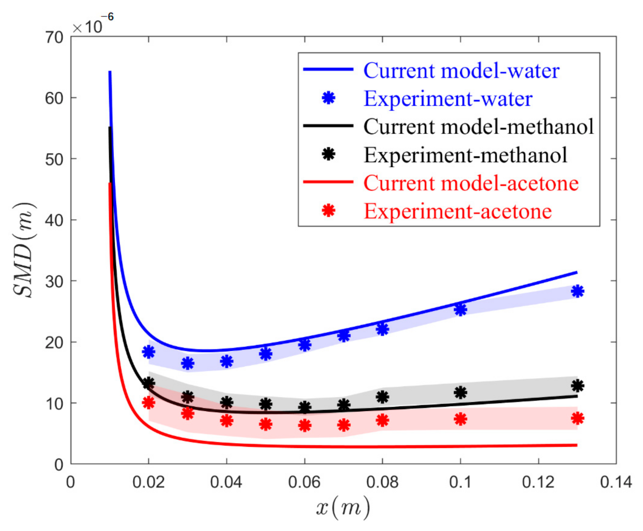
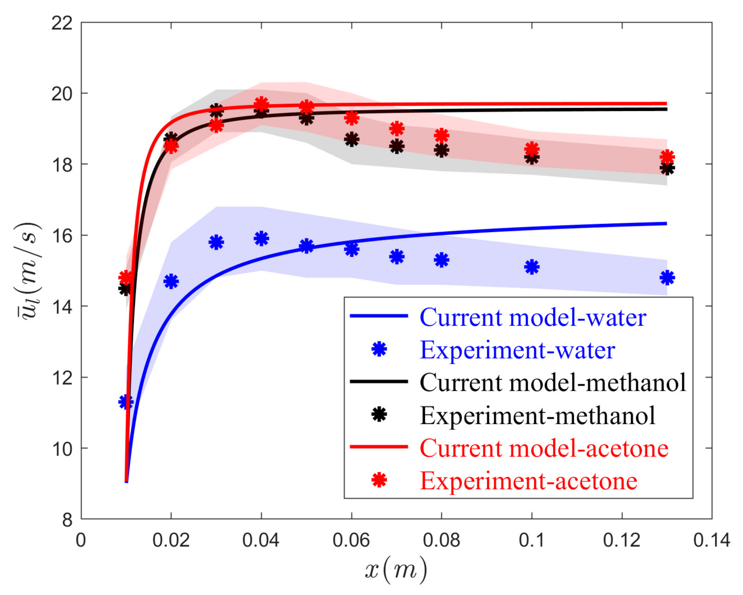
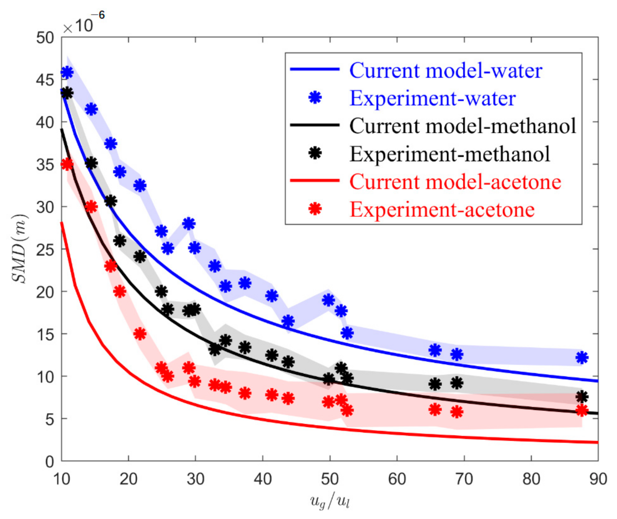
A comparison is made between experimental data and the results from the presented mathematical model in Figure 4, Figure 5 and Figure 6. Overall, good agreement between these two sets of data was obtained. More details on the accuracy of the model were entailed. Due to erratic changes in properties near the nozzle, and risks of non-reproducible data, measurements of droplet size were started around 2 cm downstream of the orifice.
Figure 4 showed the SMD results for ug = 125 m/s (corresponding to the air pressure of 100 kPa) and ul = 2.5 m/s (corresponding to the liquid flow rate of 30 mL/min) for both experimental and modelling data. Shaded areas represented the margin of error (represented by 95% confidence interval calculated based on double replication of the experiments) associated with each measurement. The color of each area was analogous to the associated dataset. A descending and then ascending trend was observed for all the liquid feeds. The common turning point for all is about 5 or 6 cm from the nozzle tip (x/dg~30). Further downstream of the spray cone, the dynamic pressure of the gas can no longer provide sufficient inertial force to overcome the surface tension force. From this location onward, droplets may coalescence and show some increase in the overall measured size. Thus, the extent of coalescence and corresponding slope of ascending line was dependent on surface tension, σ. Based on σ values for these feeds (σwater = 72, σmethanol = 22.7 and σacetone = 25.5 mN/m), water droplets experienced the highest possibility of coalescence, while acetone droplets underwent little to no coalescence. The current model could correctly forecast coalescence and its dependency on σ, as depicted in Figure 4. Nevertheless, the model accuracy was compromised when it came to acetone. Considering almost equal σ for methanol and acetone, and meaningful viscosity difference of these feeds (µmethanol = 0.6 µacetone = 0.32 cp), it appeared that the model overestimated viscosity impacts on SMD. A maximum deviation of 25% between experimental data and the model was observed in this figure. Another point to mention in this figure is the wider shaded area and, therefore, the higher margin of error for acetone feed. This is mostly dictated by the Beam Steering phenomenon due to haziness effects of volatile compounds.
Figure 5 shows the droplet mean velocity in the control volume, ūl, for the three feed liquids at ug = 125 m/s and ul = 2.5 m/s across the jet centerline. The experimental data for all feeds showed an ascending and then descending trend for ūl. Based on these data, droplets for all feeds experienced an initial acceleration followed by a deceleration. The acceleration stage occurs at the immediate vicinity of the nozzle tip due to high relative difference between the liquid and gas flow speeds. After reaching their peak velocity the droplets began to slow and then experienced decreasing speeds. A higher velocity slope was observed for methanol and acetone feeds compared to water during the acceleration period, which means smaller droplets were produced from these feeds (see Figure 4). Our model predicts the trend of experimental data but there are some disagreements in absolute values. Our model successfully simulated the acceleration mode but did not capture the deceleration trend, and the gap between these two sets of data became wider downstream. We thought that incorporating a spatial dependent pressure difference, instead of a constant one which only accounts for pressure loss at the beginning of the injection, would remediate the accuracy of the model. This is because ΔP is following a hyperbolic trend, having its maximum at the gun tip, and dampens along the atomization axis. However, by taking account of a nonlinear ΔP profile, cross-coupling between variables increases and further nonlinearity risks solution convergences.
A pivotal factor in changing droplet size distribution in two-fluid nozzles is gas-to-liquid relative velocity, which is also shown by gas-to-liquid flow rates [32,33]. Experimental and model data on the impacts of gas-to-liquid relative velocities for the three understudied feeds are shown in Figure 6. The accuracy in SMD prediction as a function of relative velocity was reasonably good for water and methanol. Note that the model always underestimated SMD for all the feeds. Although the general hyperbolic trend was still adequately captured by the current model, when it came to acetone, the deviation between the data sets increased. Nevertheless, at higher relative velocities—especially from ug/ul = 25 onward—the accuracy became much better, such that maximum deviation dropped from 50% to almost zero at higher relative velocities. These deviations are most likely due to the overestimating impacts of liquid properties, especially viscosity, on SMD. It has been argued that liquid properties in the two-fluid nozzle are weaker driving forces in determining SMD, compared to process conditions—e.g., relative velocities [28,34,35]. This is especially the case at higher relative velocities where high aerodynamic forces suppress the impacts of fluid properties. Based on Figure 6, SMD could be related to relative velocity through a power law function, S M D = a . ( u g / u l ) b , for which a and b, depending on the feed properties, were in the range of 0.0001–0.0003 and 0.7–0.9, respectively. This is in agreement with the well-known power law dependency of SMD in other experimental works [36,37].
Another apparent observation from Figure 6 was that, at lower ug/ul, by increasing relative velocity, the SMD decreased erratically, while this trend reached a plateau state at higher values of ug/ul. This trend has been explained by the creation of shock cell patterns once air flow is choked at higher Mach numbers [38,39]. These shock waves which were absent at lower relative velocities started forming at higher Mach numbers (0.5) and dampened the rate of SMD decrement.

4.2. Effects of Feed Physiochemical and Relative Velocity

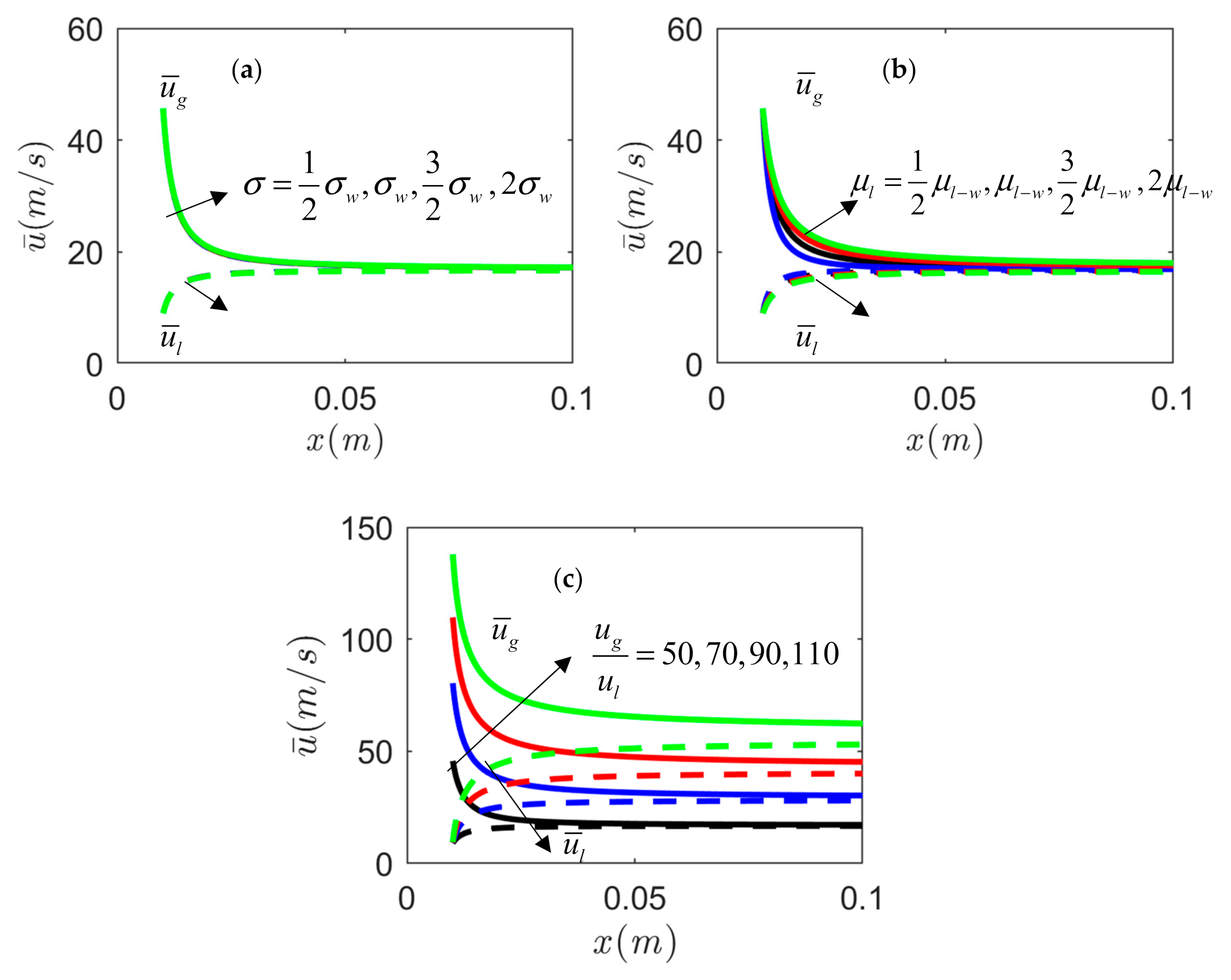
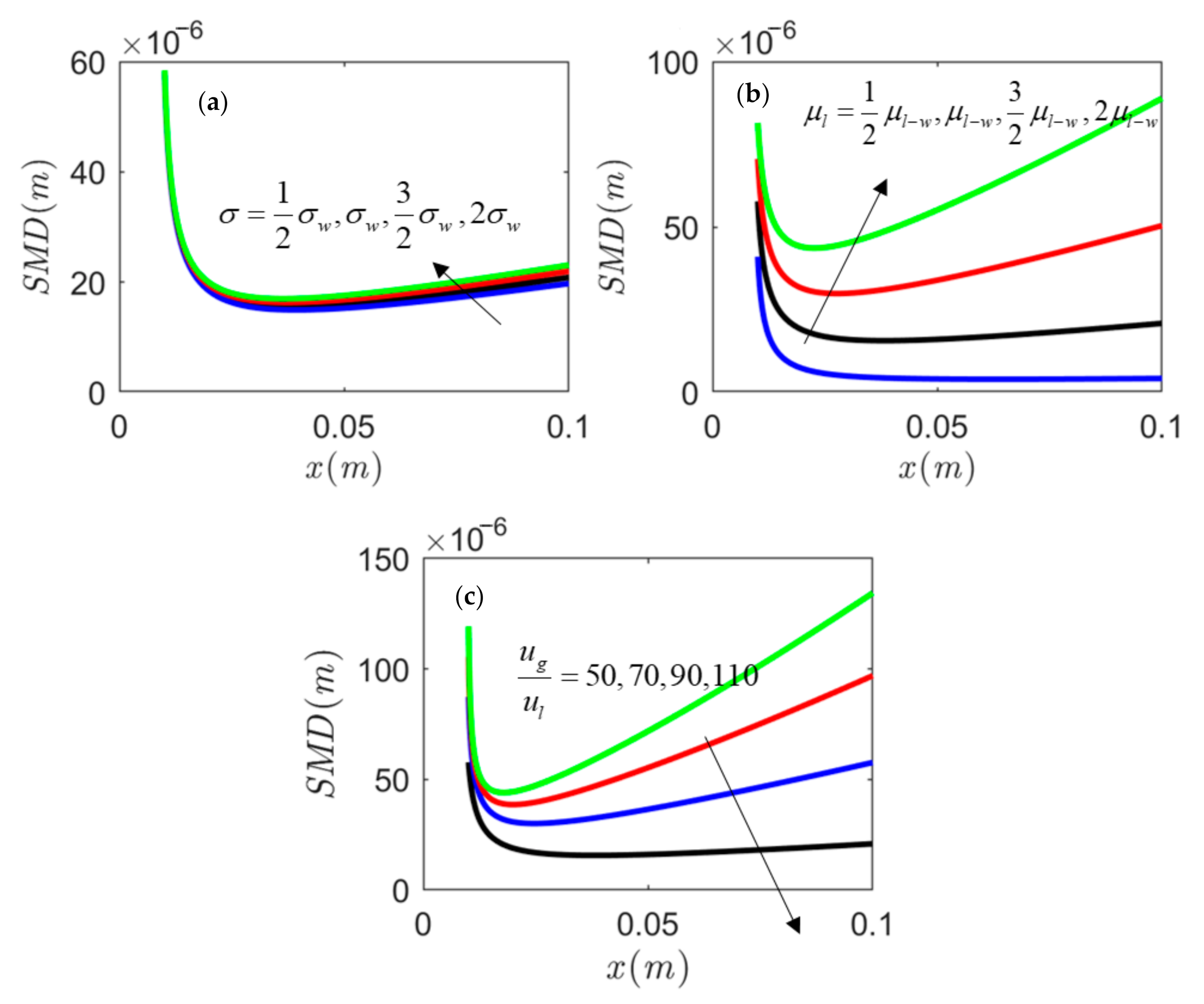
After gauging the impacts of several variables, including feed liquid type and relative velocity on droplet size and velocity of entrained droplets in the downstream control volume, while justifying the current mathematical model, let us turn our attention to the impacts of each individual feed physiochemical property, along with relative velocity impacts on size and velocity distribution across atomization axis. To that end, the data from mathematical model were used. Figure 7 and Figure 8 show the effects of feed viscosity, surface tension and relative velocity in panels (a), (b) and (c), respectively. Based on panel (a) from Figure 7, there is little (if any) influence of σ on gas and liquid velocities in the control volume, ūg and ūl, respectively. The core influence of interfacial surface tension, σ, was reported in the near field of the spray (the first few diameters from the tip), or at low Re g ( = ρ g u g d g / μ g ) , where the impacts of aerodynamic forces are marginal [40]. In our case, where we operate in the far field of the spray and Reg > 5000, σ is not a major player.
On the other hand, in panel (b), the impacts of the feed viscosity are shown to be pronounced at similar operation conditions. Finally, in panel (c) of this figure, the impacts of feed liquid and gas velocities on both ūg and ūl are illustrated. Based on these results, as relative velocity increased, it took longer for the droplets to achieve surrounding gas velocities, which in turn delayed the equilibrium point. At the lowest relative velocity, ug/ul = 50, the equilibrium point occurred at about 2 cm from the nozzle tip. However, this point was shifting to the downstream of the spray plume as relative velocity increased. Given the implicit nature of the presented numerical algorithm and automatic accounting for impacts of SMD on, ūg and ūl, and in turn equilibrium point, we could perceive the influence extent of both ug/ul and SMD on equilibrium location. Knowing that this point (or relaxation length for each droplet), at single droplet scale, is directly related to square of droplet size [41], and the fact that relative velocity and size are adversely correlated, contradicting trends in equilibrium length at two micro and macro scales could be realized. Since the extent of influence of relative velocity was overwhelming compared to droplet size effects, the superimposed impacts on equilibrium point were mainly dictated by this key macroscopic factor.
Spatial changes in SMD as a function of µl, σ and relative velocity are, respectively, depicted in Figure 8a–c. Similar to the observed minor role of σ on gas and droplet velocities in the control volume, effects on SMD were marginal across the jet centerline in this figure. Yet, viscosity was shown to play a significant role, as SMD ramped up by increasing µl. It is noteworthy that, as mentioned before, the current model overestimated the viscosity effects. Thus, a moderating impact of feed viscosity on SMD would be anticipated. Lastly, in (c), interventions of relative velocity were recorded on SMD across the x-axis. The value of the minimum SMD increased with a decrease in relative velocity. After reaching this minimum, SMD followed a nearly linear dependence on the downstream distance with a slope that was dependent on relative velocity. Coalescence phenomena after the turning point (the minimum point) in the breakup process were reversely related to the relative velocity in this sub-figure. A closer look at the driving forces behind coalescence would explain this trend. Velocity fluctuations (due to turbulence) between neighbor droplets result in collision [41]. At higher relative velocities, radial velocity distribution becomes wider, and across the spray radial dimension, droplets possess more uniform velocities [29]. This created a lower probability for collision at higher relative velocities.

4.3. Use of Atomization Scaling Parameters

General trends between operation variables, formulation properties of the feed solution, and the resulting droplet size and velocity for a given nozzle were explored as outlined in the previous subsections. Nonetheless, it would be worthy to adopt quantitative correlations that are deprived of scales and link the droplet size and velocity to physical properties of the feed solution and characteristic properties of the nozzle as a function of processing conditions, across various scales. This may be achieved via describing and capturing the various forces in the atomization process in terms of reduced or dimensionless parameters. This approach is meant to compare the relative magnitude of various forces in terms of fundamental properties. The Weber number (Weg) compares the dynamic gas pressure acting on the liquid sheet to the liquid capillary pressure of the liquid sheet [28], as shown in Equation (8a).
W e g = ρ g d o u g 2 σ ( a ) O h = μ ρ l σ d o ( b )
Here, do is the liquid orifice diameter. ρ is density and subscripts l and g represent liquid and gas, respectively, while other variables were defined previously. When Weg rises, the atomization mechanism appears to be more intense, and the ensued droplets are smaller [42]. When a gas stream is directed onto a liquid surface, oscillations and waves on the surface of the liquid are produced and these promote the fragmentation process of bulk liquid. This phenomenon is captured in the numerator of Equation (8a). The resisting force to these oscillations is liquid viscous force—captured in the denominator of Equation (8a). Another dimensionless number that relates gas inertia to the liquid viscous force is the Reynold’s number (Re) [43,44]. However, while working with both We and Re numbers, to exclude inertia effects, another pi-number, the Ohnesorge number (Oh), can be extracted via combination of We and Re, Oh = We0.5/Re. This dimensionless number is entirely dependent on feed properties and geometry of liquid orifice. The Oh number is defined as shown in Equation (8b).
The ratio of the magnitude of the involved forces associated with the atomization process may be realized with consideration of both the Weg and Oh numbers. In addition to the engaged forces, the information on phases mass flow rates are vital to analyze the dynamics of the atomization system. The gas-to-liquid ratio, G L R = m ˙ g / m ˙ l , is defined as the ratio between air and liquid mass flow rates and has frequently been cited as a dimensionless quantity which represents the atomization operating conditions [45].
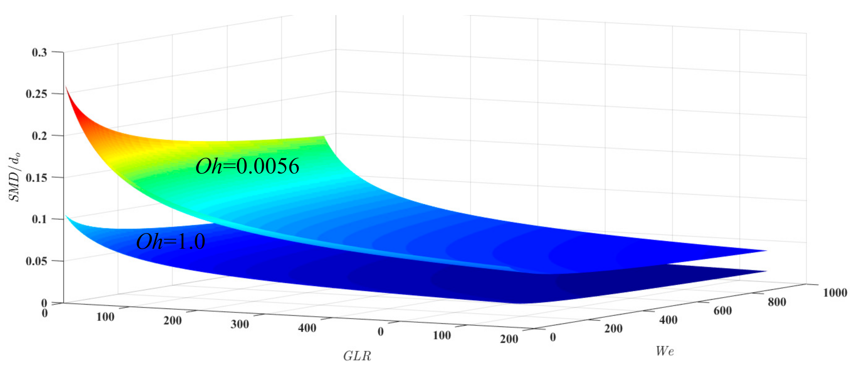
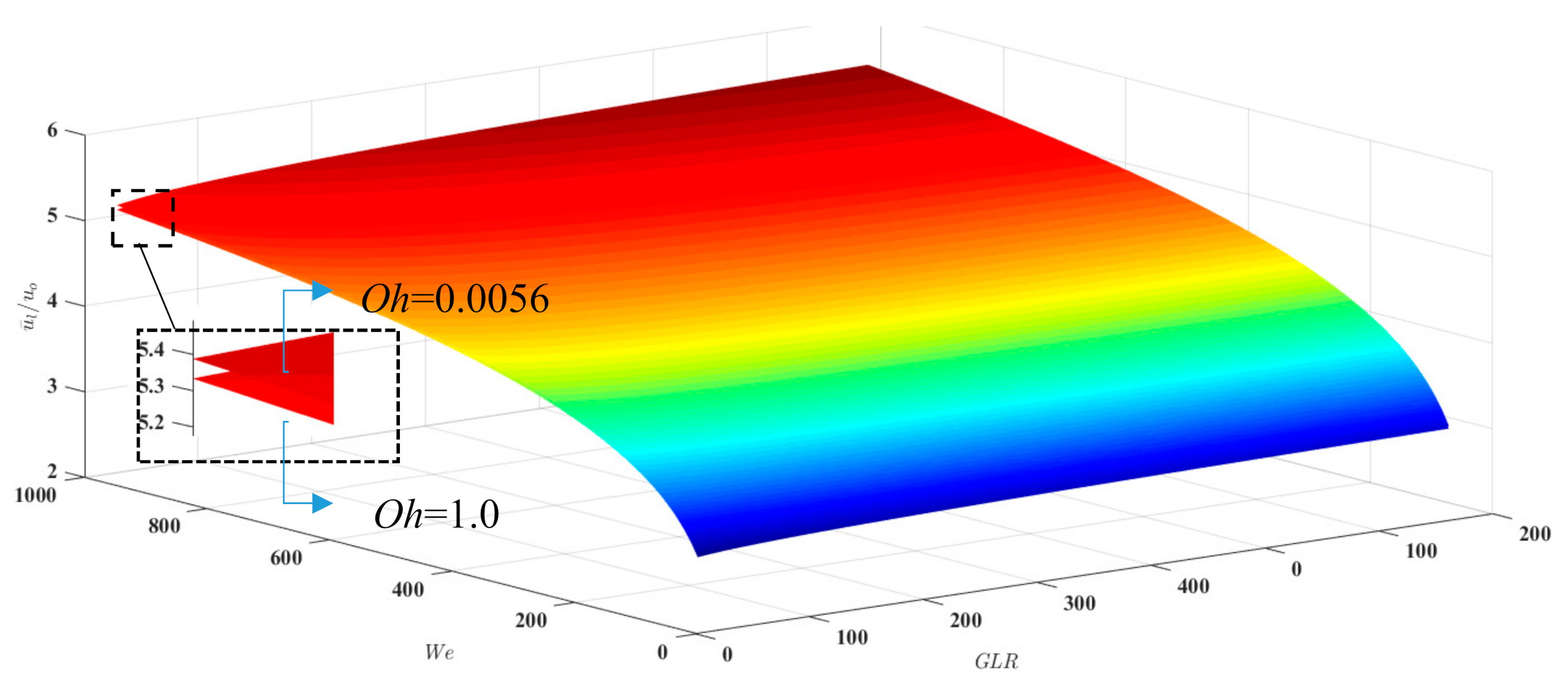
Using the current mathematical model, a dataset was established and then converted to the presented dimensionless parameters to describe normalized parameters based on the ratioing of, droplet size and liquid orifice dimeter (SMD/do), and droplet velocity and liquid velocity at the orifice (ūl/uo). The 3D response plots shown in Figure 9 and Figure 10 provide a visual representation of the changes in normalized droplet size and velocity across the operational/simulation ranges studied here. Plots were given at two Ohs, one for water (Oh = 0.0056) and one for a typical honey at elevated temperature (Oh = 1.0) [46]. These representations of the data allow for optimization of the process conditions. For instance, the plots indicate that, for very fine droplet formation, the major critical factors are GLR and Weg (i.e., noticeable change in droplet size are shown as a function of these dimensionless numbers). These plots reiterated our earlier observations with respect to feed attributes’ role in atomization. According to these figures, Oh, which is merely dependent on feed attributes, plays a very minor role in normalized velocity, yet its effects are still noticeable on a normalized drop size.
Please note that, even though Figure 9 and Figure 10 are shown for a single point along the atomization longitudinal axis (x/dg~30), one can reproduce similar predictions, based on paramount non-dimensional parameters, for other points along this axis, wherein breakup is finished.
Presenting a conservation-based model to predict major quality measures of two-fluid nozzles can help improve performance of equipment and scale-up, and complement CFD of sprays. During scale-up process, a rough estimation of droplet size and velocity distribution would bring in substantive information on determining design specifications to reach similar product quality across different scales. The bottleneck in this area is to tailor sprays to have analogous droplet size and proportional velocity so that droplets across various scales experience similar evaporation rates, and therefore no loss in powder quality [1,4].
Furthermore, during CFD analysis of sprays, setting the initial conditions for the drop size and velocity has been the major obstacle in accurate simulations. Once the initial drop size and velocity are properly set, then there are several reliable methods available for subsequent tracking of both the gas and liquid/solid phases, Eulerian–Lagrangian calculations of particulate systems [47,48]. Phase change and transfer of mass and energy can also be effectively treated using thermodynamic modules. Thus, a capability to specify the droplet initial conditions, based on the first principles, is vital to serve as a surrogate for ad hoc models presently used in many commercially available software packages.

5. Conclusions

This study investigated the characterization of spray issuing from a two-fluid nozzle adopted in a laboratory-scale spray dryer. With a simplified method based on conservation equations, the sensitivity of SMD and velocity distribution of both phases are examined in light of feed properties and process conditions. Additionally, experimental study was conducted at ambient conditions using water, methanol and acetone as model fluids to provide needed contrast in physiochemical properties, such as surface tension, density and viscosity. Spray quality—i.e., drop size distribution—and velocity were detected by a laser diffraction and high-speed camera, respectively, for qualitative investigation of primary atomization and calibration of our model. High fidelity of the employed model was confirmed by the agreement of the two experimental and model results. Lastly, an attempt was done to utilize non-scaled parameters to characterize the atomization process. Non-dimensional parameters driving underlying atomization were used to describe normalized droplet size and drop velocity. Although our analysis retained the essential transport mechanisms and could predict droplet size, velocity and equilibrium point (i.e., the point where droplet and gas velocities equilibrate), there are various effects that should be incorporated in future extensions of the model. For example, the impacts of viscosity were overestimated by the model. Moreover, descending droplet velocity after the turning point was not captured by the model. Future study will elaborate on these two challenges and offer remediate to further narrow the gap. The authors hope this simplified modelling tool provides rigorous estimation on pivotal spray characteristics needed for sensitivity analysis and scale-up processes.

Author Contributions

Conceptualization, S.P. and H.R.C.; methodology, S.P.; software, S.P. and F.B.; validation, S.P. and F.B.; formal analysis, N.K.A. and K.S.; investigation, S.P.; resources, S.P.; data curation, S.P.; writing—original draft preparation, S.P., N.K.A. and K.S.; writing—review and editing, N.K.A. and K.S.; visualization, S.P. and H.R.C.; supervision, N.K.A.; project administration, S.P.; funding acquisition, N.K.A. All authors have read and agreed to the published version of the manuscript.

Funding

Funding from IR4TD at University of Kentucky.

Conflicts of Interest

The authors declare no conflict of interest.

Nomenclatures

Normal
ASurface area (m2)
CDDrag coefficient
DDroplet diameter (m)
dDifferential
dgGas orifice diameter (m)
doLiquid orifice diameter (m)
GLRRatio of Gas to liquid mass flow rates
Kproportionality constant for the viscous dissipation term
Mass flow rate (kg/s)
nDrop number density
OhOhnesorge number
PPressure
p(D)Normalized drop size distribution function
ReReynolds number
SMDSauter mean diameter (m)
uVelocity (m/s)
ūMean velocity in control volume (m/s)
WeWeber number
XAxial coordination (m)
Vvolume of the spray bounded by A and spray length (m3)
Greek Symbols
ρDensity (kg/m3)
μLatent heat of vaporization (J/kg)
Δ Difference in states
σSurface tension (N/m)
Subscripts
gGas phase
iIndex for droplet size bins
lLiquid phase
oOrifice
wwater
xAtomization axis

References

  1. Shrigondekar, H.; Chowdhury, A.; Prabhu, S. Characterization of solid-cone simplex mist nozzles. Fire Saf. J. 2020, 111, 102936. [Google Scholar] [CrossRef]
  2. Tang, M.; Chen, S.-C.; Pui, D.Y. An improved atomizer with high output of nanoparticles. J. Aerosol Sci. 2018, 124, 10–16. [Google Scholar] [CrossRef]
  3. Sapra, M.; Mayya, Y.; Venkataraman, C. Air-jet atomization for preparation of lipid nanoparticles: Dependence of size on solute concentration. J. Aerosol Sci. 2016, 100, 1–13. [Google Scholar] [CrossRef]
  4. Poozesh, S.; Bilgili, E. Scale-up of pharmaceutical spray drying using scale-up rules: A review. Int. J. Pharm. 2019, 562, 271–292. [Google Scholar] [CrossRef] [PubMed]
  5. Sander, A.; Penović, T. Droplet Size Distribution Obtained by Atomization with Two-Fluid Nozzles in a Spray Dryer. Chem. Eng. Technol. 2014, 37, 2073–2084. [Google Scholar] [CrossRef]
  6. Andrade, R.D.; Skurtys, O.; Osorio, F.A. Atomizing spray systems for application of edible coatings. Compr. Rev. Food Sci. Food Saf. 2012, 11, 323–337. [Google Scholar] [CrossRef]
  7. Poozesh, S.; Setiawan, N.; Arce, F.; Sundararajan, P.; Della Rocca, J.; Rumondor, A.; Wei, D.; Wenslow, R.; Xi, H.; Zhang, S. Understanding the process-product-performance interplay of spray dried drug-polymer systems through complete structural and chemical characterization of single spray dried particles. Powder Technol. 2017, 320, 685–695. [Google Scholar] [CrossRef]
  8. Oh, Y.S.; Choi, D.Y.; Son, J.Y.; Kim, B.Y.; Kang, H.W.; Chang, C.B.; Moon, J.-T.; Sung, H.J. Breakup behavior of a molten metal jet. Int. J. Heat Fluid Flow 2014, 50, 27–37. [Google Scholar] [CrossRef]
  9. Babinsky, E.; Sojka, P. Modeling drop size distributions. Prog. Energy Combust. Sci. 2002, 28, 303–329. [Google Scholar] [CrossRef]
  10. Beaucage, G.; Kammler, H.K.; Pratsinis, S.E. Particle size distributions from small-angle scattering using global scattering functions. J. Appl. Crystallogr. 2004, 37, 523–535. [Google Scholar] [CrossRef]
  11. Yan, K.; Ning, Z.; Lü, M.; Sun, C. Study on droplet size and velocity distributions of a pressure swirl atomizer based on the Maximum Entropy Formalism. Entropy 2015, 17, 580–593. [Google Scholar] [CrossRef] [Green Version]
  12. Dasgupta, D.; Nath, S.; Bhanja, D. Dual-mode nonlinear instability analysis of a confined planar liquid sheet sandwiched between two gas streams of unequal velocities and prediction of droplet size and velocity distribution using maximum entropy formulation. Phys. Fluids 2018, 30, 044104. [Google Scholar] [CrossRef]
  13. Kolodnytska, R.; Skurativskyi, S.; Moskvin, P. Maximum entropy method for biodiesel spray droplet distribution. In Proceedings of the ILASS Europe. 28th European Conference on Liquid Atomization and Spray Systems, Valencia, Spain, 6–8 September 2017; pp. 464–471. [Google Scholar]
  14. Pei, Y.; Hawkes, E.R.; Kook, S.; Goldin, G.M.; Lu, T. Modelling n-dodecane spray and combustion with the transported probability density function method. Combust. Flame 2015, 162, 2006–2019. [Google Scholar] [CrossRef] [Green Version]
  15. Hu, Y.; Gutheil, E. Numerical simulations of turbulent poly-disperse acetone spray flows using a transported joint probability density function method. At. Sprays 2016, 26, 275–299. [Google Scholar] [CrossRef]
  16. González-Tello, P.; Camacho, F.; Vicaria, J.; González, P. A modified Nukiyama–Tanasawa distribution function and a Rosin–Rammler model for the particle-size-distribution analysis. Powder Technol. 2008, 186, 278–281. [Google Scholar] [CrossRef]
  17. Nukiyama, S.; Tanazawa, Y. An experiment on the atomization of liquid by means of an air stream. Trans. JSME 1942, 4, 8. [Google Scholar]
  18. Pacheco, C.; Pina, J.; Saleh, K. Atomization of molten materials for particle coating: Prediction of mean droplet size for two-fluid nozzles. At. Sprays 2016, 26, 1031–1050. [Google Scholar] [CrossRef]
  19. Castel, V.; Rubiolo, A.C.; Carrara, C.R. Droplet size distribution, rheological behavior and stability of corn oil emulsions stabilized by a novel hydrocolloid (Brea gum) compared with gum arabic. Food Hydrocoll. 2017, 63, 170–177. [Google Scholar] [CrossRef]
  20. Tomar, G.; Fuster, D.; Zaleski, S.; Popinet, S. Multiscale simulations of primary atomization. Comput. Fluids 2010, 39, 1864–1874. [Google Scholar] [CrossRef] [Green Version]
  21. Tryggvason, G.; Scardovelli, R.; Zaleski, S. Direct Numerical Simulations of Gas—Liquid Multiphase Flows; Cambridge University Press: Cambridge, UK, 2011. [Google Scholar]
  22. Vincent, S.; Osmar, L.; Estivalezes, J.-L.; Zaleski, S.; Auguste, F.; Aniszewski, W.; Ling, Y.; Menard, T.; Pedrono, A.; Magnaudet, J. A phase inversion benchmark for multiscale multiphase flows. arXiv 2019, arXiv:1906.02655. [Google Scholar]
  23. Ling, Y.; Fuster, D.; Tryggvason, G.; Zaleski, S. A two-phase mixing layer between parallel gas and liquid streams: Multiphase turbulence statistics and influence of interfacial instability. J. Fluid Mech. 2019, 859, 268–307. [Google Scholar] [CrossRef] [Green Version]
  24. Jain, S.S.; Tyagi, N.; Prakash, R.S.; Ravikrishna, R.; Tomar, G. Secondary breakup of drops at moderate Weber numbers: Effect of Density ratio and Reynolds number. Int. J. Multiph. Flow 2019, 117, 25–41. [Google Scholar] [CrossRef] [Green Version]
  25. Lee, T.-W.; An, K. Quadratic formula for determining the drop size in pressure-atomized sprays with and without swirl. Phys. Fluids 2016, 28, 063302. [Google Scholar] [CrossRef]
  26. Lee, T.-W.; Park, J. Determination of the Drop Size During Air-Blast Atomization. J. Fluids Eng. 2019, 141, 121301. [Google Scholar] [CrossRef]
  27. Lee, T.-W.; Ryu, J.-H. Analyses of spray break-up mechanisms using the integral form of the conservation equations. Combust. Theory Model. 2014, 18, 89–100. [Google Scholar] [CrossRef]
  28. Hede, P.D.; Bach, P.; Jensen, A.D. Two-fluid spray atomisation and pneumatic nozzles for fluid bed coating/agglomeration purposes: A review. Chem. Eng. Sci. 2008, 63, 3821–3842. [Google Scholar] [CrossRef]
  29. Poozesh, S.; Grib, S.W.; Renfro, M.W.; Marsac, P.J. Near-field dynamics of high-speed spray dryer coannular two fluid nozzle: Effects of operational conditions and formulations. Powder Technol. 2018, 333, 439–448. [Google Scholar] [CrossRef]
  30. Sänger, A.; Jakobs, T.; Djordjevic, N.; Kolb, T. Effect of primary instability of a high viscous liquid jet on the spray quality generated by a twin-fluid atomizer. In Proceedings of the European Conference for Liquid Atomization and Spray System (ILASS), Bremen, Germany, 8–10 September 2014; pp. 8–10. [Google Scholar]
  31. Pougatch, K.; Salcudean, M.; Chan, E.; Knapper, B. A two-fluid model of gas-assisted atomization including flow through the nozzle, phase inversion, and spray dispersion. Int. J. Multiph. Flow 2009, 35, 661–675. [Google Scholar] [CrossRef]
  32. Leroux, B.; Delabroy, O.; Lacas, F. Experimental study of coaxial atomizers scaling. Part I: Dense core zone. At. Sprays 2007, 17, 381–407. [Google Scholar] [CrossRef]
  33. Aliseda, A.; Hopfinger, E.J.; Lasheras, J.C.; Kremer, D.; Berchielli, A.; Connolly, E. Atomization of viscous and non-Newtonian liquids by a coaxial, high-speed gas jet. Experiments and droplet size modeling. Int. J. Multiph. Flow 2008, 34, 161–175. [Google Scholar] [CrossRef] [Green Version]
  34. Poozesh, S.; Setiawan, N.; Akafuah, N.K.; Saito, K.; Marsac, P.J. Assessment of predictive models for characterizing the atomization process in a spray dryer’s bi-fluid nozzle. Chem. Eng. Sci. 2018, 180, 42–51. [Google Scholar] [CrossRef]
  35. Dennison, T.J.; Smith, J.; Hofmann, M.P.; Bland, C.E.; Badhan, R.K.; Al-Khattawi, A.; Mohammed, A.R. Design of experiments to study the impact of process parameters on droplet size and development of non-invasive imaging techniques in tablet coating. PLoS ONE 2016, 11, e0157267. [Google Scholar] [CrossRef] [PubMed]
  36. Xiao, F.; Dianat, M.; McGuirk, J.J. LES of turbulent liquid jet primary breakup in turbulent coaxial air flow. Int. J. Multiph. Flow 2014, 60, 103–118. [Google Scholar] [CrossRef] [Green Version]
  37. Charalampous, G.; Hardalupas, Y.; Taylor, A. Structure of the continuous liquid jet core during coaxial air-blast atomisation. Int. J. Spray Combust. Dyn. 2009, 1, 389–415. [Google Scholar] [CrossRef]
  38. Kaiser, R.; Li, C.; Yang, S.; Lee, D. A numerical simulation study of the path-resolved breakup behaviors of molten metal in high-pressure gas atomization: With emphasis on the role of shock waves in the gas/molten metal interaction. Adv. Powder Technol. 2018, 29, 623–630. [Google Scholar] [CrossRef]
  39. Kihm, K.D.; Chigier, N. Effect of shock waves on liquid atomization of a two-dimensional airblast atomizer. At. Sprays 1991, 1, 113–136. [Google Scholar] [CrossRef]
  40. Urbán, A.; Zaremba, M.; Malý, M.; Józsa, V.; Jedelský, J. Droplet dynamics and size characterization of high-velocity airblast atomization. Int. J. Multiph. Flow 2017, 95, 1–11. [Google Scholar] [CrossRef] [Green Version]
  41. Lasheras, J.; Villermaux, E.; Hopfinger, E. Break-up and atomization of a round water jet by a high-speed annular air jet. J. Fluid Mech. 1998, 357, 351–379. [Google Scholar] [CrossRef] [Green Version]
  42. Chigier, N.; Farago, Z. Morphological classification of disintegration of round liquid jets in a coaxial air stream. At. Sprays 1992, 2, 137–153. [Google Scholar] [CrossRef]
  43. Poozesh, S.; Akafuah, N.; Saito, K. New criteria for filament breakup in droplet-on-demand inkjet printing using volume of fluid (VOF) method. Korean J. Chem. Eng. 2016, 33, 775–781. [Google Scholar] [CrossRef]
  44. Saito, K.; Williams, F. Scale Modeling in the Age of High-Speed Computation. In Progress in Scale Modeling, Volume II; Springer: Berlin/Heidelberg, Germany, 2015; pp. 1–18. [Google Scholar]
  45. Lefebvre, A.H. Airblast atomization. Prog. Energy Combust. Sci. 1980, 6, 233–261. [Google Scholar] [CrossRef]
  46. Oroian, M. Measurement, prediction and correlation of density, viscosity, surface tension and ultrasonic velocity of different honey types at different temperatures. J. Food Eng. 2013, 119, 167–172. [Google Scholar] [CrossRef]
  47. Kolaitis, D.; Founti, M. A comparative study of numerical models for Eulerian–Lagrangian simulations of turbulent evaporating sprays. Int. J. Heat Fluid Flow 2006, 27, 424–435. [Google Scholar] [CrossRef]
  48. Poozesh, S.; Lu, K.; Marsac, P.J. On the particle formation in spray drying process for bio-pharmaceutical applications: Interrogating a new model via computational fluid dynamics. Int. J. Heat Mass Transf. 2018, 122, 863–876. [Google Scholar] [CrossRef]
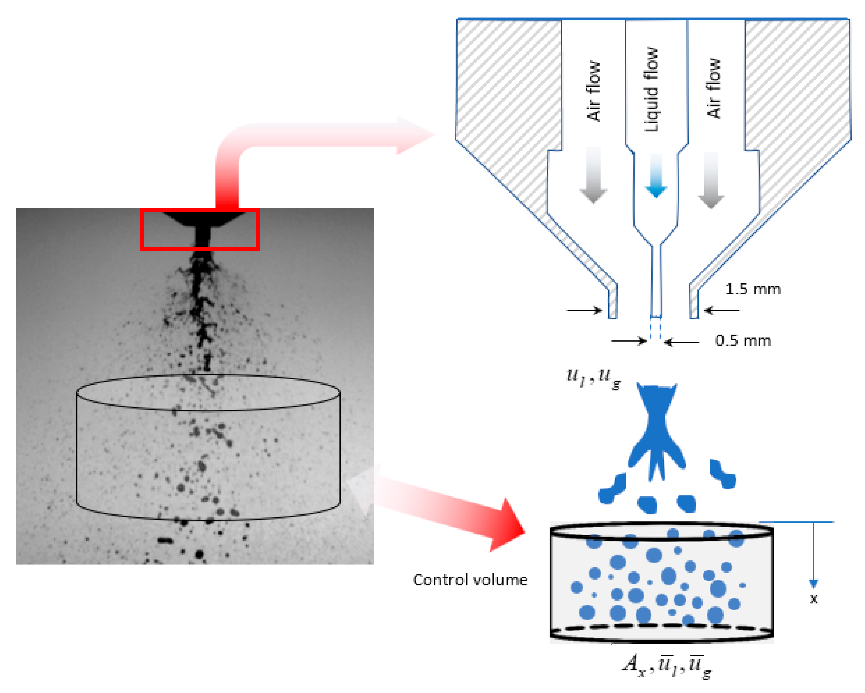
Figure 1. Left: near-field breakup process for two-fluid nozzle captured by high-speed imaging at a frame rate of 49 kHz [29]; right: spray configuration, and understudied control volume.
Fluids 05 00231 g001
Figure 2. Experimental rig for droplet size measurements.
Fluids 05 00231 g002
Figure 3. The employed algorithm to numerically obtain ūl, ūg and SMD across the jet centerline.
Fluids 05 00231 g003
Figure 4. Experimental data (via laser diffraction by Spraytec) and current model results on SMD along the atomization axis for the three liquid feeds of water, methanol and acetone at ug = 125 m/s and ul = 2.5 m/s. Shaded areas show the error associated with each measurement.
Fluids 05 00231 g004
Figure 5. Experimental data (via high-speed flow visualizations) and current model results on ūl along the atomization axis for the three liquid feeds of water, methanol and acetone at ug = 125 m/s and ul = 2.5 m/s.
Fluids 05 00231 g005
Figure 6. Experimental data and current model results on SMD as a function of gas-to-liquid relative velocity at 5 cm from the nozzle tip along x for the three liquid feeds of water, methanol and acetone.
Fluids 05 00231 g006
Figure 7. Impacts of formulation properties, σ and µl, and injection gas and liquid velocity ratios, ug/ul, on ūg and ūl (shown in (ac), respectively) solid lines are representing ūg, while dash lines are showing ūl. In the top panels, ug = 125 and ul = 2.5 m/s. Arrow directions show the incremental values.
Fluids 05 00231 g007
Figure 8. Impacts of formulation properties, σ and µl, and injection point gas and liquid velocity ratios, ug/ul, on SMD (shown in (ac), respectively). In the top panels, ug = 125 and ul = 2.5 m/s. Arrow directions show the incremental values.
Fluids 05 00231 g008
Figure 9. Three-dimensional response plot of SMD/do as a function of We and GLR for Oh = 0.0056 and Oh = 1 at x/dg~30.
Fluids 05 00231 g009
Figure 10. Three-dimensional response plot of ūl/uo as a function of We and GLR for Oh = 0.0056 and Oh = 1 at x/dg~30. A zoom in box is provided to observe the difference in responses.
Fluids 05 00231 g010
Publisher’s Note: MDPI stays neutral with regard to jurisdictional claims in published maps and institutional affiliations.