Article

Mean Drift Forces on Vertical Cylindrical Bodies Placed in Front of a Breakwater

by
Dimitrios Konispoliatis
* and
Spyridon Mavrakos
School of Naval Architecture and Marine Engineering, National Technical University of Athens, 9 Heroön Polytechniou Ave., Zografos Campus, 15773 Athens, Greece
*
Author to whom correspondence should be addressed.
Fluids 2020, 5(3), 148; https://doi.org/10.3390/fluids5030148
Submission received: 27 July 2020 / Revised: 26 August 2020 / Accepted: 29 August 2020 / Published: 31 August 2020
(This article belongs to the Special Issue Wind and Wave Renewable Energy Systems)

Abstract

:
This paper presents a numerical and experimental investigation of the second-order steady horizontal and vertical drift forces acting on cylindrical bodies in regular waves. The examined bodies are either kept restrained in front of a vertical breakwater or are considered free- floating when alone in the wave field. Two principally different approaches for mean drift forces determination are described: the momentum conservation principle and the direct integration of all pressure contributions upon the instantaneous wetted surface of the bodies, whereas, for the solution of the associated diffraction and motion radiation problems, analytical and panel methodologies are applied. The hydrodynamic interaction phenomenon between the bodies and the adjacent breakwater are taken into account by using the method of images. Theoretical and numerical results, concerning the horizontal and the vertical drift forces, are presented and compared with each other. Furthermore, additional comparisons are made with experimental data obtained during an experimental campaign at French research institute for exploitation of the sea (IFREMER), in France.

1. Introduction

The numerical and theoretical prediction of drift forces upon floating bodies in regular and random waves is not a recent concept. Several efforts related its importance and the determination methods have been presented in the literature since the first theoretical approach was presented in Reference [1], where the steady drift force acting on a fixed vertical circular cylinder in waves was calculated. Drift forces are second-order forces, time-independent if the motion of the body is harmonic or slowly varying if the body is subjected to the action of random waves. They are generally small in magnitude, as compared to their first-order oscillatory counterparts, which, as a result, do not influence the body’s oscillatory motions. Nevertheless, in situations where there is a lack or very small restoring forces, originating either from the mooring system or with a hydrodynamic nature, the drift forces may cause large mean and slowly-varying excursions of the body from its mean position if they act over sufficiently long periods of time. Representative examples of this phenomenon are the drifting motion of a floating body in the horizontal plane, resulting in its large horizontal motions in regular waves [2,3], and its slow-drift pitch and roll motions which may affect the body’s stability in irregular waves [4,5]. Furthermore, since the drift forces are closely dependent on water depth, i.e., they increase in magnitude in shallow waters, their accurate prediction in shallow water is important. In Reference [6], comprehensive test results concerning the drift forces and their effect on different arrangements of an Liquefied Natural Gas (LNG) carrier and floating production barge in multi-directional waves were presented.
The previous examples demonstrate that the mean and slowly-varying second-order wave excitations may induce significant dynamic responses on floating structures, and therefore, it is important to understand them and to develop and validate numerical and theoretical prediction methods for their accurate prediction. In this respect, the reader is reminded that the accurate evaluation of the quadratic transfer functions matrix (QTF’s) of the slowly-varying second order wave excitations (i.e., second-order difference-frequency excitations) requires a solution of the time-consuming second order difference–frequency ( ω i   ω j ) body–wave interaction problem in bi-chromatic waves for all off-diagonal terms of the QTF’s matrix. The main diagonal terms of the QTF’s, i.e., for zero difference frequency ( ω i =   ω j ), correspond to the second order mean drift forces in monochromatic waves and their evaluation only depends on first-order quantities. In order to avoid the time consuming calculation of the second-order velocity potential, a usual procedure for calculating the second-order difference-frequency excitations, introduced in Reference [7], is to simplify the QTF by representing the difference–frequency terms by means of the zero difference results, i.e., by the mean drift forces, provided that the natural frequency associated with slow-drift motions is sufficiently small. In this way, the second-order problem is simplified, along with minimizing the computational effort. It is therefore evident that the development and validation of accurate numerical and theoretical prediction methods of the drift forces is important, since they can form a basis for evaluating, in many cases, the low-frequency dynamic responses of floating bodies.

1.1. Numerical/Theoretical Calculation Methods

Two principally different approaches have been presented in the literature for the calculation of the mean drift wave loads, namely the momentum conservation principle and the direct integration method. The momentum conservation principle, i.e., the far field solution, relates the forces on the examined body to the forces on the exterior fixed or moving control surfaces and the rate of change of the fluid momentum between the control surfaces and the body. The direct integration method, i.e., the near-field solution, relies on the fluid pressure direct integration over the instantaneous wetted surface of the examined body. Nevertheless, both methods require a solution to the linearized body-wave and breakwater (if applicable) interaction problem, taking into account the diffraction and radiation phenomena.
The first method, i.e., the far field solution, was introduced in Reference [8] for the calculation of the mean horizontal forces on bodies in infinite water depth, whereas, in Reference [9], the method was extended, including calculations of the yaw drift moments. In Reference [10], the momentum method was combined with a sink-source technique to obtain the first order potential, deriving equally valid expressions for infinite and finite water depths. In these studies, the control surface has been considered as infinite and use is made of the far-field asymptotic behavior of the velocity potential to express the second-order mean loads in terms of Kochin functions. However, the application of the far-field method for the heave drift forces and the roll and pitch drift moments leads to expressions of infinite integrals on the free surface, supplemented by corresponding integrals on the sea bottom. Thus, in order to circumvent this issue for a submerged body, the infinite free-surface integrals were expressed in terms of Kochin functions on the body’s wetted surface in Reference [11]. Furthermore, this method was extended in Reference [12] for surface piercing bodies, whereas, in Reference [13], the mean wetted surface boundary of the body was introduced as a control surface. In References [14,15], the infinite free-surface and sea-bottom integrals of free surface piercing vertical bodies of arbitrary shape were transformed in closed form, applying analytical representation of the velocity potential around each examined body. Further, in References [16,17], the second order steady forces and yaw moment at the forward speed was calculated by utilizing the Fourier transform theory.
The near-field method, introduced in Reference [18], provides expressions for all the components of the second-order steady forces and moments. This method was extended by References [13,19,20] to account for some additional quadratic terms of hydrostatic origin. The fluid pressure over the instantaneous body surface is expressed in terms of its values on the mean body’s position through the Taylor expansions. The method requires the evaluation of both the velocity potential and its derivatives on the body’s wetted surface. Thus, it is very sensitive to the panel discretization of the body’s surface, particularly near the free surface and close to sharp corners [21]. Therefore, in Reference [22], a stabilized higher-order boundary element method has been applied to solve the wave-drift forces with the presence of steady or slowing, varying velocities, producing accurate results on bottom-mounted and truncated vertical circular cylinders.
Recently, the so-called middle field formulation was proposed to overcome the convergence problems of the near field method [23,24]. In this case, the control surface was located at a finite distance from the examined body. Additionally, indicative reviews on drift forces on several examined floating bodies or structures, using the aforementioned calculation methods, were shown in References [25,26,27].

1.2. Experimental Validation Tests

Despite the increased interest in mean drift forces, only a few studies scaled down the experimental tests that are available in the literature. In Reference [28], the horizontal mean drift force on a tension leg platform in regular and irregular waves was investigated by model tests in both frequency and time domains. In Reference [29], the second order wave drift forces on two floating bodies, situated side by side, were calculated and compared with experimental results. Moreover, numerical and experimental results concerning the mean drift forces exerted on an array of free-floating Oscillating Water Column devices (OWCs) were presented in Reference [30]. Theoretical results were obtained using both far and near-field methods and were compared with the experimental ones. Furthermore, in Reference [31], the slowly varying wave drift forces were investigated experimentally on a very large floating structure, whereas, in Reference [32], the slow drift wave responses of the floating bodies were experimentally and numerically studied for several bathymetries.

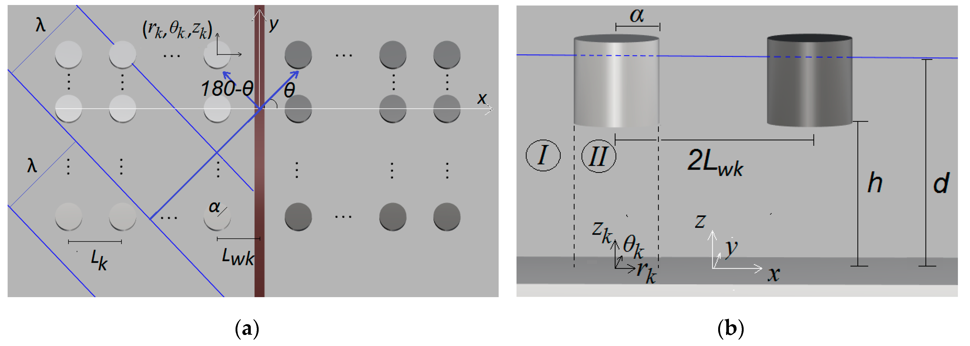
1.3. Body-Breakwater Simulation Methods

The hydrodynamic performance of cylinders in multi-body arrays is greatly influenced by the continuous interactions of the propagating waves with the waves diffracted by the bodies. In particular, when the bodies are placed in front of a vertical breakwater, these interactions are amplified due to the presence of the vertical wall, causing increased hydrodynamic loadings and free surface elevations. Despite the effect of wave reflections, they can be beneficial for wave energy converters, by increasing their motions, and as a result, their power absorption, which may result in stability and structural issues in the floating structures that are placed nearshore. Indicative theoretical and experimental studies concerning the effect of a vertical wall on the hydrodynamic characteristics of an array of five floating cylindrical bodies are studied in References [33,34], whereas, in Reference [35], the resonances of a freely floating half immersed cylinder in front of a vertical rigid breakwater have been investigated. Additionally, in References [36,37,38,39,40,41], the corresponding wave diffraction problem, as well as the motion- and pressure- radiation problems of a single truncated cylinder and of an oscillating water column wave energy converter (WEC), placed in front of a vertical wall, was examined.
In these works, a fully reflecting, bottom-mounted, vertical wall of infinite length is assumed and the method of images method is used to describe the fluid around the examined bodies in front of a breakwater. According to this method, the system of the breakwater and the N number of bodies is equivalent to an array of 2N number of bodies consisting of the initial ones and their image of virtual solids with respect to the vertical wall, without, however, the presence of the breakwater, which are exposed to the action of surface incident waves.
Furthermore, the effect of a finite length breakwater on the hydrodynamics of an array of oblate spheroidal WECs has been studied in Reference [42]. Nevertheless, the breakwater is being considered as an elliptical cylinder with zero semi-minor axes.

1.4. Interaction Phenomena Calculation Methods

The main difference between an isolated body and an array of bodies placed in front of a breakwater is the hydrodynamic interaction phenomena. Each body of the array and the vertical wall scatters waves towards the others, which in turn scatter waves, contributing to the excitation of the initial body and so on. These wave interaction phenomena are determined by applying two different methods: a) the physical idea of multiple scattering and b) the direct matrix inversion method. The multiple scattering approach was first suggested in Reference [43] for acoustic radiation by an array of parallel cylinders, whereas, in Reference [44,45], the method was applied to the free-surface body-wave interaction problems for arrays of vertical axisymmetric bodies of arbitrary shape, assumed to be either fixed or free floating in waves. Concerning the direct matrix inversion method, it was first applied for the solution of the water-wave diffraction problem in the case of multi-leg platforms of general shape [46] and further specialized for the case of arrays of bottom fixed and free surface piercing vertical circular cylinders [47]. In the last case, a closed form solution for the diffraction problem can be obtained.
In the present work, both the momentum and the direct integration method are used for the evaluation of the mean drift forces acting on floating vertical cylindrical bodies at zero forward speed placed in front of a vertical breakwater. The required first-order potential solutions, which exactly account for the hydrodynamic interaction effects, have been established using the hydrodynamic characteristics of the single body and the physical idea of multiple scattering. The hydrodynamic characteristics of the isolated body are calculated using the method of matched axisymmetric eigenfunction expansions. The theoretical results from the two computational methods (i.e., momentum and direct integration methods) are also compared to the corresponding ones obtained from a 3D sink-source technique numerical software, concerning an array of cylindrical bodies that are considered either alone in the wave field (i.e., no presence of the breakwater) or placed in front of a vertical breakwater. Comparisons are also made with data from an experimental campaign at the IFREMER research institute, in France. The aim of the present work is to present the mean drift forces acting on an array of cylindrical bodies, when the latter is assumed to be placed in front of a breakwater. Herein, two computation methods for the drift forces calculation are considered, namely the near and the far-field method, by exploiting analytical representations of the first-order velocity potential around each cylinder of the multi-body configuration. Numerous figures of the mean drift forces are presented concerning the comparisons between several examined parameters, namely: a) the presence or not of the breakwater, b) the distances between the bodies of the array and the vertical wall and c) the length of the vertical wall.
This study is structured as follows: Section 2 formulates the solution of the corresponding diffraction and radiation problems using the matched axisymmetric eigenfunctions expansions and the sink-source technique. Section 3 is devoted to a description of the momentum principle and the direct integration method for the mean drift forces calculation, as well as to the application of the image method on the mean drift forces. In Section 4, comparisons of the present methodologies with the available literature are given and concern the mean drift forces on vertical cylindrical bodies. Section 5 deals with the description of the experimental campaign, concerning four cylindrical bodies without the presence of the breakwater, and presents comparison figures of the theoretical results with the corresponding numerical and experimental ones. In Section 6, the drift forces on the array of four cylinders, placed in front of a breakwater, are presented and compared to the corresponding ones without the presence of the vertical wall. Finally, conclusions are drawn in Section 7. The symbols presented throughout the manuscript are explained thoroughly in the Nomenclature.

2. Hydrodynamic Formulation

2.1. Velocity Potential: Matched Axisymmetric Eigenfunctions Expansions

An array of N vertical, surface piercing, cylindrical bodies were considered to be placed in front of a vertical wall, in a constant water depth, denoted by d, assuming that the sea bottom was flat and horizontal. The radius of the k-th body; k = 1, 2,…, N, was denoted by α and the distance between the bottom of the k-th body and the flat bottom was denoted by h. The distance between the centers of the closest to the wall bodies and the breakwater was Lwk, whereas, the distance between the centers of the adjacent bodies of the array was denoted by Lk (see Figure 1). The array of cylindrical bodies was exposed to the action of plane incident waves of frequency ω, wave number k, wave length λ and amplitude H/2, propagating at an angle θ with respect to the positive x-axis. A global right-handed Cartesian co-ordinate system O-xyz was introduced with origin O located at the bottom of the breakwater with its vertical axis Oz directed upwards. Additionally, local co-ordinate systems (rk, θk, zk) are defined for each body in the array, with the origin at the intersection of the sea bottom with the vertical axis of symmetry of each body.
Assuming inviscid, incompressible liquid and irrotational flow, the diffraction and the motion-dependent radiation problems were considered to be within the linear potential theory. By applying the method of images, the fluid flowed around each body of the array of N bodies and their image solids (i.e., 2N bodies in total) could be described by the potential function, Φ ( r k , θ k , z k ; t ) = R e [ φ k ( r k , θ k , z k ) e i ω t ] ,   k = 1 , , 2 N which led to:
φ k = φ 0 + φ s k + p = 1 2 N j = 1 6 x ˙ j 0 p φ j k p = φ D k + p = 1 2 N j = 1 6 x ˙ j 0 p φ j k p  
where φ 0 , φ s k , φ j k p is the incident, scattered and radiated wave fields, respectively, whereas φ D k is the diffraction potential equal to: φ D k = φ 0 + φ s k . The term x ˙ j 0 p denotes the velocity amplitude in the j-direction of body p of the array.
The fluid domain, denoted by Ω and the undisturbed free surface, SF, extended to infinity. The mean wetted surfaces of the k-th body were denoted by Sk. The volume of each body was excluded from Ω, whereas the cross sections of all the bodies on the undisturbed free surface were excluded from SF. The boundary value problem could be described by the following set of equations, namely:
  • the Laplace equation:
2 φ k = 0 ,   in   Ω .
  • the combined linear kinematic and dynamic boundary condition on the free surface:
ω 2 φ k g φ k z = 0 ,   z   =   d ,   on   S F .
  • the zero–velocity condition on the flat sea bottom:
φ k z = 0 ,   z   =   0 ,   in   Ω .
  • the kinematic conditions on the wetted surface of all the bodies of the array:
φ D k n p = 0 ,   on   S p   .
φ j k p n p = δ k , p n j k , on   S p   .
Finally, the radiation condition was also imposed by stating that propagating disturbances must be outgoing.
In Equation (6), the n p term denotes the derivative in the direction of the outward unit normal vector n p to the mean wetted surface Sp of the p body. Furthermore, the term   δ k , p denotes the Kronecker’s symbol, whereas the n i k are the generalized normal components defined by:
n k = ( n 1 k , n 2 k , n 3 k ) ,     r k   ×   n k = ( n 4 k , n 5 k , n 6 k ) ,
where r k is the position vector of a point on Sk with respect to the k-th body’s forced oscillations center expressed in the local coordinate system ( r k , θ k , z k ).
The potentials φ D k and φ j k p   of Equation (1), expressed in k-th cylindrical co-ordinate system can be written as:
φ D k ( r k , θ k , z ) = i ω H 2 m = i m Ψ D , m k ( r k , z ) e i m θ k .
φ j k p ( r k , θ k , z ) = m = Ψ j , m k p ( r k , z ) e i m θ k ,     j = 1 ,   ,   6
The principal unknown complex functions, Ψ D , m k and Ψ j , m k p , can be determined through the physical idea of multiple scattering, accounting for the wave interaction phenomena between the bodies of the array [44,45]. According to the multiple scattering approach, analytical expressions of the total wave field around each body (i.e., initial and image bodies) can be derived, taking into a consideration the potential of the incident wave and the various orders of scattered and radiated wave modes between the bodies of the array. This approach prevails in storage requirements in computer applications since each body’s boundary conditions are being satisfied successively, without simultaneously retaining the partial wave amplitudes around all the bodies of the array. This method has been thoroughly described in References [44,45,48] concerning arrays of bodies of arbitrary numbers.
After determining the interaction phenomena between the bodies of the array, the unknown functions, Ψ D , m k and Ψ j , m k p , can be evaluated based on the method of matched axisymmetric eigenfunctions expansions. According to the matching technique, the flow field around each body of the array can be subdivided into coaxial ring-shaped fluid regions, denoted by I and II (see Figure 1). In the formed common boundaries of the fluid regions, the velocity and the pressure fields should be continuous. Specifically, the velocity potential around the k-th body of the array, expressed in different series expansions (i.e., φ k , I , φ k , I I ) for each fluid region I, II, forms the solution of the Laplace equation (see Equation (2) and satisfies the boundary conditions (see Equations (3)–(6)) as well as the radiation condition at infinity. Furthermore, the continuity of the hydrodynamic pressure and the radial velocity at the common boundaries of adjacent fluid region are expressed through the following relations:
φ k , I r k = φ k , I I r k ,   r k = a ,   0 θ k 2 π ,   0 z h ,
φ k , I = φ k , I I ,   r k = a ,   0 θ k 2 π ,   0 z h ,
where φ k , I , φ k , I I are the velocity potentials of the k body of the array at the I and II fluid regions, respectively.
Having determined the unknown coefficients, Ψ D , m k and Ψ j , m k p , the velocity potential of the k-th body at each fluid region I and II can be established.

2.2. Velocity Potential: The Sink-Source Technique

The velocity potential at each point of the field was obtained as the superposition of the potentials due to pulsating singularities (sources) distributed over the wetted surface of each body. Thus, the fluid potential around the k body can be written as:
φ j k ( x k , y k , z k ) = 1 4 π S k Q j ( ξ , η , ζ ) G ( x k , y k , z k , ξ , η , ζ ) d S ,   j = 1 , . , 6 ,   7 .
where   Q j ( ξ , η , ζ ) is the strength (i.e., density) of the singularity at   ( ξ , η , ζ ) ; the G ( x k , y k , z k , ξ , η , ζ ) is the well-known Green function for finite water depth, as given in Reference [49];   x k , y k , z k , ξ , η , ζ are rectangular coordinates and   S k   is the k-th body’s mean wetted surface.
The Laplace differential Equation (2) and the boundary conditions, i.e., Equations (3) and (4) are automatically satisfied. By satisfying the kinematic boundary conditions, i.e., Equations (5) and (6), on the submerged surface of the body, the following integral equations can be obtained for the diffraction (j = 7) and the radiation (j = 1,…,6) problems, respectively:
1 2 Q j ( x k , y k , z k ) + 1 4 π S k Q j ( ξ , η , ζ ) G ( x k , y k , z k , ξ , η , ζ ) n k d S = { φ 0 n k for   j = 7 n i k for   j = 1 , , 6 .  
where n i k is defined in Equation (7).
The Equation (13) is treated by subdividing the   S k in plane quadrilateral or triangular elements with singularities located at the geometrical center of the element. The integral in Equation (13) is approximated by a finite series of P terms, i.e., P is the number of plane elements. Thus, a linear system of P equations is obtained, which is solved with respect to the source’s strengths Q j ( ξ , η , ζ ) ; j = 1 , 2 , , 7 Once Q j ( ξ , η , ζ ) has been computed for each element, the potential of the flow can be easily determined from Equation (12). The theoretical background of this three-dimensional method was described in detail in References [49,50,51,52], and thus no further elaboration is provided here.
Having determined the velocity potential around each body of the array, either with the matched axisymmetric eigenfunctions expansions (see Section 2.1) or the sink source technique, the exciting forces and the hydrodynamic coefficients of the bodies, as well as their motions and rotations can be evaluated. This analysis has been thoroughly described in References [41,53], thus, no further elaboration is provided here. An indicative representation of the motion equation system of an array of N bodies placed in front of a breakwater is presented in the Appendix A.

3. Mean Drift Forces Calculation Methods

3.1. The Momentum Method

Having determined the velocity potential around each k-th body of the array of N bodies, the total force, including hydrodynamic and hydrostatic contributions, on each body is given by:
F k = S k p k n d S = S k ρ ( Φ t k + 1 2 Φ k Φ k + g z ) n d S .  
where p k is the fluid pressure on the body and the normal vector is assumed to be directed to the inside of the body.
Applying the divergence theorem to the integral of Equation (14) within a finite control volume V k , which is bounded by the body’s mean wetted surface, Sk, the sea bottom surface SB, the free surface SF, enclosed between the Sk and a fixed vertical control surface SR, surrounding the individual k-th body, and invoking the condition p k = 0 on SF, Equation (14) can be re-written as:
F k = ρ V k ( Φ t k + 1 2 Φ k Φ k + g z ) d V + ρ S R   S B ( Φ t k + 1 2 Φ k Φ k + g z ) n d S   .
Continually, by applying the transport theorem to the first term of the volume integral and the divergence theorem to the last two terms of the volume integral, the following relations are derived:
ρ V k Φ t k d V = d P d t ρ S Φ k ( U n ) d S .
1 2 ρ V k ( Φ k Φ k ) d V = ρ S Φ k n Φ k d S .
ρ g V k z d V = k ρ g V k d V = k ρ g S zn z d S .
where k is the unit vector in z-axis, ρ is the water density, g is the gravity acceleration, P is the linear momentum of the fluid in the control volume V k , derived from P ( t ) = ρ V k Φ k d V , U is the velocity of the boundary surface S = S k   S F   S B   S R and   n z is the z-component of the unit normal vector on these surfaces. Thus, Un = 0 on the fixed surfaces S B , S R and Un = Φ n on the material surfaces S k ,   S F .  
Upon submitting Equations (16) and (17) in Equation (15) and by invoking the above conditions, the horizontal and vertical forces on k-th body form:
F k = d P d t + ρ S R { ( Φ t k + 1 2 Φ k Φ k + g z ) n Φ k n Φ k } d S k ρ S Β ( Φ t k + 1 2 Φ k Φ k ) d S k ρ g S k   S F zn z d S .
Assuming regular perturbation expansions in terms of a small parameter ε, the velocity potential, Φ, and the wave elevation ζ, can be expressed as Φ k = ε Φ k 1 + ε Φ k 2 and ζ k = ε ζ k 1 + ε ζ k 2 , where:
ζ k 1 = 1 g Φ t k 1 | z = 0    
ζ k 2 = 1 g ( Φ t k 2 + 1 2 Φ k 1 Φ k 1 1 g Φ t k 1 Φ t z k 2 ) | z = 0 .
By substituting Equation (21) into Equation (19), the mean second-order horizontal and vertical force, dependent on only first-order quantities, can be written as:
F k ¯ = ρ S R 0 φ k φ * k n d S ρ 2 R e S R 0 φ k ( φ * k n ) d S ρ ω 2 4 g C R 0 φ k φ * k n d l +   k ρ 4 S F 0 ( φ x k φ x * k + φ y k φ y * k φ z k φ z * k ) d S k ρ 2 R e C 0 φ * k φ k n d l k ρ 4 S B φ k φ * k d S ρ g k S k zn z d S ¯ .
where the stars denote complex conjugates and the overbar denotes the time average. All the velocity potentials are first order quantities.
In Equation (22),   S R 0 is the time independent part of the vertical control surface, i.e., 0 < z < h; C R 0 is the contour of the intersection of S R 0 with the (x,y) plane;   C 0 is the static water line; and S F 0 is part of S F (z = 0), which extends horizontally from C 0 to C R 0 . In deriving Equation (22), use was made of the Taylor’s expansion for the normal vector n around z = 0, which, together with Equations (20) and (21), enabled the evaluation of the free-surface integrals on the still water surface S R 0 (z = 0). The line integrals over C R 0 account for the contributions arising from the hydrostatic- and the first-order hydrodynamic-pressure integrations over the time dependent part of S R between z = 0 and z =   ζ k 1 . Moreover, the line integrals over the static waterline C 0 account for the hydrostatic pressure integration on the oscillatory part of the free-surface between C 0 and the instantaneous intersection of the body surface with the z = 0 plane due to first-order body motions, see References [14,15]. The last integral in Equation (22) that represents hydrostatic pressure force on the body k includes second-order contributions as well. Its mathematical expression is given by the last term in Equation (23), whereas details on the method for its evaluation are given in Reference [13].
Analytical representations of the momentum principle can be found in References [14,15].

3.2. The Direct integration Method

According to this method, the wave drift forces are derived by the direct integration of the fluid pressure upon the instantaneous wetted surface of the k-th body, keeping all the terms in the second-order. Following the method introduced in Reference [18] and the extended formulations in References [13,19,20], the vector of the mean drift forces forms:
F k ¯ = 1 2 ρ g W L [ ζ r k ] 2 ¯ n k d l + M R X g k ¨ + S k 1 2 ρ | Φ k | 2 ¯ n k d S + S k ρ X k Φ t k ¯ n k d S   1 2 ρ g A W L [ ( X 5 k ) 2 + ( X 4 k ) 2 ] ¯ ( X G 3 0 d ) k .
In Equation (23), the time average is denoted by bars. Here, ρ is the water density, g is the gravity acceleration, ζ r k is the first-order relative wave elevation with respect to the transposed static water line, WL, on the k-th body of the array and n k is the unit normal vector pointing outwards to the k-th body. Furthermore, in Equation (23), M denotes the generalized mass matrix, R the rotational transformation matrix and X g k ¨ the first-order translational accelerations of k-th body’s center of gravity. Additionally, S k is the mean k-th body’s wetted surface, X k is the vector of the first-order translations of a point on the k-th body’s wetted surface, which can be expressed as a superposition of translation motions of the bodies’ center of gravity and the rotations around it, whereas X G 3 0 is the vertical distance of the center of gravity, G, from the sea bed and X 4 k ,   X 5 k are the first-order roll and pitch motions concerning the reference point G.

3.3. The Image Method Applied on the Drift Forces

Based on the method of images, the examined array of N number of bodies placed in front of a vertical wall is equivalent to an array of 2N number of solids, consisting of the initial N bodies and their image N solids (i.e., 2N total number of bodies). The latter image solids are placed with respect to the breakwater, without, however, the existence of the vertical wall. Concerning the diffraction problem and specifically the first-order exciting forces on the array of N bodies placed in front of a fully reflecting wall, these can be evaluated by proper linear superposition of the exciting forces on the initial k-th solid, k = 1, 2,…, N, taking into consideration the presence of the N image devices, for two wave heading angles θ and 180-θ [41]. This is, however, not the case for the mean drift forces.
The mean drift forces acting on the k-th body of an array of N solids include quadratic expressions of the velocity potential around each body (see Equations (22) and (23)) of the multi-body configuration. Thus, the above procedure of properly summing the forces for wave angles θ and 180-θ cannot be applied herein. For the calculation of the mean drift forces, the method of images is applied, assuming 2N number of bodies consisting of the initial ones and their images, with respect to the breakwater, which are exposed to the action two surface wave trains incident at angles θ and 180-θ, summing, however, not the exciting mean second order forces on the bodies, but the velocity potentials around each body of the array for the two wave trains (i.e., with angles θ and 180-θ). Thus, the velocity potential around the k-th body of an array of N floaters in front of a vertical wall equals to the sum of the velocity potential around the initial solid, for wave angles θ and 180-θ, assuming the presence of image floaters. In the present work, the aforementioned method has been applied to the case of restrained bodies placed in front of vertical walls. Having determined the velocity potential around each of the initial bodies, Equations (22) and (23) can then be used for the mean drift forces evaluation using both computational methods.

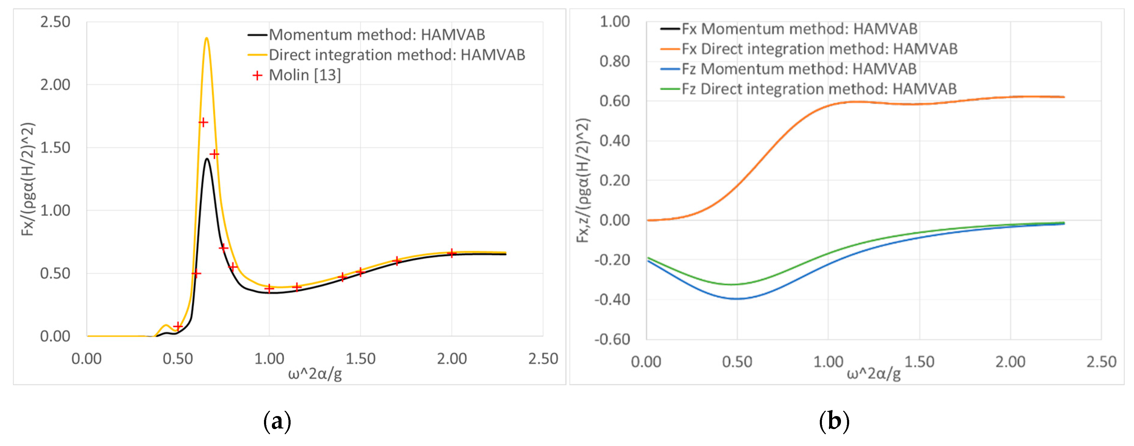
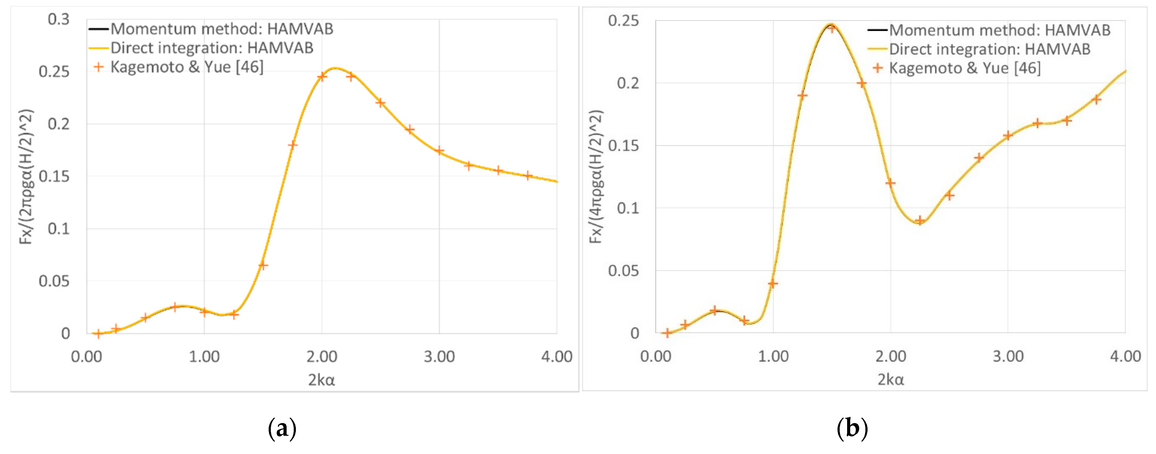
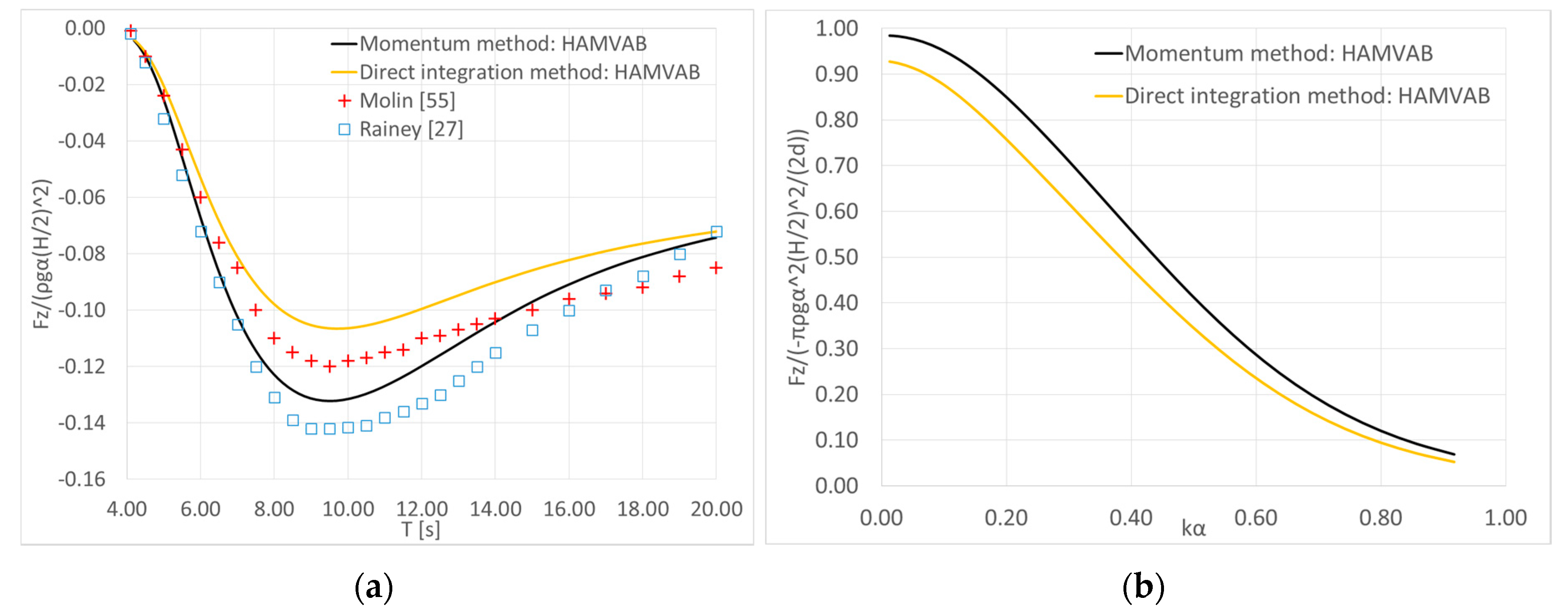
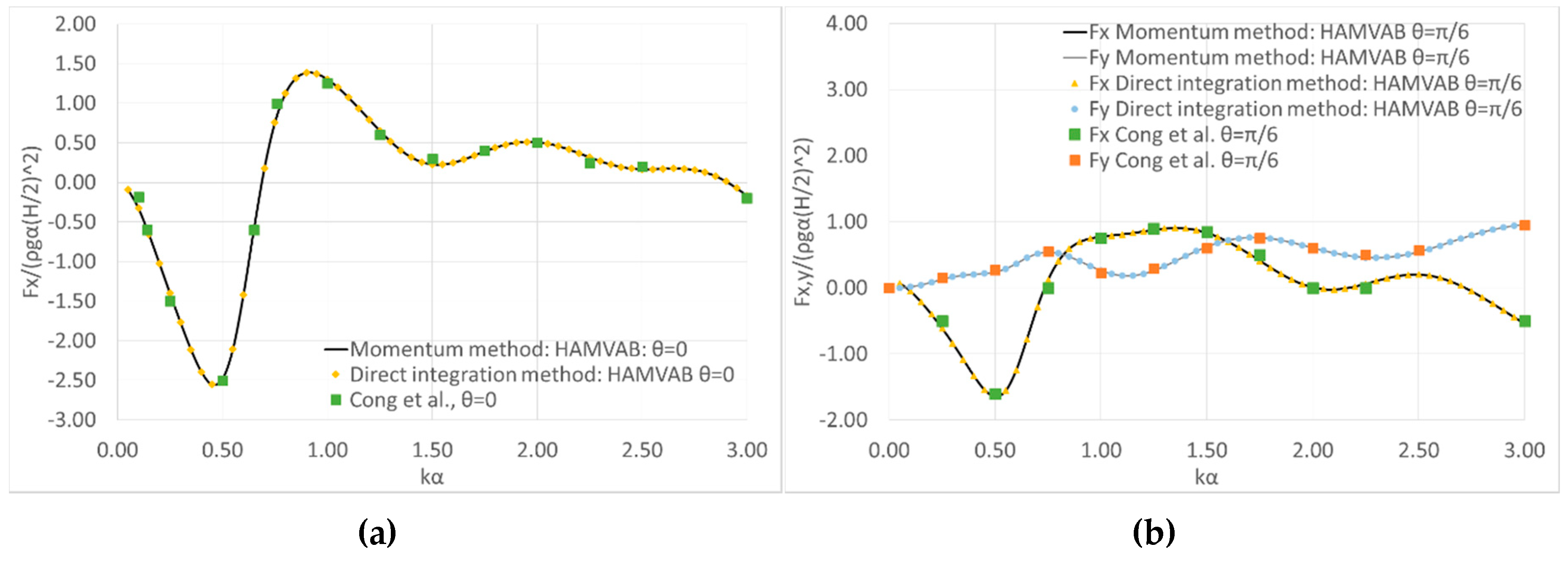
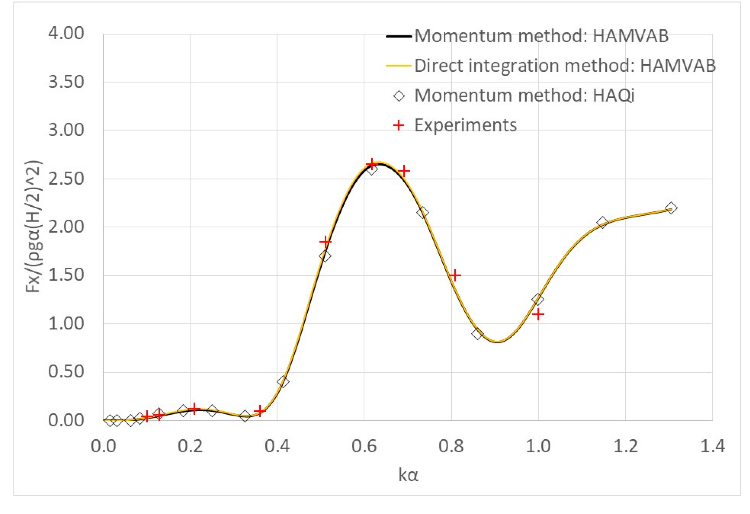
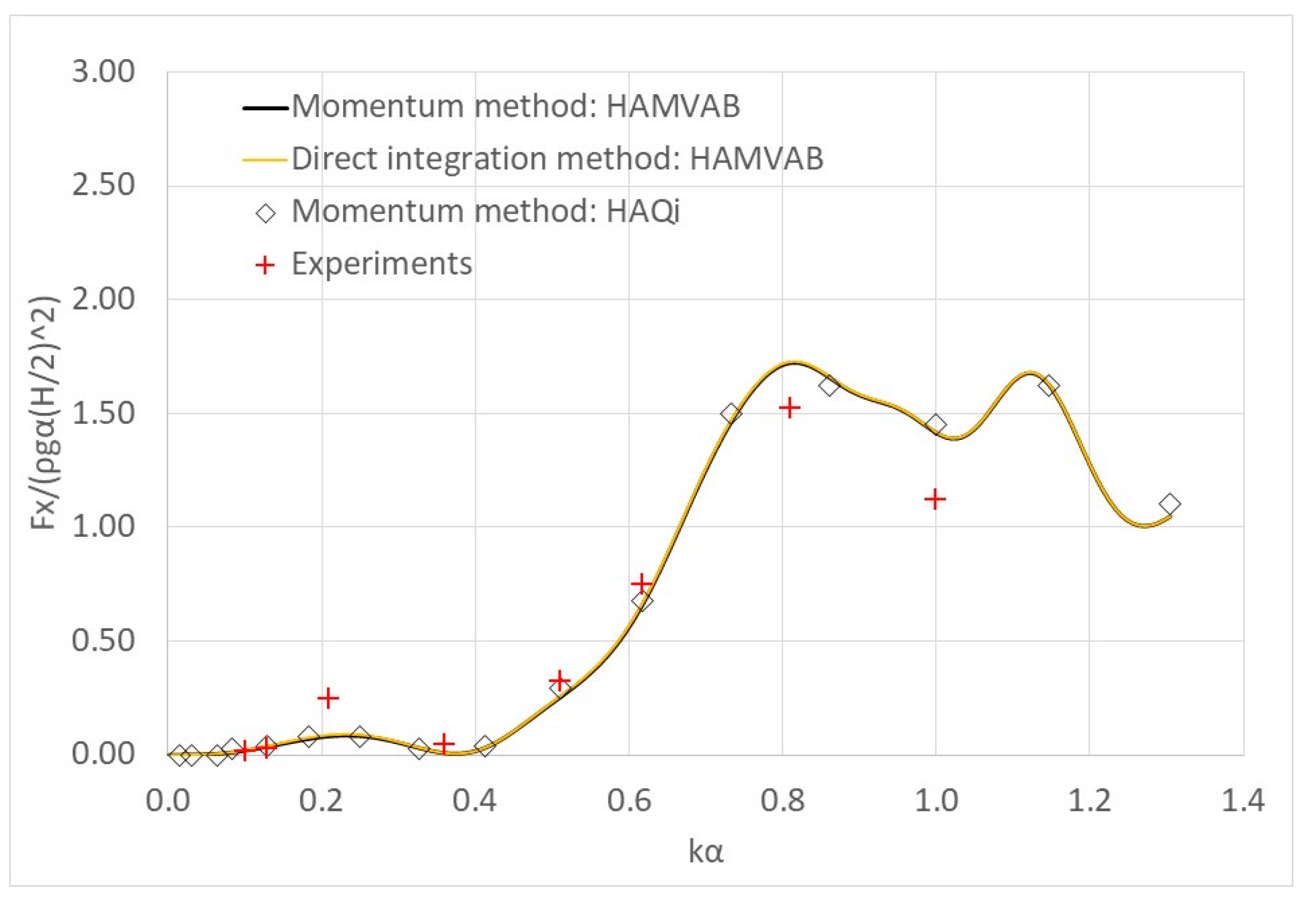
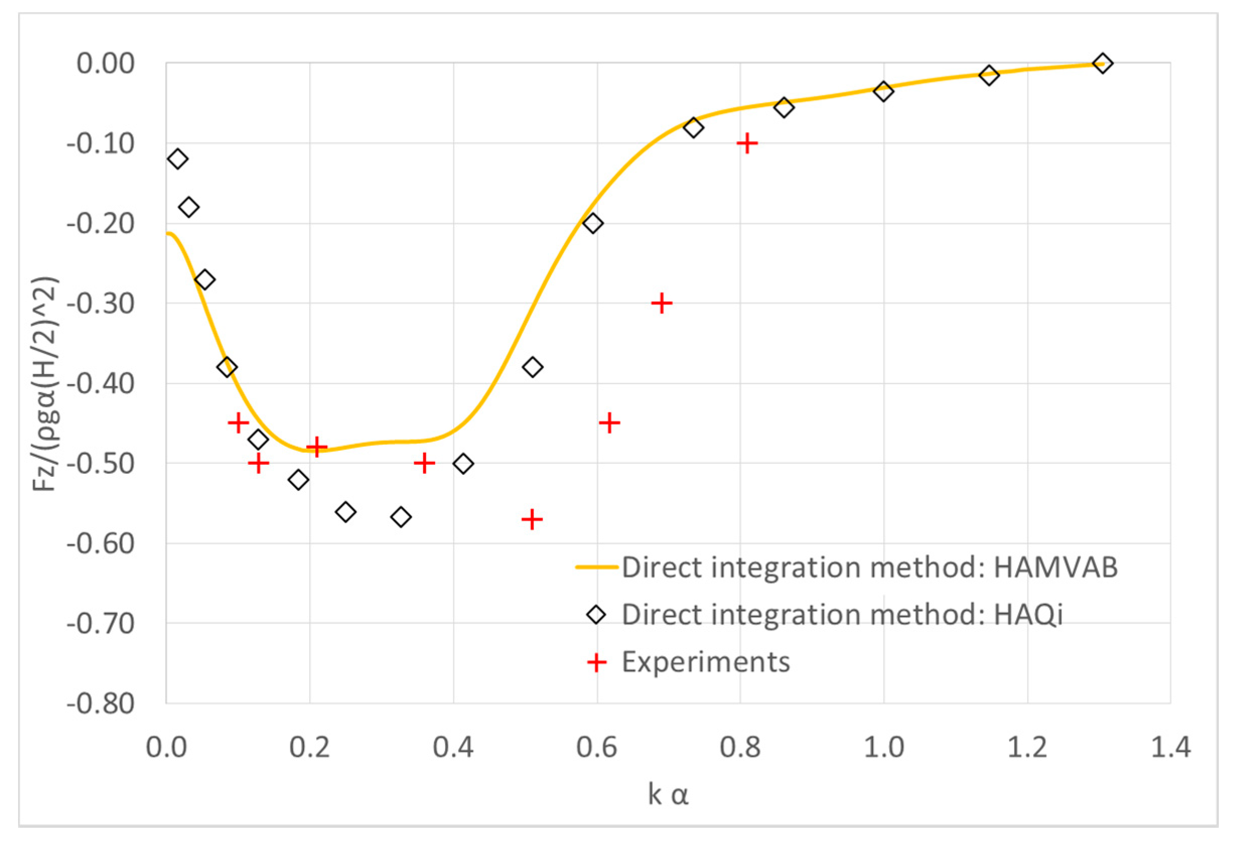
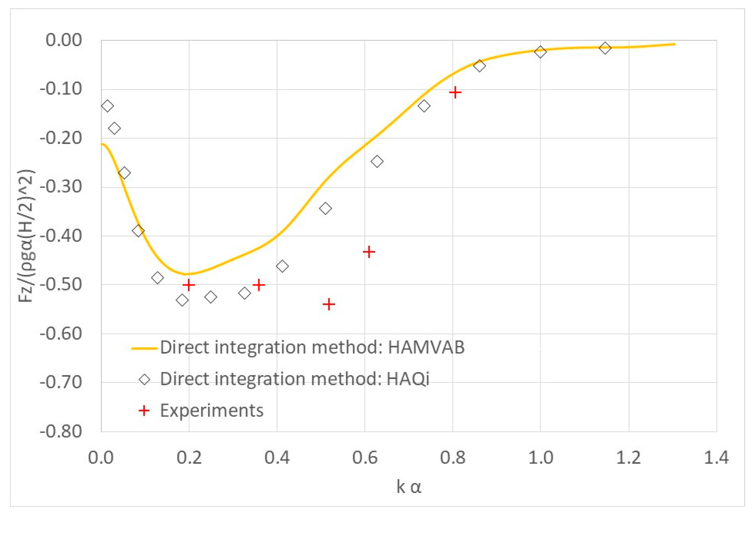
4. Results Validation

This section is dedicated to confirm the validity of the presented methods and their computer implementation. Thus, a number of configurations have been examined concerning the horizontal and vertical mean drift forces. The presented theoretical results were obtained from the theoretical software HAMVAB [54], using both computation methods (momentum and direct integration methods).
In Figure 2a,b, theoretical results for the mean drift forces on a floating truncated cylinder, first studied in Reference [13], are presented. The results that were obtained using both computational methods, i.e., near and far- field, were plotted against the dimensionless parameter ω2α/g. The examined cylinder had a draft to radius ratio (d − h)/α, equal to 1, floating in a water depth d = 7.14 α. The center of gravity lay at 0.485 α above the keel line and the radius of gyration was 0.742 α. In Reference [13], the horizontal mean drift forces on a floating cylinder, with the above characteristics are presented, and they were supplemented here with the horizontal and vertical mean drift forces of the same body, but restrained to the wave impact condition.
It can be seen from Figure 2a that, for the horizontal drift force, a good agreement was obtained with the two methods and the results from Reference [13]. Furthermore, for the restrained case (see Figure 2b), it can be seen that the horizontal forces given by both the methods always compared very well with each other. This is, however, not the case for the vertical drift forces, where the two methods depicted differences. These differences were more pronounced at small wave frequencies, whereas, for larger wave frequencies, both the methods attained similar results. It can be seen that the results from the direct integration method seem to attain, in general, higher values than the corresponding results from the momentum principle.
Geometries consisting of two and four truncated cylinders are examined in Figure 3a,b, respectively. In both configurations, the cylinders were floating in a water depth of d/α = 4, with draught (d − h)/α = 2. In the two-cylinder configuration, their distance ratio was selected to be Lk/α = 1.33; whereas, in the four-cylinder configuration, the bodies were arranged with their centers at the vertices of a square with Lk/α = 4. The mean horizontal drift forces on the group of the cylinders (i.e., two- and four- cylinder configuration), considered as a unit, were presented together with the corresponding results from Reference [46]. The results were non-dimensional by the factor (Νπρgα(H/2)2), where N denotes the number of the examined bodies, i.e., N = 2, 4. An excellent correlation of both computation methods and of the results from Reference [46] was depicted, for both cylinder configurations (i.e., two and four- cylinder).
In Figure 4, the vertical mean drift forces on a vertical cylinder, restrained in the wave impact, were plotted. In Figure 4a, the vertical forces acting on a cylinder of radius α = 4 m and draught (dh) = 12 m, were presented for an infinite water depth. The drift forces were normalized by ρgα(H/2)2. The results of both computation methods (momentum and direct integration method) were compared with the corresponding ones from References [55] and [27]. In Figure 4b, the same cylinder (i.e., α = 4 m) having, however, draught (dh) = 10 m, in water depth d = 25 m, was examined. The results (i.e., vertical mean drift forces) were normalized by (−πρgα2(H/2)2/(2d)).
In Figure 4a, the discrepancies between the vertical drift computation methods were notable. The theoretical results from the present analysis (near and far- field method) were, in general, in good agreement with the results from References [27] and [55]. It can also be seen that the lower values of the direct integration method than the corresponding resulted from the momentum principle. A similar conclusion can be drawn from Figure 4b concerning the discrepancies between the two methods. These discrepancies were more pronounced at lower wave frequencies, whereas, both methods converged for large wave frequencies.
The effect on the drift forces of a vertical breakwater placed behind a bottom seated vertical cylinder was presented in Figure 5. Herein, the vertical cylinder had a radius α, draught d = 5 α and the distance between the body and the vertical wall equals to 2 α. Two wave heading angles were examined, i.e., θ = 0, π/6. The presented horizontal drift forces were normalized by the factor ρgα(H/2)2. The presented results from both computation methods (i.e., momentum and direct integration method) compared excellently with the outcomes from Reference [56].

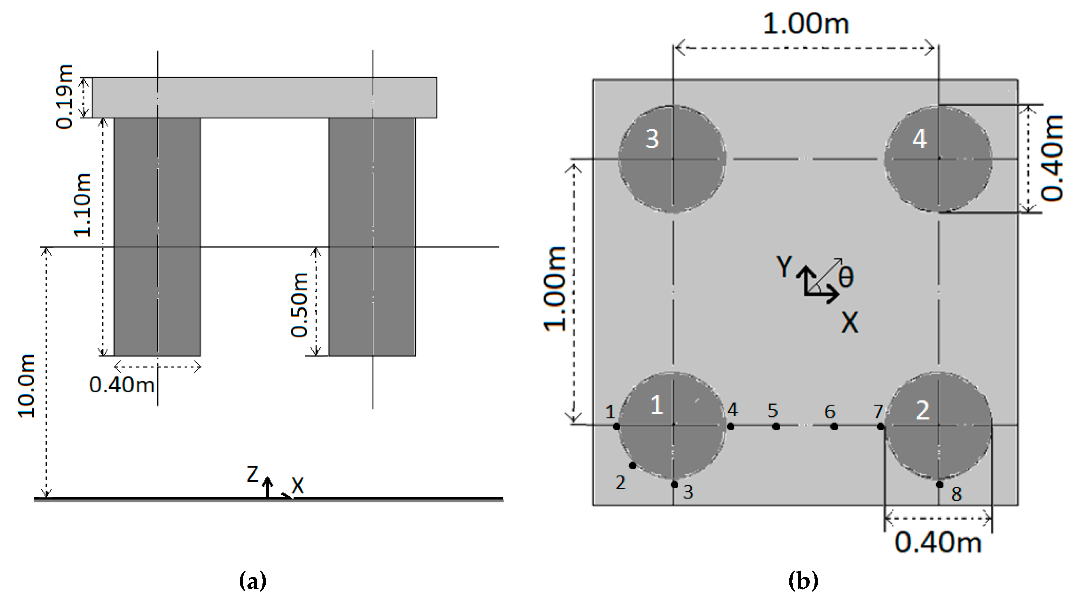
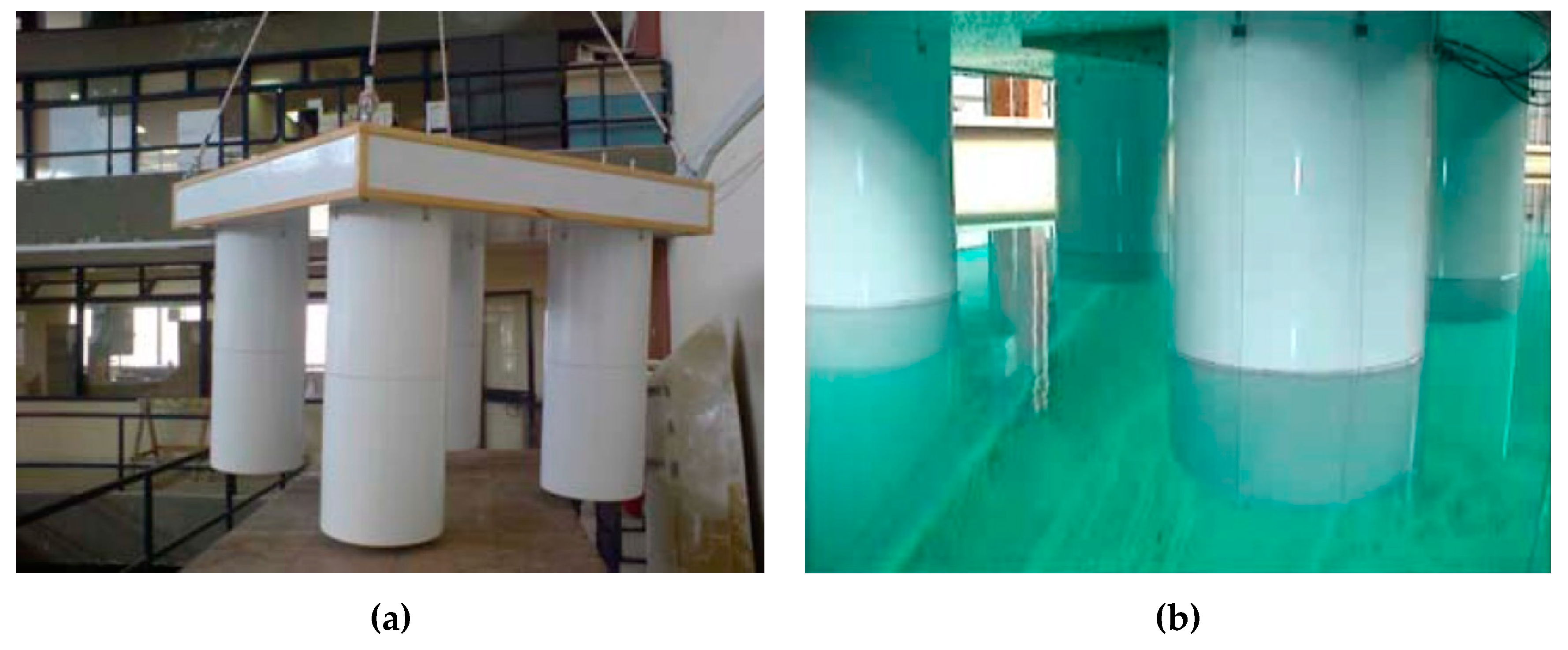
5. Experimental Campaign

In the framework of the present work, representative results from an experimental campaign that was carried out in the IFREMER model basin in France are given. The basin, which had a 50 m length, 12.5 m width and 10 m depth, was equipped with a wave maker producing for the specific tests a wide range of incident harmonic waves, whereas, on the opposite side, there is a wave absorbing beach. The physical model, with a scale of 1:100, consisted of a four vertical cylinder configuration that was attached on the tank’s main carriage. The geometric characteristics of the model are shown in Table 1 and in Figure 6. Figure 7a,b depict the model configuration outside and inside the wave tank, respectively. A series of mono-chromatic wave tests were carried out, assuming the configuration restrained in the wave impact, for two wave heading angles, i.e., θ = 0ο, 45ο. The amplitudes of the waves generated by the wave maker were measured by two-wave probes, one near the wave maker and the other in front of the model. During the experiments, a dynamometer was attached between the model and the carriage, at the model’s center of gravity, whereas, the wave elevation was being measured in eight points (i.e., four on the 1st vertical column, at 0°, 45°, 90°, 180°; two on the 2nd vertical column, at 0° and 90°; and two between the two vertical cylinders—see Figure 6b).
In Figure 8, Figure 9, Figure 10 and Figure 11, the total horizontal and vertical mean drift forces on the configuration are presented. The forces have been calculated theoretically, numerically and experimentally. The results obtained from the theoretical software HAMVAB, using both computation methods (momentum and direct integration method), and the numerical panel code HAQi [57], using the sink-source technique, are presented and compared against the corresponding experimental ones for wave heading angles of 0° and 45°. A total of 217 elements have been used for the discretization of each body’s wetted surface. Herein, the presented drift forces are non-dimensional by the factor ρgα(H/2)2 and plotted versus kα. Detailed presentation of the experimental results concerning the exciting wave forces; wave elevations and horizontal mean second order wave drift force at various forward speeds, as well as comparisons with theoretical and numerical outcomes are presented in [58].
In Figure 8 and Figure 9, the total horizontal mean drift forces on the configuration are presented for θ = 0° and 45°, respectively. It can be seen that the theoretical results from both computational methods (i.e., near field and far field method) and the numerical results, derived from the far-field method, compare very well. Furthermore, a very good comparison between the numerical/theoretical results with the experimental data can be reported. The presented results verify the discussion in Section 4 concerning the appearance of negligible discrepancies between the two computational methods for the horizontal mean drift forces on restrained bodies.
In Figure 10 and Figure 11, the total vertical mean drift forces on the configuration are presented for θ = 0° and 45°, respectively. While the agreement between the theoretically/numerically predicted values and their measured counterparts is not as fair as in the case of the horizontal drift forces (see Figure 8 and Figure 9), it should be mentioned that the trend of the results is the same. Here, the vertical drift forces have been evaluated using the direct integration method. Some discrepancies of the results between the analytical and the numerical methodologies, especially at small wave numbers, are depicted. These discrepancies are becoming less pronounced for large wave numbers where the two methods attain similar results.

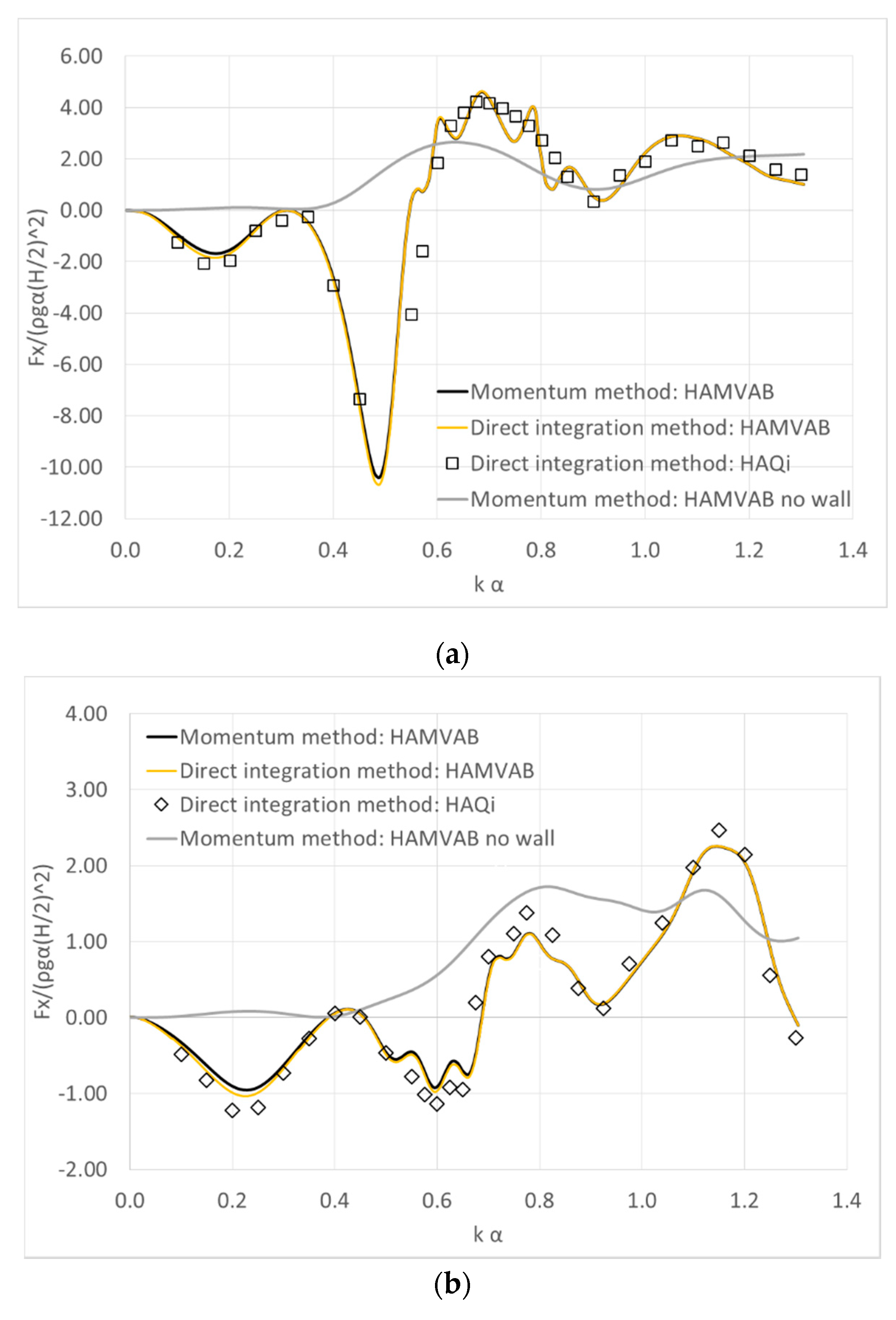
6. Array of Cylinders in Front of a Breakwater

In this section, the above-examined array of four cylindrical bodies is assumed to be placed in front of a vertical breakwater. The layout of the cylinder array has been shown in Figure 6, whereas the vertical wall is assumed to be placed on the right side of the array along the y, z axes. The effect of the vertical wall on the mean drift forces acting on the bodies is depicted in the figures below.
Figure 12a,b depict the total dimensionless horizontal drift forces acting on the array configuration, placed in front of the breakwater, normalized by the factor ρgα(H/2)2, for θ = 0° and 45°, respectively. Both computation methods are applied (i.e., momentum and direct integration methodology) using the method of images (i.e., infinite wall-length assumption). Herein, the distance between the closest to the wall floaters and the breakwater is equal to Lwk = 0.5 m. The presented results are also compared with the ones from the no wall case presenting, indicatively, the results from the momentum method (see Section 5), as well as with the numerical results from the direct integration method, derived from the HAQi software. For the latter software, an additional 528 elements are used for the breakwater simulation (for the simulation of the four bodies 868 elements have been used, see Section 5). Furthermore, for the numerical analysis, the breakwater is assumed to be rectangular, bottom fixed, surface piercing, solid body and having a length equal to 20 m (i.e., 100α, where α is the radius of each body).
It is evident from Figure 12a,b that the presence of the vertical wall affects the total mean drift forces on the configuration at every examined wave number, irrespective of the examined wave heading angle, since the forces’ values do not follow the smooth pattern as in the no wall-case-results. More specifically, due to the reflected waves from the breakwater, the values of the mean drift forces experience significant oscillations around the corresponding values without the presence of the wall. Furthermore, it can be seen that the results referred to both theoretical computation methods (i.e., near and far-field method) are similar, regardless the wave heading angle. As far as the numerical results and their comparisons with the theoretical ones are concerned, a very good correlation appeared. It is worth noting, however, some discrepancies between the results of the finite and infinite-wall case at 0.6 < kα < 0.8 for θ = 0°. The assumption of a fully reflecting wall of infinite length, in the image method, leads to significant peaks and troughs of the values of the mean drift forces at these wave numbers. This can be explained on basis of the distance between the initial and the image bodies in relation to the wave length. At this wave number band, the value of the corresponding wave length is close to 2 m for the examined configuration, i.e., which is equals to twice the distance between the initial and the image arrangement, causing this peculiar behavior. This behavior does not appear at the finite wall case, since no image bodies are considered.
The effect of the distance between the vertical wall and the four-body arrangement on the horizontal mean drift forces is presented in the below figures. Several distances between the two close-to-wall cylinders and the vertical wall are examined, i.e., Lwk = 2.5 α, 7.5 α, 12.5 α, (where α is the radius of each body in the array, i.e., α = 0.2 m), for wave heading angles θ = 0°, 45°. Figure 13 and Figure 14 present the horizontal mean drift forces acting on the array of bodies in front of the breakwater, for θ = 0° and 45°, respectively. The presented results, derived by the two computation methods (i.e., momentum and direct integration method), are normalized by the factor ρgα(H/2)2.
It is clear from Figure 13 and Figure 14a,b that the distance between the body-arrangement and the vertical wall affects the mean drift forces on the configuration since the forces’ values do not follow the same pattern as in the no wall case (see Figure 11 and Figure 12). Concerning the surge mean drift forces on the arrangement (i.e., Figure 13 and Figure 14a), it can be seen that as the distance of the bodies from the vertical wall increases, the earlier (i.e., at small wave numbers) the oscillatory behavior of the forces occur. In addition, it’s depicted that the forces’ zeroing at several wave numbers, regardless the examined wave heading angle. This behavior, however, does not appear in the no wall case. The zeroing of the surge mean drift forces can be traced back to the interaction phenomena between the arrangement and the vertical wall. As far as the sway mean drift forces are concerned (see Figure 14b), it is noted that the larger the distance between the bodies and the wall is, the earlier and more pronounced are the oscillations of the drift forces values. Furthermore, in compliance with the no-wall case, both drift forces computation methods attain similar results, regardless of the wave heading angle or the distance between the bodies from the wall.

7. Conclusions

The interaction phenomena between an array of floating cylindrical bodies and a vertical breakwater, and their effect on the mean drift forces, is studied. A theoretical and a numerical model has been presented, i.e., matched axisymmetric eigenfunctions expansion formulation and sink-source technique, respectively. As far as the calculation of the drift forces is concerned, two computation methods have been analyzed. The first one is based on the momentum conservation principle, while the second one is based on the direct integration of the hydrodynamic pressure on the instantaneous wetted surface of the body. Based on the presented theoretical and numerical methods, systematic calculations have been performed for an array of four cylindrical bodies, either alone in the wave field or placed in front of a vertical breakwater. The numerical and the theoretical results have been supplemented with the experimental outcomes for two wave heading angles.
The main findings of the present research contributions that concerned the effect of the breakwater on the mean drift forces, which should not be neglected when designing a multi-column floating structure in front of a vertical wall. This effect, the significance of which depends on the distances between the bodies from the wall, as well as the wave heading angle, causes an amplification of the mean drift forces acting on the bodies at specific wave numbers.
Concerning the accuracy of the theoretical and numerical models, the presented figures showed that both models are attaining a very good correlation, and regardless of the examined configuration, the wave heading angle or the examined wave frequency. This is also the case for the horizontal drift forces on a restrained to the wave impact floating structure, where the results from the momentum conservation principle and the ones from the direct integration coincides very well with each other. However, non-negligible discrepancies of the vertical drift forces between the two computation methods are notable for the arrays of bodies.
Nevertheless, the present research will be continued further by examining the effect of a vertical wall on the drift forces of arbitrary shaped bodies as well as by applying the middle field method for the calculation of the drift forces to examine the result convergence.

Author Contributions

Conceptualization, S.M. and D.K.; methodology, S.M.; software, S.M. and D.K.; validation, S.M. and D.K.; investigation, S.M.; writing—original draft preparation, D.K.; writing—review and editing, S.M.; visualization, D.K.; supervision, S.M. All authors have read and agreed to the published version of the manuscript.

Funding

This research received no external funding.

Acknowledgments

The experimental campaign was conducted at IFREMER Research Institute, France, in the framework of a project entitled “Wave—Current Interaction with Vertical Cylinders“ supported by the European program “METRI-2” (“Marine Environment Tests and Research Infrastructure-2”, Contract N° 06/1216059/BF). This support is greatly appreciated.

Conflicts of Interest

The authors declare no conflict of interest.

Nomenclature

NNumber of bodies
dWater depth
hkDistance from the sea bed of the k body
αRadius of the examined body
ωWave frequency
kWave number
H/2Wave amplitude
θWave heading angle
rkk,zkLocal co-ordinate system of the k body
LkDistance between adjacent bodies
LwkDistance between the closest to the wall bodies from the breakwater
ΦTime harmonic complex velocity potential
φ 0 Velocity potential of the undisturbed incident harmonic wave
φ s k Scattered velocity potential for the k body
φ j k p Radiation velocity potential resulting from the forced p body motion
φ D k Diffraction velocity potential for the k body
ΩFluid domain
SFUndisturbed free water surface
SBSea bottom surface
S k Mean wetted surface of the k body
n k Unit normal vector
δk,pKronecker’s symbol
x j 0 k Amplitude of the translation and rotation motion of the k body
Ψ D , m k Unknown diffraction coefficient
Ψ j , m k p Unknown motion radiation coefficient
IThe infinite ring element around the k body
IIThe ring element below the k body
QjSingularity strength
GGreen function
xk,yk,zk,ξ,n,ζRectangular coordinates of the k body
PNumber of plane elements
p k Fluid pressure on the k body
V k Finite control volume of the k body
ρWater density
PLinear momentum of the fluid in the control volume
gGravity acceleration
UVelocity of the boundary surface
ζWave elevation
F k ¯ Mean second order drift forces
S R 0 Time dependent part of the vertical control surface
C R 0 Contour of the intersection of S R 0 with the (x,y) plane
C 0 Static water line
MGeneralized mass matrix
X k Vector of the first order translation
R Rotational transformation matrix
X ¨ g k Vector of the first order translational acceleration of body’s center of gravity
ζkRelative wave elevation of first order
X G 3 0 Vertical distance of the center of gravity from the sea bed

Appendix A

An array of N cylindrical bodies placed in front of a vertical breakwater is assumed to float independently in 6 degrees of freedom. The system of motion equations in the frequency domain can be written as:
p = 1 N j = 1 6 ( δ p . q m k j q + a k j q p ) x ¨ j 0 p + b k j q p x ˙ j 0 p + δ p . q c k j q x j 0 p = f k q ,   k = 1 , 2 , 6
In Equation (A1) the m k j q term denotes the mass matrix of the q body of the array; the c k j q term denotes the q body’s hydrostatic restoring stiffness; and the x j 0 p term the six-degree displacement vector of the p body. Furthermore, the term   δ p . q is Kronecker’s symbol.
The exciting forces on the q body, denoted as f k q , when the latter is part of an array of bodies placed in front of a breakwater can be determined by summing properly the exciting forces on the examined body q for two wave trains of angles θ and 180-θ [41]. In addition, the q body’s hydrodynamic mass and damping matrices, denoted as a k j q p and b k j q p , can be derived by summing the corresponding hydrodynamic characteristics of the q body due to the motions of the p body with the corresponding characteristics of the q body due to the motions of the p body’s image solid [41].

References

  1. Havelock, T.H. The pressure of water waves upon a fixed obstacle. In Proceedings of the Royal Society of London; Series A, Mathematical and Physical Sciences; Royal Society: London, UK, 1940; Volume 175, pp. 409–421. [Google Scholar]
  2. Emmerhoff, O.J.; Sclavounos, P.D. The simulation of slow-drift motions of offshore structures. Appl. Ocean Res. 1996, 18, 55–64. [Google Scholar] [CrossRef]
  3. Martin, J.; Kuo, C. Calculations for the steady tilt of semi-submersibles in regular waves. Trans. RINA 1979, 121, 87–101. [Google Scholar]
  4. Hineno, M.; Takegawa, H.; Oda, T.; Abe, M. The effect of low frequency roll motion on under-deck clearance of a semi-submersible platform. In Proceedings of the 2nd International Conference on Stability of Ships and Ocean Vehicles, Tokyo, Japan, 24–29 October 1982. [Google Scholar]
  5. Stansberg, C.T. Slow-drift pitch motions and air-gap observed from model testing with moored semi-submersibles. In Proceedings of the 26th International Conference on Ocean, Offshore and Arctic Engineering (OMAE), San Diego, CA, USA, 10–15 June 2007; Volume 1. [Google Scholar]
  6. Van der Valk, C.A.C.; Watson, A. Mooring OF LNG carriers to a weathervaning floater—Side-by-side or stern-by-bow. In Proceedings of the 2005 Offshore Technology Conference, Houston, TX, USA, 2–5 May 2005; p. 17154. [Google Scholar]
  7. Newman, J.N. Second order, slowly varying forces on vessels in irregular waves. In Proceedings of the International Symposium on Dynamics of Marine Vehicles and Structures in Waves, London, UK, 1–5 April 1974; pp. 182–186. [Google Scholar]
  8. Maruo, H. The drift of a body floating in waves. J. Ship Res. 1960, 4, 1–10. [Google Scholar]
  9. Newman, J.N. The drift force and moment on ships in waves. J. Ship Res. 1967, 11, 51–60. [Google Scholar]
  10. Faltinsen, O.M.; Michelsen, F.C. Motions of large structures in waves at zero Froude number. In Proceedings of the International Symposium on Dynamics of Marine Vehicles and Structures in Waves, London, UK, 1–5 April 1974; pp. 91–106. [Google Scholar]
  11. Lee, C.M.; Newman, J.N. The vertical man force and moment of submerged bodies under waves. J. Ship Res. 1971, 15, 231–245. [Google Scholar]
  12. Sclavounos, P.D. The Vertical Wave Drift Force on Floating Bodies. In Proceedings of the 2nd International Workshop on Water Waves and Floating Bodies, Bristol, UK, 16–19 March 1987. [Google Scholar]
  13. Molin, B. On second-order motion and vertical drift forces for three-dimensional bodies in regular waves. In Proceedings of the International Workshop on Ship and Platform Motion, Berkeley, CA, USA, 26–28 October 1983; pp. 344–357. [Google Scholar]
  14. Mavrakos, S.A. The vertical drift force and pitch moment on axisymmetric bodies in regular waves. Appl. Ocean Res. 1988, 10, 207–218. [Google Scholar] [CrossRef]
  15. Mavrakos, S.A. Mean drift loads on multiple vertical axisymmetric bodies in regular waves. In Proceedings of the 5th International Offshore and Polar Engineering Conference, The Hague, The Netherlands, 11–16 June 1995. [Google Scholar]
  16. Kashiwagi, M. Added resistance, wave-induced steady sway force and yaw moment on an advancing ship. J. Schiffstechnik 1992, 39, 3–16. [Google Scholar]
  17. Kashiwagi, M.; Ohkusu, M. Study on the wave-induced steady force and moment. J. Soc. Nav. Archit. Jpn. 1993, 173, 185–194. [Google Scholar] [CrossRef]
  18. Pinkster, J.A.; Van Oortmerssen, G. Computation of the first and second order wave forces on oscillating bodies in regular waves. In Proceedings of the 2nd International Conference on Numerical Ship Hydrodynamics, Berkeley, CA, USA, 19–21 September 1977. [Google Scholar]
  19. Standing, R.G.; Dacunha, N.M.C. Slowly-varying and mean second-order wave forces on ships and offshore structures. In Proceedings of the 14th Symposium on Naval Hydrodynamics, Ann Arbor, MI, USA, 23–27 August 1982; pp. 279–318. [Google Scholar]
  20. Papanikolaou, A.; Zaraphonitis, G. On the improved method for the evaluation of second-order motions and loads on 3D floating bodies in waves. J. Schiffstechnik 1987, 34, 170–211. [Google Scholar]
  21. Zhao, R.; Faltinsen, O.M. Interaction between current, waves and marine structures. In Proceedings of the 5th International Conference on Numerical Ship Hydrodynamics, Hiroshima, Japan, 24–28 September 1990. [Google Scholar]
  22. Shao, Y.L. Numerical analysis of second-order mean wave forces by a stabilized higher order boundary element method. In Proceedings of the 37th International Conference on Ocean, Offshore and Arctic Engineering, (OMAE), Madrid, Spain, 17–22 July 2018. [Google Scholar]
  23. Chen, X.B. Hydrodynamic analysis for offshore LNG terminals. In Proceedings of the 2nd Offshore Hydrodynamics Symposium, Rio de Janeiro, Brazil, 14–15 April 2005. [Google Scholar]
  24. Rezend, F.; Li, X.; Chen, X.-B. Second order loads on LNG terminals in multi-directional sea in water of finite depth. In Proceedings of the 26th International Conference on Ocean, Offshore and Arctic Engineering (OMAE), San Diego, CA, USA, 10–15 June 2007; Volume 1. [Google Scholar]
  25. Cong, P.; Liu, Y. Local Enhancements of the mean drift wave force on a vertical column shielded by an exterior thin porous shell. J. Mar. Sci. Eng. 2020, 8, 349. [Google Scholar] [CrossRef]
  26. Higo, Y.; Ha, M.K. A study on added resistance of a restrained body with forward speed in waves. J. Soc. Nav. Archit. Jpn. 1991, 169, 75–83. [Google Scholar] [CrossRef] [Green Version]
  27. Rainey, R.C.T. A new equation for calculating wave loads on offshore structures. J. Fluid Mech. 1989, 204, 295–324. [Google Scholar] [CrossRef]
  28. Kobayashi, M.; Shimada, K.; Fujchira, T. Study on the dynamic response of a TLP in waves. In Proceedings of the 4th International Offshore Mechanics and Arctic Engineering Symposium; ASME: New York, NY, USA, 1985; Volume 1, pp. 29–35. [Google Scholar]
  29. Kashiwagi, M.; Endo, K.; Yamaguchi, H. Wave drift forces and moments on two ships arranged side by side in waves. Ocean Eng. 2005, 32, 529–555. [Google Scholar] [CrossRef]
  30. Konispoliatis, D.; Mavrakos, S. Mean drift loads on arrays of free floating OWC devices consisting of concentric cylinders. In Proceedings of the 29th International Workshop on Water Waves and Floating Bodies, Osaka, Japan, 30 March–2 April 2014. [Google Scholar]
  31. Ikoma, T.; Maeda, H.; Rheem, C.-K. Slowly varying wave drifting force on a very large floating structure in short crested waves. In Proceedings of the OCEANS 2000 MTS/IEEE Conference and Exhibition, Providence, RI, USA, 11–14 September 2000; Volume 1, pp. 533–539. [Google Scholar]
  32. Liu, Y.N.; Molin, B.; Kimmoun, O.; Remy, F.; Rouault, M.C. Experimental and numerical study of the effect of variable bathymetry on the slow-drift wave response of floating bodies. Appl. Ocean Res. 2011, 33, 199–207. [Google Scholar] [CrossRef]
  33. Mavrakos, S.A.; Katsaounis, G.M.; Nielsen, K.; Lemonis, G. Numerical performance investigation of an array of heaving wave power converters in front of a vertical breakwater. In Proceedings of the 14th International Offshore and Polar Engineering Conference (ISOPE 2004), Toulon, France, 23–28 May 2004. [Google Scholar]
  34. Mavrakos, S.A.; Katsaounis, G.M.; Kladas, A.; Kimoulakis, N. Numerical and experimental investigation of performance of heaving WECs coupled with DC generators. In Proceedings of the 9th European Wave and Tidal Energy Conference, Southampton, UK, 5–9 September 2011. [Google Scholar]
  35. McIver, P.; Porter, R. The motion of a freely floating cylinder in the presence of a wall and the approximation of resonances. J. Fluid Mech. 2016, 795, 581–610. [Google Scholar] [CrossRef] [Green Version]
  36. Teng, B.; Ning, D.Z. Wave diffraction from a uniform cylinder in front of a vertical wall. Ocean Eng. 2003, 21, 48–52. [Google Scholar]
  37. Teng, B.; Ning, D.Z.; Zhang, X.T. Wave radiation by a uniform cylinder in front of a vertical wall. Ocean Eng. 2004, 31, 201–224. [Google Scholar] [CrossRef]
  38. Zheng, S.; Zhang, Y. Wave diffraction from a truncated cylinder in front of a vertical wall. Ocean Eng. 2015, 104, 329–343. [Google Scholar] [CrossRef]
  39. Zheng, S.; Zhang, Y. Wave radiation from a truncated cylinder in front of a vertical wall. Ocean Eng. 2016, 111, 602–614. [Google Scholar] [CrossRef]
  40. Konispoliatis, D.N.; Mavrakos, S.A. Theoretical performance investigation of a vertical cylindrical oscillating water column device in front of a vertical breakwater. J. Ocean Eng. Mar. Energy 2019, 6, 1–13. [Google Scholar] [CrossRef]
  41. Konispoliatis, D.N.; Mavrakos, S.A.; Katsaounis, G.M. Theoretical Evaluation of the Hydrodynamic Characteristics of Arrays of Vertical Axisymmetric Floaters of Arbitrary Shape in front of a Vertical Breakwater. J. Mar. Sci. Eng. 2020, 8, 62. [Google Scholar] [CrossRef] [Green Version]
  42. Loukogeorgaki, E.; Boufidi, I.; Chatjigeorgiou, I. Performance of an array of oblate spheroidal heaving wave energy converters in front of a wall. Water 2020, 12, 188. [Google Scholar] [CrossRef] [Green Version]
  43. Twersky, V. Multiple scattering of radiation by an arbitrary configuration of parallel cylinders. J. Acoust. Soc. Am. 1952, 24, 42–46. [Google Scholar] [CrossRef]
  44. Mavrakos, S.A.; Koumoutsakos, P. Hydrodynamic interaction among vertical axisymmetric bodies restrained in waves. Appl. Ocean Res. 1987, 9, 128–140. [Google Scholar] [CrossRef]
  45. Mavrakos, S.A. Hydrodynamic coefficients for groups of interacting vertical axisymmetric bodies. Ocean Eng. 1991, 18, 485–515. [Google Scholar] [CrossRef]
  46. Kagemoto, H.; Yue, D.K.P. Interactions among multiple three-dimensional bodies in water waves: An exact algebraic method. J. Fluid Mech. 1986, 166, 189–209. [Google Scholar] [CrossRef]
  47. Linton, C.M.; Evans, D.V. The interaction of waves with arrays of vertical circular cylinders. J. Fluid Mech. 1990, 215, 549–569. [Google Scholar] [CrossRef]
  48. Mavrakos, S.A.; McIver, P. Comparison of methods for computing hydrodynamic characteristics of arrays of wave power devices. Appl. Ocean Res. 1997, 19, 283–291. [Google Scholar] [CrossRef]
  49. Wehausen, J.V.; Laitone, E.V. Surface Waves. In Encyclopedia of Physics; Springer: Berlin/Heidelberg, Germany, 1960; Volume 9. [Google Scholar]
  50. Mavrakos, S.A.; Bardis, L. Hydrodynamic Characteristics of Large Offshore Units. In Proceedings of the 3rd International Congress on Marine Technology (IMAM), Athens, Greece, 28 May–1 June 1984; pp. 505–513. [Google Scholar]
  51. Garrison, C.J. Hydrodynamics of large objects in the sea. Part I: Hydrodynamic analysis. J. Hydronautics 1974, 8, 5–12. [Google Scholar] [CrossRef]
  52. Garrison, C.J. Hydrodynamics of large objects in the sea. Part II: Motion of free floating bodies. J. Hydronautics 1975, 9, 58–63. [Google Scholar] [CrossRef]
  53. Konispoliatis, D.N.; Mavrakos, S.A. Wave power absorption by arrays of wave energy converters in front of a vertical breakwater. A theoretical study. Energies 2020, 13, 1985. [Google Scholar] [CrossRef] [Green Version]
  54. Mavrakos, S.A. User’s Manual for the Computer Code HAMVAB; Laboratory for Floating Bodies and Mooring Systems, National Technical University of Athens: Athens, Greece, 2001. [Google Scholar]
  55. Molin, B.; Lacaze, J.B. On approximations of the wave drift forces acting on semi-submersible platforms with heave plates. In Proceedings of the 35th International Conference on Ocean, Offshore and Arctic Engineering, Busan, Korea, 19–24 June 2016. [Google Scholar]
  56. Cong, P.; Chen, L.; Gou, Y. Hydrodynamic interaction among multiple columns in front of a vertical wall. Ocean Eng. 2020, 197, 106877. [Google Scholar] [CrossRef]
  57. Bardis, L.; Mavrakos, S.A. User’s Manual for the Computer Code HAQ; Laboratory for Floating Bodies and Mooring Systems, National Technical University of Athens: Athens, Greece, 1988. [Google Scholar]
  58. Mavrakos, S.A.; Mazarakos, T.P.; Konispoliatis, D.N. First- and second- order hydrodynamic effects and wave run-up on a four cylinder configuration at small forward speed. In Proceedings of the 9th International Congress on Mechanics (HSTAM), Limassol, Cyprus, 12–14 July 2010. [Google Scholar]
Figure 1. 2-D and 3-D representations of a random array of N cylindrical bodies in front of a breakwater (image bodies are colored in dark grey assuming the absence of a breakwater): (a) 2-D plan view of the array; (b) 3-D side view of the k body and its image solid.
Fluids 05 00148 g001
Figure 2. Horizontal and vertical mean drift forces on a floating cylindrical body: (a) horizontal mean drift forces when the body is freely floating. The results are compared with the ones from Reference [13]; (b) horizontal and vertical mean drift forces when the body is assumed to be restrained in the wave impact.
Fluids 05 00148 g002
Figure 3. Horizontal mean drift forces on arrays of floating cylindrical bodies: (a) two-cylinder configuration; (b) four-cylinder configuration. The results are compared with the corresponding outcomes from Reference [46].
Fluids 05 00148 g003
Figure 4. Vertical mean drift forces on a vertical cylindrical body: (a) cylinder of radius α = 4m; draught (d − h) = 12 m; and infinite water depth. The results are compared with the corresponding outcomes from References [27,55]; (b) cylinder of radius α = 4m; draught (d − h) = 10 m; water depth d = 25 m.
Fluids 05 00148 g004
Figure 5. Horizontal mean drift forces on a vertical bottom seated cylinder in front of a vertical breakwater for several wave heading angles: (a) θ = 0; (b) θ = π/6. The results are compared with the corresponding outcomes from Reference [56].
Fluids 05 00148 g005
Figure 6. 2-D representations of the examined configuration of four cylindrical bodies: (a) side view; (b) plan view. The eight wave elevation measured locations are also depicted, colored in black.
Fluids 05 00148 g006
Figure 7. Photo of the examined configuration of four cylindrical bodies: (a) outside the wave tank; (b) inside the wave tank.
Fluids 05 00148 g007
Figure 8. Total horizontal mean drift forces on the configuration for θ = 0°. The theoretical results from both methods (momentum and direct integration methods) are plotted along with the numerical results from the far-field methodology and compared to the experimental ones.
Fluids 05 00148 g008
Figure 9. Total horizontal mean drift forces on the configuration for θ = 45°. The theoretical results from both methods (momentum and direct integration methods) are plotted along with the numerical results from the far-field methodology and compared to the experimental ones.
Fluids 05 00148 g009
Figure 10. Total vertical mean drift forces on the configuration for θ = 0°. The theoretical and the numerical results from the direct integration method are presented against the experimental ones.
Fluids 05 00148 g010
Figure 11. Total vertical mean drift forces on the configuration for θ = 45°. The theoretical and the numerical results from the direct integration method are presented against the experimental ones.
Fluids 05 00148 g011
Figure 12. Total horizontal mean drift forces on the configuration placed in front of a breakwater: (a) θ = 0°; (b) θ = 45°. The theoretical results from both methods (momentum and direct integration method) are compared against the numerical results from the direct integration methodology and the theoretical results from the no wall case.
Fluids 05 00148 g012
Figure 13. Total horizontal (surge) mean drift forces on the configuration placed at various distances in front of a vertical breakwater, for θ = 0°. The theoretical results from both methods (momentum and direct integration methods) are presented.
Fluids 05 00148 g013
Figure 14. Total horizontal mean drift forces on the configuration placed at various distances in front of a vertical breakwater, for θ = 45°, (a) in surge direction; (b) in sway direction. The theoretical results from both methods (momentum and direct integration methods) are presented.
Fluids 05 00148 g014
Table 1. Model characteristics.
Model CharacteristicsValue
Weight (kg)160.000
Displacement (kg)257.611
Cylinder draught (m)0.50
Cylinder height (m)1.10
Cylinder diameter (m)0.40
Distance between cylinders (m)1.00

