Abstract
Existing strategies for hydrocarbon extraction have been designed primarily based on macroscopic properties of fluids and rocks. However, recent work on tight formations and source rocks (such as shale) revealed that the fluid properties and phase change of the hydrocarbons stored in the lower end of the pore size distribution inside the organic nanopores deviate significantly from their bulk phases in the large pores. The cause for such deviations is primarily the presence of strong fluid-wall molecular interactions in the nanopore. Organic nanopores, in source rock, store more hydrocarbons than those pores in a conventional reservoir for the same pore volume because nanopore confined hydrocarbons are more compacted and denser than the bulk phase. However, the recovery factor from these pores were reported to be considerately lower. Surfactants, introduced in the form of micelle or microemulsion, have the potential to increase the recovery. Whereas the transport behavior of micelles and their adsorption on solid walls are well-established, the role of microemulsion on the recovery of hydrocarbons under confinement remains poorly understood. In this work, molecular dynamics (MD) simulations were employed to investigate the two-phase flow in kerogen nanopores containing oil, water, and a microemulsion droplet. A slit-shaped pore was modeled representing the organic nanopore, and a mixture of hydrocarbon was chosen to represent the oil phase. Initially, the microemulsion droplets containing nonionic surfactant dodecylhepta(oxyethylene)ether (C12E7), swollen with solvent (d-limonene), were introduced to the water phase. We showed that the droplets were dispersed under the strong molecular interactions existing in the nanopore space. Subsequently, both the solvent and the surfactant components played essential roles in displacing the oil phase. The surfactant molecules were deposited at the interface between the aqueous phase and the oil, thereby reducing the interfacial tension. The solvent molecules, originally solubilized in a microemulsion droplet, penetrated the oil film near the pore walls. Those solvent molecules were exchanged with the adsorbed oil molecules and transformed that portion of oil into free oil for enhanced recovery. In addition, we considered the Couette flow of water near the organic wall with a film of oil, and found that the oil phase, which consisted of free and adsorbed molecules, could be mobilized by the viscous force caused by the flowing water. Hence, the chemicals introduced by the water mobilized both the free oil and a portion of adsorbed oil inside the oil-wet pores. However, there existed a slip at the oil/water interface which inhibited the momentum transfer from the water phase to the oil phase. When the surfactants were present at the interface, they acted as a linker that diminished the slip at the interface, hence, allowing the momentum transfer from the water phase to the oil phase more effectively. As a result, the fractional flow of oil increased due to the presence of both the surfactant and the solvent. At the final part, we extended our study from a single channel to three-dimensional (3D) kerogen pore network, where the pore sizes were less than or equal to 7 nm. The MD results showed that the dispersed microemulsion droplets also mobilized and displaced the oil present within the kerogen pore network. The results of this work are important for our understanding of flow and displacement under confinement and its application to oil recovery from source rocks.
1. Introduction
Resource shale formations exploited for oil and gas production are clastic sedimentary rocks that are characteristically fine-grained, laminated, and fissile [1]. They are rich in organic matter [2,3]. During the burial and diagenesis processes, the deposited organic mass undergoes metamorphism and is converted into kerogen, solid state organic matter, which is insoluble in the organic solvents. Over a long maturation time, high pressure and temperature converts kerogen into hydrocarbon fluids such as oil and natural gas. The generation of hydrocarbon fluids from kerogen is referred to as the catagenesis. Thermal maturity defines the degree to which the source rock has been exposed to a high heat environment which is needed to convert kerogen into hydrocarbons [4]. Different degrees of maturity are responsible for varying kerogen properties and different hydrocarbon compositions of produced fossil fuels. During the processes of burial, diagenesis and hydrocarbon generation, a complex multiscale pore structure develops including the kerogen pores, inorganic (clayey) matrix pores and microcracks, and natural fractures, which permit oil and gas transport in the formation [3].
Several studies have recently focused on the understanding of geological structure and mineral composition of reservoir rocks, as well as the molecular structure of kerogen. The latter has been investigated by a number of experimental techniques, such as solid state nuclear magnetic resonance (13C NMR) and X-ray photoelectron spectroscopy [5,6,7]. For example, elemental analysis performed on Type 1 kerogen from the Green River Shale Formation in Northwestern USA indicated the following proportions of major constituting elements: carbon 215, hydrogen 330, oxygen 12, nitrogen 5, and sulfur 1 [8,9]. Typical average pore size in the kerogen was just a few nanometers [10]. Scanning electron microscopy images indicated organic and inorganic pores in the shale matrix. It was reported that organic-rich shale samples with kerogen pore volume can make more than 20% of the total shale pore volume [2,11]. Hence, kerogen could significantly contribute to the storage of hydrocarbons in resource shales, but the small sizes of its pores can severely limit fluid transport [12,13,14]. The kerogen pore network has features that cover multiple dimensions, extending over several orders of magnitude. In large pores and microcracks, one would anticipate that the existing theory of multiphase multicomponent flow prevails. Thus, factors controlling the microscopic recovery efficiency are expected to be the same, i.e., wettability, interfacial tension (IFT), relative permeability, and capillary pressure. During the hydraulic fracturing and shut-in periods, invasion of the fracturing water into the matrix, and the subsequent adsorption of the injected chemicals take place at the oil/water interfaces and at the solid surfaces. Placement of the chemicals causes reduction in the IFT and alterations in wettability of the matrix surfaces, respectively, as well as in the redistribution of introduced chemicals between the different interfaces. This could lead to a reduced capillary pressure, and hence mobilization of the oil phase. If the chemical treatment contains a solvent, such as that present in microemulsions, additional mobilization of oil can be associated with the adsorption of the solvents.
The mechanisms by which microemulsion additives improve the hydrocarbon production are not yet fully understood. In earlier studies [15,16,17], it was suggested that, due to the presence of solubilized terpene solvent, the surfactant adsorption to the rock was minimized, while a recent and more in-depth study [18] indicated that the extent of surfactant adsorption depended on the microemulsion composition in a complex manner. In addition to the solubilized terpene solvent, microemulsion additives also contain surfactants, which are the main carriers of the surface activity. Surfactants have a long history of use in the petroleum industry. In enhanced oil recovery, production is influenced by the ability of injected surfactants on the IFT at the oil/water interfaces and to promote wetting conditions under which the water phase would readily displace the oil phase. While changes in the wettability can be achieved by surfactant adsorption, the excessive adsorption reduces the effectiveness of a surfactant in lowering the IFT [19]. The adsorption of nonionic surfactants on nonpolar surfaces makes the surface hydrophilic, more water-wet, and results in the displacement of oil from the vicinity of the solid surface [20].
The present study investigates the role of surfactants and the solubilized terpene solvent on the interactions with the oil in an organic material with a nanoscale pore network by conducting a molecular dynamics simulation. The source rocks are often rich in organic matter and research is needed to understand the microemulsion behavior in this environment. Aqueous phase microemulsion solution interacting with an oil phase by the organic walls is studied and the fundamental questions related to mobilization of the oil are raised. The oil mobilization using microemulsions could be considered in the following three consecutive stages: (i) delivery of the microemulsion droplets to the organic capillaries, (ii) breakup of the microemulsion droplet and distribution of the droplet components, and (iii) modification of the surface and transport properties. Here, we make the implicit assumption that the first stage has been completed, and hence the focus is on the second and third stages.
In this paper we first present a molecular simulation approach for modeling the fluids and the organic capillary. We discuss in detail the setup of the numerical simulation model and the nature of the data analyzed. Preliminary simulations of the aqueous phase are performed under thermodynamic equilibrium to show the presence of microemulsion droplets in the water phase, and to discuss the droplet characteristics and the droplet behavior as part of the aqueous phase bulk fluid. This bulk fluid represents the fracturing fluid used during hydraulic fracturing. Then, nonequilibrium molecular dynamics simulations are performed to investigate multiphase (oil/water) flow in the capillary. The Couette flow of oil by the organic wall is considered to develop laminar flow of oil of nearby water phase. In the presence of microemulsion droplets, the chemicals that make up the droplet have separate roles in mobilizing the oil phase. Due to the presence of solvent molecules, a significant increase in the fractional oil flow is predicted as compared with that of the surfactant only. The mechanisms for the oil mobilization are identified. In a previous study [18], the setup for Couette flow by the capillary wall utilized a perfectly flat surface with Steele potential [21] and we observed a slip of fluid velocity by the capillary wall. In this work, a more realistic rough kerogen surface is used for the Couette flow investigation. Finally, we extended our study from a single channel to three-dimensional (3D) porous kerogen network. The results showed that microemulsion in the aqueous phase mobilize the oil phase in the kerogen where the pores with sizes less than 10 nm. The results from the 3D kerogen pore network confirms that both the surfactant and the injected solvent have their own individual effects on the mobilization of the oil molecules and contribute to the oil recovery.
2. Computational Methodology
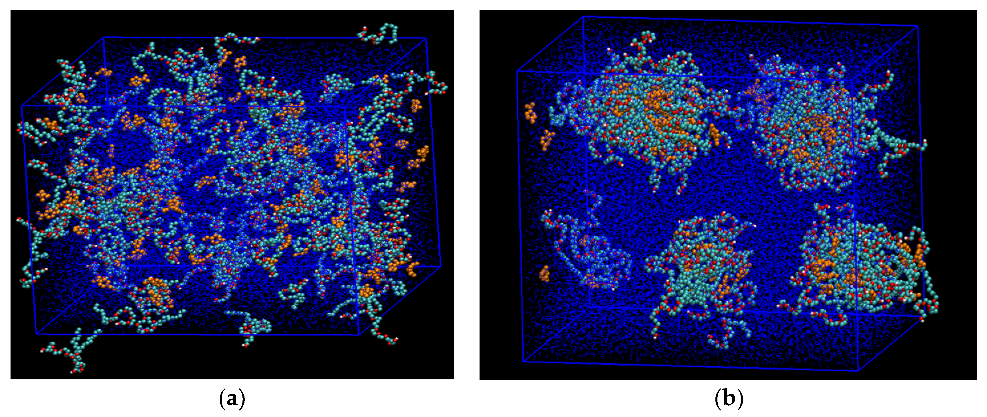
Molecular dynamics (MD) simulations were performed using GROMACS v5.1 package with GPU acceleration [22,23]. The Visual Molecular Dynamics (VMD), package was used for visualization of the simulation snapshots [24]. GROMOS 54a7 force field and Lorentz–Berthelot mixing rule were chosen to model the interaction between the molecules [25,26]. Simple point charge/extended (SPC/E) model was used for the water [27]. The d-Limonene (the terpene solvent) and n-heptane (the oil phase) molecules were constructed using the united atom approach. The nonionic surfactant dodecylhepta(oxyethylene)ether, or briefly C12E7, contained one hydrophobic tail of 12 alkyl groups, and one hydrophilic head of seven ethylene oxide groups, and one terminal OH group. The alkyl groups were modeled as united atoms, whereas the oxygen atoms in the ethylene oxide groups, as well as oxygen and hydrogen atoms in the terminal OH groups, were modeled explicitly [28]. The organic wall was made of either flat graphene walls or rough kerogen fragments [7]. Starting from an initial configuration, where the molecules making up the fluids are aligned randomly and uniformly, the NVT ensemble (with constant number of molecules, volume, and temperature) was applied to bring the system to equilibrium (see Figure 1).
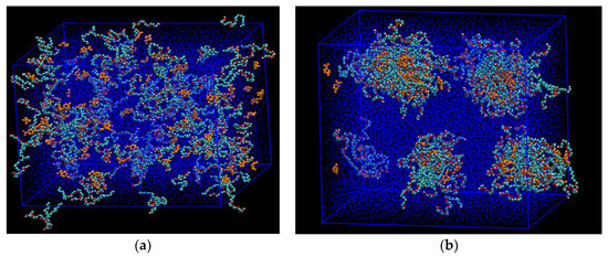
Figure 1.
A snapshot of the molecular dynamics (MD) simulations of the aqueous phase showing the development of the stabilized microemulsion droplets. (a) Starting condition, where C12E7 surfactant (cyan color) and the solubilized d-limonene solvent molecules (yellow color) were placed randomly inside the box with periodic boundary condition; (b) After 50 nanoseconds, the microemulsion droplets were established and stabilized at standard conditions. Water molecules are shown as blue dots.
Next, the data production runs were performed in the same ensemble to extract the fluid density and velocity. We performed nonequilibrium molecular dynamics simulations of steady-state fluid flow by the capillary walls. The steadiness was established using periodic boundary conditions at the inlet and outlet ends of the capillary and applying an external force field to water molecules, which introduced a constant rate of acceleration to the water phase. Typical magnitude of the acceleration in the simulations was 0.01 nanometers per nanosecond which was roughly equal to a pressure gradient of 0.65 psi per nanometer. Preliminary flow simulations using a 10 nanometer-long capillary showed that a minimum of 0.325 psi per nanometer was needed as a threshold pressure gradient for the fluid flow to begin. Once the steady state was reached, the velocity of the heptane molecules was recorded for another 2 nanoseconds, and then averaged over space and time. Note that the velocity at the microscopic scale obtained from the molecular simulations should not be directly compared with the macroscopic velocity since they are not at the same scale.
At a continuum scale, the Couette flow is frequently used to describe a shear-driven fluid motion. The traditional flow setup consists of two parallel plates at a distance h from each other. The upper plate translates in the x direction with a constant velocity u0, while the lower plate is kept stationary. As a result, the fluid between those two plates experiences a shear flow in the direction of the mobile plate. The boundary conditions are u(z = 0) = 0 and u(z = h) = u0. When a pressure gradient is imposed in the x direction parallel to the plates, the Navier–Stokes equation simplifies to
where dp/dx is the pressure gradient parallel to the plates, whereas the velocity gradient in the z direction perpendicular to the plates, μ, is the fluid viscosity. The solution to Equation (1) is given by the following:
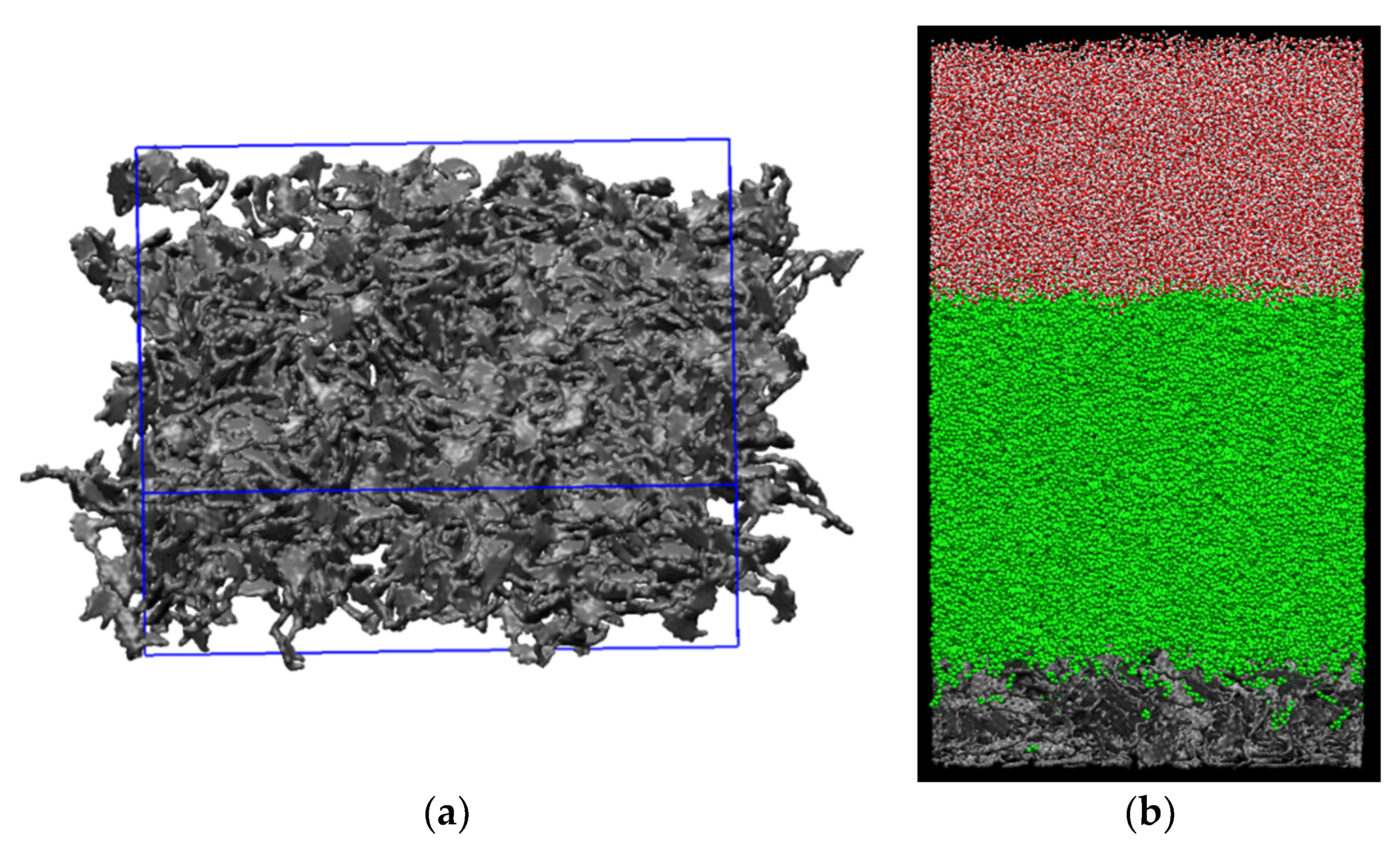
Since the pressure gradient during the steady-state flow is fixed, one would predict a linear velocity profile using Equation (2). Here, in our simulations the spacing between the two plates is taken by a layer oil and the upper plate translating in the x direction is replaced by the water phase. Thus, the shear-driven flow of oil phase is due to the nearby moving water phase. We achieved the translation of the water phase by subjecting the water molecules to uniform external force field (see Figure 2), which introduced a constant rate of acceleration to the water molecules. The consequence of this was a constant pressure gradient. Hence, one would expect a liner velocity profile across the oil film.
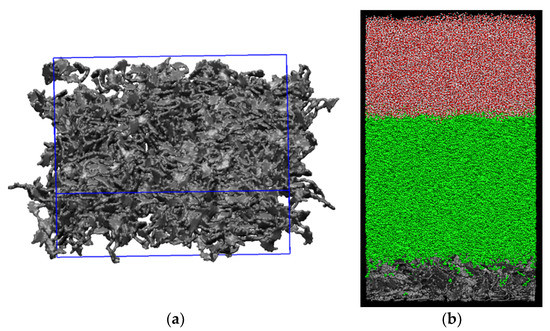
Figure 2.
A snapshot of (a) rough kerogen surface and (b) simulation box containing the solid kerogen surface at the bottom, oil phase in the middle, and water phase on top. The kerogen surface is 1 nm thick.
We considered the flow experiments for two different scenarios, i.e., with and without the presence of microemulsion. A single droplet, extracted from equilibrium simulations (Figure 1), was introduced into the aqueous phase. Accordingly, the introduced droplet went through the processes of droplet movement towards the interface, droplet adsorption, and the droplet breakup. By the end of the adsorption process following the breakup, the surfactant molecules stayed at the oil/water interface while the d-limonene molecules penetrated further into the oil film (see Figure 3). The mechanism of droplet adsorption also indicated that the solid–fluid interactions could be significantly modified and, in some cases, even amplified in the presence of the solvent. Having obtained the initial distribution of the microemulsion components in the organic capillary, next we considered producibility limits of the oil by the organic walls.

Figure 3.
Adsorption of a microemulsion droplet to the oil/water interface by the organic wall. The droplet arrives at the oil/water interface and breaks down; after that, solvent molecules penetrate further into the oil phase and approach to the pore wall. Reproduced with permission from [18].
3. Results and Discussion
3.1. Simulation of the Couette Flow by the Organic Wall
Using the external force field approach on the translational movement of the water molecules, we consider the molecular dynamics simulation of flow of water under steady-state conditions and gain insight into the influence of the chemicals on the mobilization of the oil film. We make careful angstrom-level observations by mapping the density and velocity profiles of the flowing phases perpendicular to the plate (wall) and by measuring the fractional flow of the phases. Note that an external force field is applied only to the water phase molecules located at the central portion of the capillary, and therefore the oil phase nearby the organic wall experiences the Couette flow. When water is flowing steadily along the x-axis, the momentum transferred to oil phase in the z direction leads to the shear flow of oil. The velocity profile can be extracted by averaging over thin slices along the z direction and over time under quasi-steady condition. This profile is across the half-length of the pore width, and hence represents the transport inside the capillary.
3.2. The Couette Flow of Pure Water and Oil
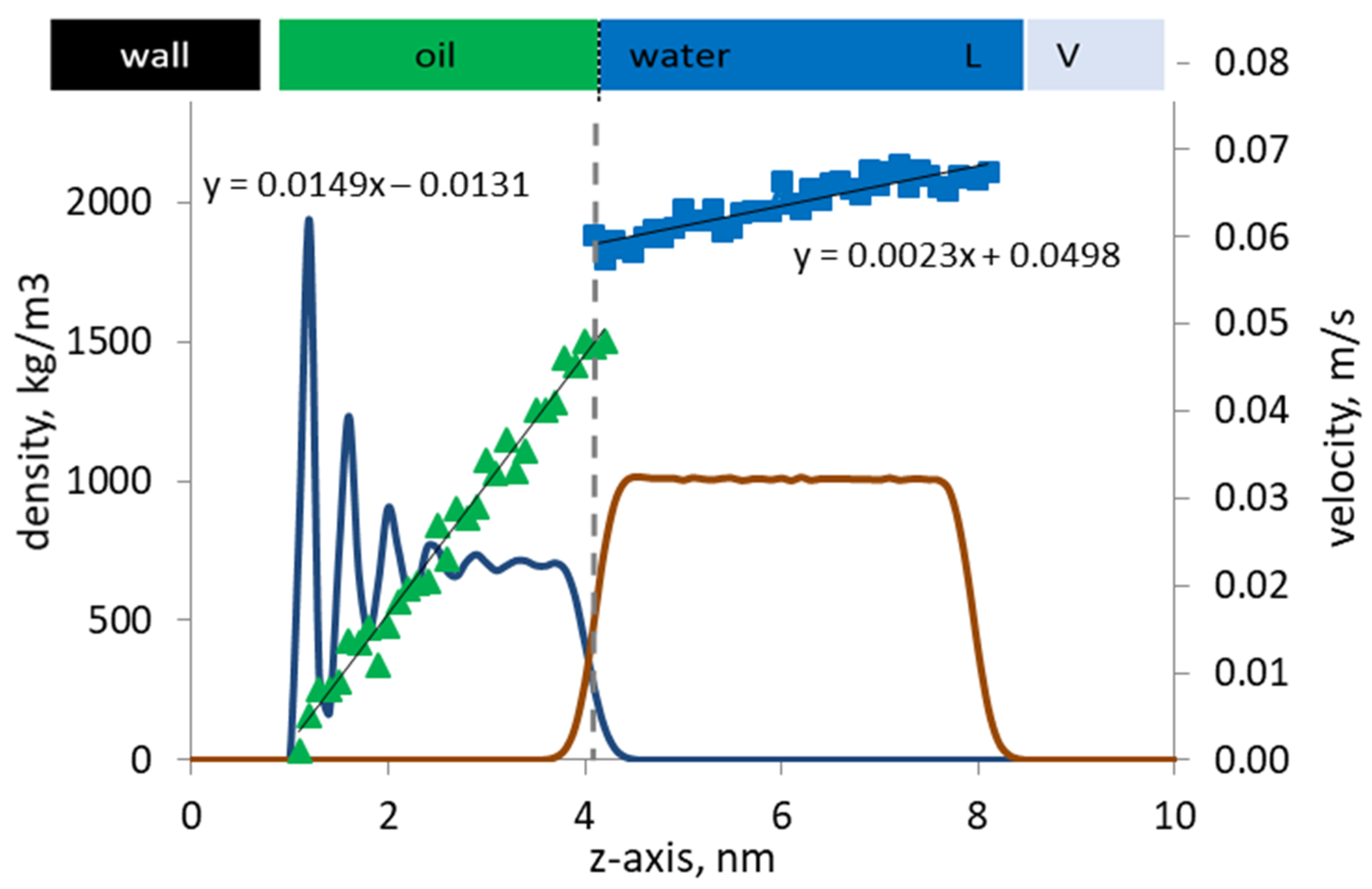
We first consider the Couette flow in the absence of dispersed microemulsion droplets. Figure 4 shows the phase density profiles near the organic wall. Due to adsorption, the density of oil near the wall is at its peak (1943 kg/m3). The oil phase close to the wall shows a layered structure due to strong affinity of the wall to the hydrocarbon molecules that make up the oil phase. The density profile shows a sharp drop further away from the wall. At about 3 nanometers distance from the wall, the density is stabilized and equal to the bulk density of heptane, 686 kg/m3. Further to the right, the water phase is located. Note that the density profile of water is relatively smooth. This is because the water molecules are further away from the organic walls, and thus they are the so-called “free” molecules. Due to periodicity in the boundary conditions, another “image” wall should exist on the right-hand side. But the effect of the image wall is dampened by including on the far right a thin layer of vapor, which is in equilibrium with the liquid water.
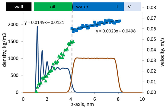
Figure 4.
Velocity profiles (discrete dots) of oil and pure water are shown along with the corresponding phase density profiles (continuous lines) by the kerogen capillary wall. The oil/water interface is marked with a vertical line.
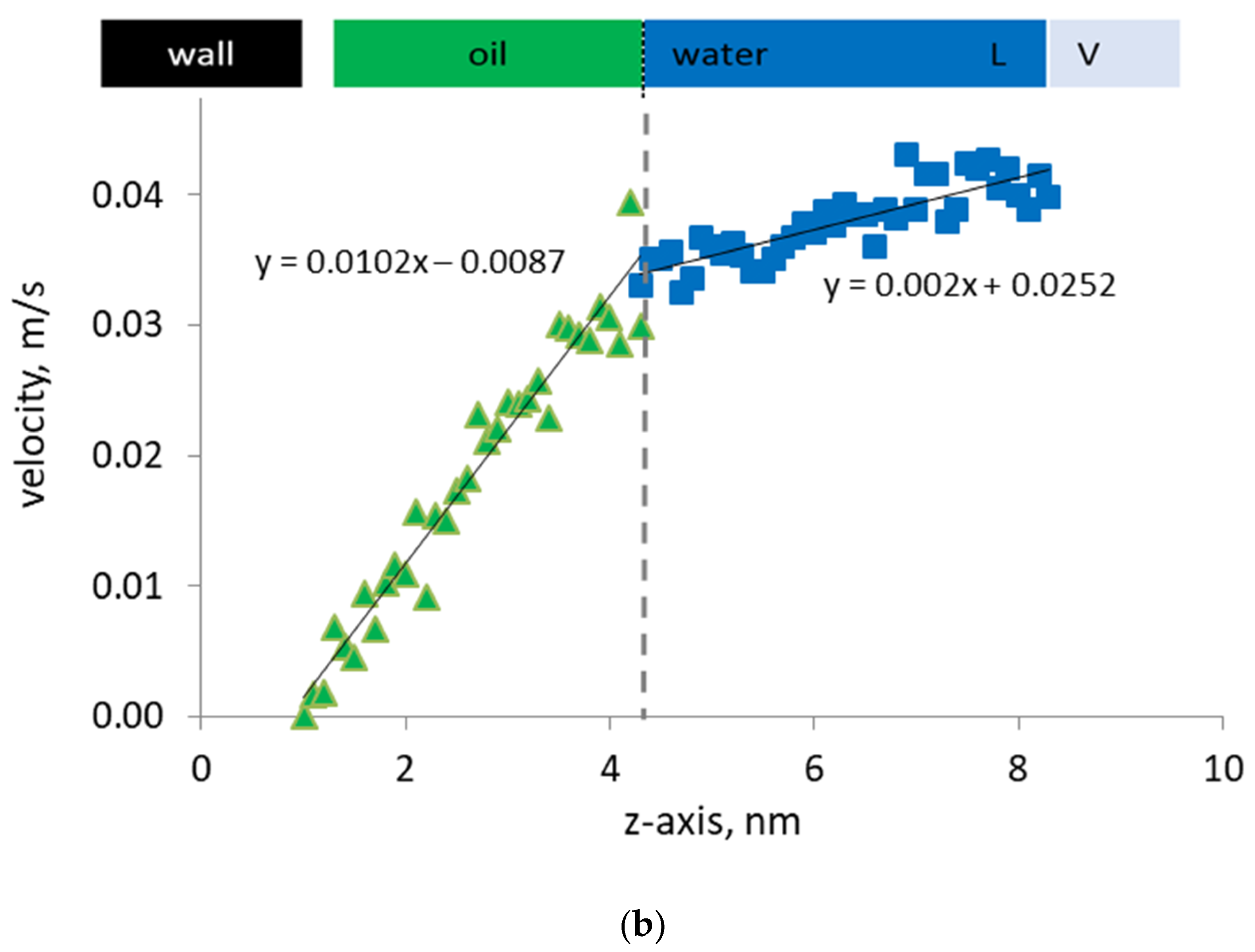
The velocity profiles of the oil and water phases are shown in Figure 4 along with their density profiles. The vapor phase density and velocity profiles are not shown for clarity in presentation. On the one hand, the computed velocity profiles are not too noisy, and the velocity profiles of the oil and water phases can be identified as parabolic trends. The Reynolds number of the flow is relatively low (~0.01), which ensures the existence of laminar flow regime, hence the parabolic velocity profiles observed. On the other hand, the velocity profile of the oil phase should be linear, as expected from the imposed Couette flow conditions. The coefficient of the quadratic term for the oil phase velocity is one order of magnitude smaller than that for the water phase, so that the quadratic term can be safely considered negligible, hence the computed profile is shown to be linear.
Importantly, a mismatch in the phase velocities exists at the oil/water interface, indicating the presence of slip. The flowing water molecules slip at the interface, and the slip velocity is defined as |uoil – uwater|/uoil at the interface. Note that the slip observed at the oil/water interface is independent of the Reynolds number but primarily controlled by the nature of the interfacial coupling between the oil and water phase at the molecular level. The adsorbed oil and solvent molecules can experience another slip by the pore wall, since the walls are modeled as smooth surfaces. However, in this work, we focus our analysis on the slip at the interface between water and oil.
3.3. Effect of Microemulsion Adsorption on the Couette Flow
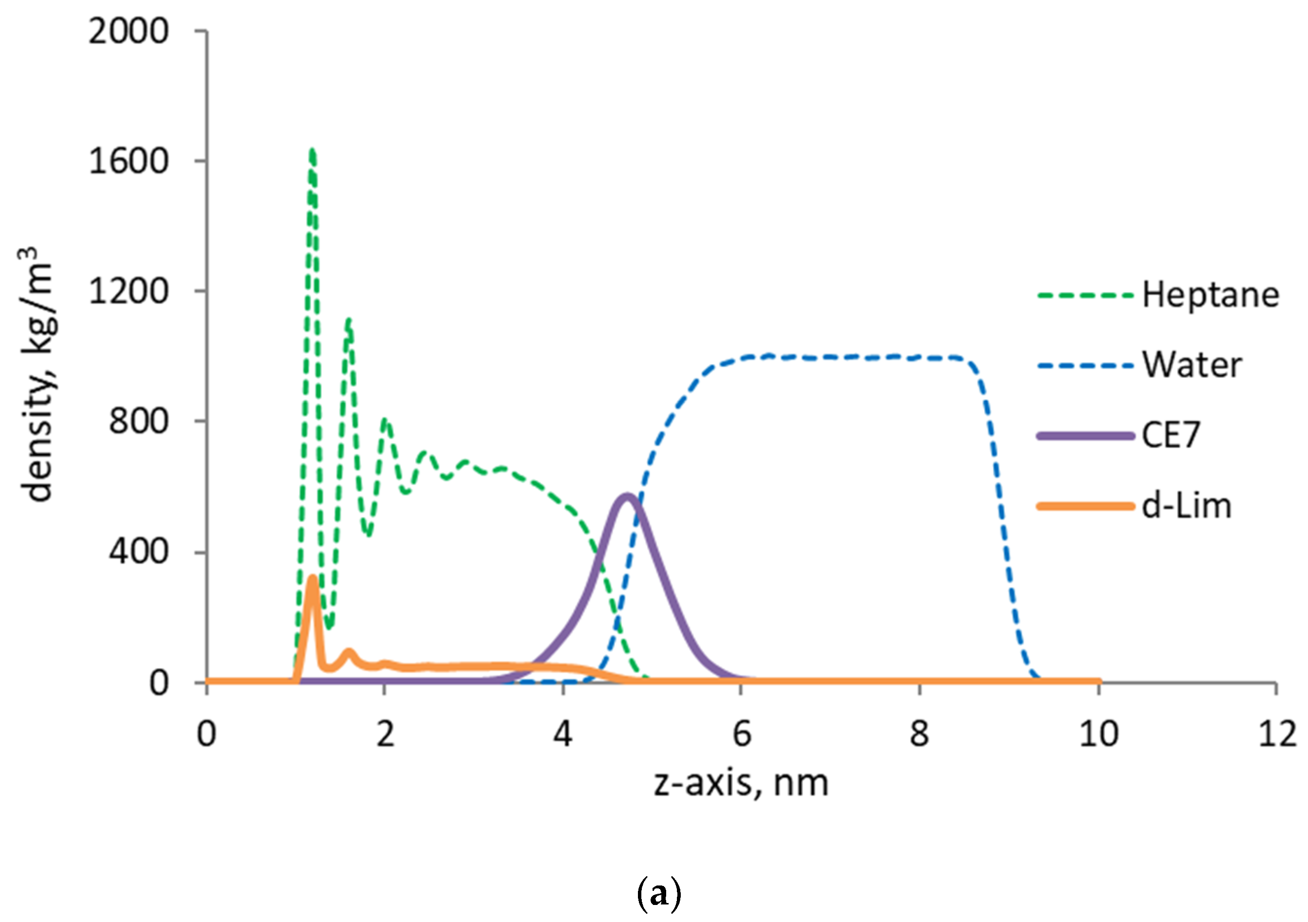
Now, we consider the flow in the presence of chemicals (surfactant and solvent) introduced to the system in the form of dispersed microemulsion droplets by the oil phase near the organic wall. The dissolution and redistribution of the dispersed molecules has already taken place in the oil and water phases. Let us analyze the simulation results of steady-state flow behavior by the organic capillary wall shown in Figure 5a. The water molecules are exposed to the same external force field and acceleration as in the previous case, in the absence of the chemicals. Hence, if the addition of chemicals has no effect in changing the multiphase flow, one would intuitively expect similar trends in densities and velocities, as previously observed. Note that the density profiles show that most of the introduced surfactant molecules ended up at the oil/water interface, while the solvent molecules were dissolved into the oil phase and adsorbed on the organic wall. The dissolution of the solvent molecules into the oil phase and adsorption led to a 16% reduction in the density of the adsorbed oil. In addition, the adsorbed solvent molecules displaced 14% of the adsorbed oil molecules and those oil molecules released into the free oil phase. If more solvent had been introduced, for example by delivering a larger number of solvent-swollen droplets, a larger number of solvent molecules would have been delivered to the oil phase and, a larger number of oil molecules by the walls would have been released. Indeed, there is an upper limit on how many additional solvent molecules can be introduced per surfactant molecule, because the addition of too many solvent molecules causes inversed micelle, which should be avoided in enhanced oil recovery. But the droplet concentration in the aqueous phase can be optimized.
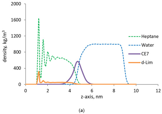
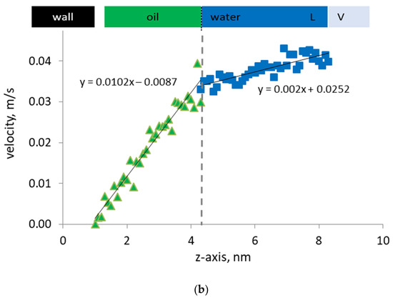
Figure 5.
(a) Density profiles of n-heptane (green), water (blue) in the presence of surfactant (purple), and d-limonene solvent (orange) by the organic capillary wall; (b) Velocity profiles of water and oil phase by the organic capillary wall under steady-state Couette flow.
In the presence of surfactant molecules at the oil/water interface, we observe that the slip velocity at the oil/water interface becomes a negligible quantity. As a consequence of this change in the local velocity field, the discontinuity previously observed in the velocity profile disappears and a very smooth and continuous velocity profile develops. Now, the velocities of the oil and water molecules at the interface are the same, which indicate that the surfactant molecules have effectively removed the discontinuity in the phase velocities. In essence, the surfactant becomes a link that transmits the momentum from the flowing water phase to the oil film by the wall. This also impacts the density profile across the interface by smearing the computed density and by smoothening the mass flux. Hence, not only the momentum but also the mass transfer in the pore develops more effectively. Consequently, less energy is needed at the same flow velocity and saturations to mobilize the oil phase and enhance the recovery.
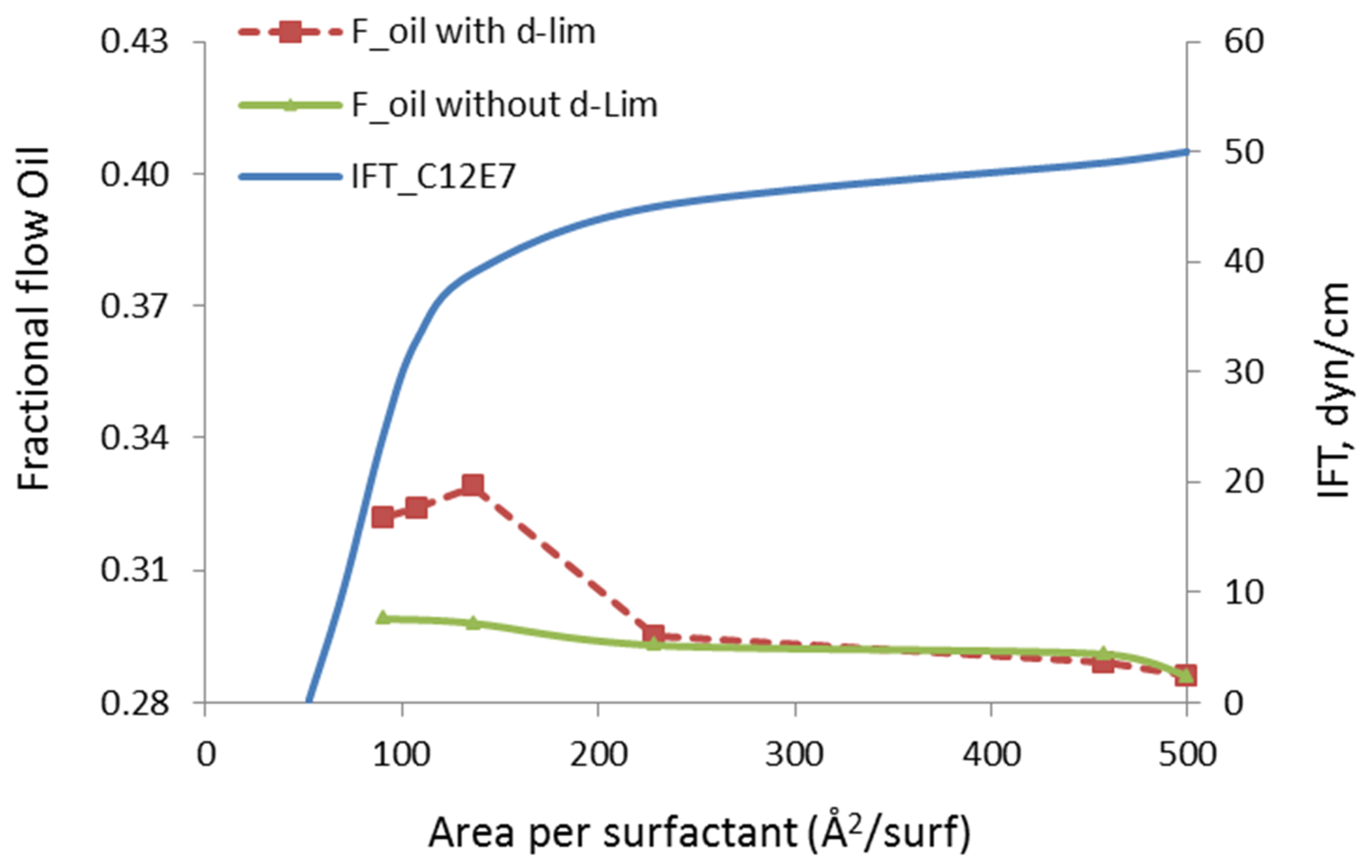
The fractional flow of oil, in our study, is defined as the mass flow of mobilized n-heptane divided by the total (n-heptane + water) mass flow in the channel. Note that the in situ oil and water saturations in the pore are fixed during the fractional flow calculations. The surfactant/solvent ratio is also fixed to the value that corresponds to the stable microemulsion droplet, as previously discussed in Figure 1, i.e., 42:54. The concentration of the surfactant molecules at the oil/water interface is varied. When the area of the interface is kept at 500 Å2/molecule or higher, the surfactant can be considered infinitely diluted and its impact on the oil recovery can be safely ignored. Hence, the fractional flow of oil at this infinite dilution limit corresponds to the case without microemulsion, i.e., including only the oil and water phases, shown in Figure 4. When the concentration of a surfactant at the interface is increased from the right to left side of Figure 6, the area per surfactant decreases. In other words, more surfactant was injected to reduce the IFT of the oil/water interface. The green curve in this chart is the fractional flow of oil phase when only surfactant was injected. Note that the surfactants at the oil/water interface eliminated the slip velocity and the fractional flow of the oil was increased by 4.5%. However, introducing the solvent molecules to the oil phase further increases the fractional flow, up to 15%. This indicates that the presence of the solvent introduces additional oil mobilization mechanism through the presence of the solvent. This could be due to the following two distinct effects: (i) reduced molecular interactions in between the in-place oil molecules and the organic wall, and (ii) modified rheological properties of the oil phase, for example, transform adsorbed oil into free oil.
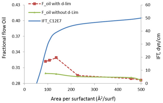
Figure 6.
Fractional flow of oil (Foil) with and without d-limonene solvent as a function of surfactant concentration at the interface.
One significant observation we make in Figure 6 is that the mobilization of oil and improvement in the its fractional flow develops at relatively high IFT values. The critical micellization concentration (CMC), in the presence of the surfactant develops at 46 Å2/surfactant and the value of IFT at that critical point is 0.2 mN/m. However, the observed increase in the fractional flow of oil occurs at much higher values, i.e., greater than 30 mN/m. This indicates that the enhancement in the oil recovery is not mainly due to reduction in IFT, but the solvent molecules’ penetration to the oil phase also makes a difference. Thus, we conclude that different mechanisms contribute to the oil mobilization and these mechanisms involve both surfactant and solvent molecules delivered by the microemulsion droplets.
3.4. Estimation of Hydrocarbon Recovery from 3D Kerogen Network
A large amount of solvent can be required to change the viscosity of the bulk oil phase for a conventional reservoir with a large pore volume. However, the requirement for enhanced oil recovery from source rocks can be much smaller. Delivered in the form of microemulsion, the solvent can be effective to mobilize highly viscous oil located in the vicinity of the organic solid surfaces. One of the previous studies indicated the viscosity of hydrocarbon mixture inside sub-10 nm pores can indeed be twenty or more times higher than the viscosity in the bulk phase. This viscous oil can be mobilized with the addition of a solvent [29,30]. This situation reflects challenges associated with the production from a tight pore space existing in the kerogen. If the kerogen pore space could be activated by applying suitable microemulsion chemistry, the production from kerogen could perhaps contribute significantly to the overall production of oil.
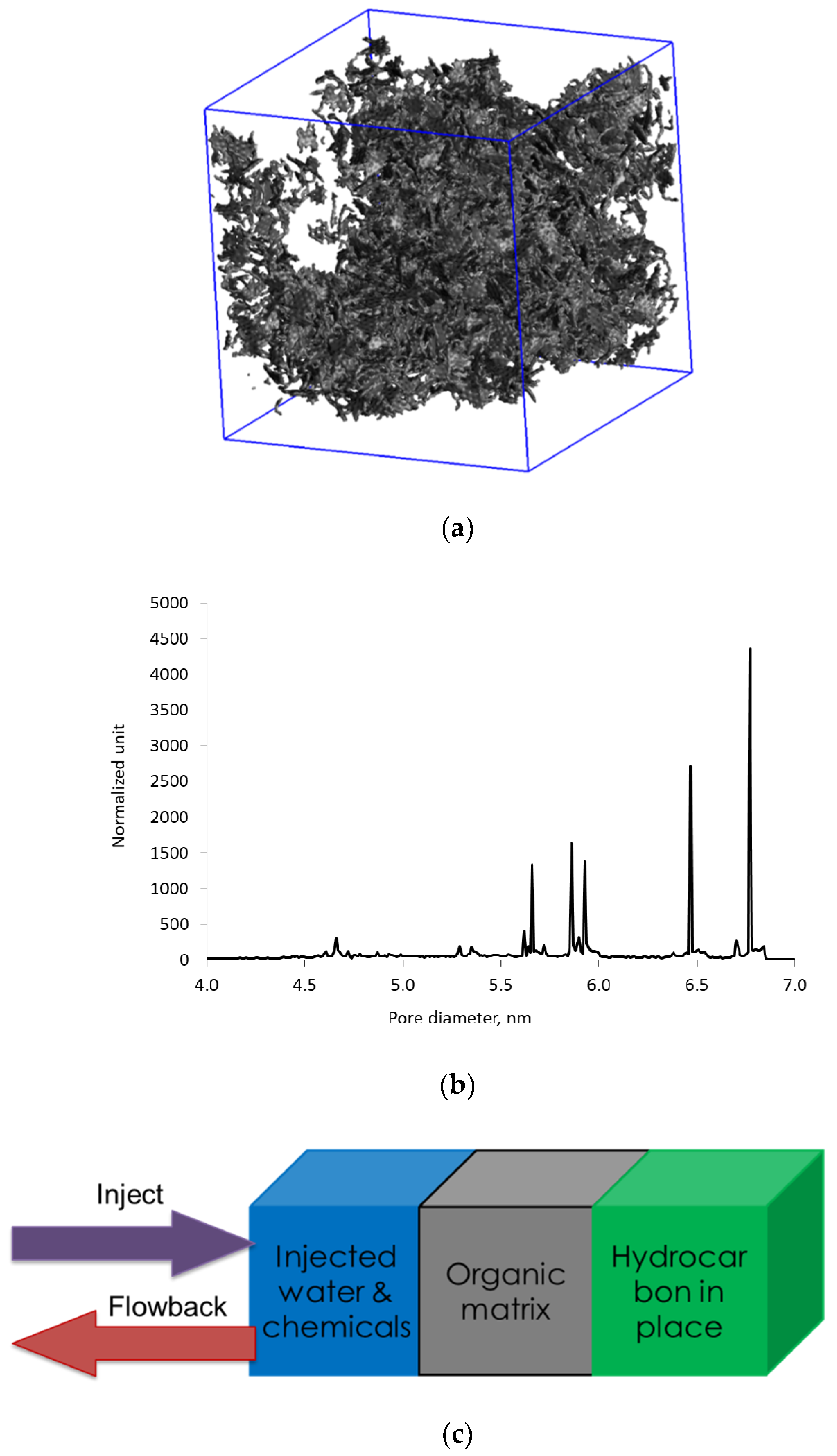
Modeling of hydraulic fracturing fluid injection into a kerogen structure and of subsequent flowback from kerogen is achieved via massive simulations, in which we combine several multiple functional blocks, as shown in Figure 7a. Each functional block is the outcome of a separate set of simulations. The blue block on the left-hand side is the aqueous phase containing 42,000 water molecules and a single microemulsion droplet similar to Figure 3. The size of the block is 12 nm, and the 6.5 nm microemulsion droplet consists of d-limonene solvent solubilized into the core of the nonionic C12E7 surfactant micelle. The middle gray block represents the 3D digital kerogen structure generated by reconstructing oil-saturated kerogen under the reservoir conditions. The green block represents the oil trapped in another section of kerogen of the same composition as kerogen in the gray block. Details of how to reconstruct the 3D kerogen network saturated with oil have been described in our previous work [31]. In summary, the oil molecules were randomly mixed with kerogen fragments inside a computational box. Then, high pressure and temperature conditions were applied and followed by slow quenching to mimic burial, fluid generation, and over-pressured reservoir conditions. The pore size of kerogen network ranges between 3.0 and 6.9 nm and the pores are saturated with a mixture of hydrocarbons. The green box is needed to maintain the hydrocarbon flow into the kerogen during the flowback. The green box is viewed as a reservoir replenishing oil in the kerogen after the oil in kerogen flows out to the fracture. Composition of the model oil in the green box and the kerogen are tabulated in Table 1.
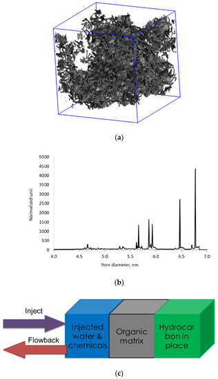
Figure 7.
(a) The three-dimensional (3D) atomistic model of kerogen saturated with oil at reservoir conditions corresponding to 150 bar and 80 °C; (b) Pore size distribution of the kerogen model indicating pore size range between 4 and 7 nm; (c) Diagram showing the setup of MD simulations to mimic the injection and flowback stage of oil production from a 3D kerogen network.

Table 1.
Composition of model oil.
During the injection stage, we applied an external force field to the blue block to simulate the injection pressure and to bring the aqueous phase in contact with the kerogen phase. Next, we performed the equilibrium simulation to allow the system to adjust to the new state. This equilibrium simulation represents the soaking (or shut-in) period during which the chemicals within the injected water are expected to achieve an equilibrium adsorption. To simulate the flowback process, we apply an additional pressure of 700 psi to the green block on the right in Figure 7a. This produces a pressure differential between the blue block and the green block. As a result of this pressure differential, the hydrocarbon molecules migrate towards the left side via the middle kerogen block. After carrying out the flowback simulation for 10 ns, we count the number of each type of hydrocarbon molecules that have moved out from the kerogen block. This allows us to calculate the recovery of each component of model oil, the combined recovery, and the ratios of C1–C4 and C8+ fractions, and the total recovery of oil. The results of numerical MD experiments are presented in terms of relative recovery with respect to initial oil in place. The term “recovery” used within the context of this study to quantify the number of hydrocarbon molecules of different kinds flowing out of kerogen nanopores, should not be confused with the conventional definition of the “recovery factor” including flow in the reservoir and production from a well. It is noteworthy that due to a very short simulation time of 10 ns, the calculated recovery is not expected to represent recoveries observed in the field. In addition, the variation of oil composition and many other factors, such as geomechanics, are not included in this work. In the MD simulations, the recovery factors for each fraction of the modal oils are estimated by counting the number of molecules of each type that can flow through the pore in the flowback experiments. For a more meaningful interpretation of the data, we perform binning of individual fractions into the “light ends”, consisting of C1–C4 fractions and “heavier ends” consisting of C8+ fractions. Then, the gas-to-oil ratio is estimated as the number of C1–C4 molecules recovered divided by the number of C8+ molecules recovered.
The geomechanical effects are not considered in this work, since we maintain the kerogen as a rigid body during the injection and the flowback. Hence, the results of the numerical experiments, in this work, give an expectation regarding only the chemical effects on the hydrocarbon recovery efficiency. The present study considers the following three principally different compositions of injected fluid: chemical-free pure water (Water), micellar solution of pure C12E7 nonionic surfactant (MIC), and a dispersion of microemulsion droplets (ME). To evaluate the effects of these different injection fluids, we only introduce changes into the blue block. It is worth emphasizing that the absolute number of surfactant molecules, i.e., 55 molecules, is the same for the C12E7 micelle and for the microemulsion droplet. The microemulsion droplet is composed of the 55 surfactant molecules and 86 d-limonene solvent molecules.
The results in Table 2 show small differences in the simulated oil production between stimulation with water and surfactant micellar (MIC) solution. The surfactant polar group adsorption occurs in both the surfactant micellar solution and the microemulsion. However, in the microemulsion (ME) scenario, the presence of solubilized solvent is expected to introduce an additional mechanism for oil mobilization, as presented in the section on the Couette flow and in Figure 5. The solvent helps to mobilize the heavy oil in the adsorbed phase by the kerogen pore wall. Hence, more C8+ fraction is recovered. In other words, the microemulsion’s impact on increased production is attributed more to its ability on C8+ mobilization than the changes in wettability as compare with injecting only the surfactant.

Table 2.
Recovery of hydrocarbon from 3D porous kerogen model having a pore size range between 4 and 7 nm. The results are the average of five different runs on the same kerogen sample.
4. Conclusions
A molecular dynamics simulation study is presented considering mobilization of the nanoconfined oil in the source rocks using aqueous phase solutions carrying microemulsions. The model solution represents the water injected during the fracturing operation. We showed that the residual oil trapped in the kerogen pores consist of free and adsorbed hydrocarbon molecules. These molecules can be mobilized up to a certain degree by applying viscous forces that are introduced by the injected solution. Following the dispersion of the droplets, the surfactants occupy the water/oil interfaces where they play the role of a link in between the oil and water phases. They smoothen the velocity and density profiles, eliminate the slip, and increase the effectiveness of the momentum transfer from the flowing water phase to the oil. The dispersed solvent molecules penetrate the oil phase and adsorb by the organic pore walls. In this way, they displace and free a portion of the adsorbed hydrocarbon molecules. These molecular scale modifications lead to mobilization of the oil. We quantify the amount by monitoring the fractional flow of oil in the presence of dispersed microemulsion molecules.
The use of microemulsion indicates effective mobilization of heavier oil fractions inside the kerogen network having pores with sizes in the range of 4 to 7 nm. Specifically, the use of microemulsion yielded an increase of oil production as compared with the case of injecting only surfactant or water. The simulation data shows these results can be attributed to the mobilization of heavier (C8+) oil fractions.
Author Contributions
Methodology, K.B.; Project administration, J.A.S.; Supervision, I.Y.A.; Visualization, K.B.; Writing—original draft, K.B.; Writing—review and editing, I.Y.A. and J.A.S. All authors have read and agreed to the published version of the manuscript.
Funding
This research was funded by Flotek Chemistry LLC. The computational work presented was performed using Texas A&M University supercomputer facility.
Conflicts of Interest
The authors declare no conflict of interest.
References
- Potter, P.E.; Maynard, J.B.; Depetris, P.E. Mud and Mudstones: Introduction and Overview; Springer: New York, NY, USA, 2004. [Google Scholar]
- Ambrose, R.J.; Hartman, R.C.; Diaz-Campos, M.; Akkutlu, I.Y.; Sondergeld, C.H. Shale Gas-in-Place Calculations Part I: New Pore-Scale Considerations. SPE J. 2012, 17, 219–229. [Google Scholar] [CrossRef]
- Loucks, R.G.; Reed, R.M.; Ruppel, S.C.; Hammes, U. Spectrum of Pore Types and Networks in Mudrocks and a descriptive classification for matrix-related Mudrock Pores. AAPG Bull. 2012, 96, 1071–1098. [Google Scholar] [CrossRef]
- Palciauskas, V.V.; Domenico, P.A. Microfracture Development in Compacting Sediments: Relation to Hydrocarbon-Maturation Kinetics. AAPG Bull. 1980, 64, 927–937. [Google Scholar]
- Orendt, A.M.; Pimienta, I.S.O.; Badu, S.R.; Solum, M.S.; Pugmire, R.J.; Facelli, J.C.; Locke, D.R.; Chapman, K.W.; Chupas, P.J.; Winans, R.E. Three-Dimensional Structure of the Siskin Green River Oil Shale Kerogen Model: A Comparison between Calculated and Observed Properties. Energy Fuels 2013, 27, 702–710. [Google Scholar] [CrossRef]
- Bousige, C.; Ghimbeu, C.M.; Vix-Guterl, C.; Pomerantz, A.E.; Suleimenova, A.; Vaughan, G.; Garbarino, G.; Feygenson, M.; Wildgruber, C.; Ulm, F.-J.; et al. Realistic molecular model of kerogen’s nanostructure. Nat. Mater 2016. advance online publication. [Google Scholar] [CrossRef]
- Ungerer, P.; Collell, J.; Yiannourakou, M. Molecular Modeling of the Volumetric and Thermodynamic Properties of Kerogen: Influence of Organic Type and Maturity. Energy Fuels 2015, 29, 91–105. [Google Scholar] [CrossRef]
- Kim, S.; Kramer, R.W.; Hatcher, P.G. Graphical Method for Analysis of Ultrahigh-Resolution Broadband Mass Spectra of Natural Organic Matter, the Van Krevelen Diagram. Anal. Chem. 2003, 75, 5336–5344. [Google Scholar] [CrossRef] [PubMed]
- Chilingarian, G.V.; Yen, T.F. Oil Shale; Elsevier: Amsterdam, The Netherlands; Oxford, UK; New York, NY, USA, 1976; Volume 1, p. 292. [Google Scholar]
- Adesida, A.G.; Akkutlu, I.; Resasco, D.E.; Rai, C.S. Characterization of Barnett Shale Kerogen Pore Size Distribution Using DFT Analysis and Grand Canonical Monte Carlo Simulations; Society of Petroleum Engineers: Hague, The Netherlands, 2011; p. SPE-147397-MS. [Google Scholar]
- Passey, Q.R.; Bohacs, K.; Esch, W.L.; Klimentidis, R.; Sinha, S. From Oil-Prone Source Rock to Gas-Producing Shale Reservoir - Geologic and Petrophysical Characterization of Unconventional Shale Gas Reservoirs. In International Oil and Gas Conference and Exhibition; Society of Petroleum Engineers: Hague, The Netherlands, 2012. [Google Scholar]
- Josh, M.; Esteban, L.; Delle Piane, C.; Sarout, J.; Dewhurst, D.N.; Clennell, M.B. Laboratory characterisation of shale properties. J. Pet. Sci. Eng. 2012, 88–89, 107–124. [Google Scholar] [CrossRef]
- Kang, S.M.; Fathi, E.; Ambrose, R.J.; Akkutlu, I.Y.; Sigal, R.F. Carbon Dioxide Storage Capacity of Organic-Rich Shales. SPE J. 2011, 16, 842–855. [Google Scholar] [CrossRef]
- Santos, J.M.; Akkutlu, I.Y. Laboratory Measurement of Sorption Isotherm under Confining Stress with Pore-Volume Effects. SPE J. 2013, 18, 924–931. [Google Scholar] [CrossRef]
- Zelenev, A.S.; Ellena, L. Microemulsion Technology for Improved Fluid Recovery and Enhanced Core Permeability to Gas; Society of Petroleum Engineers: Hague, The Netherlands, 2009. [Google Scholar]
- Zelenev, A.S.; Champagne, L.M.; Hamilton, M. Investigation of interactions of diluted microemulsions with shale rock and sand by adsorption and wettability measurements. Colloids Surf. A Physicochem. Eng. Asp. 2011, 391, 201–207. [Google Scholar] [CrossRef]
- Champagne, L.M.; Zelenev, A.S.; Penny, G.S.; Travis, K. Critical Assessment of Microemulsion Technology for Enhancing Fluid Recovery from Tight Gas Formations and Propped Fractures; Society of Petroleum Engineers: Hague, The Netherlands, 2011. [Google Scholar]
- Bui, K.; Akkutlu, I.Y.; Zelenev, A.; Saboowala, H.; Gillis, J.R.; Silas, J.A. Insights Into Mobilization of Shale Oil by Use of Microemulsion. SPE J. 2016, 21, 613–620. [Google Scholar] [CrossRef]
- Somasundaran, P.; Zhang, L. Adsorption of surfactants on minerals for wettability control in improved oil recovery processes. J. Pet. Sci. Eng. 2006, 52, 198–212. [Google Scholar] [CrossRef]
- Curbelo, F.D.S.; Santanna, V.C.; Neto, E.L.B.; Dutra, T.V., Jr.; Dantas, T.N.C.; Neto, A.A.D.; Garnica, A.I.C. Adsorption of nonionic surfactants in sandstones. Colloids Surf. A Physicochem. Eng. Asp. 2007, 293, 1–4. [Google Scholar] [CrossRef]
- Steele, W.A. The interaction of rare gas atoms with graphitized carbon black. J. Physical Chem. 1978, 82, 817–821. [Google Scholar] [CrossRef]
- Van Der Spoel, D.; Lindahl, E.; Hess, B.; Groenhof, G.; Mark, A.E.; Berendsen, H.J.C. GROMACS: Fast, flexible, and free. J. Comput. Chem. 2005, 26, 1701–1718. [Google Scholar] [CrossRef]
- Hess, B.; Kutzner, C.; van der Spoel, D.; Lindahl, E. GROMACS 4: Algorithms for Highly Efficient, Load-Balanced, and Scalable Molecular Simulation. J. Chem. Theory Comput. 2008, 4, 435–447. [Google Scholar] [CrossRef]
- Humphrey, W.; Dalke, A.; Schulten, K. VMD: Visual molecular dynamics. J. Mol. Graph. 1996, 14, 33–38. [Google Scholar] [CrossRef]
- Jorgensen, W.L.; Tirado-Rives, J. The OPLS [optimized potentials for liquid simulations] potential functions for proteins, energy minimizations for crystals of cyclic peptides and crambin. J. Am. Chem. Soc. 1988, 110, 1657–1666. [Google Scholar] [CrossRef]
- Jorgensen, W.L.; Maxwell, D.S.; Tirado-Rives, J. Development and Testing of the OPLS All-Atom Force Field on Conformational Energetics and Properties of Organic Liquids. J. Am. Chem. Soc. 1996, 118, 11225–11236. [Google Scholar] [CrossRef]
- Berendsen, H.J.C.; Grigera, J.R.; Straatsma, T.P. The missing term in effective pair potentials. J. Phys. Chem. 1987, 91, 6269–6271. [Google Scholar] [CrossRef]
- Tummala, N.R.; Shi, L.; Striolo, A. Molecular dynamics simulations of surfactants at the silica–water interface: Anionic vs nonionic headgroups. J. Colloid Interface Sci. 2011, 362, 135–143. [Google Scholar] [CrossRef] [PubMed]
- Bui, K.; Akkutlu, I.Y. Hydrocarbons Recovery from Model Kerogen Nanopores. SPE J. 2017, 22, 854–862. [Google Scholar] [CrossRef]
- Hernandez, H.W.; Ehlert, W.; Trabelsi, S. Removal of Crude Oil Residue from Solid Surfaces using Microemulsions. Energy Fuels 2019, 237, 398–404. [Google Scholar] [CrossRef]
- Bui, K.; Akkutlu, I.Y.; Zelenev, A.; Hill, W.A. Kerogen Maturation Effects on Pore Morphology and Enhanced Shale Oil Recovery. In SPE Europec Featured at 80th EAGE Conference and Exhibition; Society of Petroleum Engineers: Copenhagen, Denmark, 2018; p. 13. [Google Scholar]
© 2020 by the authors. Licensee MDPI, Basel, Switzerland. This article is an open access article distributed under the terms and conditions of the Creative Commons Attribution (CC BY) license (http://creativecommons.org/licenses/by/4.0/).

