Article

Numerical Study of a Liquid Metal Oscillating inside a Pore in the Presence of Lorentz and Capillary Forces

by
Maria Vlachomitrou
* and
Nikos Pelekasis
Department of Mechanical Engineering, University of Thessaly, Leoforos Athinon, Pedion Areos, 38334 Volos, Greece
*
Author to whom correspondence should be addressed.
Fluids 2020, 5(1), 12; https://doi.org/10.3390/fluids5010012
Submission received: 25 November 2019 / Revised: 23 December 2019 / Accepted: 3 January 2020 / Published: 8 January 2020
(This article belongs to the Special Issue Coupled Flow and Heat or Mass Transport)

Abstract

:
In order to ensure stable power exhaust and to protect the walls of fusion reactors, liquid metals that are fed to the wall surface through a capillary porous system (CPS) are considered as alternative plasma-facing components (PFCs). However, operational issues like drop ejection and plasma contamination may arise. In this study, the unsteady flow of a liquid metal inside a single pore of the CPS in the presence of Lorentz forces is investigated. A numerical solution is performed via the finite element methodology coupled with elliptic mesh generation. A critical magnetic number is found (Bondm = 4.5) below which the flow after a few oscillations reaches a steady state with mild rotational patterns. Above this threshold, the interface exhibits saturated oscillations. As the Lorentz force is further increased, Bondm > 5.8, a Rayleigh–Taylor instability develops as the interface is accelerated under the influence of the increased magnetic pressure and a finite time singularity is captured. It is conjectured that eventually, drop ejection will take place that will disrupt cohesion of the interface and contaminate the surrounding medium. Finally, the dynamic response of different operating fluids is investigated, e.g., gallium, and the stabilizing effect of increased electrical conductivity and surface tension is demonstrated.

1. Introduction

It is widely known that the global oil and gas resources are diminishing, and in order to avoid an energy crisis in the future, alternative sources of energy must be explored and implemented. Thermonuclear fusion is perhaps the most promising one since it offers a profuse energy supply without seriously affecting the environment [1,2]. It is based on the fusion reaction between deuterium and tritium that produces a helium nucleus and a neutron, releasing a high amount of energy. This reaction does not occur spontaneously, but instead a temperature of 150 million degrees Celsius is needed inside the reactor. In these conditions, the gases are ionized and in a plasma state. Moreover, a magnetic field is usually needed to control the confinement of the plasma in the reactor. For these reasons, the design of a fusion reactor is a challenging task and several issues must be addressed before this idea becomes widely applicable. The Eurofusion Plant Physics and Technology Work Program aims at putting in operation a demonstration fusion power reactor (DEMO) by 2050.
One of the critical issues regarding the reactor design has to do with the wall as it experiences very high heat loads. The Eurofusion ITER Physics Program investigates solutions to manage the plasma’s heat exhaust, especially for the divertor, which is the area of the reactor wall that receives the highest heat and particle fluxes. Divertor walls made of tungsten can withstand heat loads up to 20 MW/m2; otherwise, operational problems, such as erosion, thermal fatigue, and plasma contamination, may occur. However, estimates based on available divertor performance data suggest that the heat load could be as large as 50 to 100 MW/m2 and even higher for the DEMO reactor [3]. In order to avoid the above operational problems, liquid metals are considered as alternative plasma-facing components (PFCs) [3,4,5]. The most common metal used for this purpose is lithium (Li) as it showed a beneficial impact on plasma operation. Furthermore, due to its low melting point, a vapor cloud is formed between the plasma and the wall, which acts like a shield and protects the PFC [6]. Besides Li, tin (Sn), gallium (Ga), and aluminum (Al) have also been considered [7]. There is convincing evidence in the literature that the most efficient way to transfer the liquid metal to the wall reactor and thus protect its surface is through a capillary porous system (CPS) [3,8,9]. When the coverage of the wall reactor by the liquid metal film is significantly reduced due to evaporation, the CPS can replenish the liquid metal coating through capillary pressure without the need to apply additional external pressure. Such a system has the advantage that it is self-regulating because it reacts to liquid metal depletion on the interface. It has been suggested that with the proper use of such a system, heat loads of hundreds of MW/m2 can be handled [10].
A serious issue that may arise when a liquid metal is used as a PFC pertains to the possibility of drop ejection and thus contamination of the plasma taking place. In the literature, there are many experimental studies involving liquid PFCs, especially liquid lithium, that try to identify and improve the operational stability limits for temperature and induced thermal loads. Additionally, an effort is made to examine the possible contamination of the liquid film with impurities from the plasma, since this may reduce the effectiveness of the film as a coolant and cause severe operational problems as well. For example, Whyte et al. [11] performed several experiments on the DIII-D tokamak and reported unstable behavior of liquid lithium in the form of droplet ejection. The same behavior was observed by Zuo et al. [12], who monitored lithium droplets with radii 0.5 to 5 mm in experiments in the HT-7 tokamak. On the other hand, experiments performed by Evtkhin et al. [13] in the T11-M device and by Apicella et al. [14] in the Frascati Tokamak Upgrade (FTU) device did not capture ejection, but instead, the liquid film showed stability for the operational parameters used. A similar behavior was reported by Jaworski et al. [15] for the liquid lithium tokamak divertor in the National Spherical Torus Experiment (NSTX). Nevertheless, in the same study, they argued that in such flow arrangements, there is a strong possibility for drop ejection due to Kelvin–Helmholtz or Rayleigh–Taylor instabilities. For the latter case, they conjectured that there is a critical pore size below which the liquid metal film becomes unstable.
Contrary to experimental studies, the CPS has not been the subject of extensive modelling activity partly due to the complex flow arrangement of the limiter containing the liquid metal. Available studies focus on the importance of the capillary forces to supply a mass flow rate of lithium through the CPS system via a balance between the pressure drop and resistance to flow [10,16]. Other studies have considered the macroscopic scale and analyzed the thermoelectric magnetohydrodynamic (TEMHD) forces caused by temperature gradients in the liquid–container system [17] or focused on analytical solutions for simplified flow and calculated the surface velocity due to thermocapillary effects in conjunction with magnetohydrodynamic drag [18].
In this work, in order to provide an in-depth understanding of the involved phenomena, we focused inside a single pore of the CPS and we numerically investigated the dynamic behavior of the liquid metal. An emphasis was placed on understanding the interplay between the different forces that act towards pushing the liquid metal out of the pore or resist its motion and in determining the conditions and the limits for stable power exhaust. We followed the approach of Benos et al. [19,20], who studied the static arrangement of the liquid metal, both when it is limited inside a single pore using a fixed contact point approach and while it rests on the CPS top surface. More specifically, in the latter study, the effects of the reservoir overpressure, electric stresses, and Lorentz force (jxB) effects were investigated on the static film arrangement. In particular, by taking into consideration the interaction potential [21] between the solid substrate and the liquid metal in order to obtain a quantitative measure of the wetting properties of the latter, it was seen that, depending on the material and process properties, the static arrangement conforms with the fixed contact point or the fixed contact angle assumption [20]. In our case, we employed the above obtained solution as an initial condition for the static configuration of the liquid metal inside the pore and assumed a fixed contact point arrangement, with the liquid metal remaining constantly in contact with the pore mouth. This is viewed as a starting point for the analysis of the dynamic behavior of the porous structure in response to an external electric current entering the CPS during operation of the reactor in the presence of a strong external magnetic field. The main goal of the study was to identify conditions for the loss of stability and drop ejection to take place in parts or the whole of the liquid–metal interface, as the intensity of the electric current increases.

2. Materials and Methods

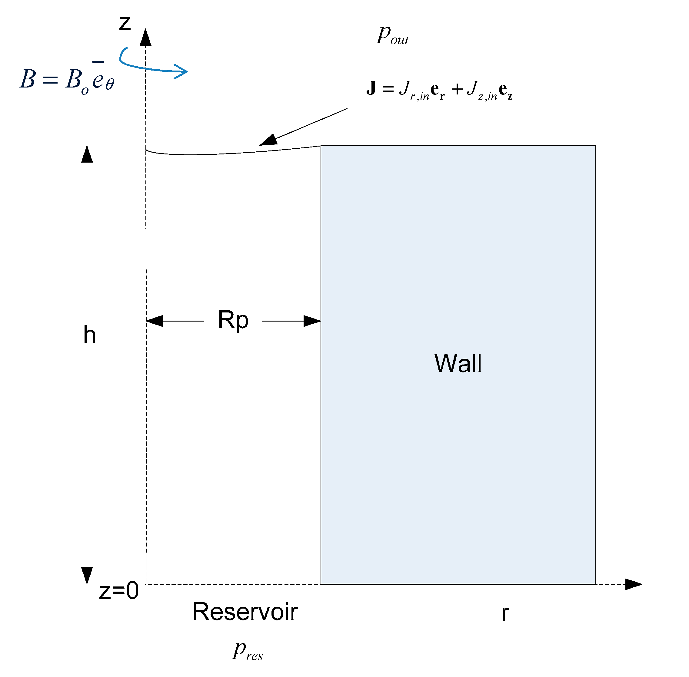
2.1. Problem Formulation

The unsteady flow arrangement of a liquid metal inside a single pore of the CPS in the presence of a magnetic field was investigated in order to dynamically study the behavior of the liquid in the presence of Lorentz and capillary forces. The pore was considered as a thin rigid cylinder that has a radius, R p , which is much smaller compared to its height, h . Initially, an external constant magnetic field was applied on the interface, directed towards the azimuthal direction B = B o e θ , while the liquid rests at static equilibrium. In Figure 1, a schematic representation of the flow under consideration is provided.
In order to obtain the governing equations, we only allowed for axisymmetric variations of the flow arrangement. Furthermore, the liquid metal of a density, ρ, and viscosity, μ, was considered as incompressible and thus the flow is governed by the continuity equation and momentum balance via the Navier–Stokes equations:
u = 0 ,
u t + ( u ) u = 1 ρ p + g + 1 ρ F L + μ ρ · τ = , τ = = u + u T 2 ,
where τ = is the deviatoric stress tensor in the fluid and F L is the Lorentz force:
F L = J x B = ( x H ) x Β o = H z B o e z B o r ( r H ) r e r = ( H B o ) B o H r e r .
In the above, J = J r e r + J z e z denotes the electric current in the pore region while H = H e θ = ( B i / μ m ) e θ is associated with the magnetic induction and also serves as the stream function of the electric current via Ampere’s law; μm denotes the magnetic permeability of the liquid metal. The quantity H B o represents the magnetic pressure, whereas B o H r corresponds to the rotational part of the Lorentz force. By introducing a transformed pressure that includes the gravity and the magnetic pressure, the Navier–Stokes equations become:
u t + ( u ) u = 1 ρ p + μ ρ τ = B 0 H ρ r e r
p = p + H B 0 + ρ g z .
In the above, primed quantities have dimensions, τ′ denotes the deviatoric stress tensor that is associated with viscous stresses, and p″ is the dimensional transformed pressure. The radius of the pore, R p , is taken as the characteristic length scale of the problem, whereas the quantity σ / R p is used as the pressure scale, with σ denoting the surface tension. By requiring that pressure forces be of the same order of magnitude as convection forces, the characteristic velocity, u ¯ , is set to ( σ / ρ R p ) 1 / 2 . Finally, the stream function of the electric current is non-dimensionalized with the quantity J r , i n R p , with J r , i n being a measure of the intensity of the electric current that enters the pore at its interface with the surrounding medium. This represents the electric current that may be generated in the bulk of the plasma reactor, as a result of an instability, that will disrupt normal operation of the divertor region, possibly leading to loss of cohesion of the liquid metal film that protects it, followed by drop ejection. In this context, the dimensionless governing equations of the flow are:
u = 0 ,
u t + ( u ) u = p + 1 R e τ = B o n d m H r e r ,
where p is the dimensionless transformed pressure, R e = ( ρ R p σ ) 1 / 2 / μ is the Reynolds number that compares the surface with the viscous forces, and B o n d m = ( J r , i n R p 2 B o ) / σ is the magnetic Bond number, which compares the magnetic with the surface forces.
By introducing the transformed pressure, the force balance equation on the plasma–liquid metal interface reads in a dimensionless form:
n ( p B o n d m H B o n d z int p o u t ) I = 1 Re τ = n + 2 H c n = 0
p ^ = p + B o n d m H + B o n d z int ,
where n denotes the unit normal vector pointing outwards from the liquid metal, I = is the unit tensor, zint is the z-coordinate of the interface, Hc is the mean curvature of the interface, and B o n d = ( ρ g R p 2 ) / σ is the gravitational Bond number that compares the gravity with the surface forces. Clearly, this is a first attempt towards simulating plasma wall interaction, where only the plasma pressure and electric current from the bulk of the reactor are taken into consideration.
On the interface, the mass balance assumes the dimensionless form:
u l , n = u s , n = n ( r int t e r + z int t e z ) , n = z int , ξ e r + r int , ξ e z z int , ξ 2 + r int , ξ 2 ,
with u l and u s , n denoting the normal velocity of the liquid at the interface and of the interface, respectively, n the unit normal vector at the interface pointing outwards with respect to the liquid metal, and r s = r int ( ξ ) e r + z int ( ξ ) e z is the Lagrangian representation of the interface. Furthermore, we adopted a fixed contact point approach [19,20] for the shape of the interface as it approaches the pore–substrate interface at the top, and the boundary conditions corresponding to the liquid metal velocity and the location of the interface at the pore wall are:
u r ( r = 1 , z ( r = 1 ) ; t ) = u z ( r = 1 , z ( r = 1 ) ; t ) = 0 , z int ( r = 1 ; t ) = h / R p .
At the pore entrance located at its interface with the reservoir, we assumed fully developed flow conditions, with τzz and τrz denoting the normal and tangential components of the viscous stress vector and pres is the fixed reservoir pressure:
τ z z ( z = 0 ) = τ r z ( z = 0 ) = 0 , p ^ ( z = 0 , r ; t ) = p r e s + B o n d m H ( z = 0 ; t ) .
The pressure has a prescribed value at the pore entrance level, z = 0, that was set to zero without any loss of generality, leaving pout as the sole parameter that controls the surrounding/reservoir overpressure. Nevertheless, the transformed pressure is not zero at the pore entrance as it is affected by the magnitude of the magnetic pressure. Finally, symmetry conditions are imposed at the pore axis:
u r ( r = 0 , z ) = u z r ( r = 0 , z ) = z int r ( r = 0 , z ) = 0 .
Upon enforcing continuity of the electric charge by combining Ampere‘s law with Ohm‘s law, the following dimensionless equation is obtained for the stream function, H:
2 H H r 2 = c 1 r u r , c = B o λ J r , i n ( σ ρ R p ) 1 / 2 ,
where λ is the electrical conductivity of the liquid metal [20]. It should be stressed that in the above relation, the magnetic Reynolds, Re m λ μ m R p u ¯   , was treated as a small number, signifying the fact that the magnetic induction is much smaller than the external magnetic field [22]. Parameter c is a measure of the relative importance of the induced electric current due to the electric conductivity of the liquid metal and the external electric current. The electric current anywhere inside the pore is calculated via its stream function:
J = x H J r = H z , J z = 1 r ( r H ) r .
If we assume a known dimensionless distribution of the electric current components, J r , i n , J z , i n , on the interface with the plasma, the following boundary conditions apply at the pore entrance and exit where it meets the reservoir and substrate, respectively:
z z int : J r , i n = H z | int , J z , i n = 1 r ( r H ) r | int ,
z = 0 : H = r J t o t 2 ,
r = 0 : H = 0 ,   r = 1 : J r = 0 H = r J t o t 2 ,
J t o t = 2 0 1 ( J r , i n z int ξ + J z , i n r int ξ ) r d ξ ,
where Jtot denotes the dimensionless total electric current entering the pore at its interface with the surrounding medium, calculated via its known radial and axial distribution at the pore interface coupled with the conservation of the electric current. This value is also used to fix the transformed pressure at the interface with the reservoir. The rest of the boundary conditions in Equations (17) and (18) reflect the assumption of electrically insulated pore walls, symmetry of the electric current at the axis of symmetry r = 0, and fully developed electric current distribution at the pore entrance. Finally, it should be pointed out that the azimuthal component of the magnetic field employed in the present study does not satisfy the condition of irrotationality, and consequently, care should be taken to avoid the introduction of spurious electric currents via application of Ampere’s law. However, this issue is circumvented, for the low magnetic Reynolds number situation examined in the present study, by the introduction of the stream function, H [23,24] that allows for the component of the Lorentz force that tends to push liquid metal out of the pore region to be captured, depending on the relative direction of the magnetic field and electric current, in a consistent manner.

2.2. Numerical

2.2.1. Numerical Method

The numerical solution is performed via the Galerkin finite element methodology with Lagrangian basis functions. More specifically, bi-quadratic basis functions are used for the velocity and the stream function of the electric current, whereas bi-linear functions are employed for the pressure of the liquid. At the interface the one-dimensional quadratic Lagrangian functions are introduced for the interfacial shape. The fully implicit Euler time integration scheme is introduced in order to make optimal use of its numerical dissipation properties against the growth of short-wave instabilities. In this context, the discretized forms of continuity, Navier–Stokes equations, and continuity of electric current assume the form:
N i u d V = 0 ,
M i u t e k d V + M i ( u ) u e k d V + M i p e k d V 1 Re M i τ = e k d V + B o n d m M i H r e r e k d V = 0
M i 2 H d V M i ( H r 2 c 1 r u r ) d V = 0 ,
where M i , N i are the bi-quadratic and bi-linear Lagrangian functions, respectively; d V = r d r d z d θ is the differential volume of integration and vector e k refers to one of the unit vectors e r , e z corresponding to the components of the differential momentum balance.
Upon integrating, by parts, Equation (21), the r and z components of the weak formulation of the momentum equation are derived:
A [ M i ( u t + ( u ) u ) e k p ( M i e k ) + 1 Re τ = : ( M i e k ) ] r d r d z + B o n d m A M i H r e r e k r d r d z + Γ M i n ( p I = e k 1 Re τ = e k ) r d S = 0
The azimuthal angle, θ, was integrated out of the above equations due to axisymmetry, essentially generating a two-dimensional geometry to be discretized with a line integral at its interface with the surrounding medium and reservoir. In particular, the r and z components of the momentum equation assume the weak form:
A M i ( u r t + u r u r r + u z u r z ) r d r d z A ( M i r r + M i ) p d r d z + B o n d m A M i H d r d z + 1 Re A ( 2 M i r u r r + M i z u r z + M i z u z r + 2 M i u r r 2 ) r d r d z + Γ M i n ( p I = e r 1 Re τ = e r ) r d S = 0
A M i ( u z t + u r u z r + u z u z z ) r d r d z A M i z p r d r d z + 1 Re A ( M i r u r z + M i r u z r + 2 M i z u z z ) r d r d z + Γ M i n ( p I = e z 1 Re τ = e z ) r d S = 0
In the same manner, integration by parts is applied on the terms that contain second-order partial derivatives in Equation (22), expressing the continuity of the electric charge. The interfacial force balance equation (Equation (8)) is imposed as a natural condition for the momentum equation. The mass balance at the interface (Equation (10)) is discretized with the one-dimensional quadratic Lagrangian functions and is solved separately along with the elliptic mesh equations to determine the shape of the interface and to adjust the mesh to the interfacial changes.
As an overall numerical procedure at each time step, the numerical solution is performed in two stages. In the first stage, a Newton–Raphson method is applied in order to solve simultaneously for the velocity and the pressure fields along with the electric stream function, and the total electric current, Jtot, entering the pore at the interface with plasma. In this stage, the shape of the interface is considered to be known from the previous time step. In the second stage, a separate Newton–Raphson iterative procedure follows the above time integration process for the construction of the updated grid. Since the grid needs to adjust to the deformation of the interface, especially when large deformations are observed, the elliptic mesh generation method is employed. In the latter stage, the shape of the interface is determined via the implementation of the interfacial mass balance equation (Equation (10)) as a boundary condition on the elliptic mesh generation procedure.
As far as the computational cost is concerned, the inversion of the Jacobian matrix is the most time-consuming part of the numerical solution. In order to minimize this cost, we chose to solve the linearized set of equations iteratively with the GMRES (generalized minimum residual) and with preconditioning performed via incomplete lower upper (ILU) factorization [25] rather than a direct method. The implementation of ILU and GMRES was performed using the SPARSKIT software [26]. Additionally, we avoided construction and incomplete LU factorization of the Jacobian matrix for every time step in order to reduce the computational time even further. The number of time steps over which the Jacobian matrix can remain unaltered without compromising the efficiency of the algorithm varies between 1 and 5000 time steps and it is essentially determined by the intensity of interfacial deformations.

2.2.2. Grid Construction

In problems related with moving interfaces, it is a common practice to convert the complex physical domain in a simple rectangular computational one via an appropriate transformation on the coordinates. In our case, as it is illustrated in Figure 2, the physical coordinates ( r , z , t ) are transformed to the computational coordinates ( η , ξ , t ) , with 0 η 1 , 0 ξ 1 , and J = r η z ξ z η r ξ denoting the Jacobian of the mapping (Figure 2). The mapping between the two domains is implemented by using the elliptic mesh generation technique since its superiority over other techniques when severe interfacial distortions are expected has been demonstrated in many studies [27,28,29,30].
The elliptic mesh generation technique was developed and implemented by Christodoulou and Scriven [27] and Tsiveriotis and Brown [28] and is based on solving a set of partial differential equations for the coordinates of each mesh point. The actual form of the elliptic equations in combination with the imposition of the appropriate boundary conditions can produce high quality meshes in terms of the smoothness, orthogonality, and density of the grid. In this study, we employed the quasi-elliptic transformation and the boundary conditions that Dimakopoulos and Tsamopoulos [29] proposed since the implementation of the latter technique has been reported [29,30] to generate meshes that can successfully follow large interfacial distortions:
( ε 1 r ξ 2 + z ξ 2 r η 2 + z η 2 + 1 ε 1 ) ξ = 0 ,
η = 0 .
The first equation (Equation (26)) produces the η-curves of the computational domain, and the introduction of the term r ξ 2 + z ξ 2 r η 2 + z η 2 allows them to intersect the interface almost orthogonally. In the same equation, ε 1 is an empirical parameter that controls the extent of mesh smoothness versus its orthogonality and it ranges between 0 and 1. Its value is defined by trial and error, and in our case was set equal to 0.1, a value proposed in [30]. The ξ-curves, which are nearly parallel to the interface and are prescribed so that they follow its deformation, are generated by Equation (27).
Apart from the elliptic transformation, the appropriate boundary conditions must be introduced. In any boundary where the one of the coordinates is known, its distribution of values is imposed as an essential boundary condition:
η = 0 : z = 0 , ξ = 0 : r = 0 , ξ = 1 : r = 1 .
When it is unknown, the integral terms that the divergence theorem produces in the discretized form of the grid equations are omitted, in order to weakly impose orthogonality of the grid lines in these boundaries. When we further need to control the node distribution in a boundary, the penalty method is applied. In this fashion, the discretized elliptic equations become:
( ε 1 r ξ 2 + z ξ 2 r η 2 + z η 2 + 1 ε 1 ) ξ M i J d η d ξ + L 1 M i ξ w 1 r ξ 2 + w 2 z ξ 2 d ξ = 0 ,
η M i J d η d ξ + L 2 M i η r η d η = 0 ,
where L 1 , L 2 are the penalty parameters of order O ( 10 3 10 5 ) and w 1 , w 2 weights that are normally chosen with trial and error. The two weights must satisfy the equality w 1 + w 2 = 2 while when w 1 = w 2 = 1 , the boundary nodes are equally distributed. At the interfacial nodes, Equation (30) is omitted and the kinematic condition (Equation (10)) is used instead:
η = 1 : B i ( z i n t , ξ r i n t , ξ r i n t , ξ z i n t , ξ z i n t , ξ u r + r i n t , ξ u z ) d ξ = 0 ,
with Bi representing the one-dimensional quadratic Lagrangian functions.
Finally, in an effort to reduce the computational cost and at the same time increase the accuracy of the results, a stretching factor is introduced in the η-coordinate of the computational domain. This allows us to accumulate the elements near the interface where a denser grid is mostly needed:
η ( i ) = ( i 1 M ) n f , i = 1 , 2 M + 1 ,
with M denoting the number of elements used in the η-direction and ηf is the stretching factor that is set below 1 when an accumulation of the coordinate lines towards the interface is needed.
Since the physical domain is mapped into the computational one, in order to obtain the final form of the governing equations presented in Section 2.2.1, they must be expressed in terms of the new coordinate system ( η , ξ , t ) . In this context, Equations (24) and (25) that corresponds to the r and z components of the momentum equation read as:
A M i ( u r t J + ( z ξ r t r ξ z t ) u r η + ( r η z t z η r t ) u r ξ ) r d η d ξ + A M i ( u r z η u r ξ u r z ξ u r η u z r η u r ξ + u z r ξ u r η ) r d η d ξ A ( z η M i ξ r z ξ M i η r + M i J ) p d η d ξ + B o n d m A M i H J d η d ξ + 2 Re A ( z η M i ξ z ξ M i η ) ( z η u r ξ z ξ u r η ) r J d η d ξ + 1 Re A ( r η M i ξ + r ξ M i η ) ( r η u r ξ + r ξ u r η + z η u z ξ z ξ u z η ) r J d η d ξ + 2 Re A M i u r r J d η d ξ + Γ M i n ( p I = e r 1 Re τ = e r ) r d S = 0
A M i ( u z t J + ( z ξ r t r ξ z t ) u z η + ( r η z t z η r t ) u z ξ ) r d η d ξ + A M i ( u r z η u z ξ u r z ξ u z η u z r η u z ξ + u z r ξ u z η ) r d η d ξ A ( r η M i ξ + r ξ M i η ) p r d η d ξ + 1 Re A ( z η M i ξ z ξ M i η ) ( r η u r ξ + r ξ u r η + z η u z ξ z ξ u z η ) r J d η d ξ + 2 Re A ( r η M i ξ + r ξ M i η ) ( r η u z ξ + r ξ u z η ) r J d η d ξ + Γ M i n ( p I = e z 1 Re τ = e z ) r d S = 0
Since the interfacial force balance equation (Equation (8)) is imposed as a natural condition for the momentum equation, the line integrals at the interface are calculated as follows, where the surface divergence is employed in order to reduce the order of differentiation in the capillary term:
Γ M i n ( p I = e r 1 Re τ = e r ) r d S = 0 1 M i ( B o n d m H + B o n d z int + p o u t ) z ξ r d ξ + 0 1 M i ξ r r ξ r ξ 2 + z ξ 2 d ξ + 0 1 M i r ξ 2 + z ξ 2 d ξ
Γ M i n ( p I = e z 1 Re τ = e z ) r d S = 0 1 M i ( B o n d m H + B o n d z int + p o u t ) r ξ r d ξ + 0 1 M i ξ r z ξ r ξ 2 + z ξ 2 d ξ
In the same manner, the final form of all other governing equations is derived.

2.2.3. Benchmark Simulations and Code Validation

In order to validate the numerical method and the developed code, we performed several benchmark tests. As a first test, we considered a single pore with a height of 1 mm and radius of 30 μm filled with liquid lithium ( ρ = 512   kg / m 3 , σ = 0.4   Ν / m , μ = 4 × 10 4   Pa · s , λ = 4 × 10 6 ( Ω m ) 1 ) in a static configuration, with no pressure drop imposed between the reservoir and the plasma phase above the interface [20]. The pore is subject to an external magnetic field of intensity, B 0 = 4 T , that is applied along the azimuthal direction. At time t = 0, an electric current with constant radial and axial components, J r , i n = 10 8 A / m 2 , J z , i n = 0 ( B o n d m = 0.9 ), enters the pore through its interface, resulting in a Lorentz force that pushes the liquid out of the pore and causing an upward motion. In this manner, we simulated an electric current, e.g., eddy current, that enters the porous structure due to a sudden event in the bulk of the surrounding plasma. The gravitational Bond number is equal to Bond = 1.13 × 10⁻⁵, whereas the Reynolds number is Re = 195.95. Figure 3 depicts the temporal evolution of the angle, θ, at which the interface meets the pore edge, sin θ = z int , ξ / z int , ξ 2 + r int , ξ 2 at   r   =   1 , and it is obvious that after the liquid is pushed out, a competing force due to the capillarity acts in the opposite direction, pushing the liquid back into the pore in an effort to restore the original configuration. This interplay between the two forces results in a periodic motion, as shown in Figure 3a, with a decaying amplitude until the fluid settles to a static steady flow arrangement corresponding to the imposed disturbance, as shown in Figure 3b. It should be stressed that the presence of the rotational part of the Lorentz force does not allow for the fully static arrangement to be recovered. However, for small enough values of Bondm, the rotational part of the fluid motion is vanishingly small, and consequently, the liquid metal inside the pore is nearly at rest while the shape of the interface is almost indistinguishable of the one obtained by a static calculation of the interaction between the liquid metal and the Lorentz force ignoring the rotational part. Thus, the shape of the interface essentially reflects the effect of magnetic pressure on the static arrangement, assuming a fixed contact point at the pore edge in the manner predicted in [20].
Next, using the flow arrangement obtained in the above simulation as an initial condition, we further increased the electric current up to J r , i n = 2 × 10 8 A / m 2 , which corresponds to B o n d m = 1.8 . The dynamic response of the interface evolves in a similar fashion as in Figure 3, exhibiting the same response pattern, as illustrated in Figure 4. After few oscillations, the interface very quickly settles to a flow arrangement that is also nearly static, corresponding to the increased level of magnetic pressure, also in agreement with the results in [20].
The results presented in this section were obtained with a grid 80 × 80 and a stretching factor of 0.7 but mesh refinement was also performed. The dimensionless time step for all the cases presented in this paper was set to 2 × 10⁻⁴. The use of a small time step is forced by the fact that the shape of the interface is not determined simultaneously with the other variables of the problem, but it is calculated along with the solution of the elliptic mesh equations. This type of splitting when solving for the unknown variables demands very small time steps in order to facilitate convergence of the NR procedure and convergence of the temporal refinement to a certain solution. This is in marked difference with the treatment in [30], where time steps on the order of 10−2 were used. In the latter study, the interface is viscoelastic and its shape, which is determined together with the other unknowns, is used as an essential condition in the elliptic mesh generation methodology. Alternatively, one can solve the governing equations along with the mesh equations, but this is not a preferable choice since it increases the computational cost significantly. Finally, it is important to mention that time steps even smaller than 2 × 10⁻⁴ were used in various tests to ensure accuracy, and numerical convergence was verified in all cases.

3. Results

In this section, the main results of the study are presented. Thus, we proceeded to investigate the manner in which the dynamic response of the liquid metal is affected as the magnetic Bond number, B o n d m , is increased. It is of great interest to determine whether a critical Bondm exists, above which the flow does not reach a steady solution, but instead the dynamics lead to saturated pulsations or even destroy the coherence of the interface, possibly leading to drop ejection and plasma contamination via a finite time singularity. First, the effect of increasing intensity of the external electric current was examined, increasing Bondm, thus simulating the impact of abnormal operating conditions on the functionality of the porous structure. A study on the effect of the properties of the liquid metal that fills the pore region on the dynamic response of the interface was also performed, by increasing parameter c that mainly reflects an increase in the electric conductivity, as well as by examining the dynamic response of a different liquid metal filling the pore region, i.e., liquid gallium (Ga).

3.1. Effect of Increasing Bondm

Maintaining the same conditions as those described in Section 2.2.3 that presents the benchmark tests, we proceeded to investigate the dynamic response as the incoming electric current was further increased, i.e., increasing Bondm. A flat distribution of Jr(r) = Jr,in was employed here as well for the purpose of comparison with previous results. The simulations indicate that there is a critical value for the Bondm (Bondm,cr1 ≈ 4.5, Jr,in,,cr1 ≈ 5 × 10⁸ A/m2) below which the flow very quickly reaches a steady state, as shown in Figure 5. The final steady interfacial shape does not differ significantly from the corresponding static solution, but it is clear that as Bondm increases, the difference between the two solutions tends to increase (Figure 6). This is due to the fact that the rotational part of the Lorentz force, which is expressed by the term B o n d m H r e r in Equation (7), is gradually intensified at steady state with increasing Bondm, as manifested by the rotational steady patterns formed in the area below the interface, exhibited by the streamlines shown in panels a,b of Figure 7. By inspecting the distribution of the electric stream function, H, at the steady state (Figure 7c,d), it is evident that the non-zero values are limited in the area below the interface where the steady patterns are observed and, moreover, it is understandable that even though the absolute value of H does not increase significantly in this range of Bondm, the rotational part of the Lorentz force is gradually intensified.
If the threshold of 4.5 for Bondm is exceeded, the interplay between the Lorentz and the capillary forces does not lead to a steady solution, but instead the interface starts exhibiting a fast modulation of the original periodic motion that is characterized by a second smaller time scale compared to the initial one. In this case, the two time scales coexist as it is shown in Figure 8, with the amplitude of the faster oscillations increasing in time at a very slow pace, especially as Bondm increases. It seems that for the proper set of parameters, the interface will eventually saturate to a steady pulsation state that is determined by the interplay of the above two time scales. However, it is quite difficult to determine this parameter window, for which such a steady pulsation will be possible, solely by performing dynamic oscillations and is left for a future study in which simulations combined with linear stability analysis will provide a reliable prediction of the relevant eigenfrequencies and the corresponding parameter range. If we keep increasing the electric current, a second critical threshold is obtained (Bondm,cr2 ≈ 5.85, Jr,in,cr2 ≈ 6.5 × 10⁸ A/m2), above which the interfacial oscillations become so intense that they eventually lead to pinching of the interface at a finite time from the imposition of the disturbance. As a result, as illustrated in Figure 9 and Figure 10, before the emergence of the second time scale, a singularity develops on the interface that prohibits further continuation of the simulations. Pertaining to the results presented in Figure 8, Figure 9 and Figure 10, a denser grid of 160 × 120 elements was used while the stretching factor of the elliptic mesh generation scheme was set to 0.7.
It is the effect of the irrotational part of the Lorentz forces expressed through the magnetic pressure (BondmH) in the interfacial force balance (Equation (8)) that is now intensified and leads to the above instabilities. Since this part of the force is responsible for the acceleration of the interface, it leads to the onset of a Rayleigh Taylor instability and eventually to interface pinching and drop ejection through a finite time singularity. This is, to some extent, similar to the two-dimensional pillar interfacial formation that is observed when vertically stacked fluid bilayers are subjected to vertical vibrations, as studied in [31]. Zoueshtiagha et al. [31] examined both experimentally and numerically the Faraday instability between two miscible liquids of different densities and they concluded that above a certain acceleration threshold, interfacial instabilities occur that lead to the mixing of the two fluids. As they stated in their study, the findings are independent of the nature of the acceleration force since the forcing can arise from several means, i.e., by the gravitational field, acoustic means, or even via electrostatic fields [31]. In the latter case, it is the Maxwell stress due to the electric field that accelerates the interface.
Reznik et al. [32] studied the shape evolution of droplets that are attached to a conducting surface and subjected to strong electric fields. They found that a subcritical region exists for the imposed electrical field where the destabilizing electric Maxwell stresses stretch the drop, but as they are eventually balanced by the surface tension, the drop concludes to a steady shape. Nevertheless, for stronger electric fields, the acceleration due to the electric Maxwell stresses overcomes the stabilizing effect of the surface tension and jetting formation initiated from the droplet tip, or even removal of the entire droplet from the plate, are reported in the supercritical regime depending on the initial configuration. A similar pinching situation was captured in a different context by Tsiglifis and Pelekasis [33] in their study of the dynamic response of an initially elongated bubble that is also subject to an initial internal overpressure and weak viscous effects, where different types of pinching patterns were captured depending on the degree of the initial bubble elongation and internal overpressure.
In a similar fashion, in our case, it is the Maxwell stress that arises due to the interaction between the magnetic field and the external electric current that produces the magnetic pressure. In particular, in the flow arrangement studied here, neck formation instead of a conical tip is captured due to the increased inertia of the system. As is known from linear stability [34], Rayleigh Taylor instability occurs whenever fluids of different density are subjected to acceleration in a direction that is opposite from that of the density gradient, i.e., the net acceleration is directed from the heavier to the lighter fluid. In the flow arrangement we considered, the net acceleration is expressed by the quantity g″ = −BondmH−Bondz ≈ −BondmH since the gravitational Bond number is of the order of 10−5. As it is obvious from Figure 7c,d, and Figure 11, the stream function of the electric current, H, gets negative values below the interface, which leads to a positive g’’ pointing upwards to the lighter fluid, thus generating a Rayleigh Taylor-type instability. In such a case, and when the fluids are not confined, all wavenumbers are unstable when the effect of the surface tension is not taken into account. When surface tension is included in the analysis [35], it stabilizes short waves with wavenumbers greater than a critical value, kc, which depends on the magnitude of acceleration. As the net acceleration increases, kc also increases and thus the stabilizing effect of the surface tension is restricted to smaller wavelengths. In our case, instability appears when acceleration increases sufficiently to reduce the critical unstable wavelength below the pore radius. If we increase the Bondm beyond the above critical threshold, the same behavior is captured but slightly sooner in time, as illustrated in Figure 9 and Figure 10 and in the Supplementary Video S1 that shows the interfacial evolution for the case of Bondm = 7.2. Nevertheless, in all cases, the dimensional time scale for drop ejection remains on the order of 0.5 ms. In this context, Figure 11 provides the evolution of the stream function, H, towards the onset of the finite time singularity for the case of Bondm = 6.3 presented in Figure 9b and Figure 10b. In this case, neck formation is observed close to the region of the interface, where the stream function, H, nearly vanishes and a negative curvature region develops. Eventually, as the distance from the axis of symmetry decreases, the radius of curvature also decreases in that region and pinching is expected to take place.
At this point, it is necessary to examine the quality of the mesh mainly in cases like those presented in Figure 10, where the interfacial distortions are severe. Figure 12 and Figure 13 illustrate the temporal evolution of the mesh as the finite time singularity is approached for the case of Bondm = 6.3, with the latter providing a closer zoom in the region of neck formation. Since a grid of 160 × 120 elements is used, it is impossible to illustrate the mesh in the entire pore region, and consequently, we focus near the region where neck formation takes place. Furthermore, in the interest of clarity, the interior nodes of the quadratic elements used for the grid generation are omitted and only the outer lines are shown. It is thus clear that up to a certain point (t = 0.0732 ms), the mesh maintains sufficient quality even though the elements start exhibiting distortion. At the final stages of ‘drop’ formation and in the region around the neck, regions of overlapping elements, Figure 13c, appear that prevent us reaching safe conclusions regarding the speed of neck formation, the local radius of curvature, and the actual size of the ‘drop’. Nevertheless, the mesh refinement that was performed combined with the quality of the mesh up to just a short period of time before the end of simulation corroborates the onset of a finite time singularity that is conjectured to lead to drop formation. In order to study the final stages of the developed singularity and to reliably capture drop formation, a highly accurate mesh generation technique must be employed [33].

3.2. Effect of Electric Conductivity

Next, we examined the effect of increasing the electric conductivity, λ, of the liquid metal on the dynamic response of the liquid–plasma interface, especially in terms of stable operation. In order to isolate its effect, we considered the physical properties of liquid lithium (Li) presented in Section 2.2.3 and we only increased the electric conductivity of the liquid metal, setting it to λ = 20 × 10 6 ( Ω m ) 1 . As illustrated from Figure 14, the increased electric conductivity results in the stabilization of the interface, whereby the amplitude of oscillations is mitigated and drop formation is avoided, contrary to the case of the electric conductivity of Li, also shown in Figure 14. In order to assess the stabilizing role of the electric conductivity, we carefully examined the governing equations. Clearly, the influence of the electric conductivity is practically incorporated in the parameter c that arises in Equation (14). It measures the relative strength of the induced electric current, as a result of the interaction between the magnetic field and the moving liquid metal, and the electric current that enters the pore from the surrounding medium. An increase in this parameter results in a stronger induced electric current inside the pore as is clear from Equations (14) and (15). As a consequence, the primary Lorentz force that tends to destabilize the interface by pushing the liquid outside the pore, generated due to the interaction between the external electric current and the magnetic field, is counteracted by the Hartmann braking effect due to the induced electric current and the flow exhibits a more stable behavior.

3.3. The Case of Liquid Gallium (Ga)

Although the results presented in the previous subsection demonstrate the stabilizing role of the electric conductivity and are a good starting point in exploring the effect of the liquid metal properties on the dynamic response of the interface, it is of greater importance to explore more realistic cases. In this context, we fixed the pore size and strength of the external magnetic field as in the above simulations and examined the dynamic response of liquid gallium (Ga) ( ρ = 6095 kg / m 3 , σ = 0.69 Ν / m , μ = 9.5 × 10 4 Pa · s ,   λ = 3.8 × 10 6 ( Ω · m ) 1 ) that is also considered as an alternative plasma-facing component for the reactor walls [7]. We assumed that at time t = 0, an electric current with constant radial and axial components ( J r , i n = 6.5 × 10 8 A / m 2 , J z , i n = 0 ) enters the pore through its interface. This value corresponds to the case of Bondm = 5.85 presented in Figure 9a for the liquid Li and has been identified as the critical current, above which the interface exhibits a finite time singularity that is conjectured to lead to drop formation. The results of the simulation as well as the comparison between the two liquid metals are shown in Figure 15a and it is evident that Ga tends to stabilize the oscillations of the pore–plasma interface in comparison with Li. In fact, if we further increased the electric current to the value of J r , i n = 8 × 10 8 A / m 2 used in the simulations shown in Figure 9c for the case with liquid Li, it is clear that Ga stabilizes the oscillations of the pore free surface, owing to its larger surface tension, which now performs a mild pulsation under the competing effects of capillarity and Lorentz forces. No indication of a finite time singularity was identified by the simulations for either one of the electric current intensities that were employed.
At this point, and in an attempt to explain the stabilizing effect of Ga, we resort to comparing the dimensionless numbers that determine the dynamic response of the two liquids in the present flow arrangement. The two liquid metals that were investigated have almost equal electric conductivities, but due to the greater density of Ga, parameter c is much greater for Li (c = 0.125) compared to Ga (c = 0.045). Based on the findings of Section 3.2, one would expect Li to exhibit a more stable behavior compared to Ga, and this would be the case had the surface tension been of the same order of magnitude for the two metals. On the contrary, Ga is characterized by a greater surface tension compared to Li, which results in a smaller Bondm for a given electric current. More precisely, for the case of Jr,in = 6.5 × 10⁸ A/m2, Bondm was calculated as equal to 3.4 and 5.85 for Ga and Li, respectively, whereas for an electric current of 8 × 10⁸ A/m2, the corresponding values are 4.1 and 7.2, respectively. Clearly, in both cases examined, the magnetic number Bondm for Ga is kept under the critical threshold of 5.85, above which drop formation is possible. In fact, we need to increase the induced electric current up to the value of 11.3 × 10⁸ A/m2 in order to reach this particular threshold. These findings clearly illustrate the stabilizing effect of surface tension, since it is the main resistance to the destabilizing Maxwell stresses, and at the same time highlight the importance of careful examination of every parameter of the problem before an optimal selection is reached.

4. Conclusions

Assuming a fixed contact point arrangement of the liquid metal at the pore exit where it joins the surrounding medium and the solid substrate, simulations performed in the context of axisymmetry have shown that a critical threshold exists for the magnetic number (Bondm,cr1 = 4.5), below which the interface, after few decaying oscillations as a result of the interaction between the capillary and the Lorentz forces, concludes quite fast (t ~ 1 ms) to a steady state with mild rotational patterns. These patterns, caused by the rotational part of the Lorentz forces, are slightly intensified as Bondm is increased and lead to a small deviation from the static interfacial shape studied in [20]. When the critical threshold of 4.5 is exceeded in Bondm, the spectrum of interfacial oscillations is enriched by a smaller time scale and the dynamic response tends to settle to a saturated pulsation. Eventually, a second critical threshold is recorded (Bondm,cr2 = 5.8), above which a Rayleigh–Taylor instability appears as the interface is strongly accelerated under the influence of the irrotational part of the Lorentz forces corresponding to the magnetic Maxwell stress and expressed through the magnetic pressure (Bondm·H) in the normal force balance. The instability exhibits a finite time singularity that is conjectured to lead to drop ejection. As discussed in the results section, this kind of behavior was reported in other studies as well, with the acceleration force induced either by gravity, electrostatic field forces, or even acoustic means [31,33]. In particular, drop ejection via a Rayleigh Taylor instability in a liquid metal divertor has also been conjectured by Jaworski et al. [15]. More specifically, in the latter study, following the analysis by Chandrasekhar [35], it was conjectured that for a given liquid metal and a given magnetic field, Rayleigh Taylor instability develops above a critical threshold for the external electric current. Furthermore, it was discussed that the acceleration produced depends on the pore size, and consequently, a smaller pore radius has a stabilizing effect on drop ejection. This is in agreement with our results since in all simulations presented in Section 3.1, the liquid properties, the magnetic field, and the pore size were kept constant and the increase in Bondm was caused solely by increasing the external electric current, which eventually led to an increase in the net acceleration.
In an ensuing study, it will be of interest to ascertain the dominant balance leading to the singularity. In particular, the balance between capillarity and inertia, locally where neck formation is captured, and the resulting time and space scaling will corroborate this mechanism that has also been captured in previous studies, where a finite time singularity is captured in association with interfacial acceleration and capillarity [33]. Furthermore, stability analysis needs to be performed in order to verify whether the mechanism identified in the present axisymmetric flow arrangement as being responsible for the emerging instability is indeed associated with the magnetic pressure component of the Maxwell stress and to determine precisely the critical threshold for instability. Furthermore, it is crucial to extend the present study by incorporating the thermal analysis as well as explore how the above identified critical thresholds for stability are affected by the presence of an external heat load applied on the interface from the surrounding plasma. In this fashion, the thermal effects and their role in the dynamics of the flow arrangement can be clarified.
Finally, in an attempt to study the effect of the properties of the liquid metal that fills the pore region on the dynamic response of the interface, we performed simulations with increased electric conductivity, which is reflected in the increase of parameter c, and we verified its stabilizing effect. An increase in the latter parameter results in a larger induced electric current inside the pore, which generates a braking effect that counteracts the destabilizing Lorentz force. Moreover, we examined the dynamic behavior of liquid Ga under great electric currents, with the simulations indicating its superiority over Li for stable operation that is attributed to its greater surface tension.
It should be stressed that the above simulations were performed to examine the unsteady flow of a liquid metal inside a single pore of a capillary porous system. The latter is envisioned as a means to protect the divertor wall of a fusion reactor from the high fluxes of heat and particles released by plasma activity in the bulk of the reactor. Clearly, the interaction between the CPS and the surrounding plasma is more complex in reality, but this simplified approach, which has also been previously used in [19,20] and possibly leads to an overestimation of the system‘s permeability [19], is necessary in order to obtain an in-depth understanding of the involved phenomena and the manner in which they affect the dynamic behavior of the liquid–metal interface. It is therefore important to perform a more extensive parametric analysis that examines the effect of other parameters as well, like the pore size, the intensity of the magnetic field, and the structure of the porous medium. Moreover, it is crucial to relax the fixed contact point approach, and to test its validity by studying the coating process of the liquid metal on the CPS surface. In the same context, the magnetic field was imposed only on the azimuthal direction, thus allowing us to focus on an axisymmetric flow arrangement inside the pore. In reality, the magnetic field has other components that may also lead to more intricate phenomena like swirling [22,36]. However, this demands the development of a 3D rotationally symmetric or a full 3D modelling of the problem. The above effects are crucial in order to obtain a more complete picture of the CPS dynamic response and are left for future research.

Supplementary Materials

The following are available online at https://www.mdpi.com/2311-5521/5/1/12/s1, Video S1: Drop formation for Bondm = 7.2.

Author Contributions

Conceptualization, N.P.; Investigation, M.V. and N.P.; Methodology, M.V. and N.P.; Project administration, N.P.; Software, M.V.; Supervision, N.P.; Validation, M.V.; Visualization, M.V.; Writing–original draft, M.V.; Writing–review & editing, N.P. All authors have read and agreed to the published version of the manuscript.

Funding

This work has been carried out within the framework of the EUROfusion Consortium and has received funding from the Euratom research and training programme 2018–2020 under grant agreement No 633053. The views and opinions expressed herein do not necessarily reflect those of the European Commission.

Conflicts of Interest

This work has been carried out within the framework of the EUROfusion Consortium and therefore the in-house developed code is not possible to be released in any way.

References

  1. Holdren, J.P.; Berwald, D.H.; Budnitz, R.J.; Crocker, J.G.; Delene, J.G.; Endicott, R.D.; Kazimi, M.S.; Krakowski, R.A.; Logan, B.G.; Schultz, K.R. Summary of the Report of the Senior Committee on Environmental, Safety, and Economic Aspects of Magnetic Fusion Energy; Technical Report; Lawrence Livermore National Laboratory: Livermore, CA, USA, 1987. [Google Scholar]
  2. Ryzhkov, S.V. Low radioactive and hybrid fusion. Sustain. Cities Soc. 2015, 14, 313–315. [Google Scholar] [CrossRef]
  3. Hirooka, Y.; Mazzitelli, G.; Mirnov, S.; Ono, M.; Shimada, M.; Tabarés, F.L. A review of the present status and future prospects of the application of liquid metals for Plasma-Facing Components in magnetic fusion devices. Fusion Sci. Technol. 2015, 68, 477–483. [Google Scholar] [CrossRef]
  4. Christofilos, N.C. Design for a high power-density Astron reactor. Fusion Energy 1989, 8, 97–105. [Google Scholar] [CrossRef]
  5. Tabarés, F.L. Present status of liquid metal research for a fusion reactor. Plasma Phys. Control. Fusion 2015, 58, 014014. [Google Scholar] [CrossRef]
  6. Mirnov, S.V.; Azizov, E.A.; Evtikhin, V.A.; Lazarev, V.B.; Lyublinski, I.E.; Vertokv, A.V.; Prokhorov, D.Y. Experiments with lithium limiter on T-11M tokamak and applications of the lithium capillary-pore system in future fusion reactor devices. Plasma Phys. Control. Fusion 2006, 48, 821–837. [Google Scholar] [CrossRef]
  7. Coenen, J.W.; De Temmerman, G.; Federici, G.; Philipps, V.; Sergienko, G.; Stohmayer, G.; Terra, A.; Unterberg, B.; Wegener, T.; Van den Bekerom, D.C.M. Liquid metals as alternative solution for the power exhaust of fusion devices: Status and perspective. Phys. Scr. 2014, 2014, T159. [Google Scholar] [CrossRef] [Green Version]
  8. Evtikhin, V.A.; Lyublinski, I.E.; Vertkov, A.V.; Mirnov, S.V.; Lazarev, V.B. Technological aspects of lithium capillary-pore systems application in tokamak device. Fusion Eng. Des. 2001, 56–57, 363–367. [Google Scholar] [CrossRef] [Green Version]
  9. Mirnov, S.V.; Lazarev, V.B. Li experiments at the tokamak T-11 M field of steady state PFC investigations. Nucl. Mater. 2011, 415, S417–S420. [Google Scholar] [CrossRef]
  10. Golubchikov, L.G.; Evtkhin, V.A.; Lyublinski, I.E.; Pistunovich, V.I.; Potapov, I.N.; Chumanov, A.N. Development of a liquid-metal fusion reactor divertor wih a capillary-pore system. J. Nucl. Mater. 1996, 233–237, 667–672. [Google Scholar] [CrossRef]
  11. Whyte, D.G.; Evans, T.E.; Wong, C.P.C.; West, W.P.; Bastasz, R.; Allain, J.P.; Brooks, J.N. Experimental observations of lithium as a plasma-facing surface in the DIII-D tokamak divertor. Fusion Eng. Des. 2004, 72, 133–147. [Google Scholar] [CrossRef]
  12. Zuo, G.Z.; Ren, J.; Hu, J.S.; Sun, Z.; Yang, Q.X.; Li, J.G.; Zakharov, L.E.; Ruzic, D.N.; The HT-7 Team. Liquid lithium surface control and its effect on plasma performance in the HT-7 tokamak. Fusion Eng. Des. 2014, 89, 2845–2852. [Google Scholar] [CrossRef]
  13. Evtikhin, V.A.; Lyublinski, I.E.; Vertkov, A.V.; Yezhov, N.I.; Khripunov, B.I.; Sotnikov, S.M.; Mirnov, S.V.; Petrov, V.B. Energy removal and MHD performance of lithium capillary-pore system for divertor target application. Fusion Eng. Des. 2000, 49–50, 195–200. [Google Scholar] [CrossRef]
  14. Apicella, M.L.; Apruzzese, G.; Mazzitelli, G.; Pericoli Ridolfini, V.; Alekseyev, A.G.; Lazarev, V.B.; Mirnov, S.V.; Zagorski, R. Lithization of the FTU tokamak with a critical amount of lithium injection. Plasma Phys. Control. Fusion 2012, 54, 035001. [Google Scholar] [CrossRef]
  15. Jaworski, M.A.; Abrams, T.; Allain, J.P.; Bell, M.G.; Bell, R.E.; Diallo, A.; Gray, T.K.; Gerhardt, S.P.; Kaita, R.; Kugel, H.W.; et al. Liquid lithium divertor characteristics and plasma-material interactions in NSTX high performance plasmas. Nucl. Fusion 2013, 53, 083032. [Google Scholar] [CrossRef] [Green Version]
  16. Evtikhin, V.A.; Vertkov, A.V.; Luyblinski, I.E.; Khripunov, B.I.; Petrov, V.B.; Mirnov, S.V. Research of lithium capillary-pore systems for fusion reactor plasma facing components. Nucl. Mater. 2002, 307–311, 1664–1669. [Google Scholar] [CrossRef] [Green Version]
  17. Jaworski, M.A.; Gerhardt, S.P.; Morley, N.B.; Abrams, T.; Kaita, R.; Kallman, J.; Kugel, H.; Majeski, R.; Ruzik, D.N. Macroscopic motion of liquid metal plasma facing components in a diverted plasma. J. Nucl. Mater. 2011, 415, S985–S988. [Google Scholar] [CrossRef]
  18. Jaworski, M.A.; Morley, N.B.; Ruzic, D.N. Thermocapillary and thermoelectric effects in liquid lithium plasma facing components. J. Nucl. Mater. 2009, 390–391, 1055–1058. [Google Scholar] [CrossRef]
  19. Pelekasis, N.; Benos, L. Static arrangement of a capillary porous system (CPS): Modelling. Fusion Eng. Des. 2017, 117, 180–187. [Google Scholar] [CrossRef]
  20. Benos, L. First Principles Study of the Static Arrangement of a Plasma Facing Component in the Form of a Capillary Porous System (CPS). Ph.D. Thesis, Mechanical Engineering, University of Thessaly, Thessaly, Greece, 2017. [Google Scholar]
  21. Israelachvili, J.N. Intermolecular and Surface Forces, 3rd ed.; Academic Press, Elsevier: Cambridge, MA, USA, 2011. [Google Scholar]
  22. Davidson, P.A. An Introduction to Magnetohydrodynamics; Cambridge University Press: Cambridge, UK, 2001. [Google Scholar]
  23. Gao, D.; Morley, N.B. Equilibrium and initial linear stability analysis of liquid metal falling film flows in a varying spanwise magnetic field. Magnetohydrodynamics 2002, 38, 359–375. [Google Scholar]
  24. Morley, N.B.; Smolentsev, S.; Gao, D. Modeling infinite/axisymmetric liquid metal magnetohydrodynamic free surface flows. Fusion Eng. Des. 2002, 63–64, 343–351. [Google Scholar] [CrossRef] [Green Version]
  25. Saad, Y.; Schultz, M.H. GMRES: A generalized minimal residual algorithm for solving non-symmetric linear systems. SIAM J. Sci. Stat. Comput. 1986, 7, 856–869. [Google Scholar] [CrossRef] [Green Version]
  26. Saad, Y. Iterative Methods for Sparse Linear Systems; Society for Industrial and Applied Mathematics: Philadelphia, PA, USA, 1996. [Google Scholar]
  27. Christodoulou, K.N.; Scriven, L.E. Discretization of free surface flows and other moving boundary problems. J. Comput. Phys. 1992, 99, 39–55. [Google Scholar] [CrossRef]
  28. Tsiveriotis, K.; Brown, R.A. Boundary-conforming mapping applied to computations of highly deformed solidification interfaces. Int. J. Numer. Methods Fluids 1992, 14, 981–1003. [Google Scholar] [CrossRef]
  29. Dimakopoulos, Y.; Tsamopoulos, J. A quasi-elliptic transformation for moving boundary problems with large anisotropic deformations. J. Comp. Phys. 2003, 192, 494–522. [Google Scholar] [CrossRef]
  30. Vlachomitrou, M.; Pelekasis, N. Dynamic simulation of a coated microbubble in an unbounded flow: Response to a step change in pressure. J. Fluid Mech. 2017, 882, 717–761. [Google Scholar] [CrossRef] [Green Version]
  31. Zoueshtiagh, F.; Amiroudine, S.; Narayanan, R. Experimental and numerical study of miscible Faraday instability. J. Fluid Mech. 2009, 628, 43–55. [Google Scholar] [CrossRef]
  32. Reznik, S.N.; Yarin, A.L.; Theron, A.; Zussman, E. Transient and steady shapes of droplets attached to a surface in a strong electric field. J. Fluid Mech. 2004, 516, 349–377. [Google Scholar] [CrossRef] [Green Version]
  33. Tsiglifis, K.; Pelekasis, N. Non-Linear Oscillations and Collapse of Elongated Bubbles Subject to Weak Viscous Effects: Effect of Internal Overpressure. Phys. Fluids 2007, 19, 072106. [Google Scholar] [CrossRef] [Green Version]
  34. Drazin, P.G.; Reid, W.H. Hydrodynamic Stability, 2nd ed.; Cambridge University Press: Cambridge, UK, 2004. [Google Scholar]
  35. Chandrasekhar, S. Hydrodynamic and Hydromagnetic Stability; Oxford University Press: Oxford, UK, 1961. [Google Scholar]
  36. Morgan, T.W.; Van den Bekerom, G.; De Temmerman, G. Interaction of a tin-based capillary porous structure with ITER/DEMO relevant plasma conditions. Nucl. Mater. 2015, 463, 1256–1259. [Google Scholar] [CrossRef] [Green Version]
Figure 1. Schematic representation of the flow inside a single pore of the capillary porous system (CPS).
Fluids 05 00012 g001
Figure 2. A schematic representation of the physical and computational domains.
Fluids 05 00012 g002
Figure 3. (a) Temporal evolution of the angle, θ, at which the interface meets the pore mouth; (b) Comparison between the final interfacial shape of the dynamic simulation and the static solution for Bondm = 0.9.
Fluids 05 00012 g003
Figure 4. (a) Temporal evolution of the angle, θ, at which the interface meets the pore mouth; (b) Comparison between the final interfacial shape of the dynamic simulation and the static solution for Bondm = 1.8.
Fluids 05 00012 g004
Figure 5. Temporal evolution of the angle, θ, at which the interface meets the pore mouth until the flow reaches a steady state.
Fluids 05 00012 g005
Figure 6. Final steady state and comparison with the static solution for Bondm equal to (a) 2.7 and (b) 3.6.
Fluids 05 00012 g006
Figure 7. (a,b) Steady rotational flow patterns for Bondm 2.7 and 3.6, respectively; (c,d) distribution of the electric stream function, H, at the final steady state for Bondm 2.7 and 3.6, respectively.
Fluids 05 00012 g007
Figure 8. Temporal evolution of the angle, θ, at which the interface meets the pore mouth for Bondm (a) 4.5 and (b) 5.4.
Fluids 05 00012 g008
Figure 9. Temporal evolution of the angle, θ, at which the interface meets the pore mouth for Bondm equal to (a) 5.85, (b) 6.3, and (c) 7.2.
Fluids 05 00012 g009aFluids 05 00012 g009b
Figure 10. “Drop formation” for Bondm equal to (a) 5.85, (b) 6.3, and (c) 7.2.
Fluids 05 00012 g010
Figure 11. (a) Temporal evolution of the stream function, H, for Bondm =6.3: (a) t = 0.068 ms, (b) t = 0.0715 ms, and (c) t = 0.0732 ms.
Fluids 05 00012 g011
Figure 12. Evolution of the grid as the finite time singularity is developed for Bondm = 6.3: (a) t = 0.0715 ms, (b) t = 0.0732 ms, and (c) t = 0.0758 ms.
Fluids 05 00012 g012
Figure 13. Zoom in the grids as the finite time singularity is developed for Bondm = 6.3: (a) t = 0.0715 ms, (b) t = 0.0732 ms, and (c) t = 0.0758 ms.
Fluids 05 00012 g013
Figure 14. Temporal evolution of the angle, θ, at which the interface meets the pore mouth for different values of liquid electric conductivity and Bondm = 5.85.
Fluids 05 00012 g014
Figure 15. Temporal evolution of the angle, θ, at which the interface meets the pore mouth for Li and Ga and for the external electrical current Jr,in equal to (a) 6.5 × 10⁸ A/m2 and (b) 8 × 10⁸ A/m2.
Fluids 05 00012 g015

