Article

Three-Dimensional Interaction of Viscous Fingering and Gravitational Segregation in Porous Media

by
Tetsuya Suekane
1,*,
Tomotaka Koe
1 and
Pablo Marin Barbancho
1,2
1
Department of Mechanical Engineering, Tokyo Institute of Technology, Tokyo 152-8550, Japan
2
Department of Energetic Engineering and Fluid Mechanics, Industrial Engineering School, Polytechnic University of Madrid, 28006 Madrid, Spain
*
Author to whom correspondence should be addressed.
Fluids 2019, 4(3), 130; https://doi.org/10.3390/fluids4030130
Submission received: 22 June 2019 / Revised: 8 July 2019 / Accepted: 10 July 2019 / Published: 12 July 2019
(This article belongs to the Special Issue Convective Instability in Porous Media, Volume II)

Abstract

:
Viscous fingering is fluid dynamics instability induced on the displacement front when a less viscous fluid (LVF) displaces a more viscous fluid (MVF), thereby reducing the displacement efficiency. The displacement of a denser fluid by a less dense fluid produces a gravitational tongue. This gravitational segregation also reduces the displacement efficiency. In this study, the three-dimensional structure of the fingering pattern at the viscous fingering to gravitational segregation boundary was examined using X-ray microtomography on a packed bed of particles. At low gravity numbers, viscous fingering resembled that without gravity characterized by nonlinear interaction including tip-splitting, shielding, and coalescence. At intermediate gravity numbers, viscous fingering is associated with the gravitational tongue due to segregation. At high gravity numbers, a clear gravitational tongue penetrates from the inlet to the outlet. Consequently, the concentration near the injection point decreases and exhibits a flat profile in the flow direction. The displacement efficiency decreases with increasing gravity number, with the highest value achieved without gravity but depends on many factors, including the viscosity ratio and Péclet number.

Graphical Abstract

1. Introduction

Viscous fingering is a flow instability induced by the displacement of a more viscous fluid (MVF) by a less viscous fluid (LVF) in a porous medium [1,2,3,4,5,6,7,8]. The front of the miscible fluids or the interface between the immiscible fluids becomes unstable, and several fingers appear, modifying the regular pattern of the interface and thus decreasing the displacement efficiency. Concurrently, the gravitational force acting in a transverse flow displacement direction develops gravitational instability due to the density difference of the fluids [9,10,11,12,13,14,15,16,17,18,19]. The displacement of the denser fluid by the less dense fluid creates a gravitational tongue, inducing a non-uniform interface that diminishes the displacement efficiency. The interaction between viscous fingering and gravitational segregation is observed in different fields, including hydrocarbons recovery, CO2 sequestration, saltwater aquifer intrusion, and groundwater pollution [20,21,22].
Tchelepi and Orr [10] performed two- and three-dimensional (2D/3D) numerical computations and found that gravitational segregation is more effective in 3D porous media. Ruith and Meiburg [11] introduced analytical considerations regarding the vorticity field, showing that the coupling between viscosity and gravity vorticity is predominantly unidirectional because the gravity vorticity can amplify the viscous vorticity, but not vice versa. Recent advances in high-performance computing enable numerical simulation of miscible displacements involving gravity override in 3D configurations [14]. In experiments, 2D configurations comprising Hele-Shaw cells are widely used for visualization [17,18]. Recently, 3D visualization schemes like X-ray computer tomography (CT) [19,23,24,25,26] and magnetic resonance imaging [27,28,29] emerged for visualization of fluid flow in porous media. Berg et al. [19] examined the development patterns of fingering from the interaction of viscous fingering and gravity underrun in Berea sandstone cores, for miscible fluids over a wide range of scaling parameters using X-ray CT. In our previous study [23], 3D structures of developing fingering patterns were visualized in a homogeneous porous medium for miscible fluids without density difference. Experimental data on the interaction between viscous fingering and gravitational segregation in 3D porous media, however, remain limited.
In this study, we discuss the interaction between viscous fingering and gravitational segregation based on 3D images from X-ray CT for miscible fluids in a homogeneous porous medium. First, we discuss the changes in the structure of the fingers at the transition from the viscous fingering to gravitational segregation. Then, the effect of gravity on the displacement efficiency is discussed by comparing existing numerical simulations and experimental data.

2. Materials and Methods

2.1. Experimental Apparatus

A packed bed of melamine particles in a plastic glass cylinder served as a homogeneous porous medium (Figure 1). The diameter of the particles ranges from 250 to 425 μm, with an average of 338 μm. The 32 mm inner diameter cylinder hosting the porous bed was packed with particles to a height of 90 mm. Fluids were injected into the packed bed through a nozzle with an internal diameter of 1.59 mm; the fluids were injected from a point source at the center of the inlet surface. A sintered glass filter (average pore diameter of 100–120 μm, Asahi Glassplate Inc., Kumamoto, Japan, 3900-30/1) was placed as a distributor at the outlet to ensure uniform drainage. The packed bed was each time prepared with 63.5 g of melamine particles, reproducing the packing density for all experiments. The pore volume (PV) was calculated by considering the difference between the water-flooded cylinder and non-flooded cylinder was 36.6 mL, and the porosity (φ) was 0.50.
The permeability of the packed bed was estimated from the pressure drop between the injection point and the opposite side of the packed bed at different flow rates. According to Darcy’s law, this pressure drop is proportional to the flow rate, and the permeability (k) of the packed bed was approximated to 1.3 × 10⁻¹⁰ m2. In our previous study [23], a thin layer comprising particles with a smaller diameter was used for the wall-contact, to eliminate a highly permeable layer associated with particle sorting on the inner surface of the cylinder. However, in the present study, although the smaller particle layer is missing, the sorting effect was not observed in the experiments.
The three fluids utilized in this study are presented in Table 1. The glycerol solution (M1), used as an MVF, saturated the porous medium before the injection. The two other fluids L1 (NaI + NaCl) and L2 (NaI) are LVLs used for understanding the viscous fingering and gravitational segregation interaction. The density of L1 was adjusted to that of M1 by mixing NaI and NaCl, whereas the density of L2 is lower than that of M1. Since NaI has a large X-ray attenuation coefficient, the CT value of its image is proportional to the concentration of NaI. The calibration curve obtained with preliminary experiments for each LVF allowed estimation of the local concentration of the LVF from the CT value.

2.2. Experimental Procedure

The packed bed was saturated with the MVF using a vacuum chamber after its creation and evacuated. The return of the pressure in the vacuum chamber to atmospheric after evacuation forced the MVF into the packed bed. A small quantity of LVF was initially injected to discharge the MVF trapped in the dead volume between nozzles during the saturation of the packed bed. This was followed by the injection of an LVF into the packed bed using a syringe pump (KD Scientific, KDS100) at different constant flow rates. The packed bed was horizontal during the injection, with the gravitational force transverse to the injected flow direction. The volume of LVF injected for each experiment was 0.3 PV, i.e., 10.98 mL. The injection velocity was modified for each experiment to assess its influence on fluid instability.
The packed bed was placed in the X-ray CT scanner to obtain 3D images at the end of the injection. The scanner was set to emit X-rays at a voltage of 80 kV and a current of 80 μA. A test scan to measure the background brightness preceded scanning of the cylinder for each experiment day, to eliminate the influence of each day’s brightness. Two scans were then performed; one before the injection of the LVF (“before” scan) to reflect the initial condition and another after the injection (“after” scan). In both scans, the cylinder rotated 360 degrees in the space between the X-ray source and the detector panel, yielding 625 images in 78 s. Although the cylinder is placed vertically during the X-ray CT scan, the convection due to the density difference is negligible because the scan time is shorter than that for the onset of natural convection (>500 s), estimated with the same particles [30]. Under the assumption of well-developed convection, the maximum convection travel distance during the CT scan, estimated by the product of the Darcy velocity Δρgk1 = 1.54 × 10⁻⁴ m/s and the CT scan time is 1.2 cm, where Δρ is the density difference between the MVF and LVF, g is the gravitational acceleration, and μ1 is the viscosity of the injected LVF. This implies the onset of convection requires a long time, and the convection velocity may not reach the Darcy velocity.

2.3. Experimental Conditions

The gravity number is the ratio of the characteristic time of fluid flow in a horizontal direction, l/(Q/d2), to that of in a vertical direction d/(Δρgk1) due to buoyancy [10,11]. It is calculated as
G = Δ ρ g k l d μ 1 Q
where l is the length of the packed bed, d is the diameter of the packed bed, and Q is the flow rate [19]. The Péclet number is calculated as
Pe = v d p φ D m ,
where v is the Darcy velocity, dp is the average particle diameter (338 μm), φ is the porosity, and Dm is the diffusivity of glycerol in water (1.0 × 10⁻¹⁰ m2/s). Viscous fingering for miscible fluids without buoyancy is characterized by the Péclet number and viscosity ratio M of the displaced MVF to the displacing LVF.
The experimental conditions for the nine experiments conducted are presented in Table 2. Three of the experiments using the fluids pair M1 and L1 involved no density difference, whereas the remainder with the M1-L2 pair involved density differences. When density difference was involved, the gravity number was altered by changing the injection velocity, i.e., the Péclet number for fixed viscosity ratio and density difference. The three experiments performed without density difference served as reference, and it should be noted that their viscosity ratio is lower compared with the cases with density difference.

2.4. Image Processing

The reconstructed CT images comprise 992 × 992 × 992 pixels with a resolution of 102.8 µm/pixel in all directions, covering the entire domain of the packed bed. Processing of CT images relied on the software Image J [31,32] and some macros. Two sets of CT images were obtained for each experiment, including one for the initial condition (“before” scan) and the other after the injection of the LVF (“after” scan). The following macros were run for image processing:
  • Rough-cut: the undesirable black background area around the cylinder was eliminated to allow focus on the porous medium in the next step of image processing.
  • Adjustment: to eliminate the drift in brightness of the CT images among the scans; the brightness of the CT images was adjusted to ensure a constant CT value for the cylinder wall.
  • Noise Removal: a noise filter was applied to remove local bright noise associated with impurities in the particles.
  • Subtract: to enhance the finger structure, the “after” scan image was subtracted from the “before” scan image.
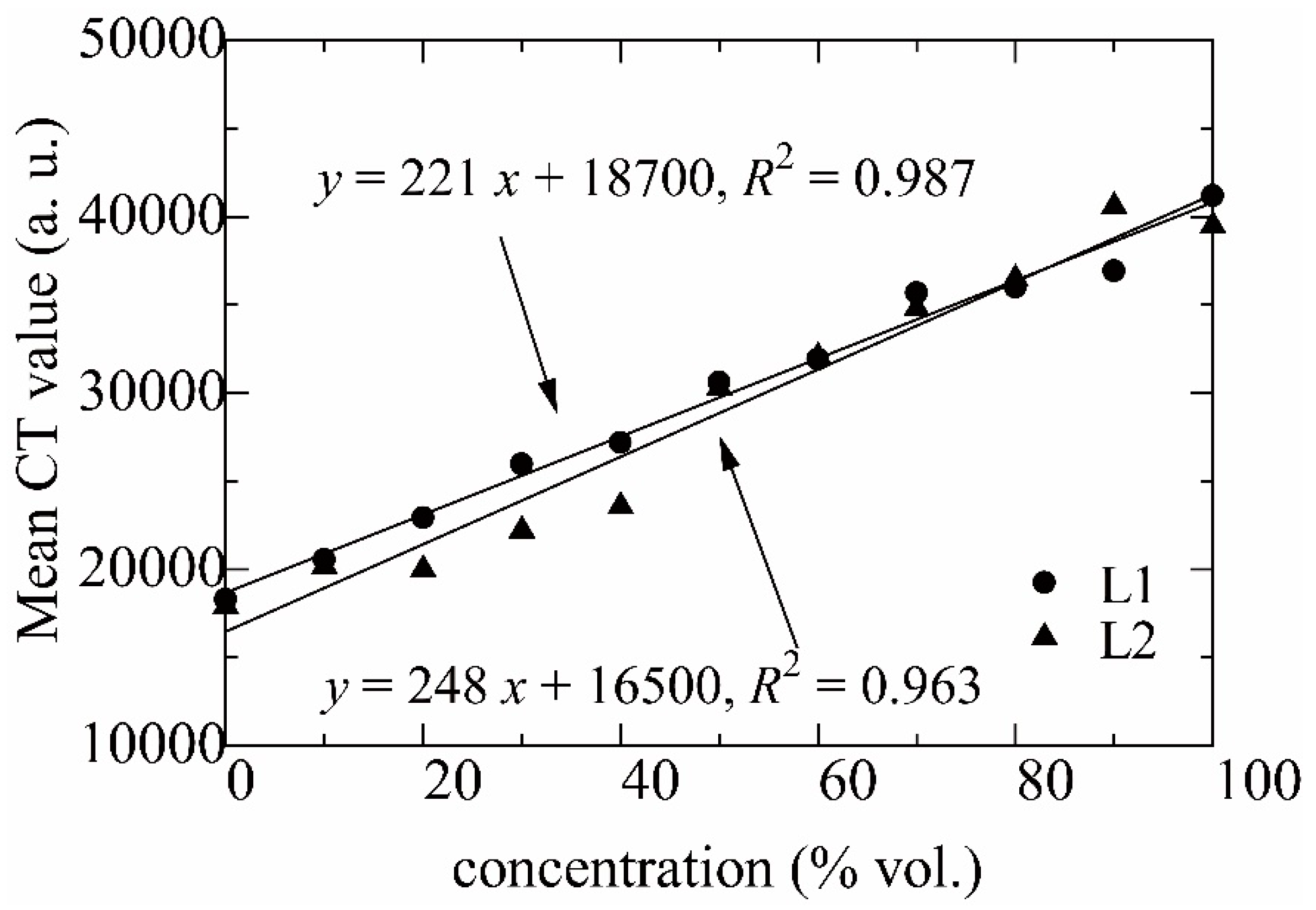
To facilitate further analysis, the CT values were converted to concentrations of the LVF. Eleven samples were prepared for each of L1 and L2 to obtain calibration curves for relating the CT values to concentrations. The samples consisted of a cylinder of porous medium saturated with a solution of the LVF in M1, ranging from 0 to 100 vol.% of the LVF at intervals of 10 vol.%. The calibration curves relating the CT values to concentrations of each LVF are displayed in Figure 2. Evidently, both parameters are related by a linear relationship. After converting the CT values to concentration values, a color profile was applied to the images to assess the development and patterns of viscous fingering. Finally, a 3D view of the finger structures was obtained by a commercial software (Volume Graphics, VG Studio Max, ver. 2.1).

3. Results and Discussion

3.1. Three-Dimensional Structure

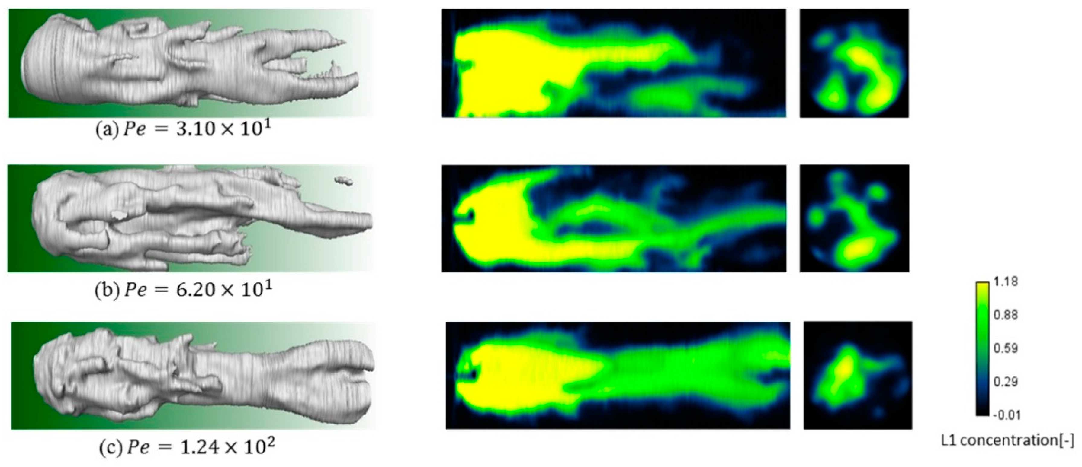
Figure 3 depicts the 3D structures of viscous fingering without gravity. In the absence of a density difference, pure viscous fingering occurred in the packed bed. After the injection of an LVF, a complex interaction between both fluids produced finger structures due to the viscosity difference, creating an irregular front between the fluids. The diameter of fingers was in the range of millimeters and extended over several pores. The fingers developed in a mean flow direction, maintaining a straight trajectory. The extension of the finger to the exit boundary caused breakthrough. Some interactions observed in 2D visualization of Hele-Shaw cells like tip-splitting and coalescence of fingers were noticed. Shielding, involving growth hindrance of smaller fingers by adjacent larger fingers are also discernible. The concentrations of the LVF decreased gradually along the fingers, and because of the constant viscosity ratio, the fingering structures for three Péclet numbers were similar. In our previous study [23], fine finger structures appeared with an increase in Péclet number. As the variation in Péclet number in the present study is small, change in the structures with Péclet number is inconspicuous.
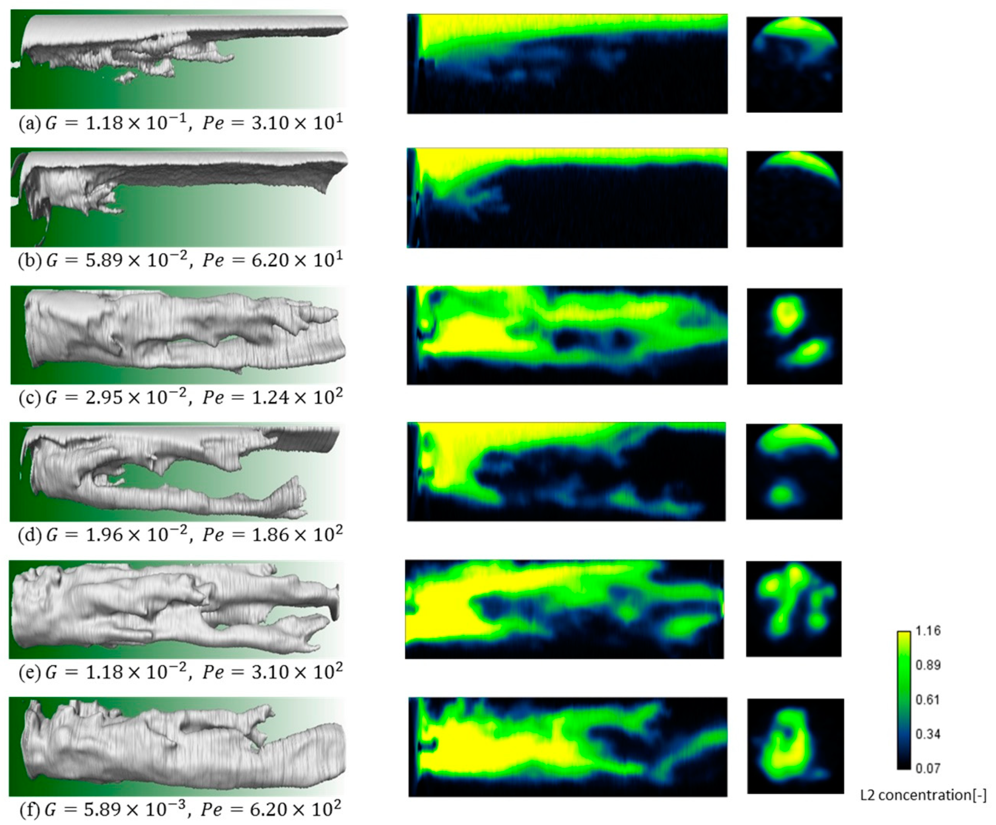
In the presence of density difference (Figure 4), similar viscous fingering is observed at low gravity numbers (Figure 4e,f), with nonlinear interactions like tip-splitting, coalescence, and shielding. Compared with Figure 3, the difference in structure is unclear, despite the difference in the viscosity ratio, and the concentrations of LVF in the fingers are not inclined toward the top side. A gravitational tongue extending below the top of the packed cylinder wall occurs at a G of 1.96 × 10⁻² (Figure 4d). The other branch of the finger extends directly below the finger with the gravitational tongue, with negligible influence of gravity. The concentration of LVF in the gravitational tongue was obviously higher compared with that in the finger. At high Gs of 1.18 × 10⁻¹ (Figure 4a) and 5.89 × 10⁻² (Figure 4b), clear gravitational tongues extend from the inlet to the outlet, but viscous fingering was only observed around the inlet. Since the injected LVF runs mostly along the gravitational tongue, a smaller amount of LVF contributes in the viscous fingering structure growth. The concentration of LVF increases in the gravitational tongue (Figure 4a,b,d) as the position gets closer to the top wall in the gravity direction.

3.2. Concentration Profiles and the Center of Gravity of LVF

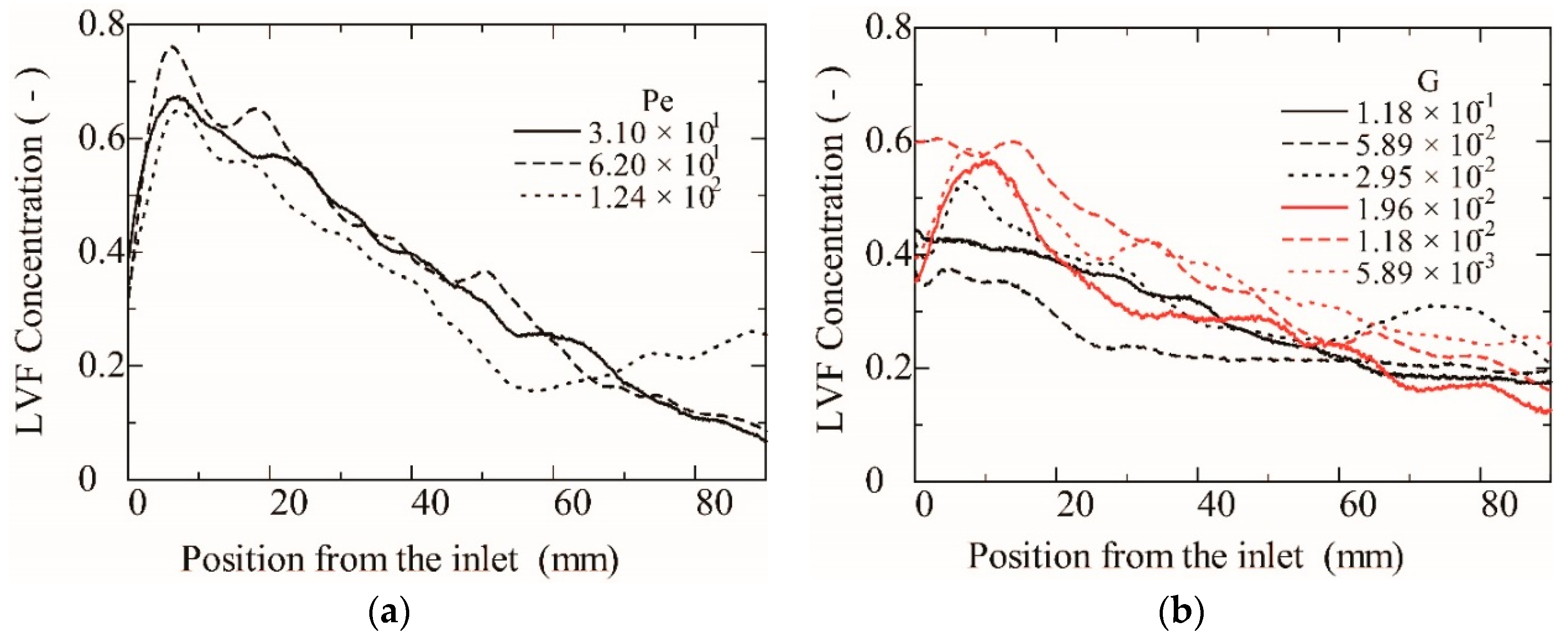
Averaged concentration in the cross-section transverse to the flow direction is shown in Figure 5. Without gravity, the average concentration decreases linearly from 0.6 to 0.8 at the inlet to 0.1–0.3 at the exit for all Péclet numbers. The reduction in the concentration at the position between 0 and 5 mm results from the point injection and partially from the measurement error associated with the cone beam CT, where the X-ray angle to the rotation axis deviates slightly from the right angle at the edge of images. These concentration profiles agree well with our previous results [23] for an M of 47.5. With gravity, the average concentration near the inlet reduces with increase in the gravity number, and the concentration profile tends to be flat. The average concentration at the gravitational tongue, i.e., the downstream part for high Gs of 1.18 × 10⁻¹ and 5.89 × 10⁻² is almost constant at 0.2.
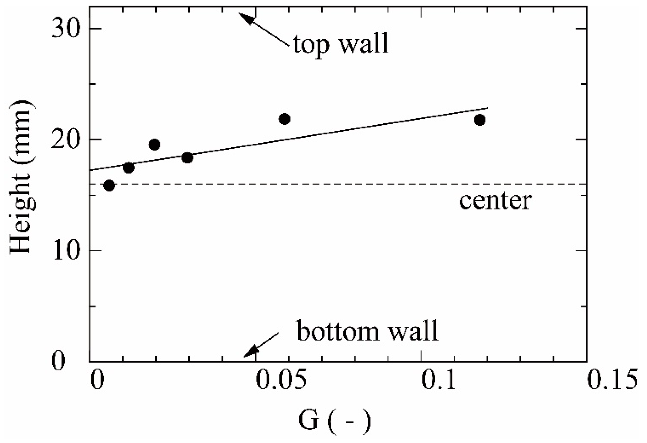
To quantitatively evaluate the development of the gravitational tongue, the center of gravity of the LVF was estimated. The concentration of the LVF in the cross-section perpendicular to the height of the cylinder from the inlet to the outlet was averaged. Then, the center of gravity of the LVF was estimated in the cross-section. Figure 6 shows the position of the center of gravity, where the height is defined by the distance from the bottom of the cylinder. The center of gravity is around the center of the cylinder (16 mm) for a low gravity number and shifts close to the top wall (32 mm) with an increase in the gravity number.

3.3. Displacement Efficiency

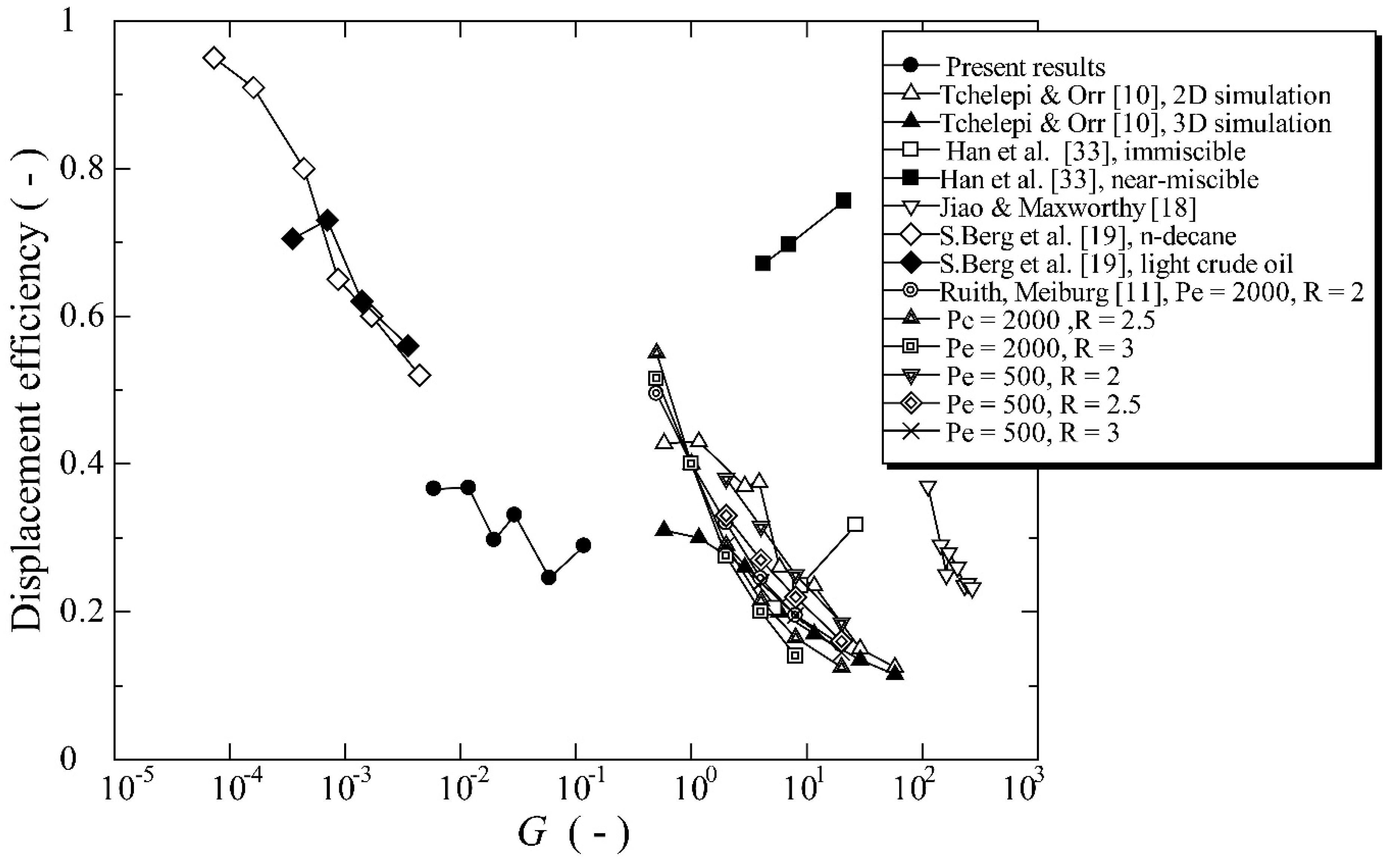
We define displacement efficiency as the produced MVF from the injection of 0.3 PV of LVF. Figure 7 shows the relation between the displacement efficiency and the gravity number from various numerical simulations and experiments [10,11,18,19,33]. In the present experiments, the displacement efficiency decreases from 0.37 to about 0.2 as the gravity number increases. At low Gs of 5.89 × 10⁻³ and 1.18 × 10⁻², the displacement efficiency is like that without gravity, showing values of 0.36, 0.37, and 0.34, for Péclet numbers of 3.10 × 101, 6.20 × 101, and 1.24 × 10², respectively, despite the difference in the M of 52.1 without gravity and 119 with gravity. In 2D or 3D numerical simulations [10,11], the displacement efficiency, defined at breakthrough, decreases with increasing gravity number. As the displacement efficiency without gravity depends on many factors, including the viscosity ratio, Péclet number, properties of the porous media, etc., the highest displacement efficiency with gravity changes with conditions. The displacement efficiency obtained for a Hele-Shaw cell with miscible fluids also decreases with increasing gravity number [18]. Berg et al. [19] proposed a novel enhanced oil recovery (EOR) scheme by performing flooding experiments with Berea sandstone cores, using less viscous and dense carbon disulfide to displace n-decane and light crude oil [19]. The displacement efficiency decreases with increasing gravity factor because of the gravity underrun of the carbon disulfide. Han et al. [33] performed CO2 EOR experiments with a Berea sandstone plate at immiscible and near-miscible conditions. They attributed the decrease in displacement efficiency with decreasing gravity number to increasing injection velocity causing reduction in the contact time between the fluids. The displacement efficiency overwhelmingly decreases with increasing gravity number, with the highest value achieved without gravity. However, it depends on many factors, including the viscosity ratio and Péclet number.

4. Conclusions

In this study, the three-dimensional structure of fingering at the viscous fingering to gravitational segregation boundary was observed using by X-ray microtography in a packed bed of particles. The findings are summarized as follows:
  • At a low gravity number, viscous fingering like that without gravity occurs showing nonlinear interactions like tip-splitting, shielding, and coalescence.
  • At a moderate gravity number, the gravitational tongue and viscous fingering appeared simultaneously, and the concentration of LVF in the gravitational tongue was higher than that in the finger.
  • At a high gravity number, a clear gravitational tongue penetrated from the inlet to the outlet, whereas viscous fingering was only observed around the inlet. In the gravitational tongue, the concentration of LVF increases as the position gets closer to the top wall in the gravity direction.
  • The averaged concentration near the inlet reduces with an increase in the gravity number and is characterized by a flat concentration profile. The average concentration at the gravitational tongue was almost constant at 0.2.
  • The displacement efficiency decreases with the gravity number from the highest value achieved without gravity but depends on many factors, including the viscosity ratio and Péclet number.

Author Contributions

Conceptualization, T.S.; investigation, T.S., T.K., and P.M.B.; data curation, T.K. and P.M.B.; writing—original draft preparation, P.M.B.; writing—review and editing, T.S.; visualization, T.K.

Funding

This research was funded by the JSPS KAKENHI Grant No. 17H00790.

Conflicts of Interest

The authors declare no conflict of interest.

References

  1. Homsy, G.M. Viscous Fingering in Porous Media. Annu. Rev. Fluid Mech. 1987, 19, 271–311. [Google Scholar] [CrossRef]
  2. Kueper, B.H.; Frind, E.O. An overview of immiscible fingering in porous media. J. Contam. Hydrol. 1988, 2, 95–110. [Google Scholar] [CrossRef]
  3. McCloud, K.; Maher, J. Experimental perturbations to Saffman-Taylor flow. Phys. Rep. 1995, 260, 139–185. [Google Scholar] [CrossRef]
  4. Hill, S.; Inst, P.F. Channeling in packed columns. Chem. Eng. Sci. 1952, 1, 247–253. [Google Scholar] [CrossRef]
  5. Saffman, P.G.; Taylor, G.I. The penetration of a fluid into a porous medium or Hele-Shaw cell containing a more viscous liquid. Proc. R. Soc. Lond. Ser. A. Math. Phys. Sci. 1958, 245, 312–329. [Google Scholar]
  6. Blackwell, R.J.; Rayne, J.R.; Terry, W.M. Factors influencing the efficiency of miscible displacement. Petrol. Trans. AIME 1959, 217, 1–8. [Google Scholar]
  7. Casademunt, J. Viscous fingering as a paradigm of interfacial pattern formation: Recent results and new challenges. Chaos Interdiscip. J. Nonlinear Sci. 2004, 14, 809. [Google Scholar] [CrossRef]
  8. Sahimi, M. Flow phenomena in rocks: From continuum models to fractals, percolation, cellular automata, and simulated annealing. Rev. Mod. Phys. 1993, 65, 1393–1534. [Google Scholar] [CrossRef]
  9. Fayers, F.J.; Muggeridge, A.H. Extensions to Dietz Theory and Behavior of Gravity Tongues in Slightly Tilted Reservoirs. SPE Reserv. Eng. 1990, 5, 487–494. [Google Scholar] [CrossRef]
  10. Tchelepi, H.A.; Orr, F.M., Jr. Interaction of viscous fingering, permeability heterogeneity, and gravity segregation in three dimensions. SPE Reserv. Eng. 1994, 9, 266–271. [Google Scholar] [CrossRef]
  11. Ruith, M.; Meiburg, E. Miscible rectilinear displacements with gravity override. Part 1. Homogeneous porous medium. J. Fluid Mech. 2000, 420, 225–257. [Google Scholar] [CrossRef]
  12. Camhi, E.; Meiburg, E.; Ruith, M. Miscible rectilinear displacements with gravity override. Part 2 Heterogeneous porous media. J. Fluid Mech. 2000, 420, 259–276. [Google Scholar] [CrossRef]
  13. Riaz, A.; Tchelepi, H.A. Numerical simulation of immiscible two-phase flow in porous media. Phys. Fluids 2006, 18, 014104. [Google Scholar] [CrossRef]
  14. Riaz, A.; Meiburg, E. Three-dimensional miscible displacement simulations in homogeneous porous media with gravity override. J. Fluid Mech. 2003, 494, 95–117. [Google Scholar] [CrossRef] [Green Version]
  15. Moortgat, J. Viscous and gravitational fingering in multiphase compositional and compressible flow. Adv. Water Resour. 2016, 89, 53–66. [Google Scholar] [CrossRef] [Green Version]
  16. Muggeridge, A.; Cockin, A.; Webb, K.; Frampton, H.; Collins, I.; Moulds, T.; Salino, P. Recovery rates, enhanced oil recovery and technological limits. Philos. Trans. R. Soc. 2014, 372, 20120320. [Google Scholar] [CrossRef] [Green Version]
  17. Zhang, H.; Sorbie, K.; Tsibuklis, N.; Sorbie, K. Viscous fingering in five-spot experimental porous media: New experimental results and numerical simulation. Chem. Eng. Sci. 1997, 52, 37–54. [Google Scholar] [CrossRef]
  18. Jiao, C.; Maxworthy, T. An experimental study of miscible displacement with gravity-override and viscosity-contrast in a Hele Shaw cell. Exp. Fluids 2008, 44, 781–794. [Google Scholar] [CrossRef]
  19. Berg, S.; Oedai, S.; Landman, A.J.; Brussee, N.; Boele, M.; Valdez, R.; Van Gelder, K. Miscible displacement of oils by carbon disulfide in porous media: Experiments and analysis. Phys. Fluids 2010, 22, 113102. [Google Scholar] [CrossRef]
  20. Richardson, J.; Sangree, J.; Sneider, R. Oil Recovery by Gravity Segregation. J. Pet. Technol. 1989, 41, 581–582. [Google Scholar] [CrossRef]
  21. Berg, S.; Ott, H. Stability of CO2 –brine immiscible displacement. Int. J. Greenh. Gas Control 2012, 11, 188–203. [Google Scholar] [CrossRef]
  22. Kumar, A.; Kimbler, O.K. Effect of Dispersion, Gravitational Segregation, and Formation Stratification on the Recovery of Freshwater Stored in Saline Aquifers. Water Resour. Res. 1970, 6, 1689–1700. [Google Scholar] [CrossRef]
  23. Suekane, T.; Ono, J.; Hyodo, A.; Nagatsu, Y. Three-dimensional viscous fingering in miscible displacement in porous media. Phys. Rev. Fluids 2017, 2, 103902. [Google Scholar] [CrossRef]
  24. Nakanishi, Y.; Hyodo, A.; Wang, L.; Suekane, T. Experimental study of 3D Rayleigh–Taylor convection between miscible fluids in a porous medium. Adv. Water Resour. 2016, 97, 224–232. [Google Scholar] [CrossRef]
  25. Wang, L.; Nakanishi, Y.; Hyodo, A.; Suekane, T. Three-dimensional structure of natural convection in a porous medium: Effect of dispersion on finger structure. Int. J. Greenh. Gas Control 2016, 53, 274–283. [Google Scholar] [CrossRef]
  26. Sin, S.; Suekane, T.; Nagatsu, Y.; Patmonoaji, A. Three-dimensional visualization of viscous fingering for non-Newtonian fluids with chemical reactions that change viscosity. Phys. Rev. Fluids 2019, 4, 054502. [Google Scholar] [CrossRef]
  27. Jiang, L.; Liu, Y.; Yang, M.; Zhou, X.; Yu, M.; Zhang, Y.; Song, Y.; Xue, Z.; Suekane, T. Behavior of CO2/water flow in porous media for CO2 geological storage. Magn. Reson. Imaging 2016, 37, 100–106. [Google Scholar] [CrossRef]
  28. Suekane, T.; Furukawa, N.; Tsushima, S.; Hirai, S.; Kiyota, M. Application of MRI in the Measurement of Two-Phase Flow of Supercritical CO2 and Water in Porous Rocks. J. Porous Media 2009, 12, 143–154. [Google Scholar] [CrossRef]
  29. Suekane, T.; Soukawa, S.; Iwatani, S.; Tsushima, S.; Hirai, S. Behavior of supercritical CO2 injected into porous media containing water. Energy 2005, 30, 2370–2382. [Google Scholar] [CrossRef]
  30. Wang, L.; Nakanishi, Y.; Teston, A.D.; Suekane, T. Effect of diffusing layer thickness on the density-driven natural convection of miscible fluids in porous media: Modeling of mass transport. J. Fluid Sci. Technol. 2018, 13, 1–20. [Google Scholar] [CrossRef]
  31. Rasband, W.S. ImageJ U.S. National Institutes of Health, Bethesda, Maryland, USA. Available online: http://rsb.info.nih.gov/ij/ (accessed on 15 June 2019).
  32. Schneider, C.A.; Rasband, W.S.; Eliceiri, K.W. NIH Image to ImageJ: 25 years of image analysis. Nat. Methods 2012, 9, 671–675. [Google Scholar] [CrossRef]
  33. Han, J.; Lee, M.; Lee, W.; Lee, Y.; Sung, W. Effect of gravity segregation on CO2 sequestration and oil production during CO2 flooding. Appl. Energy 2016, 161, 85–91. [Google Scholar] [CrossRef]
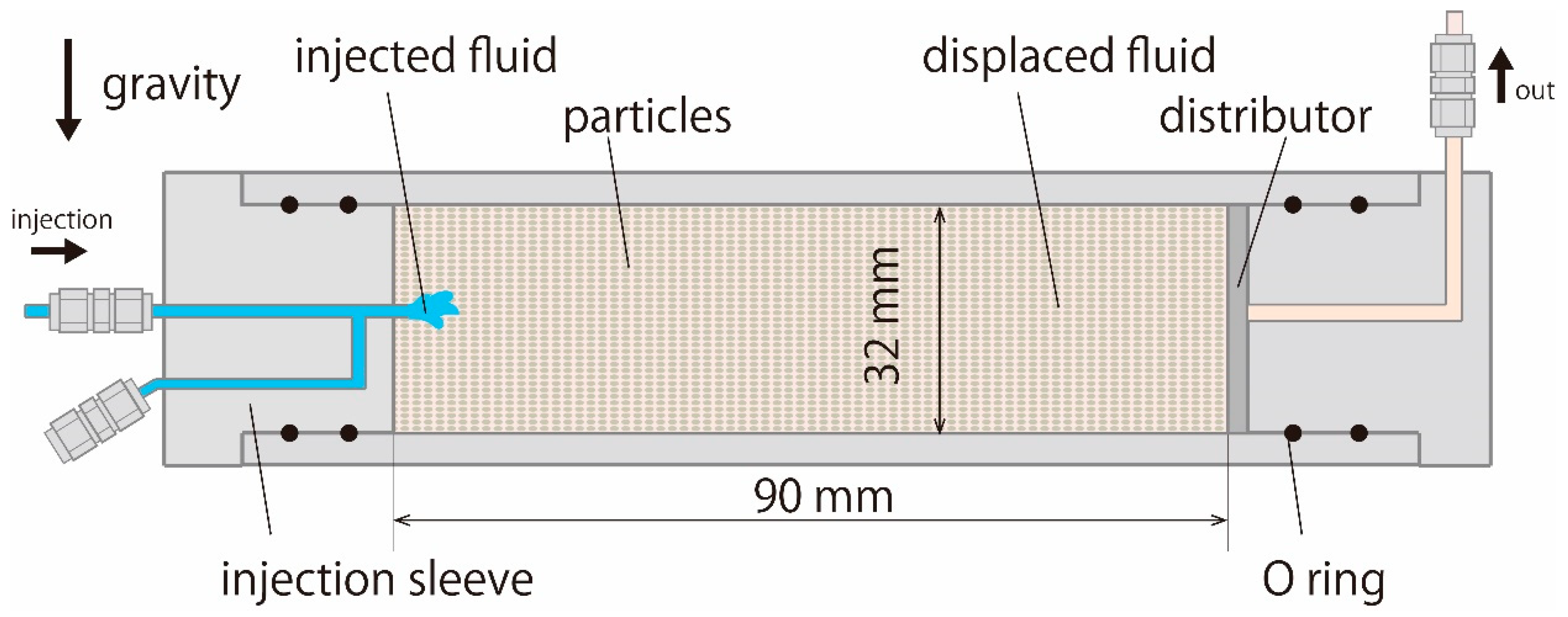
Figure 1. Cross-sectional view of a packed bed of particles. Melamine particles with an average diameter of 338 µm were packed in a tube with an inner diameter of 32 mm and over 90 mm in height. The diameter of the inlet nozzle is 1.59 mm (1/16 in). A sintered glass plate placed at the exit serves as a distributor.
Fluids 04 00130 g001
Figure 2. Calibration curves between the concentration of LVF and X-ray computer tomography (CT) value.
Fluids 04 00130 g002
Figure 3. Left: Structure of fingering patterns at the LVF injection of 0.3 PV without density difference. Iso-contour surfaces corresponding to a 20 vol.% concentration of LVF were visible Center: Concentration of LVF in a vertical cross-section through the axis of the cylinder. Right: Concentration of LVF in a vertical cross-section at the center, between the inlet and the outlet.
Fluids 04 00130 g003
Figure 4. Left: Structure of fingering patterns at the LVF injection of 0.3 pore volume (PV) with density difference. Iso-contour surfaces corresponding to a 20 vol.% concentration of LVF are visible. Center: Concentration of LVF in a vertical cross-section through the axis of the cylinder. Right: Concentration of LVF in a vertical cross-section at the center between the inlet and the outlet.
Fluids 04 00130 g004
Figure 5. Concentration profiles in a flow direction (a) without gravity for three different Péclet numbers and (b) with gravity at various gravity numbers. The distance from the inlet in a flow direction is represented on the horizontal axis.
Fluids 04 00130 g005
Figure 6. Deviation of the position of the center of gravity of an LVF with gravity number.
Fluids 04 00130 g006
Figure 7. Displacement efficiency vs. the gravity number. Tchelepi and Orr [10], recovery at breakthrough obtained by two-dimensional and three-dimensional numerical simulations Ruith and Meiburg [11], recovery at the breakthrough obtained by two-dimensional numerical simulations. R is the parameter relates the viscosity and concentration. Jiao and Maxworthy [18], miscible flow in a Hele-Shaw cell. Berg et al. [19], n-decane and light crude oil displaced by carbon disulfide in Berea sandstone core at one PV injection. Han et al. [33], n-decane displaced by CO2 at immiscible and near-miscible condition in a Berea sandstone plate.
Fluids 04 00130 g007
Table 1. Properties of the fluids used in the experiments.
FluidsCompositionDensity ρ (kg/m3)Viscosity 1 μ (mPa·s)
M1Glycerol solution
85 wt.% glycerol
1.21 × 103138
L1NaI + NaCl solution
7.85 wt.% NaI
21.5 wt.% NaCl
1.21 × 1032.63
L2NaI solution
10 wt.% NaI
1.07 × 1031.16
1 Estimated by the tuning fork vibration viscometer (A and D Co., Tokyo, Japan, SV-10H) t 23.2 °C.
Table 2. Experimental conditions for various sets of more viscous fluids (MVFs) and less viscous fluids (LVFs) tested.
FluidsPeDarcy Velocity
v (m/s)
Viscosity Ratio
M
Density Difference
Δρ (kg/m3)
G
M1-L1 3.10 × 10 1 4.68 × 10 6 52.500
6.20 × 10 1 9.35 × 10 6
1.24 × 10 2 1.87 × 10 5
M1-L2 3.10 × 10 1 4.68 × 10 6 119140 1.18 × 10 1
6.20 × 10 1 9.35 × 10 6 5.89 × 10 2
1.24 × 10 2 1.87 × 10 5 2.95 × 10 2
1.86 × 10 2 2.81 × 10 5 1.96 × 10 2
3.10 × 10 2 4.68 × 10 5 1.18 × 10 2
6.20 × 10 2 9.35 × 10 5 5.89 × 10 3