Abstract
Darrieus-type Vertical Axis Wind Turbines (VAWT) are promising for small scale decentralized power generation because of their unique advantages such as simple design, insensitive to wind direction, reliability, and ease of maintenance. Despite these positive aspects, poor self-starting capability and low efficiency in weak and unsteady winds deteriorate further development. Adaptive Hybrid Darrieus Turbine (AHDT) was proposed by the author in the past study as a potential solution to enhance low wind speed characteristics. The objective of the current research is to optimize the parameters of AHDT. AHDT integrates a dynamically varying Savonius rotor with a Darrieus rotor. A fully detailed 2D numerical study employing Reynold-Averaged Navier Stokes (RANS) is carried out to investigate the impact of the Darrieus rotor diameter (DR) on the Savonius rotor (DT) with regard to hybrid turbine performance. The power coefficient of the Darrieus rotor is evaluated when the Savonius rotor is in the closed condition (cylinder) of various diameters. The influence of Reynolds number (Re) on the torque coefficient is examined. Power loss of 58.3% and 25% is reported for DR/DT ratio of 1.5 and 2 respectively for AHDT with solidity 0.5 at 9 m/s. The flow interaction between the Savonius rotor in closed configuration reveals the formation of von Karman vortices that interact with Darrieus blades resulting in flow detachment. An optimum diametrical ratio (DR/DT) of 3 is found to yield the maximum power coefficient of the Darrieus rotor.
1. Introduction
The insatiable hunger for energy and the mass burning of fossil fuels has shifted the focus towards clean energy sources. Wind energy, being the key source among renewable energies, saw tremendous growth in the past decades with a total installed capacity of 591 GW as of 2018 [1]. The rapid development of wind turbine technology has sprouted interest in different wind turbines apart from Horizontal Axis Wind Turbine (HAWT). Advancements in energy storage technologies and decentralized power generation have renewed interest in VAWTs. They are especially suitable for small-scale power generation because of their niche advantages such as being insensitive to wind direction, ease of maintenance, reliability, aesthetics, and low noise. Among various types of VAWT, Darrieus and Savonius types are popular as they are lucrative from an economic perspective. These turbines are especially suited for the urban environment and rooftop installations, as they are able to generate power in turbulent winds [2]. Savonius turbine operates by the difference in the aerodynamic drag between the concave and convex side of the buckets [3]. These turbines are able to start at low wind speed and generate substantial power. As per IEC 61400-2 [4], wind speed is considered to be low (Class IV) if the annual average wind speed at a specific location is below 7.5 m/s. Notable drawbacks include low efficiency and high wind loads demanding heavier support structures. Myriad studies have been carried out in the past, unfolding the flow pattern around the Savonius buckets and its blade wake interactions [5]. Numerous experimental studies established the critical parameters of the turbine such as the effect of end plates; optimum end plate diameters; the effect of aspect ratio; the influence of bucket spacing; bucket overlap; number of buckets; number of stages; interference of shat; and the effect of deflecting plate and helical and straight blades. Telescopic Savonius Turbine (TST) was proposed by Mohan [6] to avert the wind load at high winds. The numerical study concludes that the wind load can be reduced by up to 60% compared to the conventional Savonius turbine [7]. Darrieus turbine is known for its high efficiency among VAWTs as they operate by lift force, but they are notorious for their poor self-starting capability and low efficiency at weak wind flows. The helical turbine was proposed by Gorlov in 1995 [8]. Compared to the straight-bladed turbine, the helical-bladed turbine offers noteworthy advantages such as enhanced self-starting capability, low noise, increased blade life, low vibrations, and reduced peak stress in the blades [9]. The self-starting capability is improved by the reduction of Angle of Attack (AoA) and the ability of the blades to accelerate beyond the dead band [10].
It is also evident from the past studies that the stall angle is increased due to the boundary layer attachment by the introduction of spanwise flow by the helical blades. Tailored airfoils are proposed to delay stall [11]. Trapped vortex airfoil was conceived to delay the flow attachment by trapping a vortex bubble [12]. The numerical study reveals that the trapped bubble is unstable due to high AoA [13]. The J-profile blade is introduced to exploit the drag force and to reduce the blade manufacturing cost. Nested Darrieus rotor was attempted to increase the startup torque, but they induce vibrations on the downwind half due to turbulent wake downstream [14]. High solidity blades are able to increase the starting torque but the peak power coefficient is reduced significantly. Airfoils with a modified trailing edge were anticipated to provide an early start [15]. The cavity introduced on the trailing edge on the blade does improve the performance at low winds but suffers from reduced lift at high Tip Speed Ratio (TSR). Hybrid Savonius–Darrieus rotor demonstrates improved low wind behaviour but limits the operating TSR range to 1.2 on the combined machine [16]. The electrical startup was investigated to start the Darrieus rotor in low wind speed by accelerating beyond the dead band [17]. Innovative electronics convert the generator to a motor at low winds and operate as a conventional generator after reaching a critical rpm. Though the solution is attractive, the frequent starting due to intermittent wind consumes significant power leading to decreased annual energy yield. Blade pitching [18] was proposed to increase low wind performance as blades are constantly moved to optimum AoA. Despite improved overall performance, the blade pitching systems are not lucrative for a small wind turbine due to its complexity. Ducted Darrieus turbines have been experimented to accelerate the wind flow before it reaches the rotor [19]. The wind loads and cost of support structures hinders any further development on that front.
The Savonius turbines are known for their higher starting torque, while the Darrieus turbines are notorious for poor starting torque. Obviously, the curious question is how to combine both the rotors to supplement each other. At low wind speeds (<3 m/s), the combined machine demonstrates the characteristics of a Savonius rotor, while at high winds (>4 m/s), the combined machine will behave as a conventional Darrieus rotor. Two configurations are practically feasible to combine a Savonius and Darrieus rotor. The Savonius rotor can be placed either above or below the Darrieus rotor, or the Savonius rotor can be nested inside the Darrieus rotor. The placement of the Savonius rotor outside the Darrieus rotor tends to increase the length of the rotating shaft, which in turn will lead to vibrations. Hence, the pragmatic method is to nest the Savonius rotor within the Darrieus rotor. Based on the above idea, a number of past studies [20] have been conducted both experimentally and computationally. The objective of all these studies is to optimize the Savonius rotor diameter for maximum low wind performance and to maintain the Cp of the Darrieus rotor at high winds by minimizing the effect of the Savonius rotor [21]. The results show that the starting torque of the combined machine is much higher than the Darrieus rotor, while the peak Cp is achieved at lower TSR. The maximum operating TSR for the combined machine is 1–1.2 [22]. It has to be noted that the maximum TSR for a Savonius rotor is 1, and any attempt to operate beyond TSR 1 will generate negative torque. The Darrieus rotor operates at TSR 3–6. This mismatch between the peak performance of two rotors is a crucial problem limiting the further development of these hybrid turbines [23]. All the concepts so far discussed are successful in improving the low wind behaviour to some extent, but severely degrade the performance at high winds. Innovative AHDT is proposed as an economically feasible solution with an early start and minimal impact on the Darrieus rotor by exploiting the merits of both the turbines.
2. State of art of Computational Simulations on VAWT
The renewed interest in the Darrieus turbines has resulted in intense research which has led to further understanding of the behaviors of the rotor. The dynamic stall has been studied in detail by Buchner by comparing the simulation and experiment. Simao [24] conducted a Particle Velocity Interferometry (PIV) visualization during the dynamic stall on the rotor. Flow curvature effects and angle of incidence was studied by Bianchini [25]. Blade wake interactions and the unsteady effects were investigated by Ragni [26]. High fidelity CFD simulations on the Darrieus rotor were performed by Balduzzi [27]. The effect of pitch angle on the performance of the Darrieus rotor and the associated aerodynamics were examined by Kalkman [28]. New airfoils have been proposed to lower the manufacturing cost such as NTU-20-V and can computationally be compared with NACA 0018 [29]. A similar study on the performance of the Darrieus turbine under different shaft diameters was carried out by Rezaeiha [30].
3. Overview of Adaptive Hybrid Darrieus Turbine
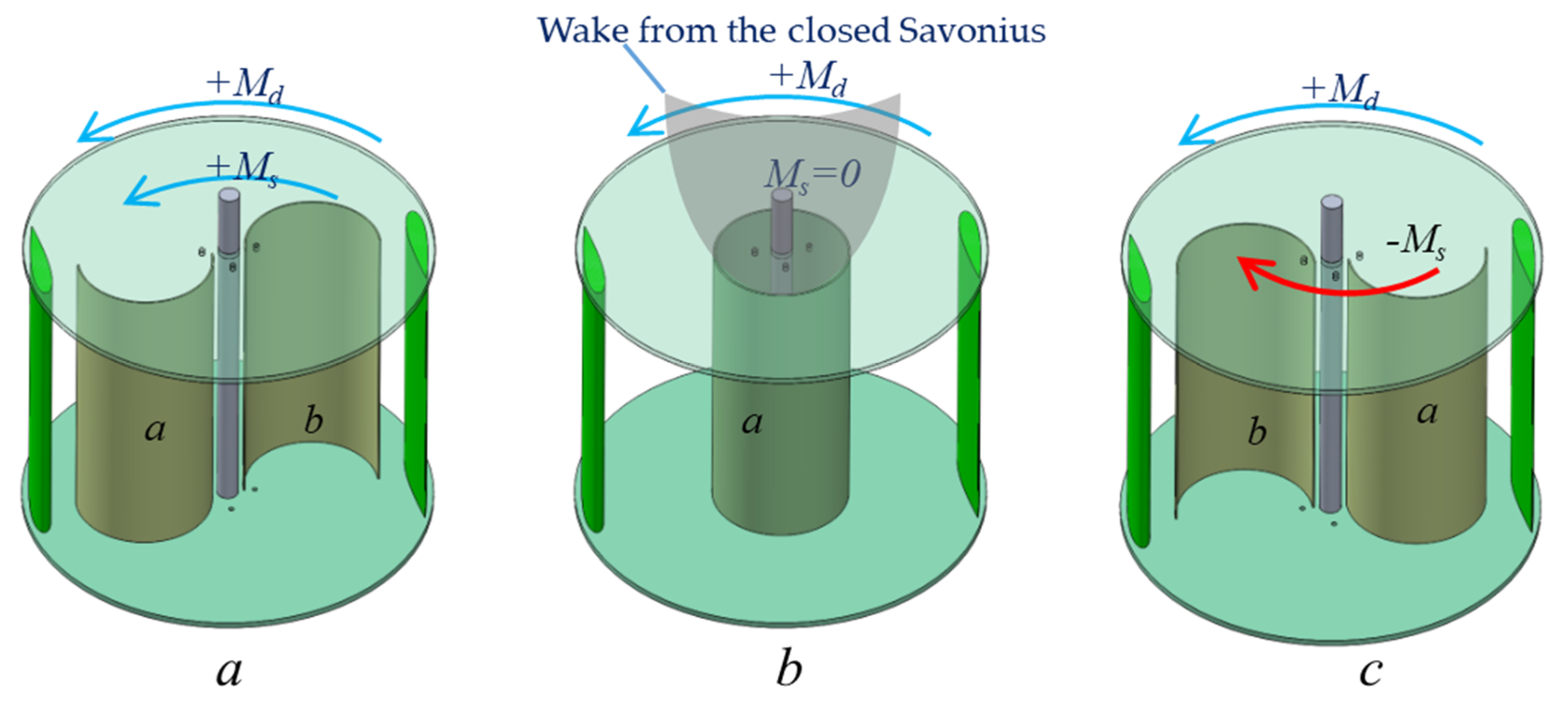
A hybrid Savonius–Darrieus turbine was proposed in the 1980s, as the two-bladed phi rotor suffers from poor self-starting capability. Another important challenge that hinders the development of the Darrieus rotor is the over-speeding of the turbine. Several FloWind turbines crashed to the ground due to inability of the turbines to limit their speed. The catastrophic failures of Flowind turbines (FloWind Corp., Tehachapi, CA, USA) has brought about deep concerns regarding the suitability of the Darrieus rotor for wind power generation. How to overcome poor self-starting capability and over-speeding are the two critical questions that have remained unanswered for these many years. A single solution to the above said questions conflicts each other, as enhancing the startup capability at a low wind speed will eventually lead to over-speeding at high winds. Though a Hybrid Savonius–Darrieus turbine is a potential solution to increase the starting torque, it drastically increases the wind loads and the over-speeding issues. The conventional hybrid turbine has a common shaft for Savonius and Darrieus rotors. The strategy is to employ the drag torque generated by a Savonius rotor to accelerate the Darrieus rotor. The optimum TSR for a two-bladed Darrieus rotor lies between 3 to 5 and the optimum TSR for Savonius rotor is 1 [31]. The Savonius rotor tends to generate resistive torque and in fact energy must be expended to rotate the Savonius rotor for a TSR above 1. The mismatch between the optimum TSR for the two rotors severely degrades the performance at higher TSR. Practically, a conventional hybrid Darrius-Savonius rotor will not accelerate beyond 1.5, resulting in an iota of improvement in annual energy output. Hence, a novel design has been put forward to minimize the influence of the Savonius rotor beyond a TSR of 1. The strategy is to transform the Savonius rotor into a shape that leaves minimum wake downstream without any resistive torque at higher TSR. A two bucket Savonius rotor can be transformed into a nominal cylinder if they are able to slide. The wake behind the downstream is axisymmetric with minimum width compared to other shapes. The wake width and the kinetic energy imbibed dictate the performance of the Darrieus rotor. A two-stage two bucket Savonius rotor offset at 90° can improve the directional starting. The three operating configurations are shown in Figure 1a–c. At low wind speed, the Darrieus rotor torque () and Savonius rotor torque are in the same direction when the Savonius buckets a and b are arranged as shown in Figure 1a.
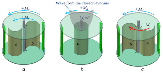
Figure 1.
(a) Adaptive Hybrid Darrieus Turbine (AHDT) rotor in open configuration (b) Closed configuration (c) Braking configuration.
As the TSR reaches 1, the buckets slide towards the axis of rotation to form a cylinder without any torque generation ), as shown in Figure 1b. In the extreme wind conditions and above the rated rotor rpm, the Savonius buckets slides in the opposite direction, generating resistive torque , decelerating the rotor as shown in Figure 1c. The number of blades on the Darrieus rotor, orientation of the rotor to the oncoming wind, angular offset between the Savonius buckets and the Darrieus rotor, and ratio between the diameters of Darrieus rotor to the Savonius rotor are the crucial design parameters that determine the starting characteristics. The angular offset between Darrieus blades and the Savonius buckets will have minimal impact on the performance, as two stages are arranged offset at 90°. Hence, from the structural perspective, the Savonius buckets can slide on the Darrieus blade, connecting struts and eliminating the requirement for additional structures. Thus, the AHDT has the capability to start the turbine at low wind speed, let it operate with minimal effect on the Darrieus rotor, and decelerate the rotor when it rotates beyond the rated rpm. The construction and mechanical arrangement are less complex making this concept commercially implementable. A double Multiple StreamTube model [32] employed for the performance assessment of the conventional Darrieus rotor is not applicable to predict the performance of AHDT, though the model was modified to include the Savonius rotor [33]. Hence, computational analysis will be a suitable process to initiate the optimization with the initial promising experimental results [34].
4. Computational Domain and Meshing
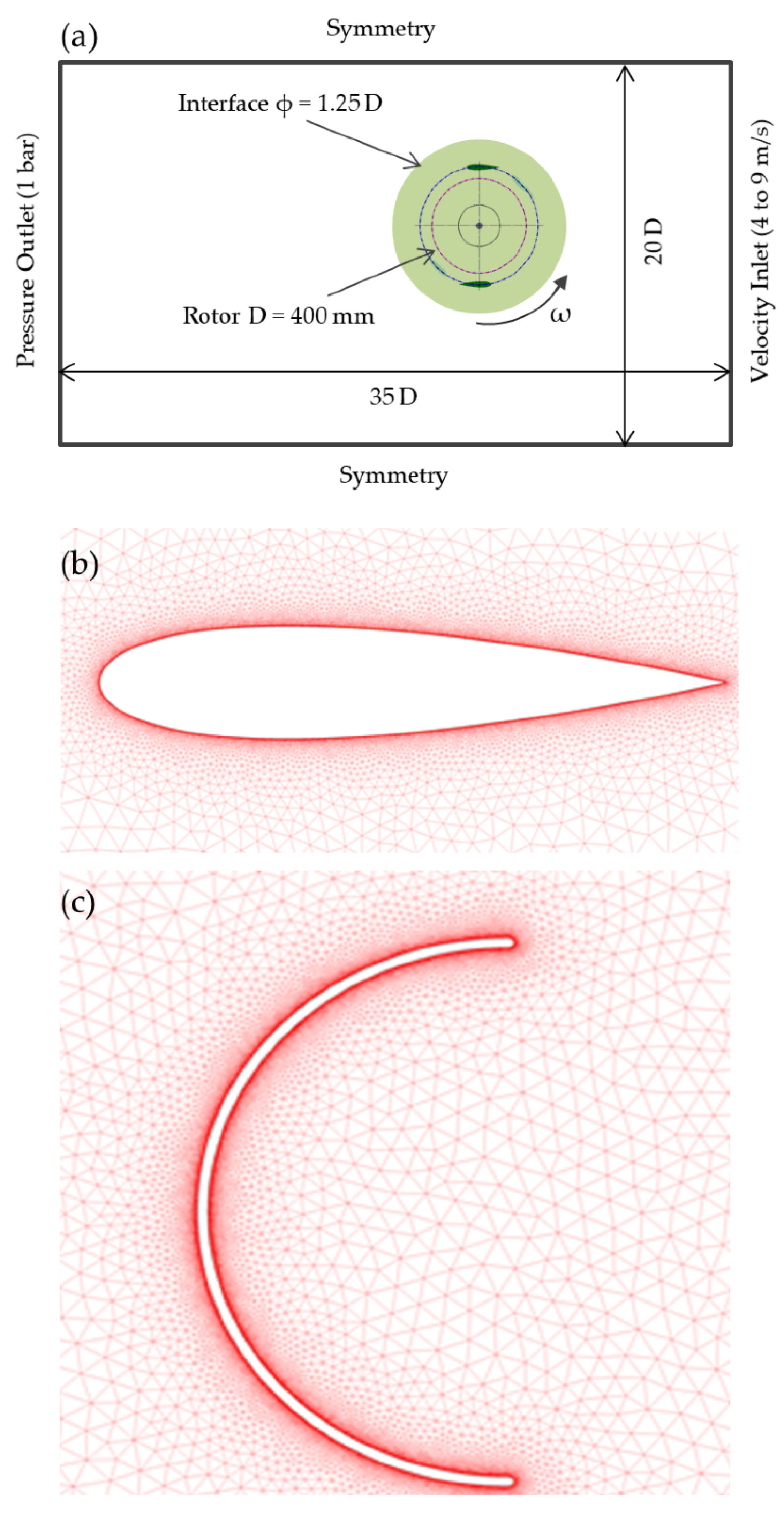
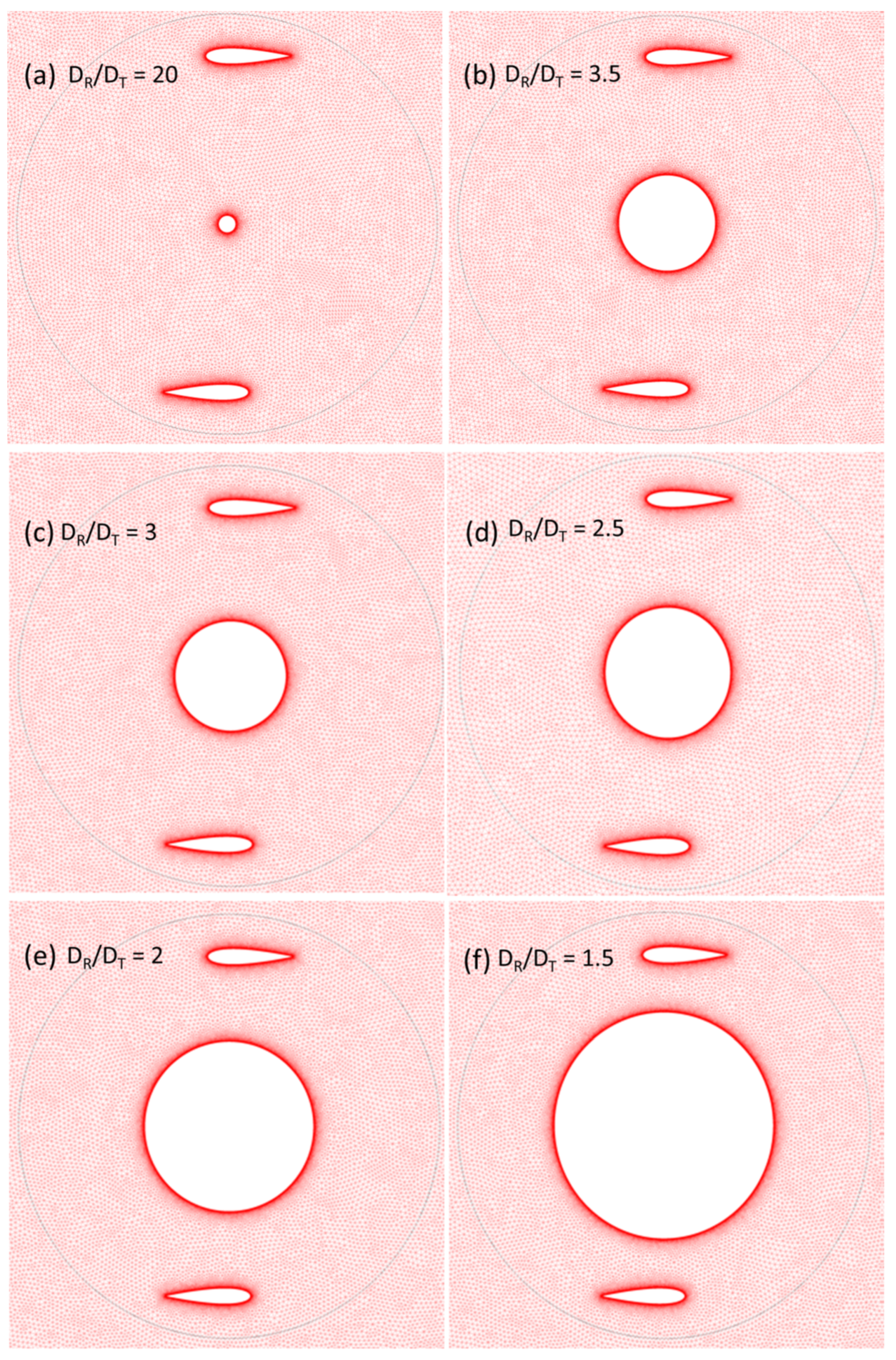
The guidelines for the computational simulations for this work are derived from a previous study [35]. It is vital to consider a larger domain size that represents the turbine operating in field conditions and to avoid the blockage. The computational domain is rectangular and of the size 20 D × 35 D, where D corresponds to the maximum rotor diameter (0.4 m in current study), and the rotor is placed at 10 D from the inlet boundary condition. In addition, the minimum domain size in all directions should be at least 20 times the rotor radius. The exit boundary condition is placed at a distance of 15 D downstream with respect to the rotor in order to allow a complete development of the wake structure. The inlet boundary has been set as a velocity inlet, while the outlet is set to a pressure outlet. The wind speed at the inlet varies from 4 m/s to 9 m/s. The pressure outlet has been assigned to an atmospheric pressure value. For the two side boundaries, symmetric boundary conditions have been used. To maintain the flow continuity in the field, the circular edge in the domain is set as an interface. In order to maintain the mesh linkage between the domain and the turbine, the circumferential edge of the turbine is also set as an interface. The rotating zone revolves at the same angular speed as the rotor, while the domain region is stationary. Since the flow is over a rotating solid, the sliding mesh technique has been used. Figure 2a shows the main geometric features and the CFD boundary conditions of the computational domain. A 2D unstructured mesh (triangular type) has been generated in the domain as well as in the rotating zone using ANSYS meshing tool as shown in Figure 2b,c. Much attention has been paid for the near wall treatment of the blades by generating cells of smaller sizes with an edge size setting of 0.1 mm. From the blade walls, the mesh cells grow evenly from smaller size topology to higher ones as seen in the Figure 3, thus adopting the appropriate cell size prevailing in the rotating zone. In the vicinity of the blade, structured mesh has been generated with y+ < 1 to capture the flow near the blades accurately.
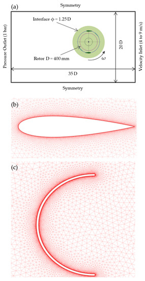
Figure 2.
(a) Domain Characteristics; (b) and (c) Mesh near blade walls.
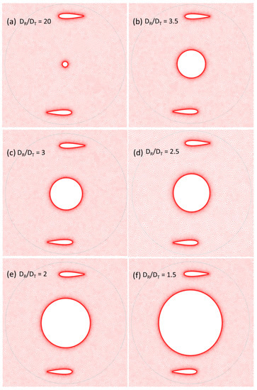
Figure 3.
Mesh display for various diametrical ratios.
5. Convergence Analysis
5.1. Grid Convergence Analysis
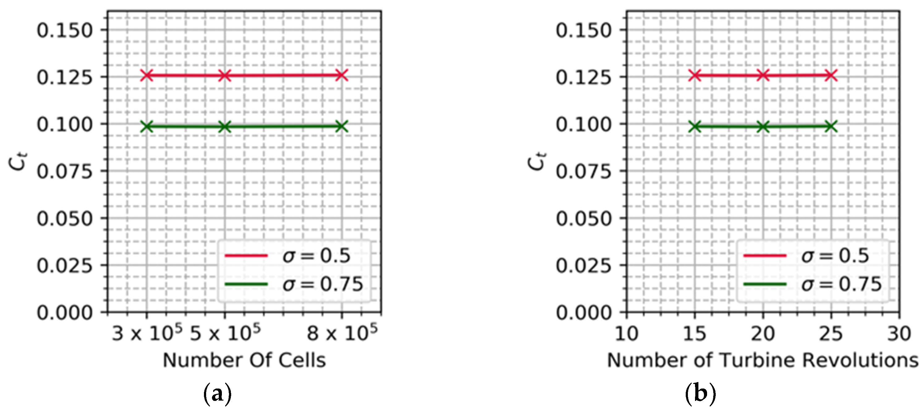
The computational results are highly dependent on the density of the grid. Mesh-independent results are imperative for accurate prediction and to compare with experimental outcomes. Coarse, medium and fine grids are generated with the cell count of 0.3, 0.5 and 0.8 million respectively. Though the conventional method is to systematically double the number of cells following established methods such as grid systematic refinement, General Richardson Extrapolation (GRE) or Grid Convergence Index (GCI), the current study relies on prior similar studies of cell count to start with in order to reduce the computational time. The number of nodes on the airfoil surface is 1000 for the coarse grid, whereas for the fine grid it is improved to 4000 nodes to capture the complex flow, flow detachment and dynamic stall. The torque coefficient (Ct) is the primary parameter through which the power coefficient is obtained. It is defined as the ratio of generated aerodynamic torque to the available torque in the wind. Ct is computed by applying the RANS and the SST turbulence model for the selected grid sizes. Results depict that the difference in Ct value between 0.5 and 0.8 million cells is less than 1%. The same procedure is repeated for the two-bladed and three-bladed Darrieus rotors to confirm that the chosen mesh density is sufficient for a solidity of σ = 0.5 and σ = 0.75. Hence, the optimum cell count is concluded as 0.5 million, which will be followed for the rest of study. The Ct value against different cell counts is shown in Figure 4a.
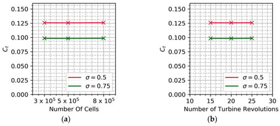
Figure 4.
(a) Grid independence study on different solidity. (b) Time step on different solidity.
5.2. Revolution Convergence Analysis
As the turbine starts to rotate, the flow over the turbine blades is highly unstable. After a few revolutions, the flow is stabilized at which the parameter of interest is measured. Finding the minimum number of revolutions for the given domain is imperative to keep the computational resources and time low. The number of revolutions at which the flow stabilizes is dictated by domain size, number of cells and boundary conditions. For the current test case, the Ct value is monitored over 30 revolutions. The turbine is allowed to rotate at a different TSR from 0.5 to 4, with the turbulent intensity and turbulent length scale fixed. Segregated pressure-based solver, known as a SIMPLE (Semi Implicit Method for Pressure Linked Equations) algorithm, is employed to execute the computation. The computation is initiated with a first order upwind scheme for spatial and temporal discretization followed by a second-order upwind scheme for accurate predictions. The time step size is set to 5 × 10⁻⁴ s. Residual convergence criteria for each physical step is set to 10−5. The Ct is measured for each timestep and averaged over one revolution. The obtained Ct value is compared with the previous revolution to compute the difference and corresponding number of revolutions chosen if the difference is less than 0.02. The current run stabilizes after 20 revolutions and hence for further test cases, all the parameters of investigation are measured at 20 revolutions. The Ct value against the number of revolutions is shown in Figure 4b.
6. Mathematical Methodology
6.1. Reynolds Averaged Navier–Stokes Model
The Reynold-Averaged Navier–Stokes (RANS) method is the fastest CFD approach widely employed to solve the flow problems in wind turbines. The RANS models apply the eddy-viscosity model or Reynolds stress model to compute this Reynolds stress variable. Two equation models such as k-epsilon (k-ε), k-omega (k-ω) and k-ω SST are most widely used for wind turbines, where k is the turbulence kinetic energy per unit mass, epsilon is the specific dissipation, and ω is the specific dissipation rate. As mentioned before, the Navier–Stokes equations are very complex to solve directly due to their non-linear nature. This is due to the presence of convective acceleration terms. In order to approximate these equations, several numerical methods are available.
6.2. Turbulence Model
The k-ω SST model is a simpler way of representing the k-ω shear stress transport model which is the blend of k-ω and k-ε models. The k-ω SST model is the upgraded form of the baseline (BSL) model which varies linearly between k-ω and k-ε models. This model makes use of the k-ω definition in regions where the boundary layer predominates and the k-ε definition in regions outside the boundary layer. The transformed k-ω formulation from the k-ε model is given by
The newly transformed equations due to the combination of two models are represented by
The blending function F1 switches between the previously defined two methods in the desired regions. It is formulated in such a way that the near wake region marked the use of the k-ω model and the free shear layer makes use of the k-ε model. Equations (5) and (6) mention that the F1 term represents the blending function which makes use of both fluid and special terms,
The three factors mentioned in the above Equations (5)–(7) represent the viscous sub-layer, turbulent length scale and small free stream values. One of the major advantages of the k-ω SST model in comparison with the BSL model is that the turbulent shear stress is accounted for by limiting eddy viscosity. The turbulent shear stress is assumed to be proportional to specific turbulent kinetic energy in logarithmic and wake regions of the turbulent boundary layer. The major drawback of eddy viscosity and the Boussinesq hypothesis is that these models assume isotropic turbulence which would end up generating unrealistic results. k-ω SST is suitable for predicting the flow in the viscous sub-layer and in the regions away from the wall (wake region). In addition, the SST model is less sensitive to free stream conditions (flow outside the boundary layer) than many other turbulence models.
7. Results and Discussion
7.1. Torque Coefficient Comparison for Different (DR/DT)
CFD simulations for different Darrieus to closed Savonius rotor diameter ratios (DR/DT) are performed in search of the optimum rotor diameters. The AHDT in closed configuration is simulated for five complete revolutions instantaneously recording the torque coefficient of blades for every degree of rotation. However, the solution is converged after three revolutions of the turbine. The coefficient of power (Cp) is calculated from (Ct) as shown in Equation (9).
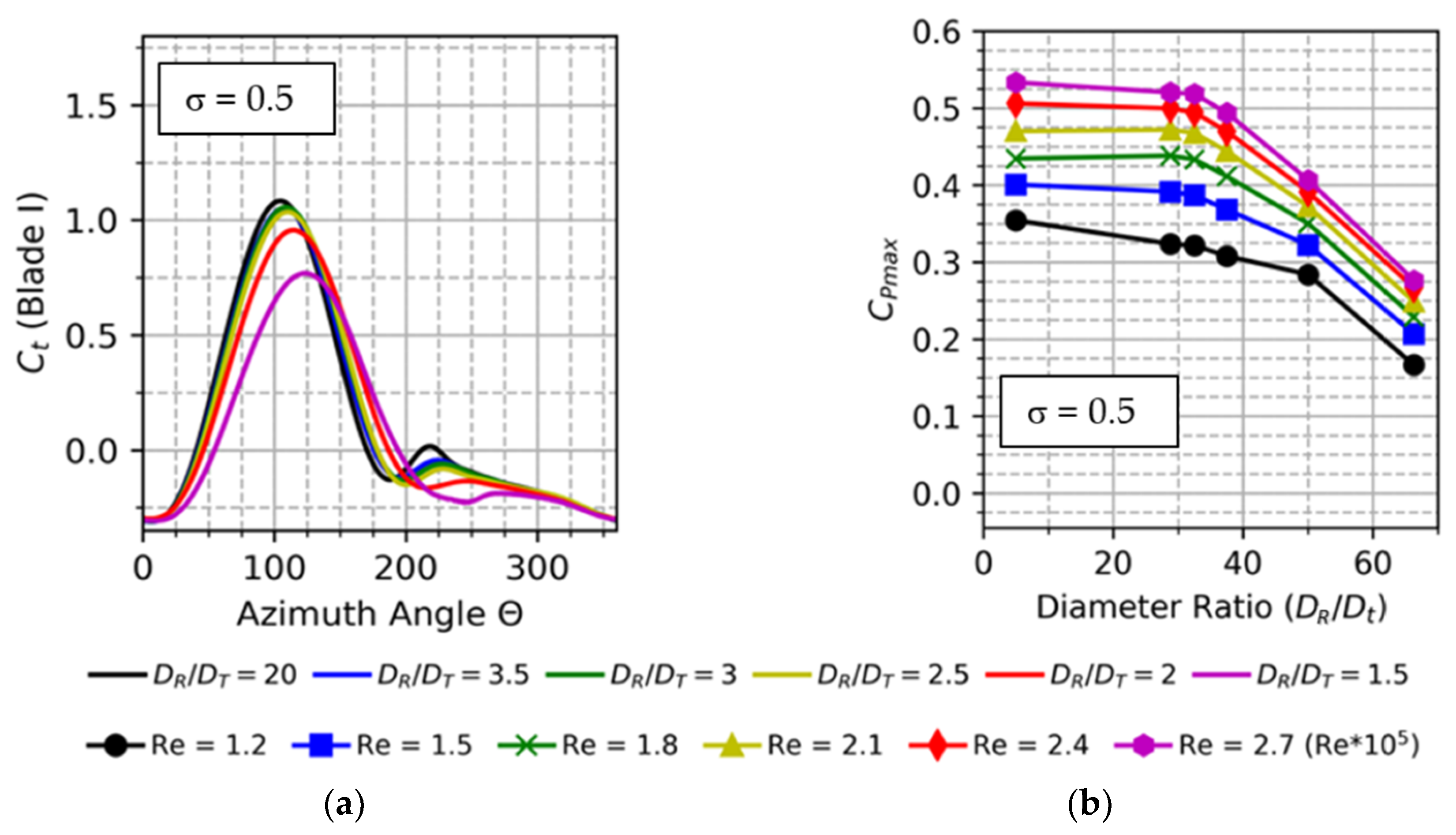
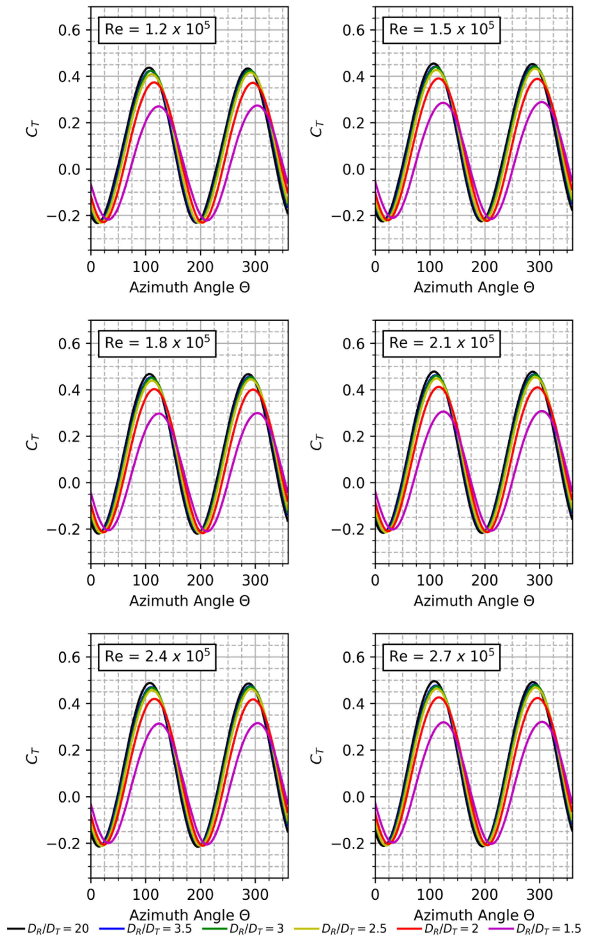
The operating TSR range (λ) considered in the present work is 1 to 4 for the two-bladed rotor at an increment of 0.2. Computing at a TSR, below the mentioned range, is of no significance for this optimization study, and above the indicated range means operating beyond stall conditions. For high solidities, power and efficiency rapidly decrease at stall conditions. The free stream wind speed for which the AHDT configurations are simulated is between 4 m/s and 9 m/s which is converted to Re for further descriptions in this study. The instantaneous torque coefficient (Ct) versus azimuth angle () is computed for a range of Re = 1.2 × 10⁵ to Re = 2.7 × 10⁵. The results for the single blade are plotted in Figure 5a. For each Re, the various DR/DT ratios are evaluated for one complete revolution (0° to 360°). It shows that as DR/DT ratio increases, the peak torque coefficient in the Ct cycle increases. The torque coefficient for the rotor at different Re and different DR/DT is displayed in Figure 6. It can be seen that the two peak torque coefficients constantly decrease as the diameter of the cylinder increases. Also, it is evident that as the diameter of the cylinder increases, the azimuthal angle at peak Ct shifts. This can be attributed to the change in the relative wind velocity due to vortices from the cylinder.
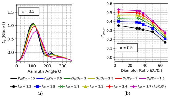
Figure 5.
(a) Torque coefficient of single blade; (b) Cpmax for different diametrical ratio.
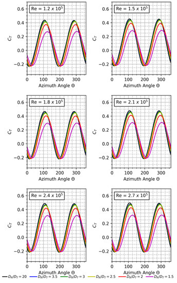
Figure 6.
Effect of Re on Torque Coefficient.
7.2. Power Coefficient Comparison for Different (DR/DT)
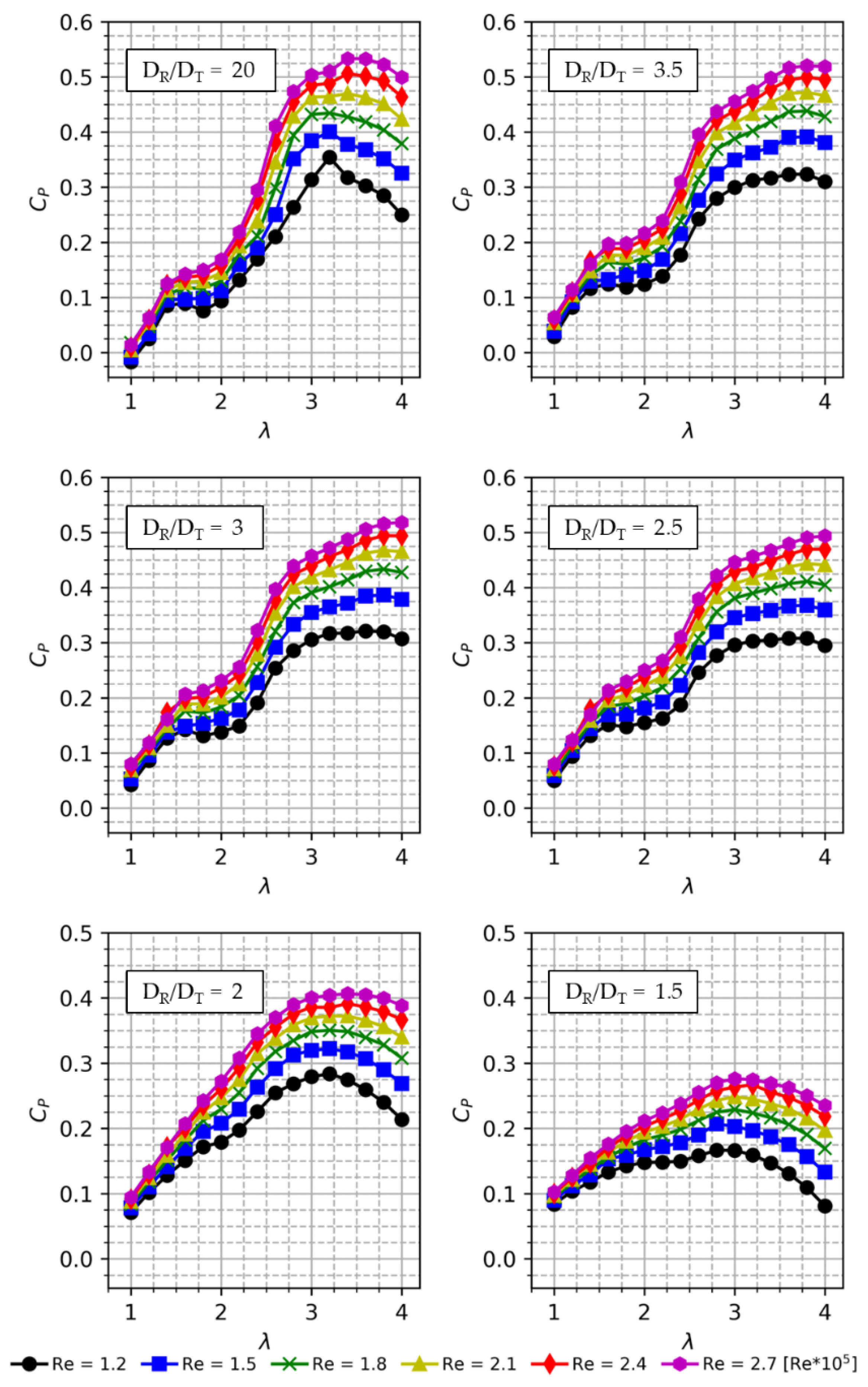
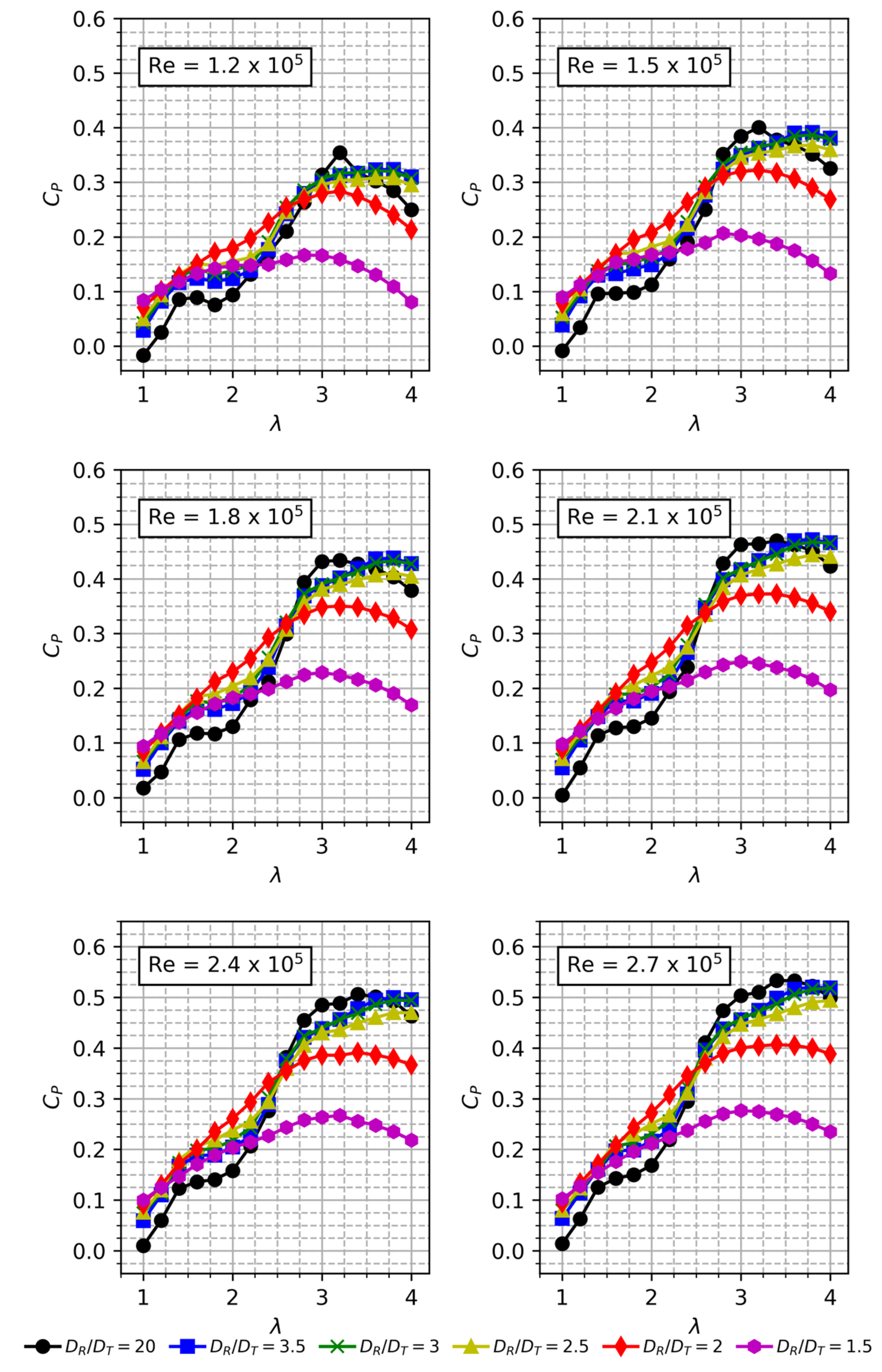
Figure 7 shows the power curves of the AHDT for the two-bladed rotors corresponding to the solidity of = 0.5. Each subplot in Figure 7 shows the power curve (Cp vs. λ) for their respective diameter ratio (DR/DT). The power curves are calculated for a range of Re = 1.2 × 10⁵ to Re = 2.7 × 10⁵. Figure 5b shows the comparison of the maximum power coefficient (Cpmax) with the investigated Re and DR/DT ratio. As mentioned before, the DR/DT = 20 corresponds to the conventional Darrieus rotor. Figure 8 shows the Cp curve at different Re ranging from Re = 1.2 × 10⁵ to Re = 2.7 × 10⁵. It can be seen from Figure 8 that for the low Re of 1.2, 1.5 and 1.8 × 10⁵, the optimal TSR is 3.2.
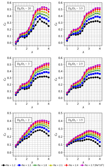
Figure 7.
Cp vs Tip Speed Ratio (TSR) for different DR/DT.
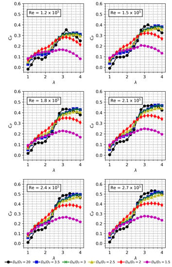
Figure 8.
Cp vs TSR for different Re.
However, for a higher Re of 2.1, 2.4 and 2.7 × 10⁵, the optimal TSR shifts to 3.4. The maximum power coefficient increases by 11.7% at Re = 1.5 × 10⁵ when compared to Re = 1.2 × 10⁵. At Re = 1.8, 2.1 and 2.4 × 10⁵, the percentage increase in Cpmax is 18.4%, 24.6% and 30% higher than the Cpmax at Re = 1.2 × 10⁵. At Re = 2.7 × 10⁵, the Cpmax value is 0.533 which is 33.6% higher than the Cpmax obtained at the low Re of 1.2 × 10⁵. For the diameter ratio up to DR/DT = 2.5, the Cp curves show a dip before reaching the maximum Cp, except for the DR/DT = 20. By poring over the data, it is evident that the power loss occurs at TSR ~2. The loss in power reflecting as the dip is attributed to the vortices from the cylinder interacting with the Darrieus blades. The frequency of the vortices can be deduced from Strouhal number ( as given by Equation (10),
where fs is the vortex-shedding frequency, D is the across-wind dimension of the body, and V is the mean velocity of the uniform flow. The frequency of the vortices and the blade passing frequency are correlated at TSR 2, resulting in power loss. The Cp curve of the larger diameter cylinder does not exhibit this kind of power loss, as the cylinder acts as a bluff body generating a large wake, where the wake width occupies most of the downstream path. For DR/DT = 1.5, the maximum Cp achieved for the Re = 2.7 × 10⁵ is 0.27, whereas for the same Re, DR/DT = 20, the peak Cp is 0.53 (Table 1). It is evident that the diametrical ratio of 1.5 and 2 significantly reduce the power coefficient by more than half. Hence, these diameters are not suitable for AHDT. Another interesting finding is that the maximum Cp is a sharp curve for the lower diameter ratio, and as the cylinder diameter increases, the maximum Cp although it is low, is maintained over a wider TSR, making the curve flat rather than sharp. The advantage is that a higher power can be extracted from the turbine for a wide wind speed range.

Table 1.
Difference in Cp at various Re.
The difference in the Cp values for a low Re of 1.2 × 10⁵ is comparatively lower than the difference in Cp for the higher Re of 2.7 × 10⁵ for different diameter ratios. At lower Re, the Darrieus rotor by itself has a lower Cp value and the impact of turbulent flow from the cylinder is comparatively low. The peak Cp value for Re 1.2 × 10⁵ stays at 0.3 for all the investigated diameters. As the diametrical ratio increases to 1.5, the Cp curve stays at 0.1 for all the TSR. It can be concluded from the Cp curves comparison for various DR/DT that the DR/DT = 2.5, 2 and 1.5 reduces the Cp by more than half, hence these diameters are not suitable for AHDT further optimization.
7.3. Effect of Re on Cp for Different DR/DT
Re is a critical factor in determining the power production capability and starting behaviour of a Darrieus rotor. For a conventional Darrieus rotor, the starting torque entirely rests on the lift generated at low Re, but for AHDT, the starting torque is generated by drag rather than lift. Hence, the study on the influence of Re aims to shed light on the power performance of AHDT and flow over cylinder rather than the starting behaviour of AHDT at low Re. By comparing different diametrical ratios for the given Re, i.e. wind speed, a suitable cylinder diameter or in other words, the diameter of the Savonius buckets, can be determined.
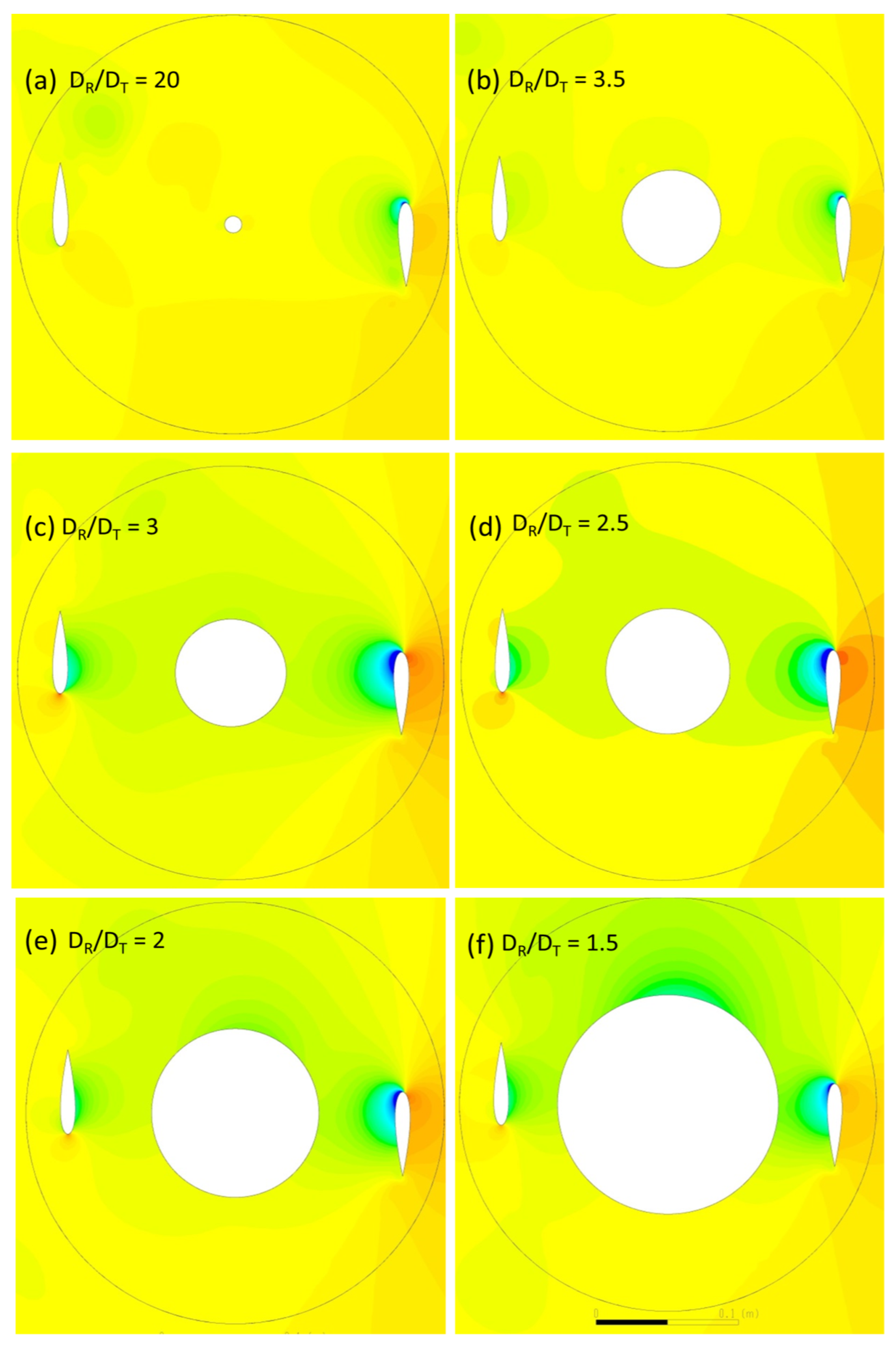
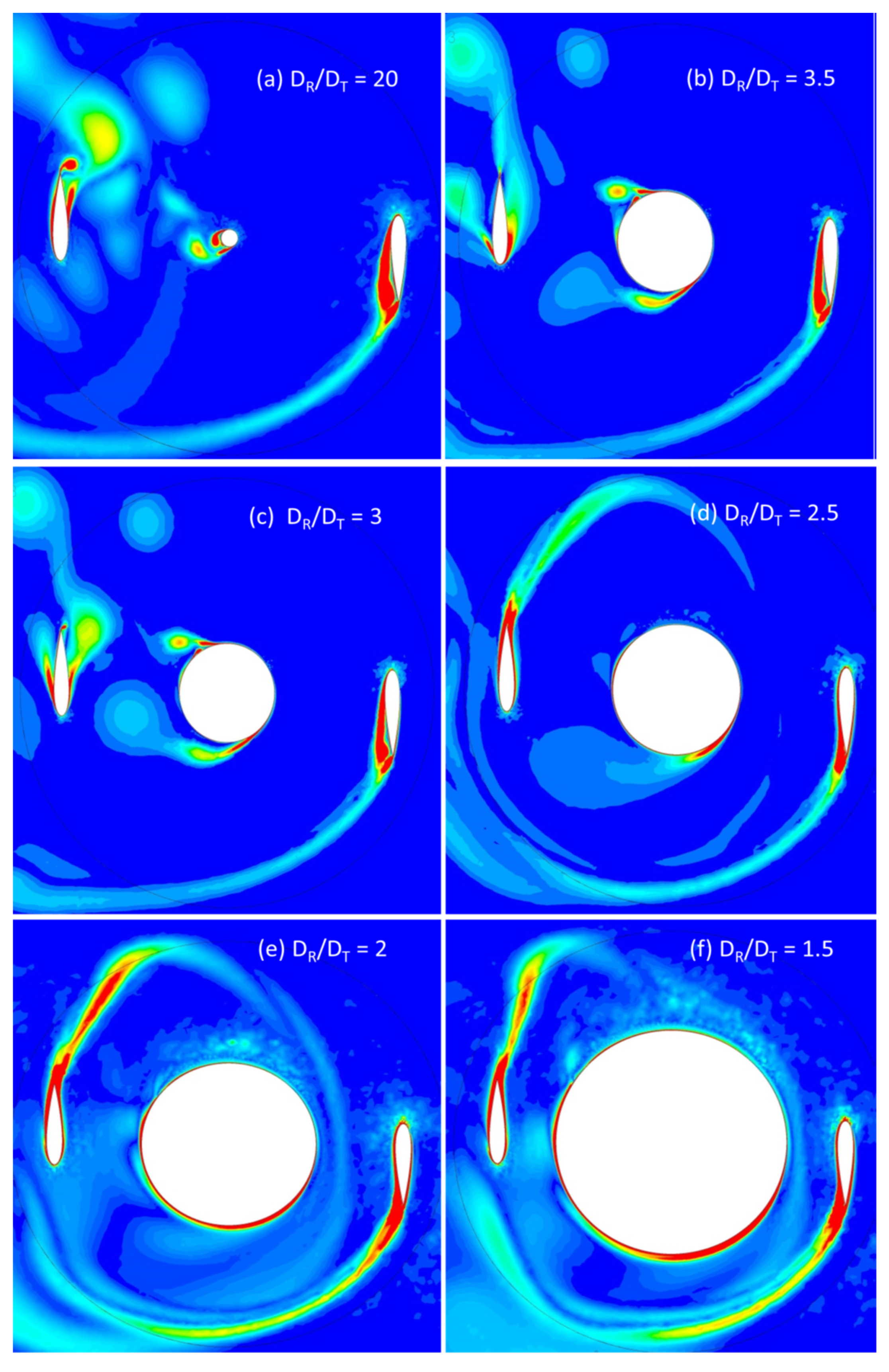
It is not always pertinent to choose a smaller diameter cylinder to maximize the Cp of Darrieus rotor, as the vortices of the cylinder at a given Re can deteriorate the torque of Darrieus blades more than larger diameter cylinder. Hence, it is imperative to perform the simulation iteratively for DR/DT = 20 to DR/DT =1.5. The results are critical from the structural perspective, as a loss in Cp will indicate a vortex shedding and further instigate to optimize the aspect ratio of the cylinder. Based on the Re regime, the flow over the cylinder may differ at large. The pressure gradient on the cylinder and the boundary layer may give rise to vortices of different diameters. The boundary layer upstream of the cylinder must overcome a strong pressure gradient set up by the cylinder. This leads to separation of the flow, and in the separated region, a vortex system is developed which is stretched around the cylinder like a horseshoe. Hence, AHDT behaviour at higher Re = 2.1 × 10⁵ is of particular interest. The Cp curves for the investigated Re are shown in Figure 8. For all the diametrical ratios, except DR/DT = 1.5, the Cp curves are almost similar. The Cp values increase steadily as the Re increases. For 2.4 × 10⁵, the peak Cp achieved is 0.3 for all the diametrical ratios except 1.5, for which the Cp is 0.2, due to wake expansion as seen from Figure 9. Vorticity contours corresponding to the DR/DT = 1.5 reveal that the Darrieus blades are operating in the large wake generated by the cylinder as shown in Figure 10.
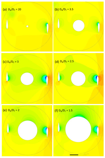
Figure 9.
Pressure contours (Pa) for AHDT at β = 0°.
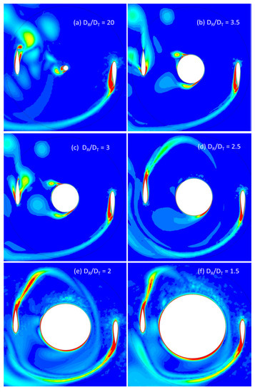
Figure 10.
Vorticity contours (S−1) for AHDT at β = 0°.
7.4. Discussion of Pressure and Vorticity Contours
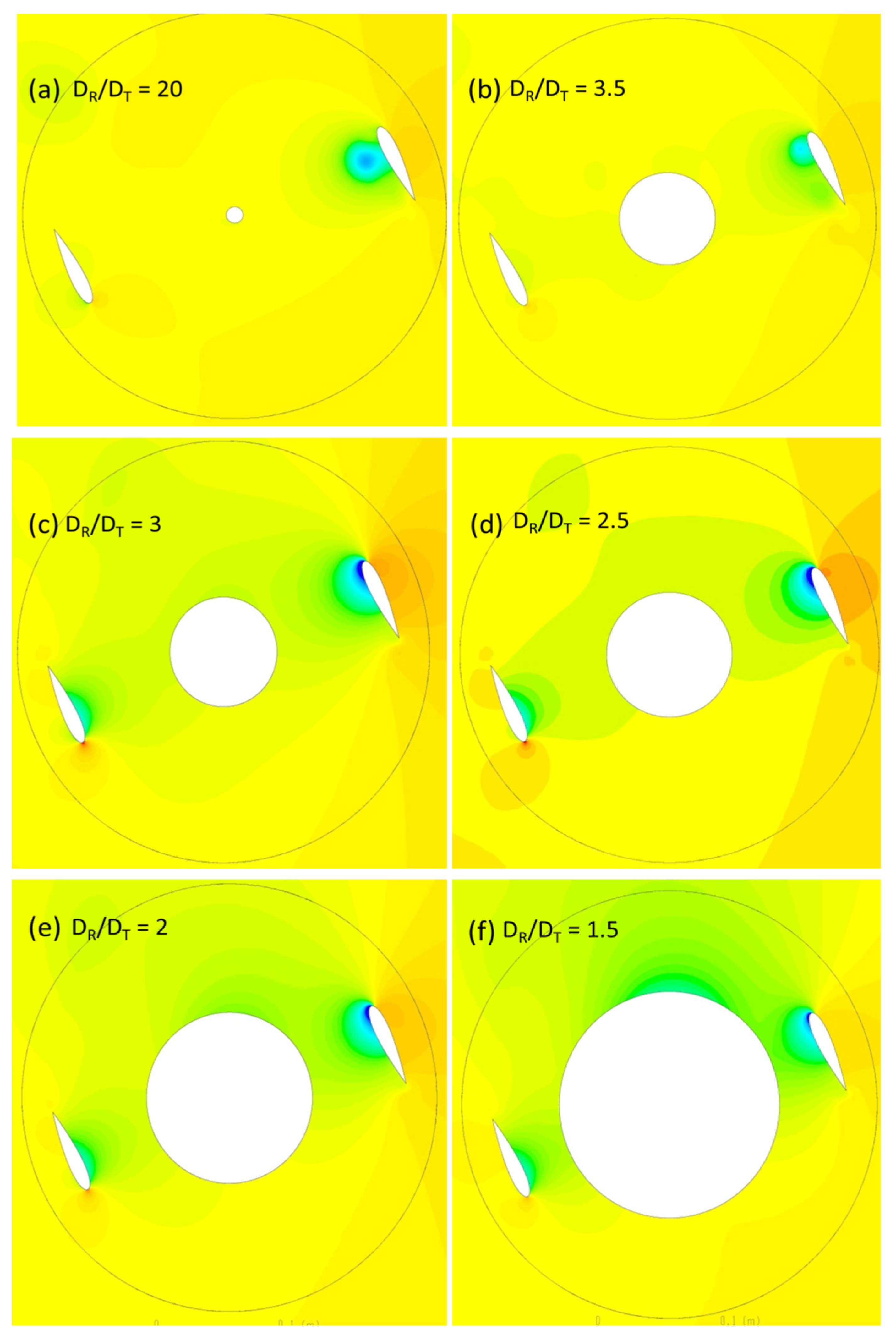
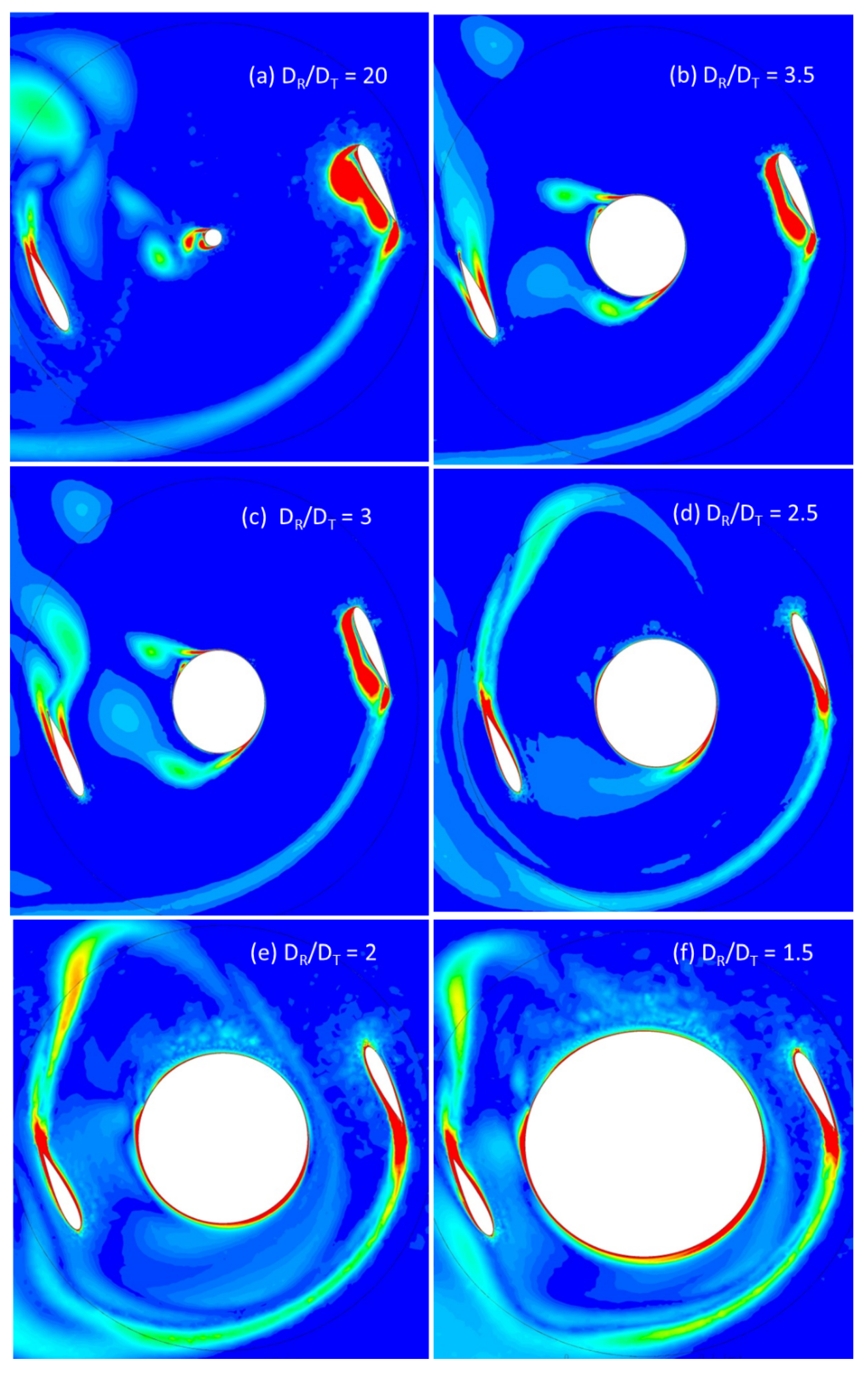
The pressure contours for different diametrical ratios are compared in Figure 11 and Figure 12 for azimuthal position 0° and 30° respectively. The azimuthal angle is of particular interest to analyze in detail, as the wake from the Darrieus blades and the Savonius buckets in closed conditions (cylinder) will be maximum, resulting in a higher power loss. For the rest of the azimuthal angles, the wake from the Darrieus blades are dispersed before it reaches the Savonius buckets. For the ratio DR/DT = 20, the flow pattern in the rotor is similar to a conventional Darrieus rotor, as the cylinder resembles the center shaft of the conventional turbine. For some of the cantilevered tower designs, the centre shaft diameters will be even higher than the diametrical ratio of 20. The wake pattern observed is similar to the Darrieus rotor, with low pressure behind the Darrieus blades with a peak power coefficient of 0.35. For DR/DT = 3.5, the cylinder wake starts to appear with a low-pressure zone downstream. The corresponding vorticity for the azimuthal angle β = 0° indicates that the flow on the cylinder starts to separate with alternate vortices on both sides. The vortices are small and smoothly travel downstream, eventually regaining the freestream velocity. At β = 30°, a similar pressure drop occurs without any noticeable difference between two angles. For the ratio DR/DT = 3, the cylinder diameter is comparatively larger, and the pressure drops around the cylinder is noticeable.
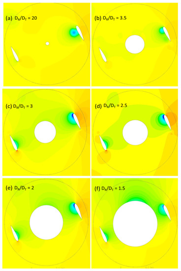
Figure 11.
Pressure contours (Pa) for AHDT at β = 30°.
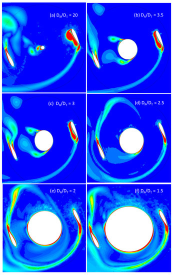
Figure 12.
Vorticity contours (S−1) for AHDT at β = 30°.
The wake arising due to the pressure difference from the Darrieus blades progressively extends to the center cylinder, forming a large low-pressure zone. Though the intensity is not high, the low-pressure zone influences the power loss, decreasing the peak power coefficient as evident from Figure 7. For the ratio DR/DT = 2.5, the cylinder influence on the power coefficient of the Darrieus rotor is well pronounced. From the pressure contours on Figure 11d, the low-pressure zone extends from the upstream Darrieus blades through the cylinder to the downstream blades. The significant loss in power can be attributed to the size of the vortices compared to the blade chord and the downstream path where it encounters the blades. TSR plays a crucial role in generating asymmetric alternating wake. Von Karman vortices are formed due to flow separation from the cylinder. Up to this diametrical ratio, the wake can be clearly distinguished between the Darrieus blades and the cylinder wake. As the cylinder diameter increases further to the ratio of DR/DT = 2, the whole rotor is in the wake, which is evident from the pressure contour as shown in Figure 11e,f. An interesting finding is that the flow starts to deflect before it reaches the cylinder, disturbing the flow upstream on the Darrieus rotor. Due to the low speed and high energy turbulent flow, the Darrieus blades also leave a large wake behind. As evident from the corresponding Cp graph, the power loss is significantly low as power generation happens only at limited azimuthal angles and the energy has to be expended for the majority of the downstream travel path. The same flow pattern repeats for other azimuthal positions. The von Karman vortices are unstable and break down due to Strouhal instability.
8. Conclusions
2D steady-state simulations are performed on the proposed AHDT in an effort to determine the optimum Savonius diameter that can be integrated with the Darrieus rotor to maximize its performance for the complete operating range. Turbulence is modelled with the k-ω SST equation. As the flow pattern over the cylinder will be sub critical or critical based on the Re, the study systematically investigates their performance on Darrieus rotor with a fixed diameter. The power loss of the Darrieus rotor is more than half for the cylinder diameter ratio (DR/DT) of 2 and 1.5, as power has to be expended for the blades when it passes through downstream. A smaller (DR/DT) leads to a smaller Savonius bucket diameter which reduces the turbine performance in the low wind speeds. Hence, it can be concluded that DR/DT should lie around 3 to maximize the Darrieus turbine performance for the whole of the wind speed spectrum. The optimum diameter can be concluded after evaluating the performance of the high solidity three-bladed turbine and the starting capability when the Savonius rotor is in open condition. The starting performance of AHDT with open Savonius will be investigated in part 2, extending the current study. The investigation of the performance of AHDT with various airfoil profiles, solidity, and aspect ratios can be intriguing for future research.
Author Contributions
Funding acquisition, S.R. and H.W.; Project administration, H.W.; Supervision, T.-C.L.; Writing—original draft, P.M.K. and M.R.S.; Writing—review & editing, K.S.
Funding
This research was funded by 2016 ASTAR AME IRG Grant.
Conflicts of Interest
The authors declare no conflict of interest.
References
- International Energy Agency. Available online: https://www.iea.org/ (accessed on 4 April 2019).
- Karthikeya, B.; Negi, P.S.; Srikanth, N. Wind resource assessment for urban renewable energy application in Singapore. Renew. Energy 2016, 87, 403–414. [Google Scholar] [CrossRef]
- Shikha; Bhatti, T.S.; Kothari, D.P. Early Development of Modern Vertical and Horizontal Axis Wind Turbines: A Review. Wind Eng. 2005, 29, 287–299. [Google Scholar] [CrossRef]
- IEC 61400-2:2013 Wind Turbines Part 2: Small Wind Turbines. Available online: https://webstore.iec.ch/publication/5433 (accessed on 17 May 2019).
- Golecha, K.; Kamoji, M.A.; Kedare, S.B.; Prabhu, S.V. Review on Savonius Rotor for Harnessing Wind Energy. Wind Eng. 2012, 36, 605–645. [Google Scholar] [CrossRef]
- Mohan Kumar, P.; Surya, M.M.R.; Narasimalu, S.; Lim, T.-C. Experimental and numerical investigation of novel Savonius wind turbine. Wind Eng. 2019, 43, 247–262. [Google Scholar] [CrossRef]
- Kumar, P.M.; Purimitla, S.R.; Shubhra, S.; Srikanth, N. Numerical and analytical study on telescopic savonius turbine blade. In Proceedings of the 2017 3rd International Conference on Power Generation Systems and Renewable Energy Technologies (PGSRET), Johor Bahru, Malaysia, 4–6 April 2017; IEEE: Piscataway, NJ, USA, 2017; pp. 107–112. [Google Scholar]
- Gorlov, A. Development of the Helical Reaction Hydraulic Turbine; Final Technical Report; Northeastern Univ.: Boston, MA, USA, 1998. [Google Scholar]
- Baker, J. Features to aid or enable self starting of fixed pitch low solidity vertical axis wind turbines. J. Wind Eng. Ind. Aerodyn. 1983, 15, 369–380. [Google Scholar] [CrossRef]
- Shiono, M.; Suzuki, K.; Kiho, S. Output characteristics of Darrieus water turbine with helical blades for tidal current generations. In Proceedings of the Twelfth International Offshore and Polar Engineering Conference, Kitakyushu, Japan, 26–31 May 2002; ISOPE: Cupertino, CA, USA, 2002. [Google Scholar]
- Kumar, M.; Surya, M.M.R.; Sin, N.P.; Srikanth, N. Design and experimental investigation of airfoil for extruded blades. Int. J. Adv. Agric. Environ. Eng. 2017, 3, 359–400. [Google Scholar]
- Kumar, P.M.; Surya, M.M.R.; Kethala, R.; Srikanth, N. Experimental investigation of the performance of darrieus wind turbine with trapped vortex airfoil. In Proceedings of the 2017 3rd International Conference on Power Generation Systems and Renewable Energy Technologies (PGSRET), Johor Bahru, Malaysia, 4–6 April 2017; IEEE: Piscataway, NJ, USA, 2017; pp. 130–135. [Google Scholar]
- Kumar, P.M.; Surya, M.M.R.; Srikanth, N. On the improvement of starting torque of darrieus wind turbine with trapped vortex airfoil. In Proceedings of the 2017 IEEE International Conference on Smart Grid and Smart Cities (ICSGSC), Singapore, 23–26 July 2017; IEEE: Piscataway, NJ, USA, 2017; pp. 120–125. [Google Scholar]
- Kumar, P.M.; Ajit, K.R.; Surya, M.R.; Srikanth, N.; Lim, T.-C. On the self starting of darrieus turbine: An experimental investigation with secondary rotor. In Proceedings of the 2017 Asian Conference on Energy, Power and Transportation Electrification (ACEPT), Singapore, 24–26 October 2017; IEEE: Piscataway, NJ, USA, 2017; pp. 1–7. [Google Scholar]
- Kumar, P.M.; Kulkarni, R.; Srikanth, N.; Lim, T.-C. Performance Assessment of Darrieus Turbine with Modified Trailing Edge Airfoil for Low Wind Speeds. Smart Grid Renew. Energy 2017, 8, 425–439. [Google Scholar] [CrossRef]
- Wakui, T.; Tanzawa, Y.; Hashizume, T.; Nagao, T. Hybrid configuration of Darrieus and Savonius rotors for stand-alone wind turbine-generator systems. Electr. Eng. Jpn. 2005, 150, 13–22. [Google Scholar] [CrossRef]
- Kjellin, J.; Bernhoff, H. Electrical starter system for an H-rotor type VAWT with PM-generator and auxiliary winding. Wind Eng. 2011, 35, 85–92. [Google Scholar] [CrossRef]
- Chougule, P.D.; Nielsen, S.R.K.; Basu, B. Active Blade Pitch Control for Straight Bladed Darrieus Vertical Axis Wind Turbine of New Design. Key Eng. Mater. 2013, 569–570, 668–675. [Google Scholar] [CrossRef]
- Hwang, I.S.; Min, S.Y.; Jeong, I.O.; Lee, Y.H.; Kim, S.J. Efficiency improvement of a new vertical axis wind turbine by individual active control of blade motion. In Proceedings of the SPIE Smart Structures and Materials + Nondestructive Evaluation and Health Monitoring, San Diego, CA, USA, 5 April 2006; SPIE: Bellingham, WA, USA; p. 617311. [Google Scholar]
- Rassoulinejad-Mousavi, S.; Jamil, M.; Layeghi, M. Experimental study of a combined three bucket H-rotor with savonius wind turbine. World Appl. Sci. J. 2013, 28, 205–211. [Google Scholar]
- Gupta, R.; Das, R.; Sharma, K. Experimental study of a Savonius-Darrieus wind machine. In Proceedings of the International Conference on Renewable Energy for Developing Countries, Washington, DC, USA, 6 April 2006. [Google Scholar]
- Gupta, R.; Sharma, K. Flow physics of a combined Darrieus-Savonius rotor using computational fluid dynamics (CFD). Int. Res. J. Eng. Sci. Technol. Innov. 2012, 1, 1–13. [Google Scholar]
- Kyozuka, Y. An experimental study on the Darrieus-Savonius turbine for the tidal current power generation. J. Fluid Sci. Technol. 2008, 3, 439–449. [Google Scholar] [CrossRef]
- Tescione, G.; Ragni, D.; He, C.; Ferreira, C.S.; Van Bussel, G. Near wake flow analysis of a vertical axis wind turbine by stereoscopic particle image velocimetry. Renew. Energy 2014, 70, 47–61. [Google Scholar] [CrossRef]
- Balduzzi, F.; Drofelnik, J.; Bianchini, A.; Ferrara, G.; Ferrari, L.; Campobasso, M.S. Darrieus wind turbine blade unsteady aerodynamics: a three-dimensional Navier-Stokes CFD assessment. Energy 2017, 128, 550–563. [Google Scholar] [CrossRef]
- Ferreira, C.S.; Van Kuik, G.; Van Bussel, G.; Scarano, F. Visualization by PIV of dynamic stall on a vertical axis wind turbine. Exp. Fluids 2009, 46, 97–108. [Google Scholar] [CrossRef]
- Balduzzi, F.; Bianchini, A.; Maleci, R.; Ferrara, G.; Ferrari, L. Blade design criteria to compensate the flow curvature effects in H-Darrieus wind turbines. J. Turbomach. 2015, 137, 011006. [Google Scholar] [CrossRef]
- Rezaeiha, A.; Kalkman, I.; Blocken, B. Effect of pitch angle on power performance and aerodynamics of a vertical axis wind turbine. Appl. Energy 2017, 197, 132–150. [Google Scholar] [CrossRef]
- Kumar, P.M.; Surya, M.M.R.; Srikanth, N. Comparitive CFD analysis of darrieus wind turbine with NTU-20-V and NACA0018 airfoils. In Proceedings of the 2017 IEEE International Conference on Smart Grid and Smart Cities (ICSGSC), Singapore, 23–26 July 2017; IEEE: Piscataway, NJ, USA, 2017; pp. 108–114. [Google Scholar]
- Rezaeiha, A.; Kalkman, I.; Montazeri, H.; Blocken, B. Effect of the shaft on the aerodynamic performance of urban vertical axis wind turbines. Energy Convers. Manag. 2017, 149, 616–630. [Google Scholar] [CrossRef]
- Fujisawa, N.; Gotoh, F. Visualization study of the flow in and around a Savonius rotor. Exp. Fluids 1992, 12, 407–412. [Google Scholar] [CrossRef]
- Kumar, P.M.; Rashmitha, S.R.; Srikanth, N.; Lim, T.-C. Wind Tunnel Validation of Double Multiple Streamtube Model for Vertical Axis Wind Turbine. Smart Grid Renew.Energy 2017, 8, 412–424. [Google Scholar] [CrossRef][Green Version]
- Kumar, P.M.; Ajit, K.R.; Srikanth, N.; Lim, T.-C. On the Mathematical Modelling of Adaptive Darrieus Wind Turbine. J. Power Energy Eng. 2017, 5, 133–158. [Google Scholar] [CrossRef][Green Version]
- Kumar, P.M.; Anbazhagan, S.; Srikanth, N.; Lim, T.-C. Optimization, Design, and Construction of Field Test Prototypes of Adaptive Hybrid Darrieus Turbine. J. Fundam. Renew. Energy Appl. 2017, 7, 245. [Google Scholar]
- Rezaeiha, A.; Kalkman, I.; Blocken, B. CFD simulation of a vertical axis wind turbine operating at a moderate tip speed ratio: guidelines for minimum domain size and azimuthal increment. Renew. Energy 2017, 107, 373–385. [Google Scholar] [CrossRef]
© 2019 by the authors. Licensee MDPI, Basel, Switzerland. This article is an open access article distributed under the terms and conditions of the Creative Commons Attribution (CC BY) license (http://creativecommons.org/licenses/by/4.0/).

