Article

Identification of the Structures for Low Reynolds Number Flow in the Strong Magnetic Field

by
Łukasz Pleskacz
and
Elzbieta Fornalik-Wajs
*
AGH University of Science and Technology, Department of Fundamental Research in Energy Engineering, Al. Mickiewicza 30, 30-059 Krakow; Poland
*
Author to whom correspondence should be addressed.
Fluids 2019, 4(1), 36; https://doi.org/10.3390/fluids4010036
Submission received: 10 January 2019 / Revised: 10 February 2019 / Accepted: 18 February 2019 / Published: 25 February 2019
(This article belongs to the Special Issue Numerical Analysis of Magnetohydrodynamic Flows)

Abstract

:
Thermomagnetic convection is still a phenomenon which generates interest among researchers. The authors decided to focus their attention on the magnetic field influence on forced convection and analyze the extended Graetz–Brinkman problem. A numerical model based on a commonly available solver implemented with user-defined functions was used. The results exhibited the variety of possible flow structures depending on the dimensionless parameters, namely Prandtl and Reynolds numbers. Three flow structure classes were distinguished, and they provide a platform for further research.

1. Introduction

The ability of a magnetic field to affect all kinds of substances (reported by Michael Faraday in 1847) has been considered more and more useful in recent years. Apart from large-scale projects like Hyperloop or studying well-developed branches of science, such as ferrohydrodynamics (FHD) or biohydrodynamics (BFD), there is also a direction of research that is escaping so-called ‘common sense’. Thermomagnetic convection refers to the phenomenon concerning the behavior of weakly magnetic fluids (i.e., air) in the presence of a strong magnetic field but being a part of magnetohydrodynamics (MHD). This small magnetism should not be underestimated. The magnetic force is a body force much like the gravitational one, and therefore, utilization of this small magnetism might be of great value for thermal devices working in zero gravity conditions.
The most important turn, paving a path for further research, was the discovery of high-temperature superconductivity in 1986 by Bednorz and Muller [1]. This discovery was awarded the Nobel Prize in Physics and led to the construction of superconducting magnets. Soon after that, Braithwaite et al. [2] reported that a magnetic field is able to enhance heat transfer during natural convection of a weakly-magnetic fluid. Subsequent years saw numerous new experimental reports [3,4,5]. As for the early numerical studies, two papers should be mentioned. They were both elaborated on by Tagawa et al. and concerned the behavior of air [6] and water [7] in cubical and cylindrical cavities. They were followed by the analysis of other paramagnetic fluids [8,9].
In recent years, the number of papers has gradually increased, indicating both an interest in and the potential of this branch of science. One promising aspect is the combination of the abovementioned abilities and nanofluid properties [10], which might lead to heat transfer modifications. The cavities of various shapes and aspect ratios have also been taken into consideration [11,12,13]. From a medical point of view, it is worth mentioning magnetic drug delivery, i.e., aerosols, in the human respiratory system [14].
The authors approached the problem from a different angle, proposed by Ozoe [15], and presented a set of papers concerning magnetic force influence on the forced convection phenomenon. The published reports referred to four systems: The flow in the circular duct [16], a duct with a simplified stenosis [17], a duct with an elbow [18], and heat transfer modification [19].
The aim of these analyses stemmed from the fact that in the case of heterogeneous fluids, flow through the channels of various shapes might lead to the exceptionally unwanted phenomenon of sedimentation in the form of agglomerates. These agglomerates handicap the flow and have a negative impact, both on hydrodynamic and thermal parameters. The occurrence of this phenomenon causes pressure loss and a decrease of volumetric flow rate and makes heat transfer less intensive. Today, the methods used to eliminate these sediments are invasive, and therefore, their usage influences the overall process occurring in a given system. At worst, it leads to temporary shutting down of a system for the duration of the cleaning process. In the case of most primitive methods used in households, it is connected with the necessity of the system’s dismantling and clearance in a mechanical way. The great majority of sediments are substances of weakly-magnetic properties (belonging to the group of para- and diamagnetics). To date, the authors have studied single-phase weakly-magnetic fluids to understand comprehensively the extent of magnetic field impact on forced convection. By contrast, the long-term purpose of the present research is to estimate magnetic field ability for non-invasive clearage of sediments in the ducts of complicated geometry during the flow of weakly-magnetic liquids.
In this paper, the low Reynolds number flow of a single-phase in a strong magnetic field numerical study is presented for a wide range of Prandtl number values. The flows of low Reynolds number values occur widely in industrial applications. Fluids such as tars, oils, or honeys are taken into account. Many of these substances are paramagnetics. The aim of the calculations in such a range of Prandtl number values was to understand the influence of magnetic field on various fluids under analyzed conditions. However, the obtained Reynolds number values (Re = 1 and Re = 10) do not allow treating the studied flows as Stokes flows. The analyses resulted in a wide range of various flow structure types, offering enhanced understanding of the transport phenomena.

2. Model and Methods

In this section, the mathematical model and the studied case are discussed.

2.1. Constitutive Modeling

The mass conservation equation took the form [20]:
· u = 0
where u—velocity (m/s), for the following assumptions:
  • Stationary flow;
  • Three-dimensional flow;
  • Incompressible flow;
  • Lack of additional mass sources.
The momentum conservation equation was described by the equation [20]:
ρ ( u · u ) = p + μ 2 u + F b
where ρ —density (kg/m3), p —pressure (Pa), μ —dynamic viscosity (Pa·s), F b = F g + F mag —body forces (N/m3), F g —gravitational force (N/m3), and F mag —magnetic force (N/m3). The momentum conservation equation was formulated with the following additional assumptions:
  • Laminar flow;
  • Gravitational and magnetic forces were treated as the body forces;
  • Gravitational buoyancy force was formulated with the usage of the Boussinesq approximation.
The next equation is a formulation of the utilized energy conservation equation [20]:
u · T = a 2 T
where T —temperature (K) and a —thermal diffusivity (m2/s). It was based on the assumptions:
  • No species diffusion in the system;
  • Radiation effects were ignored;
  • Viscous dissipation was negligible (Brinkman number Br ≪ 1, Equation (8));
  • Lack of additional energy sources (including magnetic, which can be and was considered negligible).
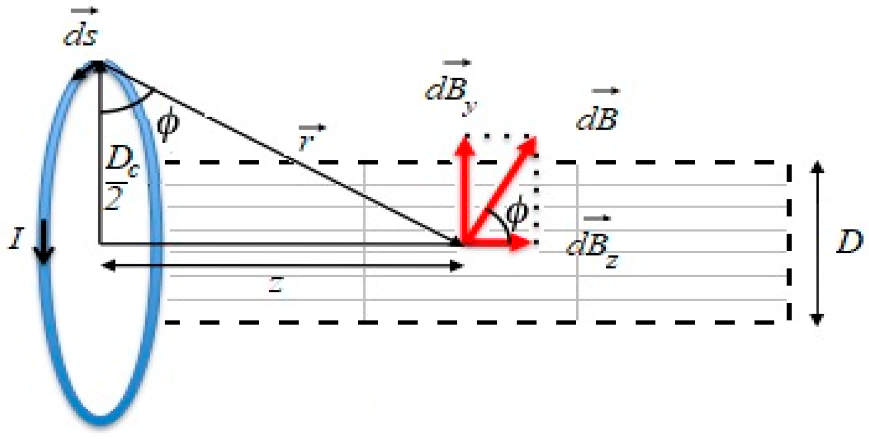
In order to calculate the magnetic force, Biot–Savart’s law was utilized [21]:
B = μ m i 4 π c d s × r | r | 3
where B —magnetic induction (T), μ m —magnetic permeability (H/m), i —electrical current (A), d s —infinitely small element of the coil (m), and r —position vector (m). The following assumptions were used in the above-stated formulation of Biot–Savart’s law:
  • Single, circular coil;
  • Infinitely thin conductor.
Finally, the magnetic force was calculated as follows [6]:
F mag = ( 1 + 1 T 0 β ) χ m ρ ( T T 0 ) 2 μ m B 2
where T 0 —reference temperature (K), T —local fluid temperature (K), β —thermal expansion coefficient (K−1), and χ m —mass magnetic susceptibility (m3/kg).
The Reynolds number is defined as follows:
Re = u ρ D μ
where u —average flow velocity (m/s) and D —pipe diameter (m).
The following formula describes the Prandtl number:
Pr = c μ λ
where c —specific heat (J/(kg·K)) and λ —thermal conductivity (W/m·K).
The Brinkman number is defined by the formula:
Br = μ u 2 λ ( T w T b )
where T w —wall temperature (K) and T b —bulk temperature (K).
The vorticity is calculated as follows:
ω = × u
The normalized local velocity is defined in the following way:
u n = u u i
where u —local velocity (m/s) and u i —initial maximum flow velocity.

2.2. The Studied Case

The studied case is the extended Graetz–Brinkman problem. The considered system is a three-dimensional circular duct (pipe), the wall of which is divided in two parts: Adiabatic and isothermally heated. The magnetic coil is located at the border between these two parts. Its diameter is equal to double the diameter of the pipe. The flow is assumed to be fully developed and laminar at the inlet, and the environmental pressure is assumed at the outlet. The studied system is shown in Figure 1.
The magnetic induction in the center of the studied system was equal to 5 T and 10 T, respectively, and the temperature difference between the inlet cold fluid and the heated wall was 10 K. The Reynolds number was 1 or 10. The working fluid used for computations was gadolinium nitrate hexahydrate (80% mass glycerol aqueous solution) [8]. The working fluid properties are listed in Table 1. The Prandtl number value modifications were performed with a change in the specific heat value.
The unstructured grid was constructed with around 180,000 wedge shaped elements. The numerical computations were performed with the usage of ANSYS Fluent software (ACK Cyfronet AGH, Krakow, Poland), which was supplemented with the dedicated user-defined functions. The set of first order upwind schemes was used to solve the conservation equations.

2.3. The Computation of the Magnetic Induction Distribution

Figure 2 schematically describes the approach to the computation of Biot–Savart’s law. The circular coil of infinitely small thickness was divided into 1440 elements. The electric current direction was considered counter-clockwise. Each of the magnetic induction components was computed with the usage of the code written in C programming language (required by the utilized solver) and the solver’s built-in macros. The following steps were taken:
  • Computation of the coil geometry and coil elements matrix;
  • Computation of the position vectors matrix;
  • Computation of the magnetic induction components based on the vector products of the abovementioned quantities with the usage of solver built-in loops.
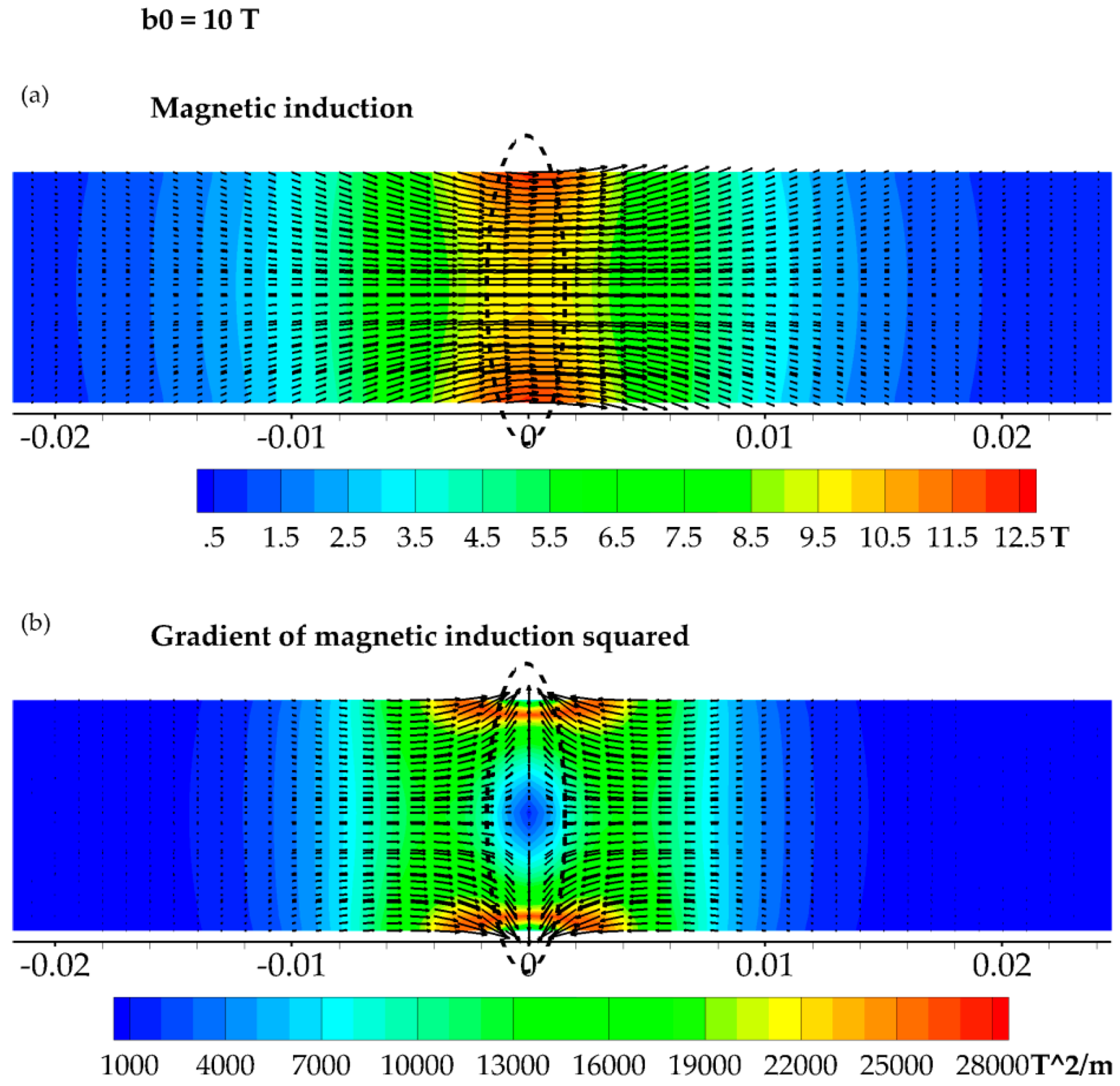
The obtained magnetic field distribution and its characteristics are presented in Figure 3.

3. Results

3.1. Model Validation

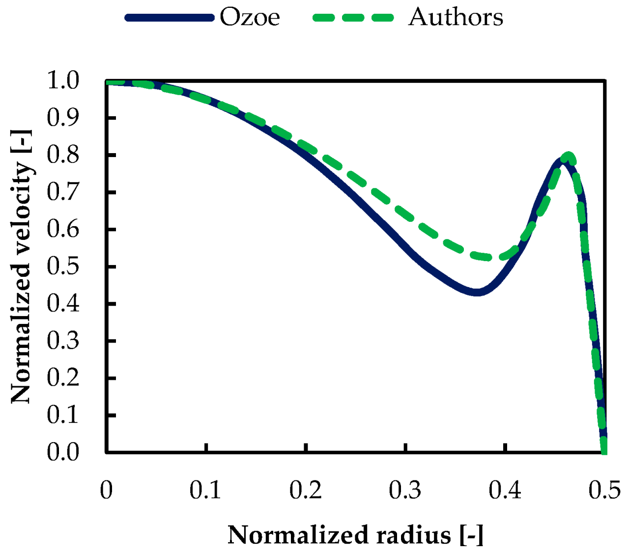
Figure 4 compares the results of Ozoe [15] with those of the authors [23]. The working fluid used in the computations was air (the paramagnetic substance), with magnetic induction in the center of the coil equal to 10 T. Good agreement can be observed as well as the characteristic “M-shaped” profile discussed in more detail in the following sections.

3.2. Referent Case

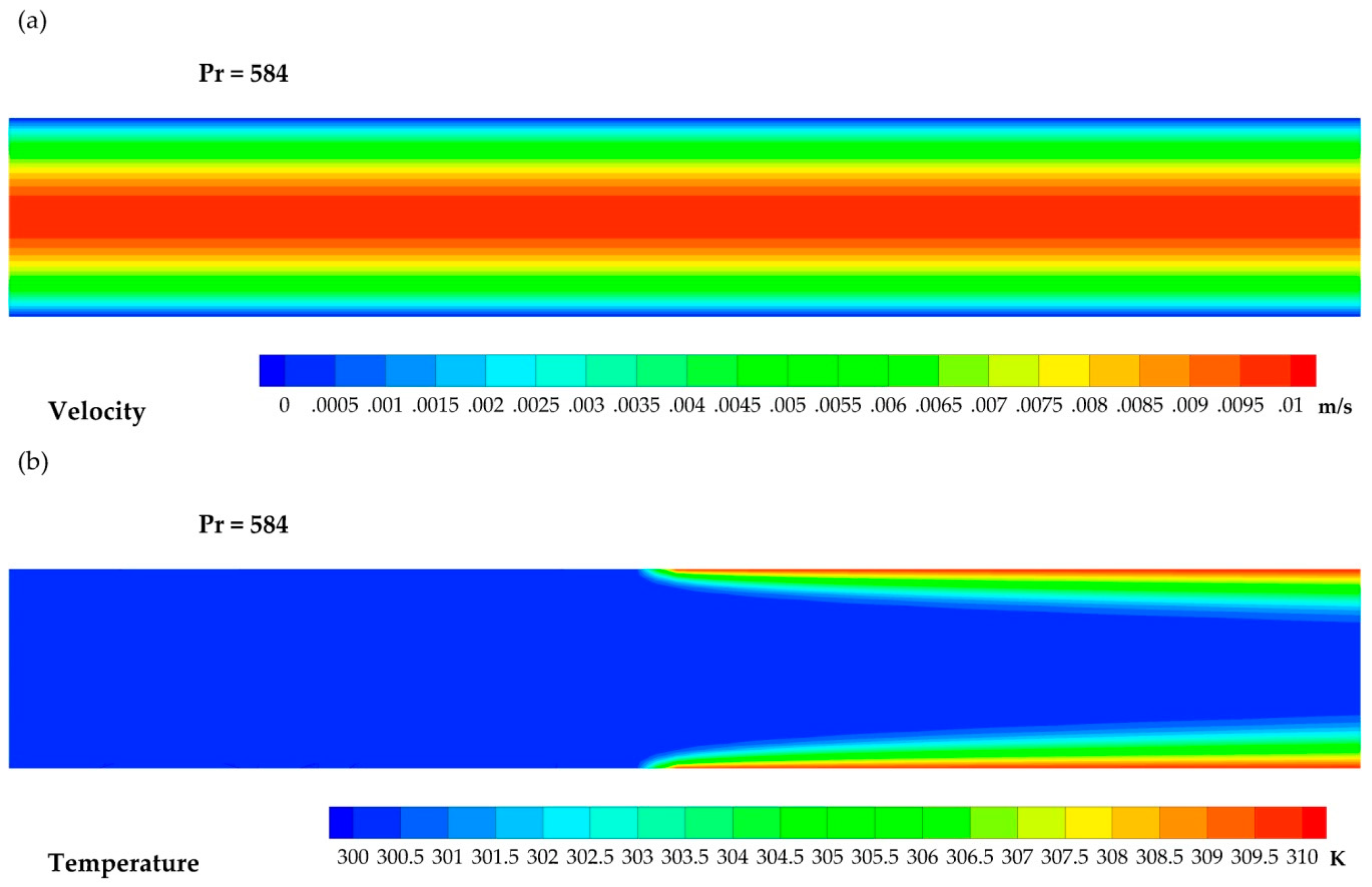
In Figure 5, the flow structure and temperature distribution for the studied comparative case are shown. A typical laminar flow can be observed. The comparative case Prandtl number is equal to 584 [8], which is a basic value for the used working fluid. The velocity and temperature distributions for each value of analyzed Prandtl numbers were similar, and therefore, only one example is shown.

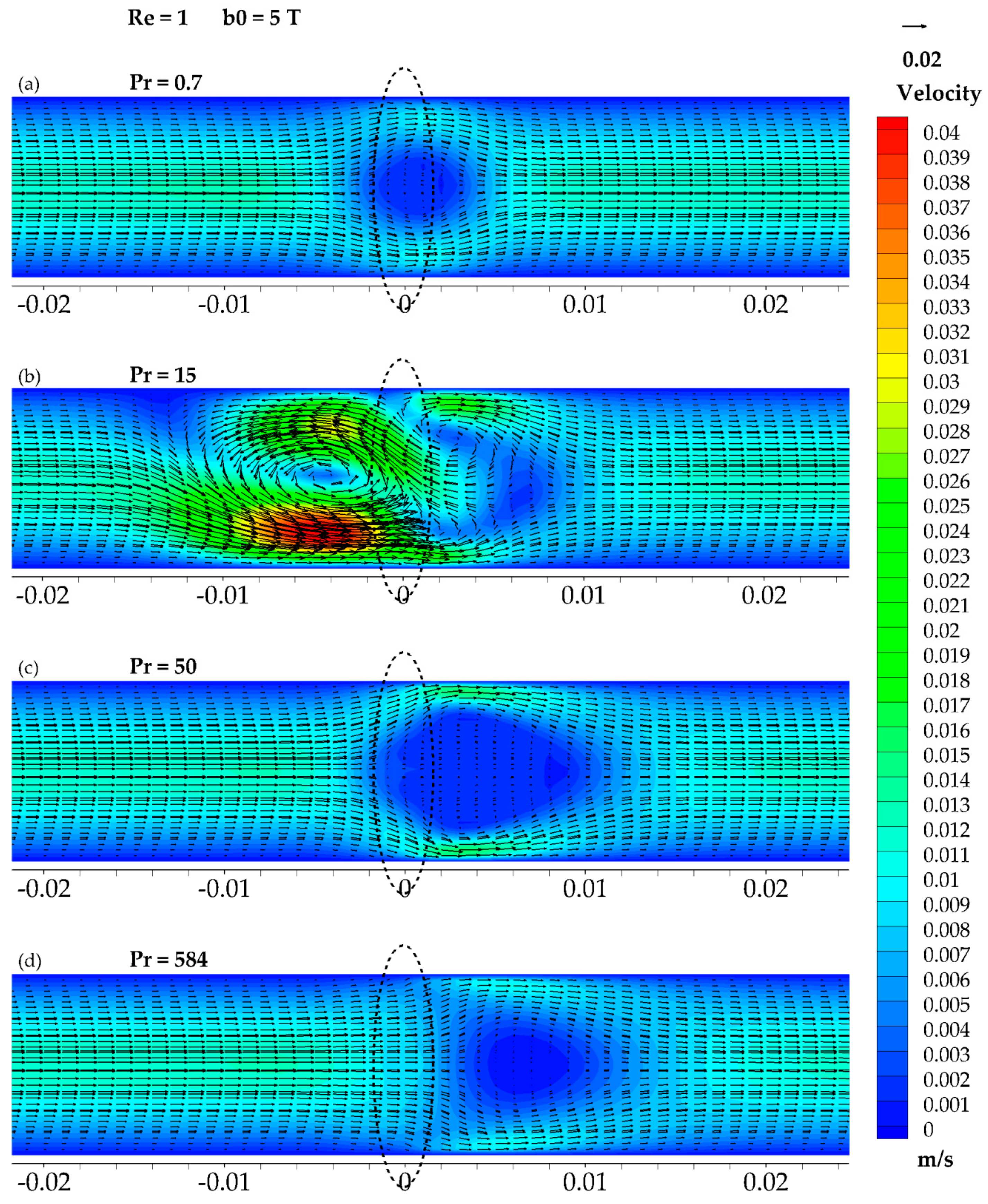
3.3. The Results of Re = 1 and b0 = 5 T

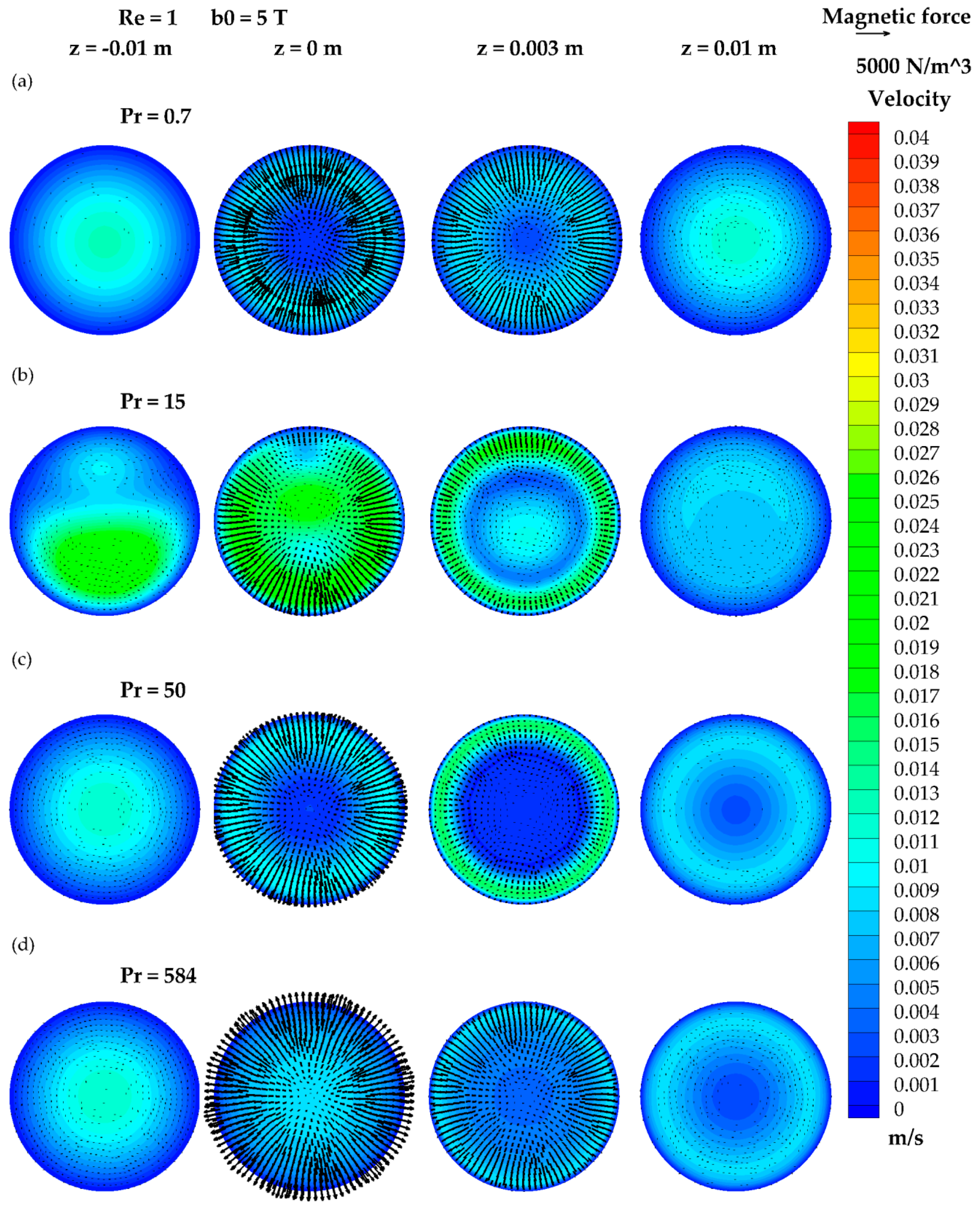
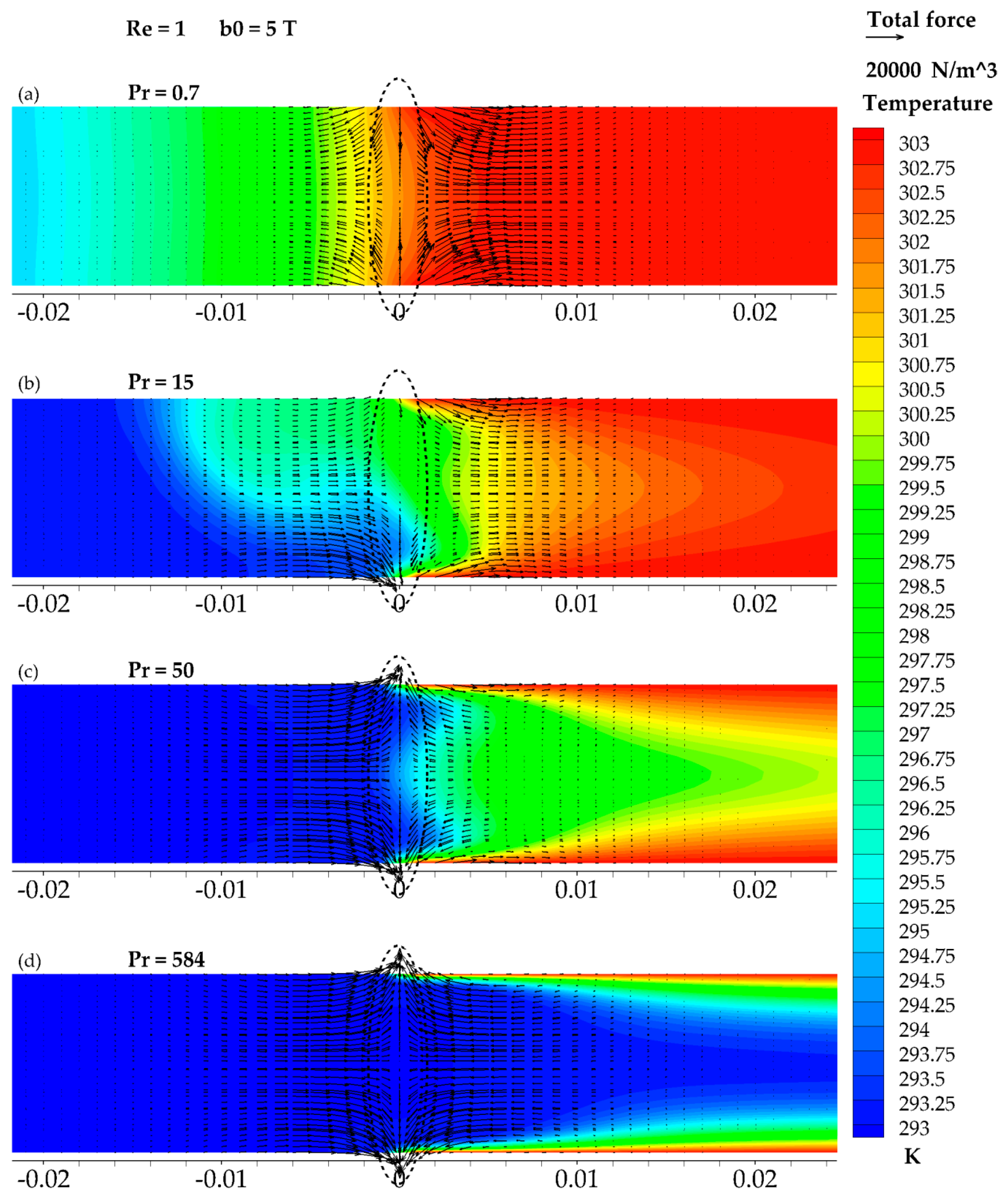
Figure 6, Figure 7 and Figure 8 present the first group of studied cases. This group is characterized by a Reynolds number equal to Re = 1 and a magnetic induction in the center of the coil equal to b0 = 5T with various values of the Prandtl number. The first case refers to a Prandtl number value of Pr = 0.7 (its order of magnitude is characteristic for the air). The impact of the magnetic field on the flow structure (Figure 6a and Figure 7a) resulted in the presence of a medium-sized suppression zone in the area near the flow axis. Near the wall, the thickening of the hydrodynamic boundary layer can be observed. Its reason comes from the fact that the flow concentrated near the wall, and the highest values of velocity can be found there (Figure 7a). The high heat penetration shown in Figure 8a is typical for the flows of a low Prandtl number, and the connection between the magnetic field impact and the temperature distribution remains unclear. Attention should be given to the magnetic force distribution represented by the vector field. The presence of the suppression zone is directly connected with the magnetic force, acting opposite to the flow direction in front of the magnetic coil.
An increase in the fluid Prandtl number value to 15 results in a completely different, complex flow structure. Figure 6b and Figure 7b present the obtained velocity field, where both an axially and a radially asymmetrical structure can be observed. The first velocity field maldistribution is a vortex reaching deep (0.01 m) into the area before the magnetic coil. Fluid inside, it gains a significant (approximately 330%) acceleration in the lower part. In fact, four acceleration zones can be distinguished: The one referred to above, the acceleration zone before the magnetic coil directed inversely to the flow direction, and two small ones after the magnetic coil. It should be noticed that the strong suppression zone forms in the area behind the magnetic coil between the smaller acceleration zones, and its evolution will be observed in the following figures. As mentioned, the structure is slightly shifted in the plane perpendicular to the flow axis. A comparison between Figure 6b and the corresponding temperature distribution (Figure 8b) shows a clear and direct connection between these fields. The vortex allows warmer fluid to penetrate the cold part of the system. The acceleration zones are also linked with the magnetic force direction. This is clearly visible for the highest velocity area.
Figure 6c and Figure 7 present the velocity field for the case of Pr = 50. The flow structure asymmetry is gone, and the magnetic field influence zone moves forward to the area behind the coil. A large recirculation zone appears around the flow axis, giving rise to the characteristic “M-shaped” profile known from many previous papers. The recirculation zone is partially surrounded by the high velocity area near the wall, where a large velocity gradient appears. However, the increase in the velocity value reaches only approximately 30%. There are two combined factors leading to the flow acceleration near the wall. The first of these is the magnetic force acting stream-wise with the flow (Figure 8c). The second one is throttling the flow in the central area by the suppression zone. Both of them lead the fluid to turn towards the wall and, according to Bernoulli’s law, this provides an increase in dynamic pressure, leading directly to the velocity magnitude rise. The temperature distribution shown in Figure 8c behaves similarly to the velocity distribution, and here, the characteristic “M-shaped” profile can also be observed. However, it disappears quickly, even if it still remains in the velocity field in the area further behind the magnetic coil.
Figure 6d, Figure 7d, and Figure 8d present the last case from the first group and refer to the flow of the used working fluid in its basic form. The area influenced by the magnetic field is again pushed forward, which concurs with the tendency presented here. This case is very similar to the previous one in terms of flow structure (Figure 6c,d), yet the effects of the magnetic field influence are vanishing: The fluid acceleration is lower, and the recirculation zone is much smaller. The recirculation zone seems to be surrounded by the middle velocity zone, which appears in the form of a thick shell. The temperature distribution (Figure 8d) is also less responsive to the flow structure than in the previous case. It should be emphasized that the magnetic field influence area is following the temperature distribution (but it should also be remembered that the impact is mutual). In practice, this means that the thermal boundary layer (for high Prandtl number flows as this one) leads to the magnetic field influence being visible further from the location of the magnetic coil. This conclusion is in harmony with the proposed mathematical model, where a lack of significant temperature difference results in a low magnetic field effect or no effect at all.

3.4. The Results of Re = 1 and b0 = 10 T

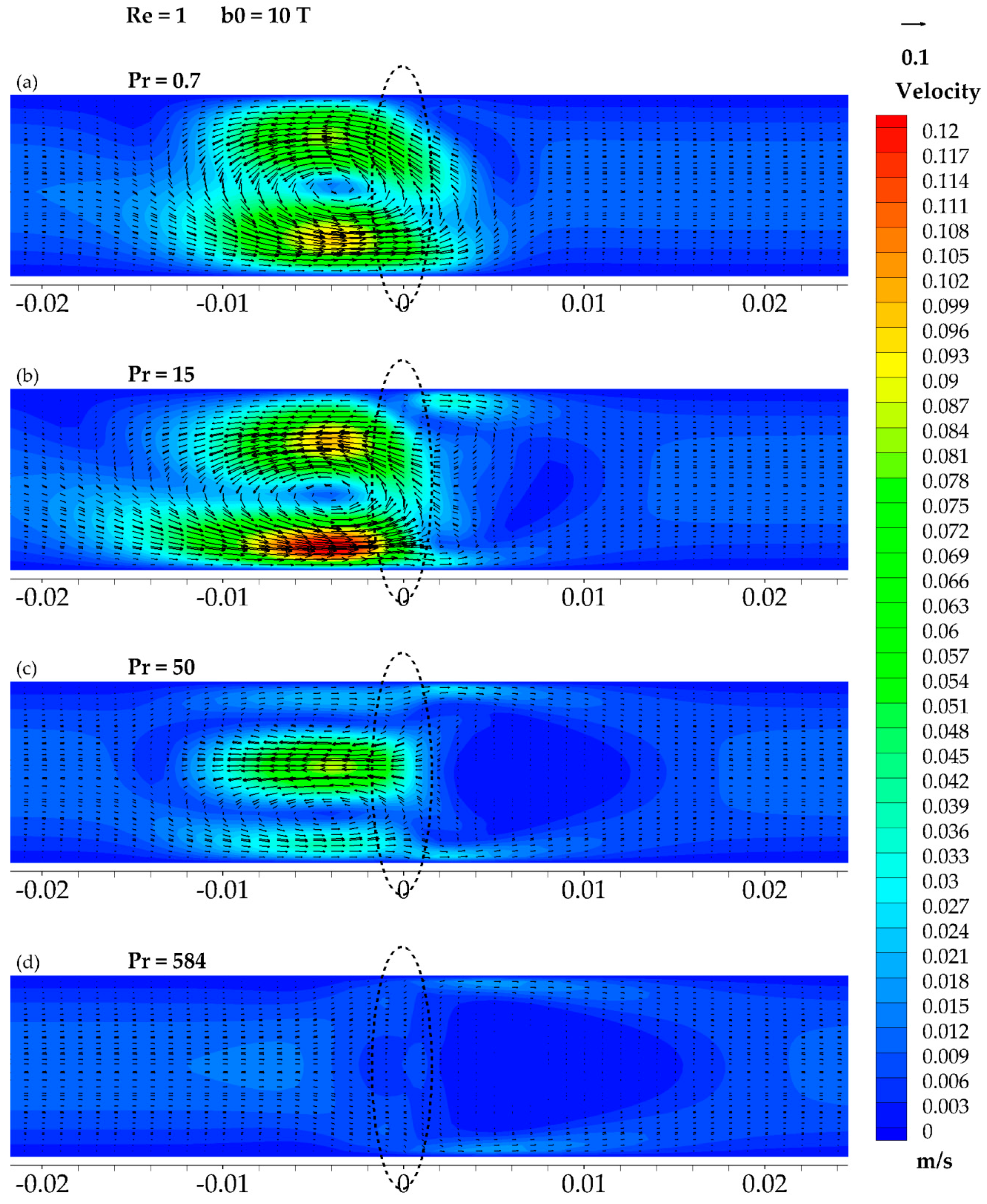
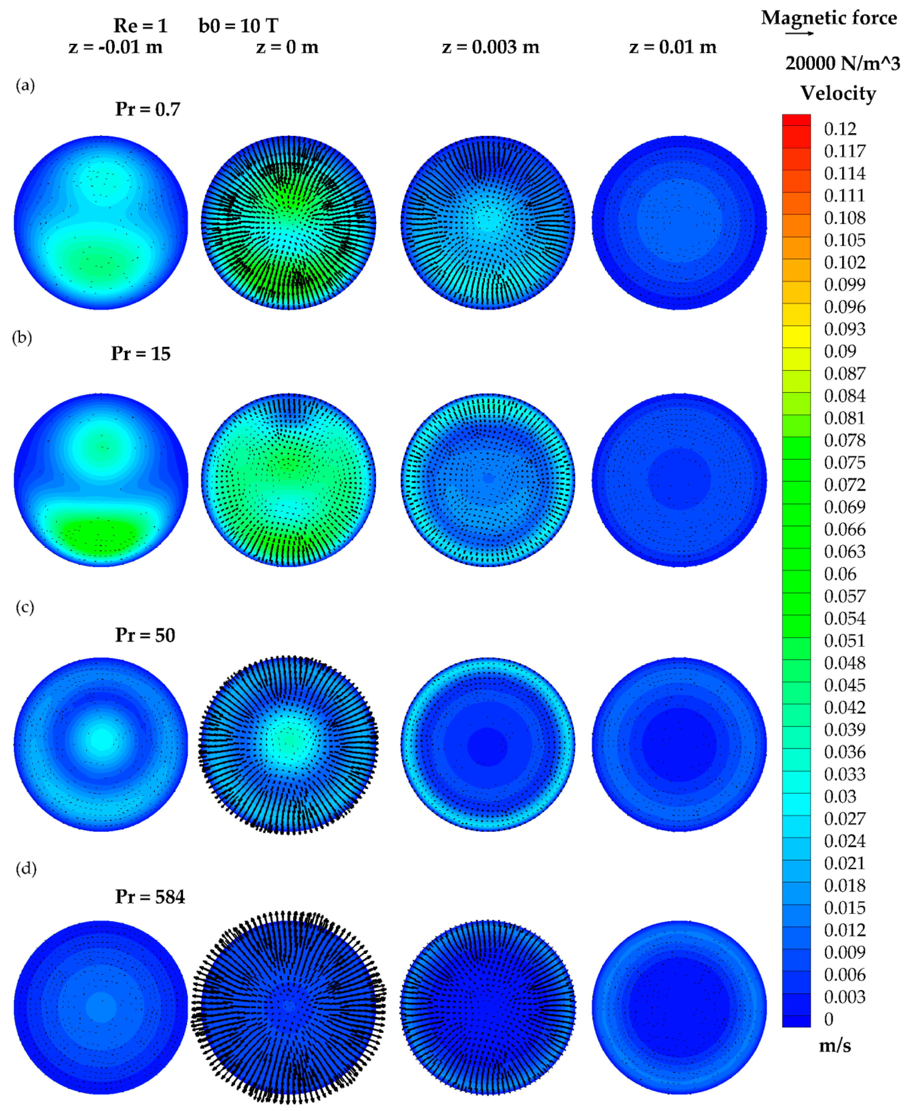
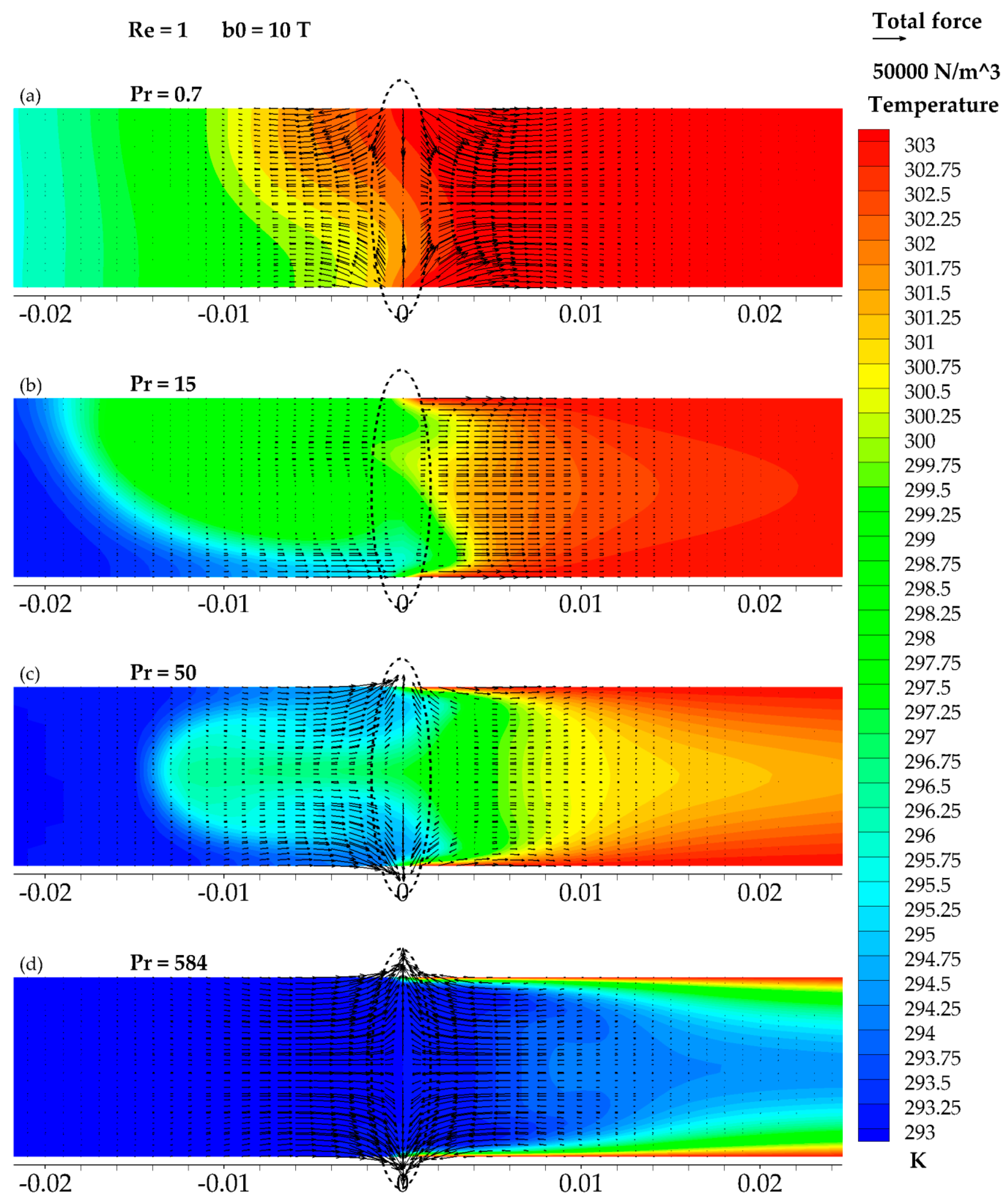
Figure 9, Figure 10 and Figure 11 show the second group of the studied cases. This group is characterized by a Reynolds number equal to Re = 1 and a magnetic induction in the center of the coil equal to b0 = 10T with the same set of Prandtl number values as before. The flow structure obtained for Pr = 0.7 (Figure 9a and Figure 10a) shows no similarity to its predecessor. Before the magnetic coil, a strong vortex structure can be observed. The maximal velocity obtained for this structure exceeds the initial fluid velocity eightfold. The temperature distribution (Figure 11a) shows a visible connection to the velocity field.
Figure 9b and Figure 10b represent the flow structure for the case of a Prandtl number equal to Pr = 15, and once again, both cases of the same Prandtl number behave similarly. The fluid acceleration obtained due to the presence of the magnetic field is, however, much larger than before and exceeds the initial velocity by approximately 10 times in the bottom area before the magnetic coil. On the other hand, the suppression zone behind the coil is formed less clearly than in the previous case of Pr = 15 (Figure 6b and Figure 7b) and, as will be shown in the next figure, gives rise to a different kind of structure. The presence and strength of an obtained vortex structure leads to deep and wide heat penetration of the cold zone of the studied system, as can be noted in Figure 11b. What is interesting, despite the lack of a clear occurrence of an “M-shaped” velocity profile in the velocity field, is that the temperature field near the magnetic field is shaped in this way. However, the regularity of this profile is questionable. Once again, while studying the total force vectors placed on the temperature distribution, direct link between the flow structure and the total acting force direction in the area before the magnetic coil can be clearly seen.
The increase in the Prandtl number value, in the following case, does not provide a symmetrical structure for Pr = 50 as it was observed before at half the strength of magnetic field. This is probably a sign that, for the given conditions, a new type of flow structure (Figure 9c and Figure 10c) occurs. It should be emphasized that this structure is observed and noted for the first time in the research conducted here by the authors. It is characterized by a long, wide, and very strong recirculation zone with the counter-flow core located at the flow axis. The gain in the velocity of the fluid (directed opposite to the initial fluid flow) reaches approximately 600%. Behind the magnetic coil, the largest observed stagnation/recirculation zone can be seen. Its strength, compared to the one before the magnetic coil, might be considered small, but taking into account the "M-shaped" temperature profiles (Figure 11c) in this area, it can be stated that it is comparable to the recirculation zones present in the previous group for Pr = 50 (Figure 6c) or to the next case (Figure 9d). The strong mixing of the fluid by the vortex structure before the coil reveals itself also in the form of temperature maldistribution. In this area, a direct connection between velocity, temperature, and total force fields can be clearly observed.
The final case in the second group refers to Pr = 584, which represents the basic set of working fluid properties. Figure 9d and Figure 10d present the corresponding flow structure. Generally, it consists of, as in the previous cases, an acceleration zone near the wall, a recirculation zone in the middle, and the middle velocity shell in between. Nevertheless, a number of significant and characteristic features should be noticed. The large recirculation zone is preceded by the small stagnation zone and the small acceleration zone. They are both located near the flow axis: The stagnation zone just before the magnetic coil and the local acceleration zone deeper towards the duct inlet. The size of the large recirculation zone forces the hydrodynamic boundary layer to become narrower on the longer section than before. On the other hand, the heat penetration (Figure 11d) is deeper than for the similar case with a smaller magnetic field strength. Moreover, the magnetic field influence area is so large that the return of the velocity profile to its basic, paraboloid form in the section of the pipe shown in the figure cannot be observed.

3.5. The Results of Re = 10 and b0 = 5 T

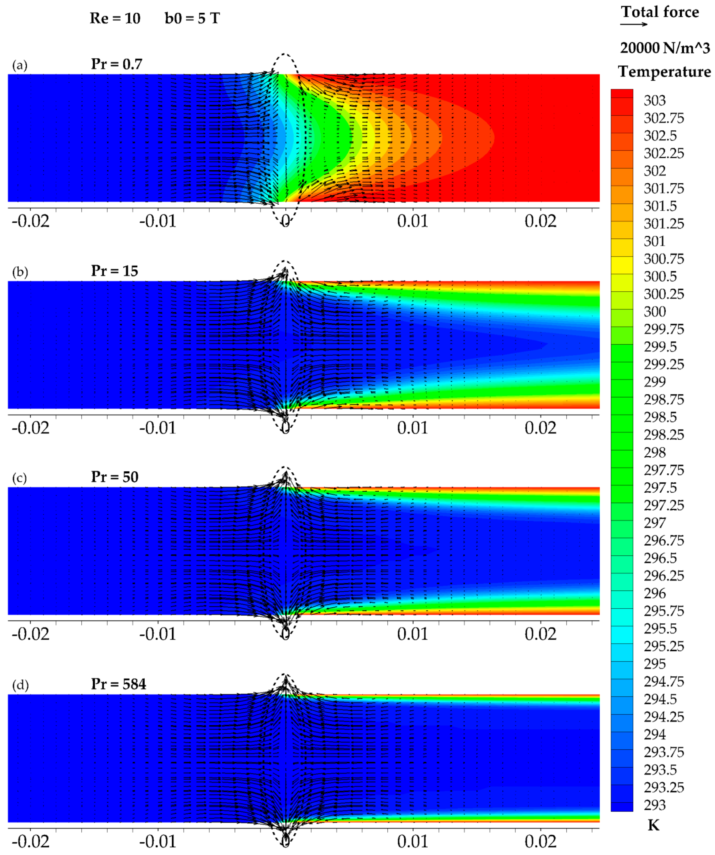
Figure 12, Figure 13 and Figure 14 present the third group of cases and are characterized by a higher Reynolds number value obtained by a tenfold increase in the initial fluid velocity. The magnetic induction in the center of the coil is once again b0 = 5 T.
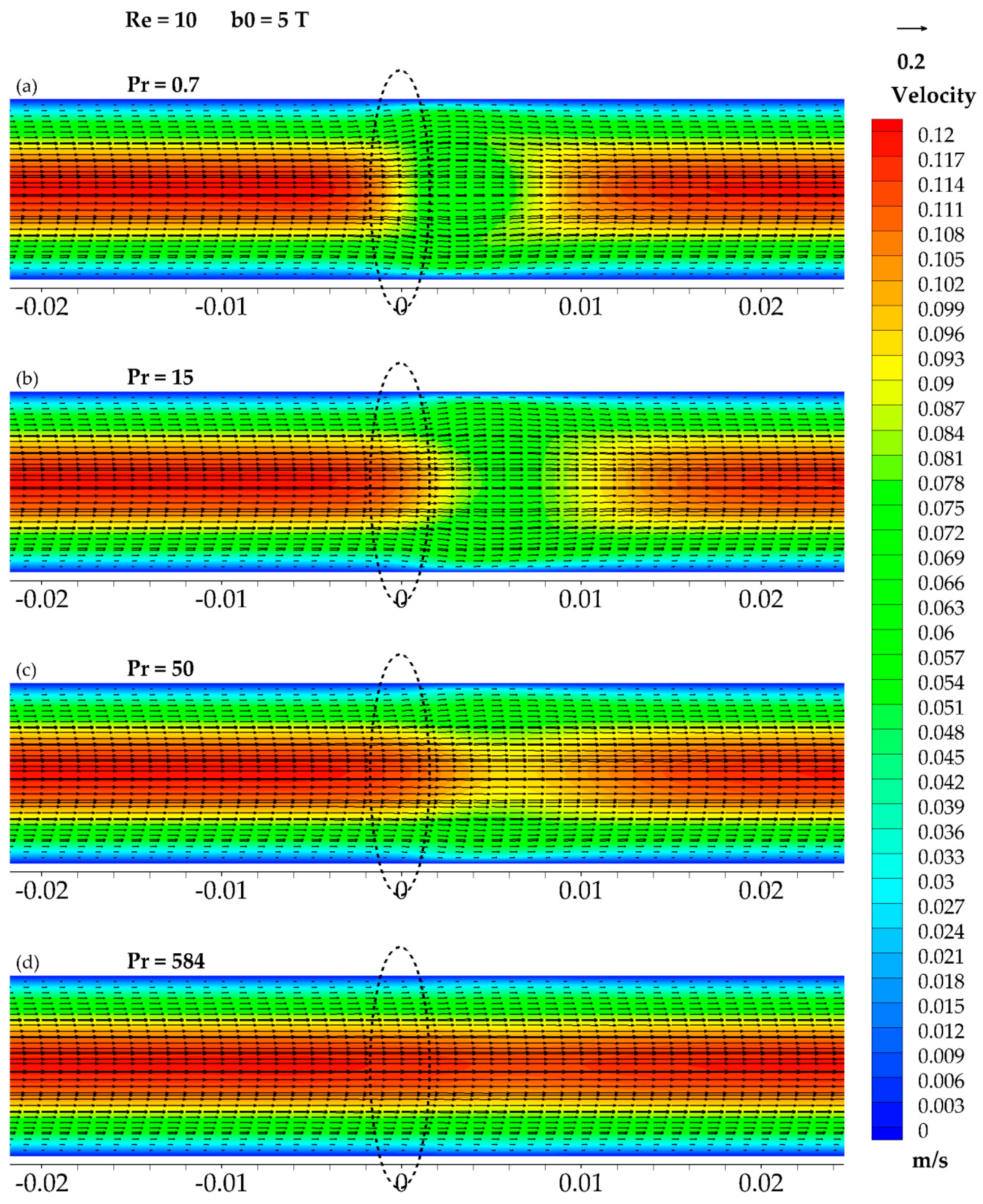
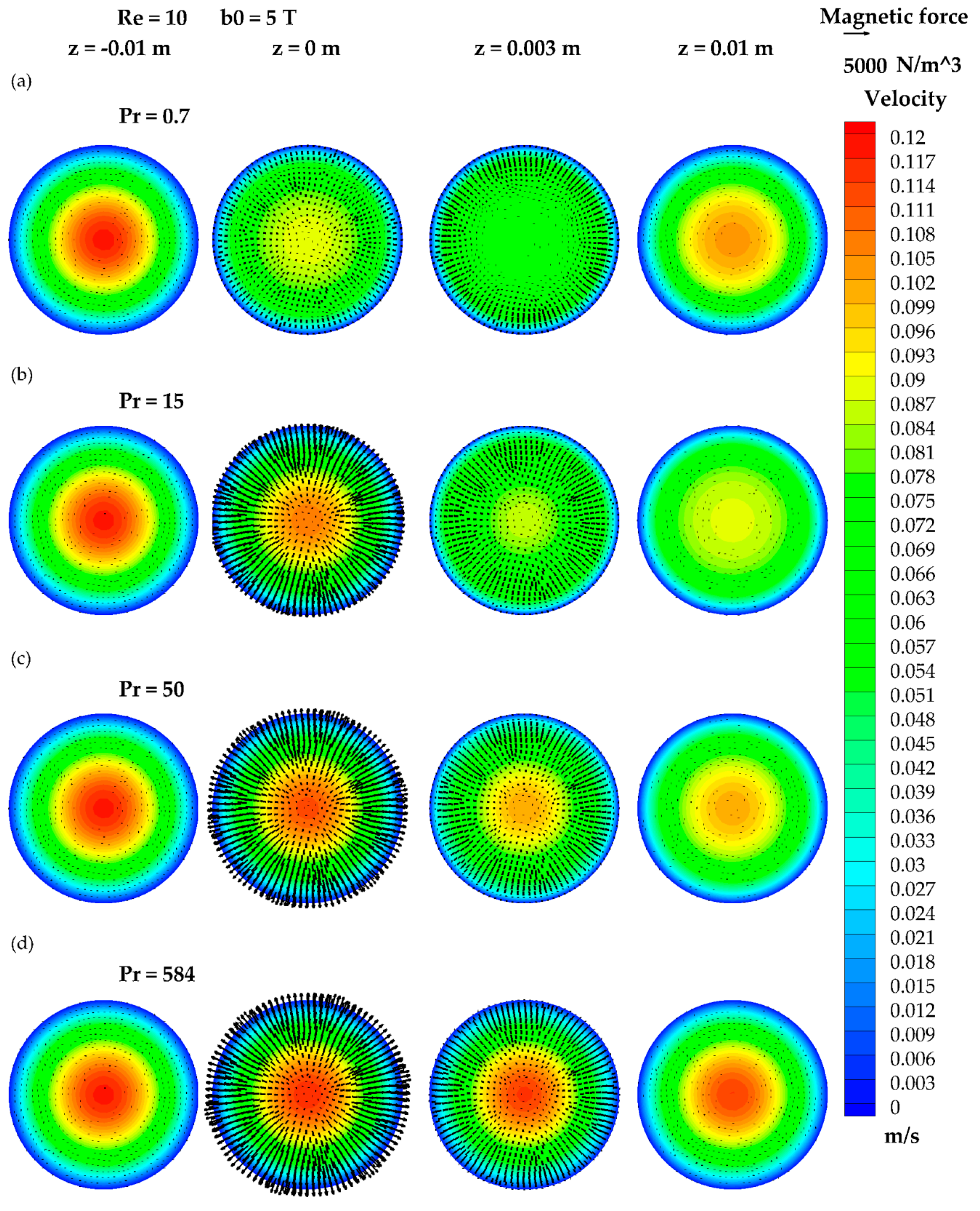
Figure 12a and Figure 13a exhibit the flow structure for the fluid flow characterized by a Prandtl number equal to Pr = 0.7. The presented flow structure is similar to the structure obtained in the first studied group (Figure 6a); however, no suppression zone is present in this case. The fluid is shifted towards the wall in the area directly behind the magnetic coil. An uneven flow suppression can also be observed. The fluid is suppressed in a more serious manner in the area near the flow axis. The temperature distribution (Figure 14a) follows the velocity distribution and exhibits the characteristic “M-shaped” profile.
Figure 12b, Figure 13b, and Figure 14b present the results for the third group case, characterized by a Prandtl number equal to Pr = 15. The velocity field (Figure 12b and Figure 13b) is influenced similarly as in the first case studied in this paper. However, the flow suppression (approximately a 50% decrease) is placed further behind the magnetic coil. The velocity profile is flattened with a thin hydrodynamic boundary layer (high velocity gradient near the wall). The temperature distribution (Figure 14b) is not visibly responding to the magnetic field. As stated earlier, the presence of the temperature gradient drives the thermomagnetic convection and extends the area of magnetic field influence.
Figure 12c and Figure 13c show the impact of a further increase in the Prandtl number value on the flow structure. An increase in the Prandtl number is characterized by the flow thermal boundary layer thickening (Figure 13c). The effect observed in the previous case is vanishing: The velocity profile is less suppressed and less flattened. The area of magnetic field influence is shifted further behind the magnetic coil but is also smaller. The temperature distribution does not respond in a clear, visible way to the magnetic field influence, but it follows velocity distribution, which is affected by the magnetic field.
Figure 12d, Figure 13d, and Figure 14d show the results for the last studied case, characterized by a Prandtl number equal to Pr = 584. The velocity profile (Figure 12d and Figure 13d) experiences a subtle suppression approximately 0.005 m beyond the magnetic coil location. A thinner thermal boundary layer (Figure 14d) can be seen, but the core is characterized by the uniform temperature distribution.

3.6. Velocity Profiles

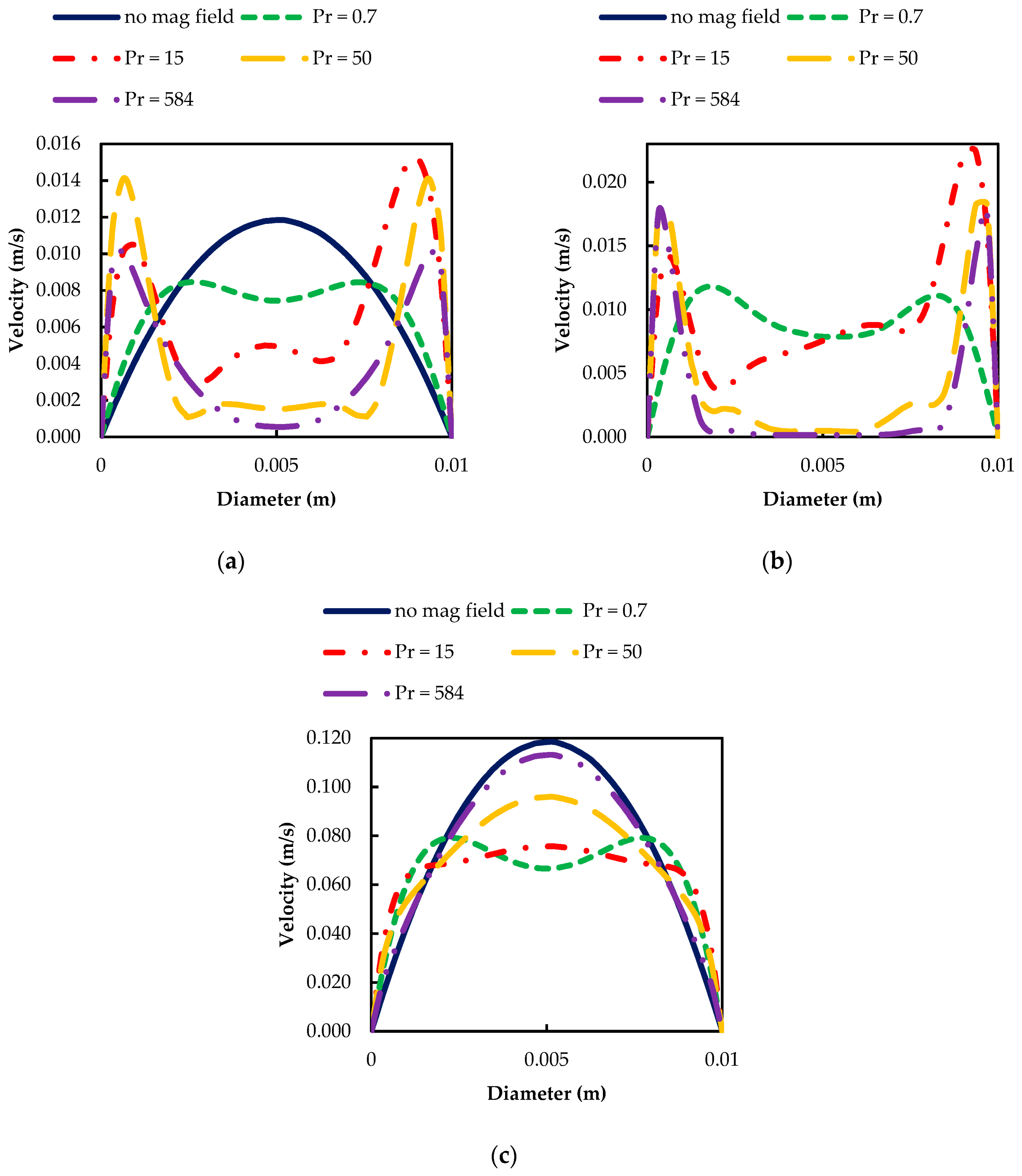
Figure 15 offers further insight into the flow structures of the presented cases. It exhibits velocity profiles in the cross-section perpendicular to the flow axis located 0.005 m behind the magnetic coil. For the two first groups, it can be observed that at this point, the flow structure is mostly symmetrical (Figure 15a,b). In both discussed cases, asymmetry is present for the flows characterized by a Prandtl number equal to Pr = 15 and also Pr = 0.7 for the second group. As can be recalled, these cases had highly complex vortex structures. A rise in the suppression zone as the Prandtl number increases can be observed. At the same time, an area of high acceleration can be found near the wall. These two cases can be treated similarly. However, the variation concerns the scale of the observed maldistributions, and a stronger magnetic field application results in a stronger velocity field maldistribution. It cannot be stated, though, that the effect doubled from the quantitative point of view. The third group (Figure 15c) shows no discrepancies in the field symmetry. It is important to note that the profiles for the cases under the influence of the strong magnetic field are characterized by a lower maximal velocity than the initial laminar flow. No fluid acceleration is observed then, and the effect is limited to larger or smaller suppression of the flow.

3.7. Vorticity Profiles

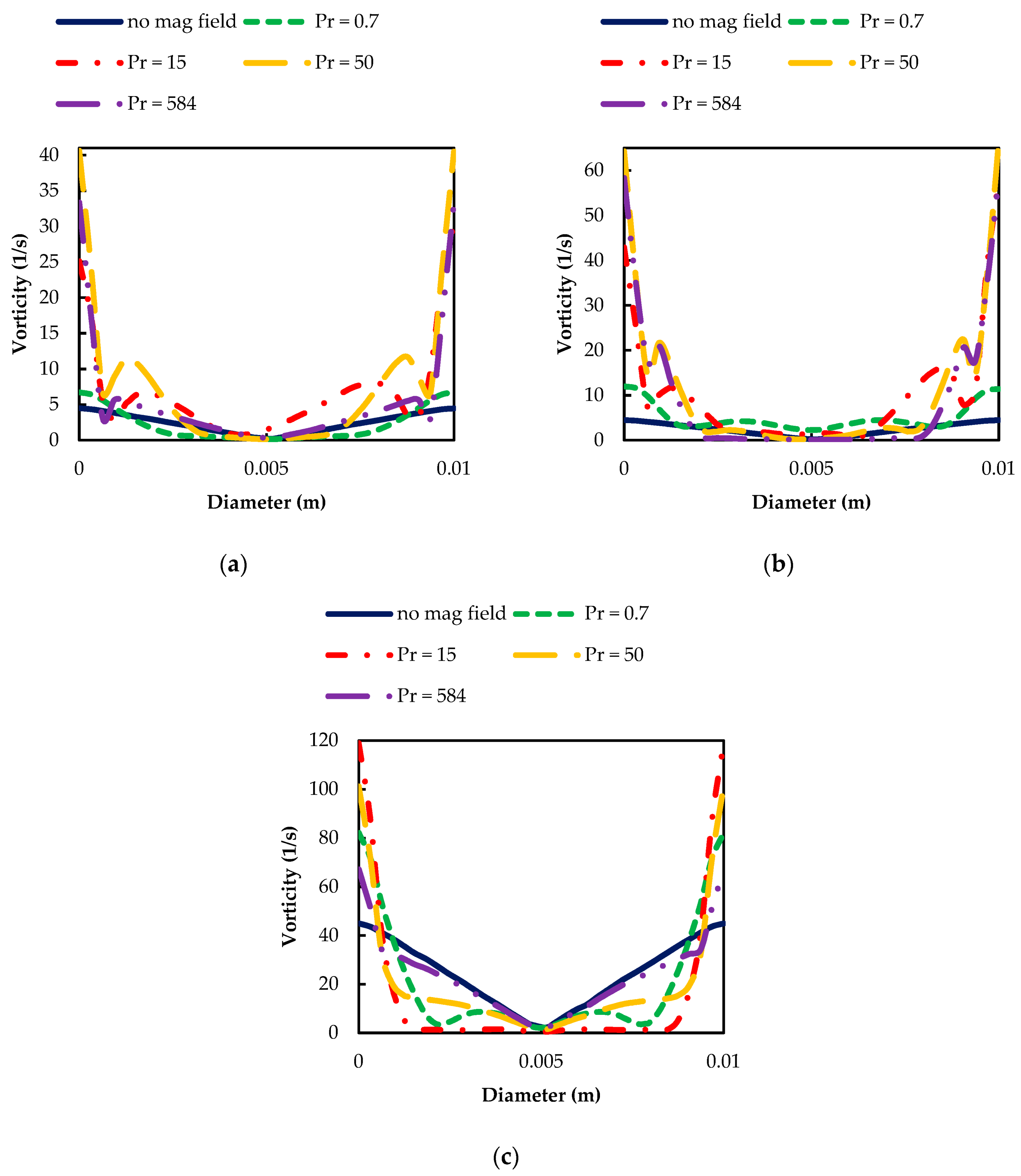
Figure 16 presents the magnetic field impact on the vorticity distribution in the same cross-section as in Figure 15. It should be noticed that in addition to the cases characterized by Pr = 0.7 for all three groups, the presence of the magnetic field strongly influences the vorticity distribution in both shape and quantity. The highest values are observed close to the wall, which is typically a result of interaction between the wall and the fluid. It is also obvious that the highest values are obtained for Re = 10. The appearance of small peaks in the vorticity distribution in Figure 16a,b corresponds with vortical structures caused by the system of forces. In the central part of the pipe, the flow can be treated as non-rotational except in the case of Pr = 15 at 5 T. In Figure 16c, the distribution is mainly governed by the forced convection and depends mostly on the Prandtl number.

3.8. Maximal Velocity

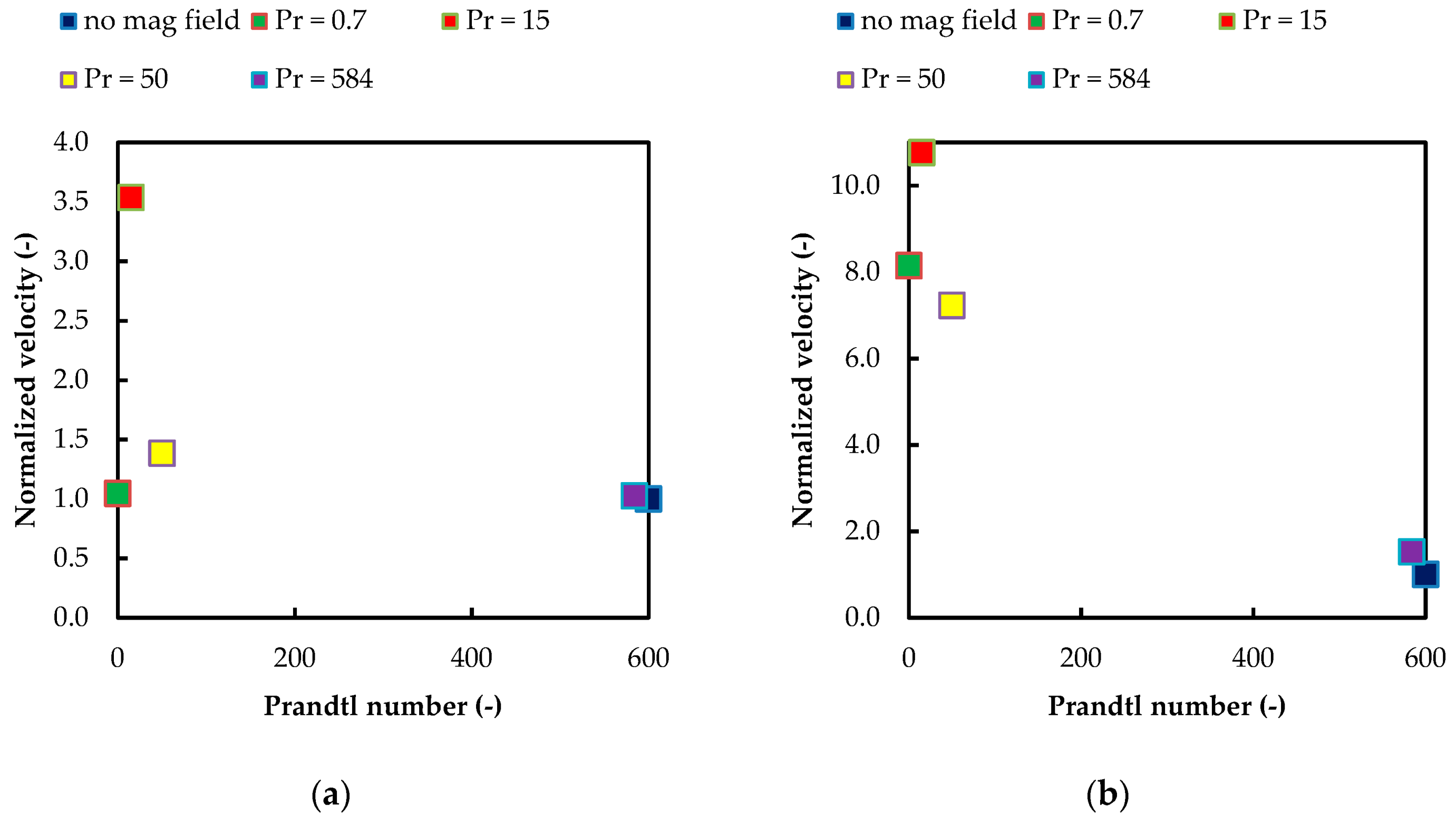
Figure 17 shows the maximal local normalized (referenced to inlet maximal velocity, Equation (10)) flow velocity obtained in the studied cases. Due to the lack of acceleration zones in the third group (Re = 10, b0 = 5T), the results regarding these parameters were omitted in the presented figure. For both groups, the highest acceleration was obtained for the cases of a Prandtl number of Pr = 15, especially in the case with a higher value of the magnetic field induction. However, it should be noted that this acceleration zone is a part of a large recirculation zone, and the local high velocity flow is directed against the initial flow direction. The significant difference can be also seen for the cases of Pr = 0.7. Due to the presence of the strong vortex structure in the second group, the fluid accelerated rapidly in this case, in contrast to the adequate case in the first group.

4. Discussion

The analyzed results reveal the possible existence of three basic flow structure types in the case of the discussed extended Graetz–Brinkman problem (see Table 2).
Low Prandtl number flows are characterized by a symmetrical flow structure, not influenced by the presence of a magnetic field. Then, as the Prandtl number value increases, a different type of structures emerges. It is complex and asymmetrical in nature and possesses the widest area of magnetic field influence, reaching in both directions of the studied duct (treating the magnetic coil as a border). The third type of structure also shows a significant change in the flow structure and temperature distribution versus the typical laminar flow, although it is characterized by the symmetry of the obtained structures in the radial and axial directions.
A number of additional conclusions and hypotheses should be noted. For the symmetrical flow structures, an acceleration effect near the wall is considered to be connected with two factors. The first of these is the presence of a conducive magnetic force, where conducive means streamwise. The second one is the flow throttling by the stagnation zone, which forces fluid to bypass this zone through the narrowed area. This phenomenon, explained by Bernoulli’s principle, leads to the local increment in fluid velocity. It can be also stated that the magnetic field influence area is most likely connected with heat penetration of a certain kind. A rising Prandtl number shifts this area further and further towards the duct outlet. It is not only high temperature gradients that cause the thermomagnetic effect, but also the large area of a near-constant temperature of a specific value. For example, see Figure 9b, in which an area of a slightly higher temperature than the inlet one causes a rise to the strongest acceleration zone of all the studied cases. On the other hand, deep heat penetration with maximum temperature results in far less visible effects, as can be seen in Figure 6a. The presented results show numerous ways of flow structure and temperature distribution modification with the utilization of a strong magnetic field. It should be emphasized that a completely new flow structure was revealed (Figure 9c). The variety of obtained structures leads to the conclusion that from the future application point of view, the ability of the strong magnetic field to shape the flow structure should not be underestimated. However, further research concerning the influence of different factors on the studied phenomenon is necessary to gain greater control over the flow.

Author Contributions

Conceptualization, E.F.-W.; Methodology, E.F.-W. and Ł.P.; Software, Ł.P.; Validation, E.F.-W. and Ł.P.; Formal Analysis, E.F.-W. and Ł.P.; Investigation, Ł.P.; Resources, E.F.-W.; Data Curation, Ł.P. and E.F.-W.; Writing—Original Draft Preparation, Ł.P. and E.F.-W.; Writing—Review & Editing, E.F.-W.; Visualization, Ł.P.; Supervision, E.F.-W.; Project Administration, E.F.-W.; Funding Acquisition, E.F.-W.

Funding

This research received no external funding.

Acknowledgments

The present work was supported by the Polish Ministry of Science.

Conflicts of Interest

The authors declare no conflict of interest.

References

  1. Bednorz, J.G.; Müller, K.A. Possible high Tc superconductivity in the Ba−La−Cu−O system. Z. Phys. B Condens. Matter 1986, 64, 189–193. [Google Scholar] [CrossRef]
  2. Braithwaite, D.; Beaugnon, E.; Tournier, R. Magnetically controlled convection in a paramagnetic fluid. Nature 1991, 354, 134–136. [Google Scholar] [CrossRef]
  3. Wakayama, N.I.; Sugie, M. Magnetic promotion of combustion in diffusion flames. Phys. B Condens. Matter 1996, 216, 403–405. [Google Scholar] [CrossRef]
  4. Ikezoe, Y.; Hirota, N.; Nakagawa, J.; Kitazawa, K. Making water levitate. Nature 1998, 394, 749–750. [Google Scholar] [CrossRef]
  5. Uetake, H. Nonmechanical magnetothermal wind blower by a superconducting magnet. J. Appl. Phys. 1999, 85, 5735–5737. [Google Scholar] [CrossRef]
  6. Tagawa, T.; Shigemitsu, R.; Ozoe, H. Magnetizing force modeled and numerically solved for natural convection of air in a cubic enclosure: Effect of the direction of the magnetic field. Int. J. Heat Mass Transf. 2002, 45, 267–277. [Google Scholar] [CrossRef]
  7. Tagawa, T.; Ujihara, A.; Ozoe, H. Numerical computation for Rayleigh–Benard convection of water in a magnetic field. J. Heat Mass Transf. 2003, 46, 4097–4104. [Google Scholar] [CrossRef]
  8. Bednarz, T. Numerical and Experimental Analyses of Convection of Paramagnetic Fluid in a Cubic Enclosure. Ph.D. Thesis, Kyushu University, Fukuoka, Japan, 2004. [Google Scholar]
  9. Filar, P. Convection of Paramagnetic Fluid in a Cylindrical Enclosure under a Strong Magnetic Field. Ph.D. Thesis, Kyushu University, Fukoka, Japan, 2004. [Google Scholar]
  10. Roszko, A.; Fornalik-Wajs, E. Extend of magnetic field interference in the natural convection of diamagnetic nanofluid. Heat Mass Transf. 2018, 54, 2243–2254. [Google Scholar] [CrossRef]
  11. Kraszewska, A.; Pyrda, Ł.; Donizak, J. High magnetic field impact on the natural convection behaviour of a magnetic fluid. Heat Mass Transf. 2018, 54, 2383–2394. [Google Scholar] [CrossRef]
  12. Wróbel, W.; Fornalik-Wajs, E.; Szmyd, J.S. Analysis of the influence of a strong magnetic field gradient on convection process of paramagnetic fluid in the annulus between horizontal concentric cylinders. J. Phys. Conf. Ser. 2012, 395. [Google Scholar] [CrossRef]
  13. Fornalik-Wajs, E.; Filar, P.; Wajs, J.; Roszko, A.; Pleskacz, Ł.; Ozoe, H. Flow structure, heat transfer and scaling analysis in the case of thermo-magnetic convection in a differentially heated cylindrical enclosure. J. Phys. Conf. Ser. 2014, 503. [Google Scholar] [CrossRef]
  14. Kenjeres, S.; Tjin, J.L. Numerical simulations of targeted delivery of magnetic drug aerosols in the human upper and central respiratory system: A validation study. R. Soc. Open Sci. 2017, 4, 170873. [Google Scholar] [CrossRef] [PubMed]
  15. Ozoe, H. Magnetothermal wind tunnel. In Magnetic Convection, 1st ed.; Imperial College Press: London, UK, 2005; pp. 193–204. ISBN 10: 1-86094-578-3. [Google Scholar]
  16. Pleskacz, L.; Fornalik-Wajs, E. Magnetic field impact on the high and low Reynolds number flows. J. Phys. Conf. Ser. 2014, 530. [Google Scholar] [CrossRef]
  17. Pleskacz, L.; Roszko, A.; Fornalik-Wajs, E. Velocity and temperature maldistribution due to the magnetic field influence. Sci. Lett. Rzeszow Univ. Technol. Mech. 2014, 31, 425–432. [Google Scholar] [CrossRef] [Green Version]
  18. Pleskacz, L.; Fornalik-Wajs, E. Various aspects of magnetic field influence on forced convection. E3S Web Conf. 2016, 10. [Google Scholar] [CrossRef]
  19. Pleskacz, L.; Fornalik-Wajs, E. Low Reynolds number flow’s heat transfer influenced by strong magnetic field. J. Phys. Conf. Ser. 2016, 745. [Google Scholar] [CrossRef]
  20. Patankar, S.V. Numerical Heat Transfer and Fluid Flow, 1st ed.; CRC Press: Boca Raton, FL, USA, 1980; ISBN 0-89116-522-3. [Google Scholar]
  21. Jackson, J.D. Classical Electrodynamics, 2nd ed.; John Wiley & Sons, Inc.: New York, NY, USA, 1975; ISBN 10: 047143132X. [Google Scholar]
  22. Revision Notes on Magneto-static and Magnetic Effect of Current. Available online: https://www.askiitians.com/revision-notes-new/physics/magnetostatic-and-magnetism.html (accessed on 9 January 2019).
  23. Pleskacz, L. Numerical Analysis of the Magnetic Field Influence on the Velocity and Temperature Fields in a Duct of Various Geometry. Master’s Thesis, AGH University of Science and Technology, Cracow, Poland, 2013. [Google Scholar]
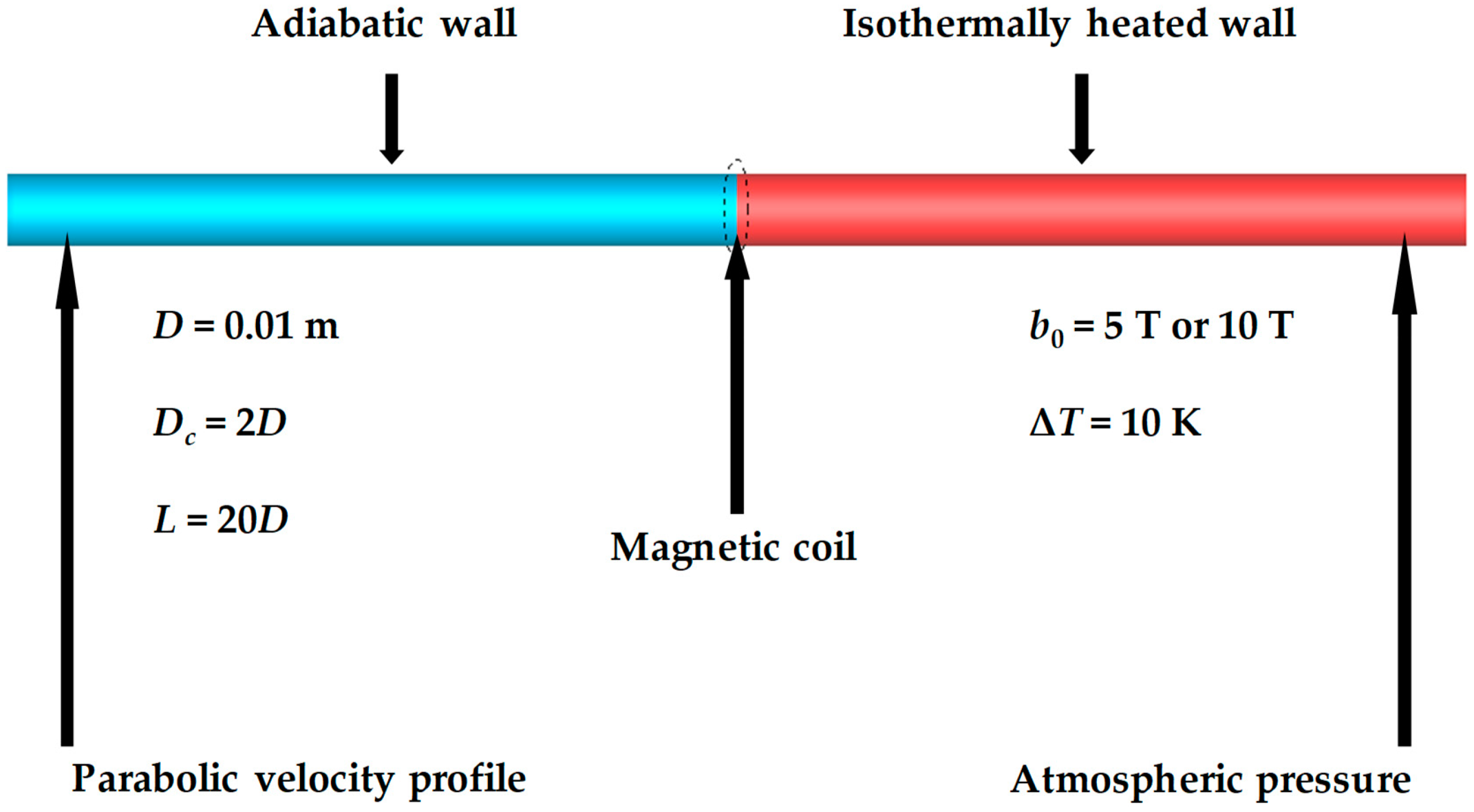
Figure 1. The studied case geometry, important parameters, and boundary conditions.
Fluids 04 00036 g001
Figure 2. Schematic view of the approach to Biot–Savart’s law computation (own drawing based on the idea from [22]).
Fluids 04 00036 g002
Figure 3. The distribution of magnetic field obtained in the computations: (a) Magnetic induction distribution, (b) gradient of magnetic induction squared.
Fluids 04 00036 g003
Figure 4. Comparison between literature results based on Ozoe [15] and the authors’ results: Normalized velocity profile versus normalized pipe radius.
Fluids 04 00036 g004
Figure 5. Flow without the influence of the magnetic field, Prandtl number equal to 584: (a) Velocity field; (b) temperature field.
Fluids 04 00036 g005
Figure 6. Flow structure in the axial cross-section at Re = 1 and b0 = 5 T: (a) Pr = 0.7, (b) Pr = 15, (c) Pr = 50, (d) Pr = 584.
Fluids 04 00036 g006
Figure 7. Flow structure in the radial cross-sections (z = −0.01 m, 0 m, 0.003 m, 0.01 m) at Re = 1 and b0 = 5 T: (a) Pr = 0.7, (b) Pr = 15, (c) Pr = 50, (d) Pr = 584.
Fluids 04 00036 g007
Figure 8. Temperature and total force distribution in the axial cross-section at Re = 1 and b0 = 5 T: (a) Pr = 0.7, (b) Pr = 15, (c) Pr = 50, (d) Pr = 584.
Fluids 04 00036 g008
Figure 9. Flow structure in the axial cross-section at Re = 1 and b0 = 10 T: (a) Pr = 0.7, (b) Pr = 15, (c) Pr = 50, (d) Pr = 584.
Fluids 04 00036 g009
Figure 10. Flow structure in the radial cross-sections (z = −0.01 m, 0 m, 0.003 m, 0.01 m) at Re = 1 and b0 = 10 T: (a) Pr = 0.7, (b) Pr = 15, (c) Pr = 50, (d) Pr = 584.
Fluids 04 00036 g010
Figure 11. Temperature and total force distribution in the axial cross-section at Re = 1 and b0 = 10 T: (a) Pr = 0.7, (b) Pr = 15, (c) Pr = 50, (d) Pr = 584.
Fluids 04 00036 g011
Figure 12. Flow structure in the axial cross-section at Re = 10 and b0 = 5 T: (a) Pr = 0.001, (b) Pr = 15, (c) Pr = 50, (d) Pr = 584.
Fluids 04 00036 g012
Figure 13. Flow structure in the radial cross-sections (z = −0.01 m, 0 m, 0.003 m, 0.01 m) at Re = 10 and b0 = 5 T: (a) Pr = 0.001, (b) Pr = 15, (c) Pr = 50, (d) Pr = 584.
Fluids 04 00036 g013
Figure 14. Temperature and total force distribution in the axial cross-section at Re = 10 and b0 = 5 T: (a) Pr = 0.001, (b) Pr = 15, (c) Pr = 50, (d) Pr = 584.
Fluids 04 00036 g014
Figure 15. Velocity profiles obtained for the studied cases in the cross-section placed 0.005 m behind the magnetic coil: (a) Re = 1, b0 = 5 T, (b) Re = 1, b0 = 10 T, (c) Re = 10, b0 = 5 T.
Fluids 04 00036 g015
Figure 16. Vorticity profiles obtained for the studied cases in the cross-section placed 0.005 m behind the magnetic coil: (a) Re = 1, b0 = 5 T, (b) Re = 1, b0 = 10 T, (c) Re = 10, b0 = 5 T.
Fluids 04 00036 g016
Figure 17. Maximal flow velocities values versus the Prandtl number value: (a) Re = 1, b0 = 5 T, (b) Re = 1, b0 = 10 T.
Fluids 04 00036 g017
Table 1. Working fluid properties [8].
PropertySymbolUnitValue
Densityρkg/m31463
Specific HeatcJ/(kg·K)4182
Dynamic ViscosityμPa·s0.08689
Thermal Expansion Coefficient β K−10.52 × 10⁻³
Volumetric Magnetic Susceptibility χ v -3.38 × 10⁻⁴
Magnetic PermeabilityμmH/m4π × 10−7
Thermal ConductivityλW/(m·K)0.6
Table 2. General description of flow structure types.
I TypeII TypeIII Type
Low Prandtl number value ≪ 1Medium Prandtl number value approx. 15–50High Prandtl number value > 100
SymmetricalAsymmetricalSymmetrical
Intact by the magnetic fieldStrongly dependent on the magnetic fieldStrongly dependent on the magnetic field