Article

Structural Analysis and Optimization of a Propeller Under Separate Air and Water Operating Conditions Using One-Way Fluid–Structure Coupling

1
Salt Lake Chemical Engineering Research Complex, School of Chemical Engineering, Qinghai University, Xining 810016, China
2
HohhotInner Mongolia Power Group Alxa Power Supply Company, Alashan 750300, China
*
Authors to whom correspondence should be addressed.
Fluids 2026, 11(9), 225; https://doi.org/10.3390/fluids11090225
Submission received: 9 July 2026 / Revised: 13 August 2026 / Accepted: 13 August 2026 / Published: 7 September 2026
(This article belongs to the Section Mathematical and Computational Fluid Mechanics)

Abstract

A propeller intended for aerial–aquatic vehicles must maintain adequate propulsive performance and structural reliability in both air and water, where the fluid properties and load levels differ substantially. This study presents an engineering workflow combining blade element momentum theory (BEMT), computational fluid dynamics (CFD), and one-way fluid–structure coupling to evaluate a propeller under separate air and water operating conditions. Candidate geometries were first screened using a two-stage BEMT procedure. The selected baseline configuration was subsequently analyzed by CFD under three steady operating conditions: air start, water start, and water inflow. The resulting non-uniform surface pressures and centrifugal loads were transferred to a finite element model. The blade root transition was identified as the dominant stress concentration region under all conditions, and the water inflow case produced the most critical structural response, with a maximum von Mises stress of 129.8 MPa and a maximum deformation of 5.378 mm. After local blade root optimization, these values decreased to 87.0 MPa and 3.669 mm, respectively. The proposed workflow provides an efficient approach for preliminary structural assessment and local optimization of propellers operating separately in air and water. The transient air–water interface-crossing process and associated multiphase effects are beyond the scope of the present study.

1. Introduction

Cross-medium aerial–aquatic vehicles have attracted increasing attention because they can operate across the air–water interface and combine the mobility advantages of aerial and underwater systems. Existing reviews and prototype studies have shown rapid progress in vehicle architectures, transition strategies, and actuation concepts, but they also indicate that propulsion-system compatibility across radically different media remains a core bottleneck [1,2,3,4,5,6,7]. In particular, a propeller intended to function in both air and water must tolerate pronounced differences in fluid density, pressure loading, and structural demand while still maintaining acceptable propulsive performance. This positioning of the topic within current aerial–aquatic vehicle research is supported by recent reviews and experimental robot studies [3,4,5,6,7].
Previous studies on hybrid aerial–aquatic propulsion have focused mainly on propulsion efficiency, transition performance, vehicle configuration, or control strategy, whereas the structural response of the same propeller across multiple media has received less systematic attention [3,4,5,6,7,8,9]. Recent work on hybrid aerial–aquatic propellers, aerial–aquatic vehicle configurations, and trans-medium strategies confirms that propulsion design is often discussed from the perspective of thrust and maneuverability, with less emphasis on multi-condition structural safety. The existing literature on marine and composite propellers further shows that fluid–structure interaction can significantly affect deformation, stress distribution, and load transfer near the blade root, especially under non-uniform loading. These studies justify a stronger structural focus for the present manuscript [10,11,12,13,14,15,16,17,18,19,20].
For preliminary engineering design, one-way fluid–structure coupling provides an efficient way to link flow-induced pressure loads with structural response when the reverse influence of deformation on the flow field is expected to remain limited [11,12,13,14,15,16,17,18,19,20]. This approximation is commonly adopted in rotating machinery and propeller analysis when the objective is to identify critical conditions, weak regions, and optimization targets rather than to resolve fully transient two-way interaction. At the same time, BEMT remains attractive for initial geometry screening because of its computational efficiency, whereas CFD is needed to recover three-dimensional pressure distributions for structural analysis [21,22,23,24,25].
Against this background, the present study aims to establish an engineering workflow for the structural analysis and local optimization of a cross-medium propeller. The specific objectives are to determine a baseline scheme through two-stage BEMT screening; extract pressure loads under air start, water start, and water inflow conditions by CFD; compare structural responses through one-way fluid–structure coupling; and identify and optimize the critical blade root region. The original manuscript already contains the essential numerical framework and results on which this revised version is based.

2. Mathematical Model

2.1. Preliminary Design and BEMT Screening

The preliminary design stage was carried out using blade element momentum theory. In this approach, the rotating blade is discretized into spanwise blade elements, and local airfoil forces are coupled with actuator disk momentum relations to estimate thrust, torque, and efficiency. Because BEMT is computationally efficient and well suited to parametric comparison, it was used here only for preliminary screening rather than for structural load extraction. The detailed pressure field required for structural analysis was obtained later by CFD [21,22,23,24,25].
In the blade element formulation, a differential blade element of radial width (dr) is considered at the radial position (r). The propeller rotates at an angular velocity (Ω), while the local chord length and blade pitch angle are denoted by (c) and (β), respectively. The local velocity triangle adopted in the BEMT formulation is illustrated in Figure 1. Accounting for the axial and tangential induction factors, (a) and (a′), respectively, the local axial velocity, tangential velocity, resultant relative velocity, and inflow angle are expressed as:
V a =   V 0 ( 1 + a )
V t = Ω r ( 1 a )
W = ( V a 2 + V t 2 )
φ = arctan V a V t
As shown in Figure 1, Va and Vt represent the axial and tangential components of the local relative flow velocity, respectively, and (W) is their resultant. The inflow angle (Φ) is defined as the angle between (W) and the plane of rotation, whereas the local blade pitch angle (β) is measured between the blade chord line and the plane of rotation. Accordingly, the local angle of attack is determined by
α = β ϕ
The calculated angle of attack is subsequently used to obtain the corresponding lift and drag coefficients, (CL) and (CD), from the airfoil characteristics. This velocity triangle representation provides a direct geometric interpretation of Equations (1)–(4) and clarifies the relationship among the local velocity components, inflow angle, blade pitch angle, and angle of attack.
d L = 0.5 ρ W 2 c C L d r
d D = 0.5 ρ W 2 c C D   d r
ω = 2 π n / 60
where V0 denotes the axial inflow velocity; W is the resultant relative velocity at the blade element; ϕ and α are the inflow angle and angle of attack, respectively; CL and CD denote the airfoil lift and drag coefficients, respectively; B is the number of blades; and ρ is the fluid density. Resolving the elemental lift and drag forces into the axial and circumferential directions yields the differential thrust and torque. Accordingly, the blade element contributions to thrust and torque are expressed as follows:
d T = B ( d L cos φ d D sin φ )
d Q = Br ( d L sin φ + d D cos φ )
In the momentum theory formulation, the propeller is modeled as an ideal actuator disk. By applying axial and angular momentum conservation to an annular stream tube of radius r and thickness dr, the differential thrust and torque are obtained as follows:
d T = 4 π p r V 0 2 a ( 1 + a ) d r
d Q = 4 π p r 3 V 0 Ω ( 1 + a ) a d r
BEMT is typically solved using an iterative procedure. First, the radial position of each blade element and the initial axial and tangential induction factors, (a) and (a’), are specified based on the impeller geometry, rotational speed, incoming flow velocity, and fluid properties. The relative velocity (W), inflow angle (φ), and angle of attack (α) are then determined from the velocity triangle, while the lift and drag coefficients (CL) and (CD) are obtained from the corresponding airfoil characteristics. Subsequently, the elemental thrust and torque are calculated using the blade element and momentum formulations, and the induction factors are updated accordingly. This iterative process is repeated until convergence is achieved, thereby completing the solution for the blade element.
By integrating the contributions of all blade elements along the radial direction, the overall thrust (T), torque (Q), and efficiency (η) of the impeller can be obtained. The efficiency is expressed as follows:
η = T V 0 Q Ω
As a reduced-order engineering method, BEMT cannot fully resolve complex three-dimensional and unsteady flow phenomena, such as flow separation, tip vortex evolution, and localized pressure gradients near the blade root [22,26,27,28,29,30,31]. It is therefore employed only for candidate ranking and baseline configuration selection. The nonuniform blade surface pressures used for structural analysis are obtained from three-dimensional CFD simulations and transferred to the finite element model through one-way fluid–structure interaction. The results of the two-stage BEMT screening are summarized in Table 1 and Table 2.
Because propulsive efficiency provides the most comprehensive measure of the overall propulsive performance of the propeller, followed by thrust capability, whereas power consumption primarily serves as a constraint, weights of 0.50, 0.35, and 0.15 are assigned to these three indicators, respectively. The scores for the water and air operating conditions are defined as follows:
S w = 0.50 η w * + 0.35 C T , w * + 0.15 C P , w *
S a = 0.50 η a * + 0.35 C T a * + 0.15 C P , a *
The final composite score is expressed as:
S c o r e = 0.60 S w + 0.40 S a - 0.10 | S w - S a |
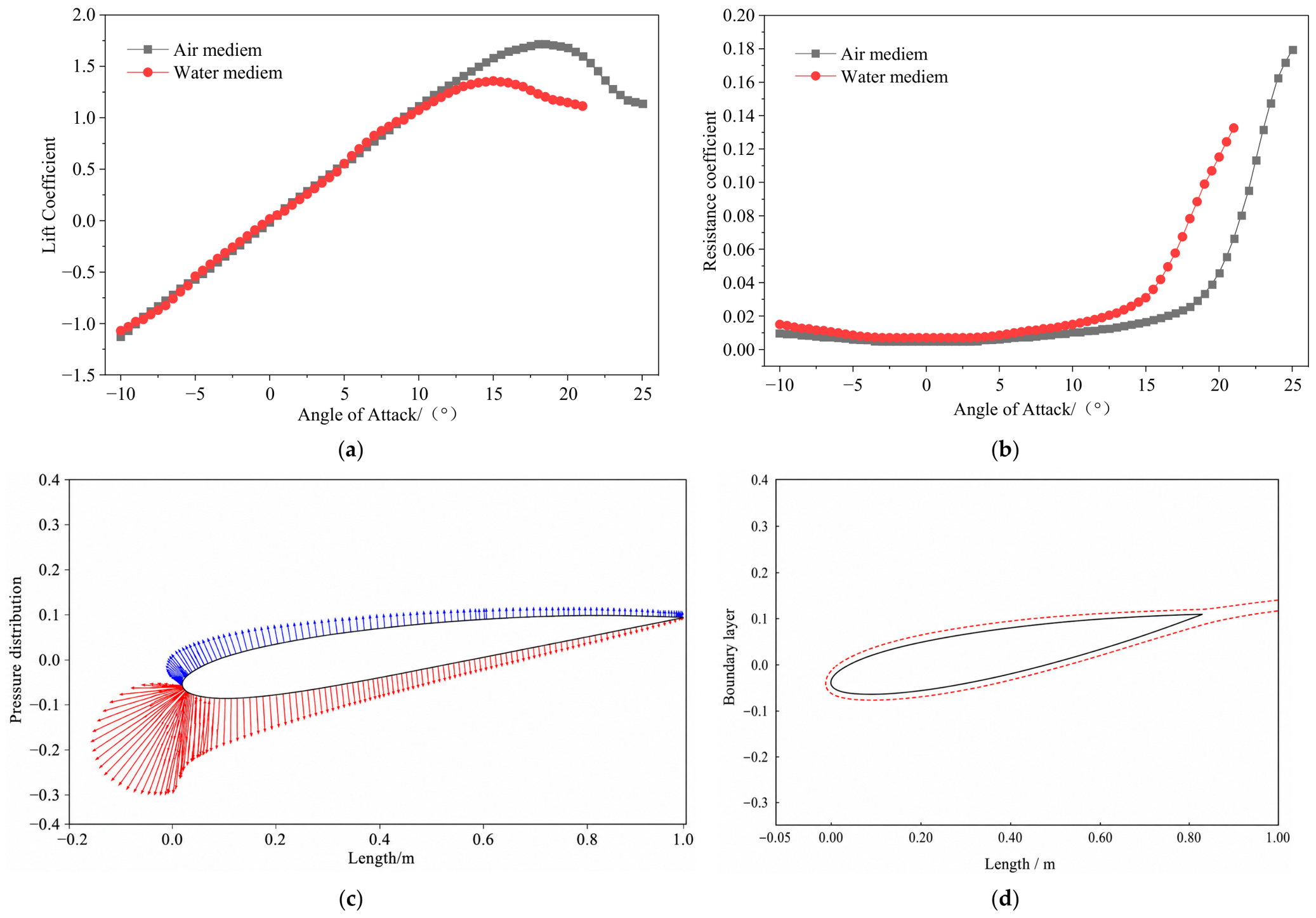
The baseline propeller employs a three-bladed configuration with NACA0012 blade sections and an initial outer diameter of 250 mm. To accommodate the hub connection and three-dimensional geometric modeling, each blade is shifted radially inward by 9 mm, resulting in a final analysis diameter of 232 mm. Representative lift and drag characteristics and surface-pressure distributions of the NACA0012 airfoil in air and water are presented in Figure 2.
The design space was screened in two stages. In the first stage, the global chord scaling factor and blade pitch angle were varied to identify promising candidates, whereas the spanwise chord-taper factor was refined for the shortlisted designs in the second stage. A composite metric was constructed from the normalized propulsive efficiency, thrust coefficient, and power coefficient in air and water. Greater weight was assigned to water operation, and a penalty term was introduced to prevent the selection of designs exhibiting strongly unbalanced cross-medium performance. Models A2, A3, and B3 advanced from the first-stage screening, with A2 achieving the highest composite score of 0.69086. The subsequent refinement identified A3 t1 as the highest-ranked design, with a score of 0.58656. Considering its air- and water-side performance together with geometric continuity, A3 t1 was selected as the baseline configuration for subsequent three-dimensional CFD and one-way fluid–structure interaction analyses. Its design parameters were Scale Chord = 0.80, Change Blade Angle = +2°, and Taper Chord = 1.00.

2.2. Flow Field and One-Way Fluid–Structure Coupling Model

Both air and water were modeled as incompressible continuous fluids. For the air start condition, the tip Mach number is reported to be approximately 0.107, which is below the conventional compressibility threshold for low-speed treatment. The governing continuity and momentum equations were solved using a finite volume CFD framework, and the SST k - ω turbulence model was adopted because of its established suitability for near-wall flows, adverse pressure gradients, and separation-prone rotating blade applications.
The computational domain comprised an inner rotating region and an outer stationary region. The blade and hub surfaces were prescribed as no-slip walls. For the air start and water start cases, the inlet velocity was set to zero, whereas a uniform axial inflow velocity of 5 m/s was imposed for the water inflow case to represent a comparatively demanding hydrodynamic loading condition. A pressure-outlet boundary condition was applied at the domain exit. The blade surface pressure field predicted by CFD was subsequently mapped onto the finite element model, together with the centrifugal load corresponding to the rotational speed of each operating condition. The structural model employed 6063-T5 aluminum alloy, with a density of 2.70 × 10³ kg/m3, Young’s modulus of 68.9 GPa, Poisson’s ratio of 0.33, and a yield strength of 145 MPa.
The fluid and structural domains were derived from a common geometric model to minimize load-mapping errors associated with mismatched interface boundaries. The CFD-predicted pressure field varied spatially in both the radial and chordwise directions, with pronounced gradients near the blade root transition. This non-uniform pressure distribution was subsequently mapped onto the structural model and combined with the corresponding centrifugal loading, thereby providing a more realistic representation of the structural response than uniform or simplified loading assumptions.
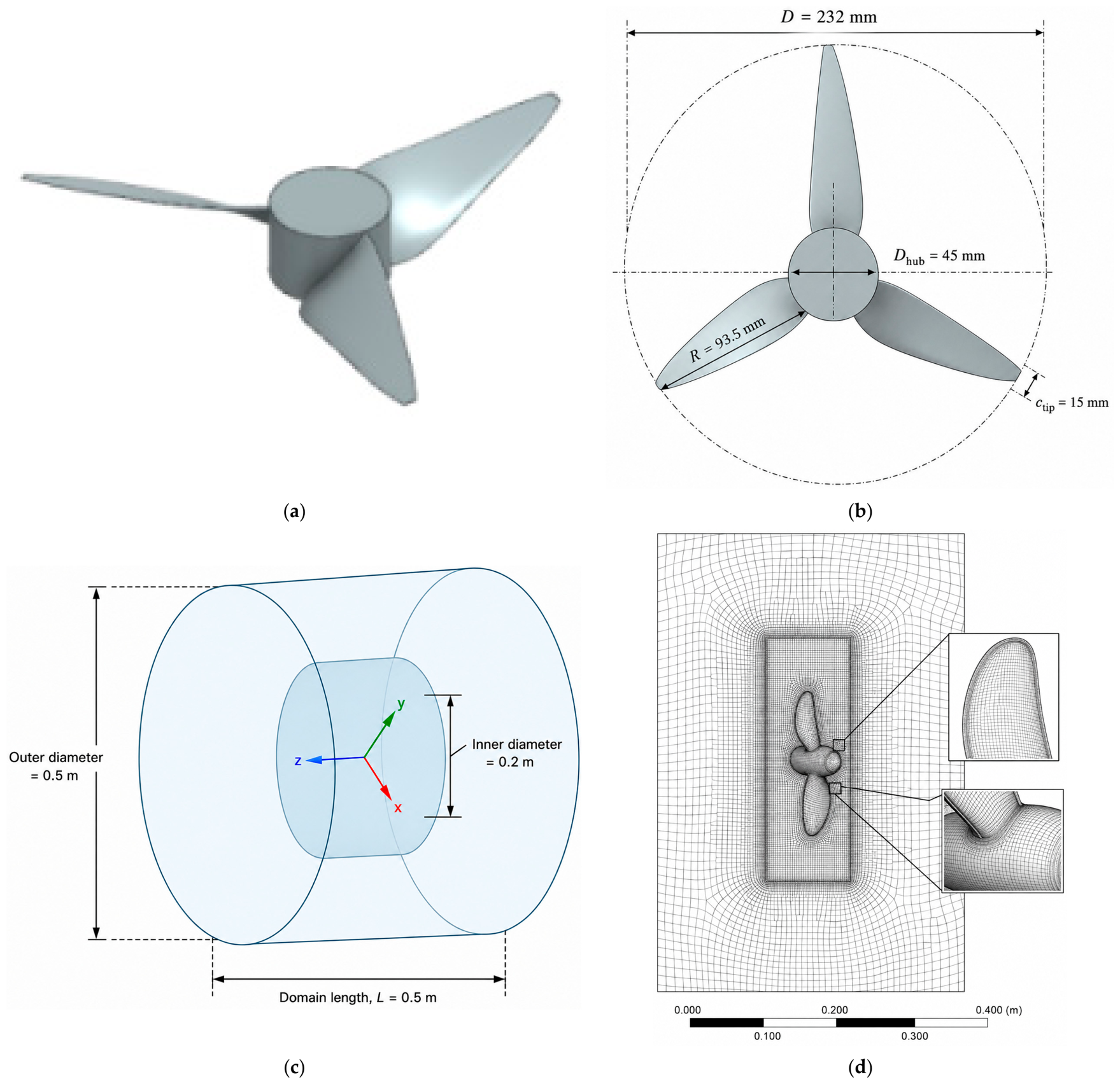
One-way fluid–structure coupling was adopted because the present study focuses on steady-state strength assessment across multiple operating conditions and local structural optimization, rather than on transient bidirectional interactions. This approach enables efficient identification of critical loading conditions and stress concentration regions. Nevertheless, it neglects the feedback of structural deformation on the flow field, may introduce interpolation errors during pressure transfer, and cannot capture transient hydroelastic effects. The operating conditions used in the CFD and structural analyses are summarized in Table 3. The baseline cross-medium propeller geometry, computational domain, and local mesh refinement are shown in Figure 3.

2.3. Operating Conditions and Mesh Independence Verification

Three operating conditions were considered: air start (V = 0 m/s, n = 3000 r/min, ρ = 1.225 kg/m3); water start (V = 0 m/s, n = 500 r/min, ρ = 1000 kg/m3); and water inflow (V = 5 m/s, n = 500 r/min, ρ = 1000 kg/m3). The mesh independence study was performed under the water inflow condition because this case combines high density with incoming flow and therefore yields the most demanding pressure-gradient distribution. The source manuscript reports that the relative difference between the medium and fine meshes is 0.2414% for area-weighted mean pressure and 0.0863% for peak pressure; accordingly, the fine mesh was selected for subsequent calculations.
A fluid domain was constructed around the selected impeller, with local mesh refinement applied to the blade surfaces, leading and trailing edges, blade root transition, blade tip, and rotating–stationary interface. These regions were refined to resolve steep velocity and pressure gradients and to improve the accuracy of the pressure loads subsequently transferred to the structural model. Mesh convergence was assessed under the water inflow condition, which represented the most demanding hydrodynamic case among the three operating conditions.
To assess the near-wall mesh resolution, the dimensionless wall distance y+ was evaluated on the blade and hub surfaces. The area-averaged y+ values were 0.42, 0.76, and 0.95 for the air start, water start, and water inflow conditions, respectively, while the corresponding maximum values were 1.35, 1.82, and 2.37. More than 95% of the blade surface exhibited y+ < 1, and the local maximum remained below 3. Therefore, the near-wall mesh adequately resolved the viscous sublayer and was suitable for the SST k − ω turbulence model.
Coarse, medium, and fine meshes were evaluated using the area-weighted mean and maximum static pressures on the blade surfaces. As reported in Table 4, the relative differences between the medium and fine meshes were only 0.2414% and 0.0863% for the mean and maximum static pressures, respectively, indicating that the pressure predictions were essentially mesh-converged. The fine mesh was therefore adopted for all subsequent CFD simulations to ensure consistent pressure load mapping and reliable comparisons among the operating conditions.
The differences in the blade surface pressure metrics between the medium and fine meshes were below 1%, indicating that the pressure solution was effectively mesh-converged. Because local pressure peaks may influence load transfer accuracy and the resulting structural response, the fine mesh was adopted for all subsequent simulations to minimize mesh-induced uncertainty in the mapped pressure loads.
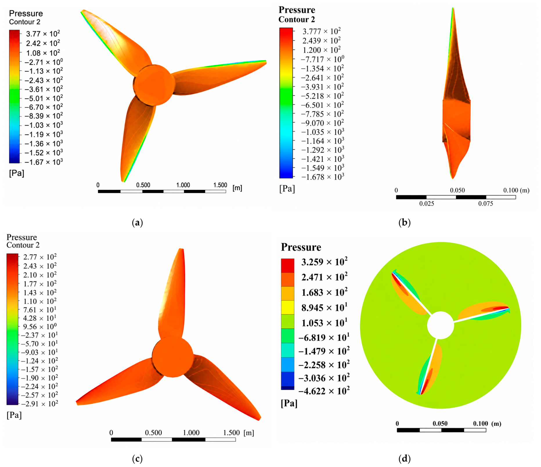
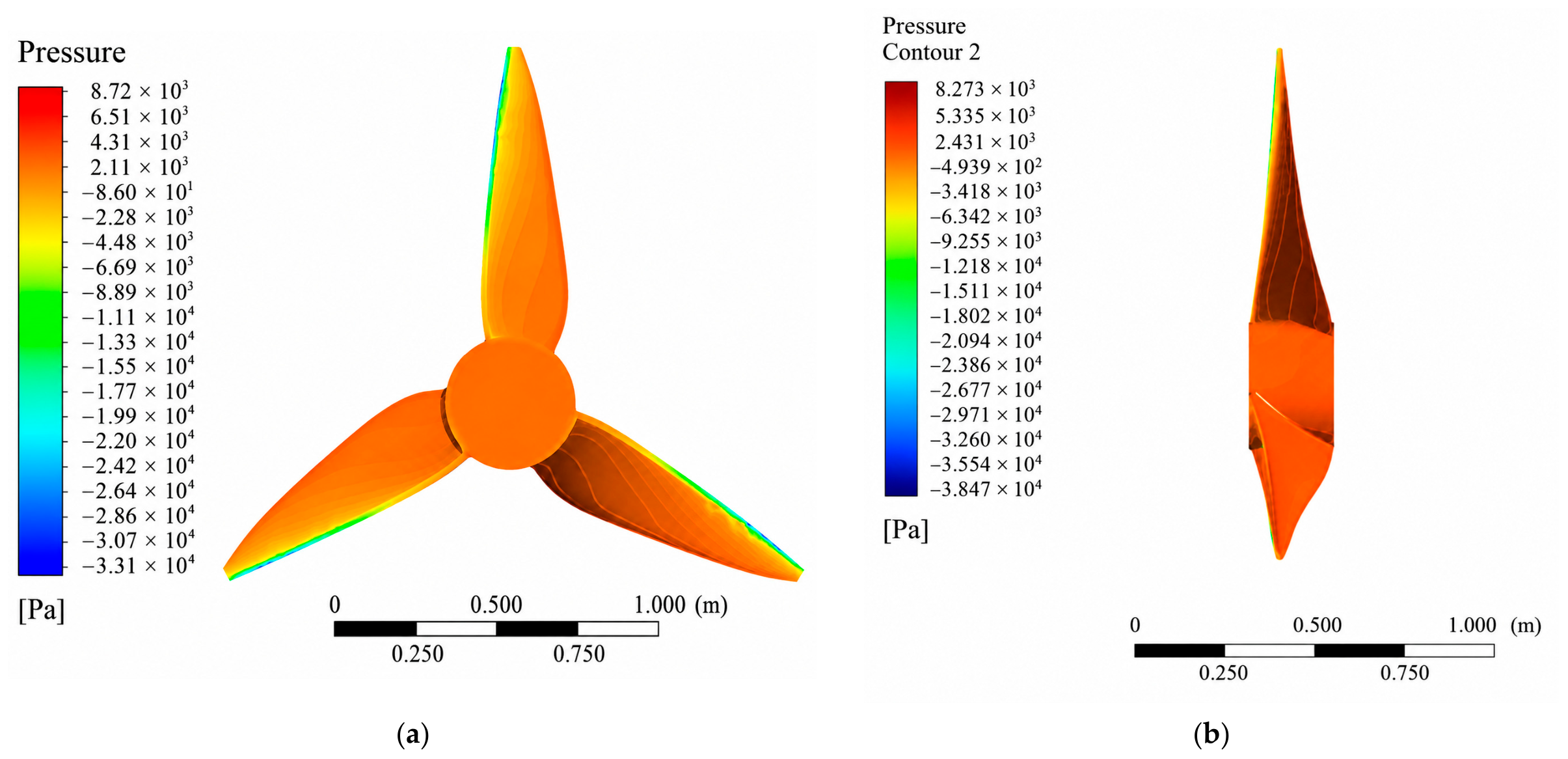
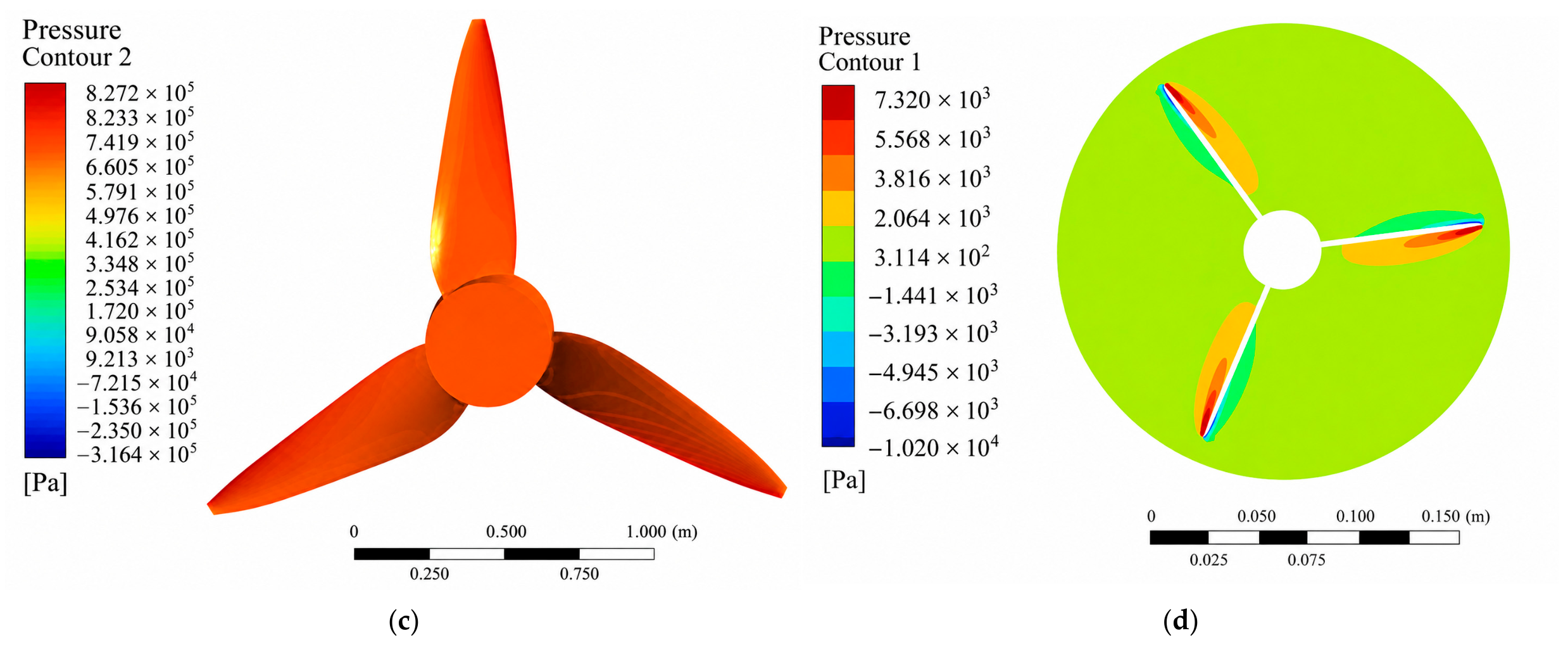
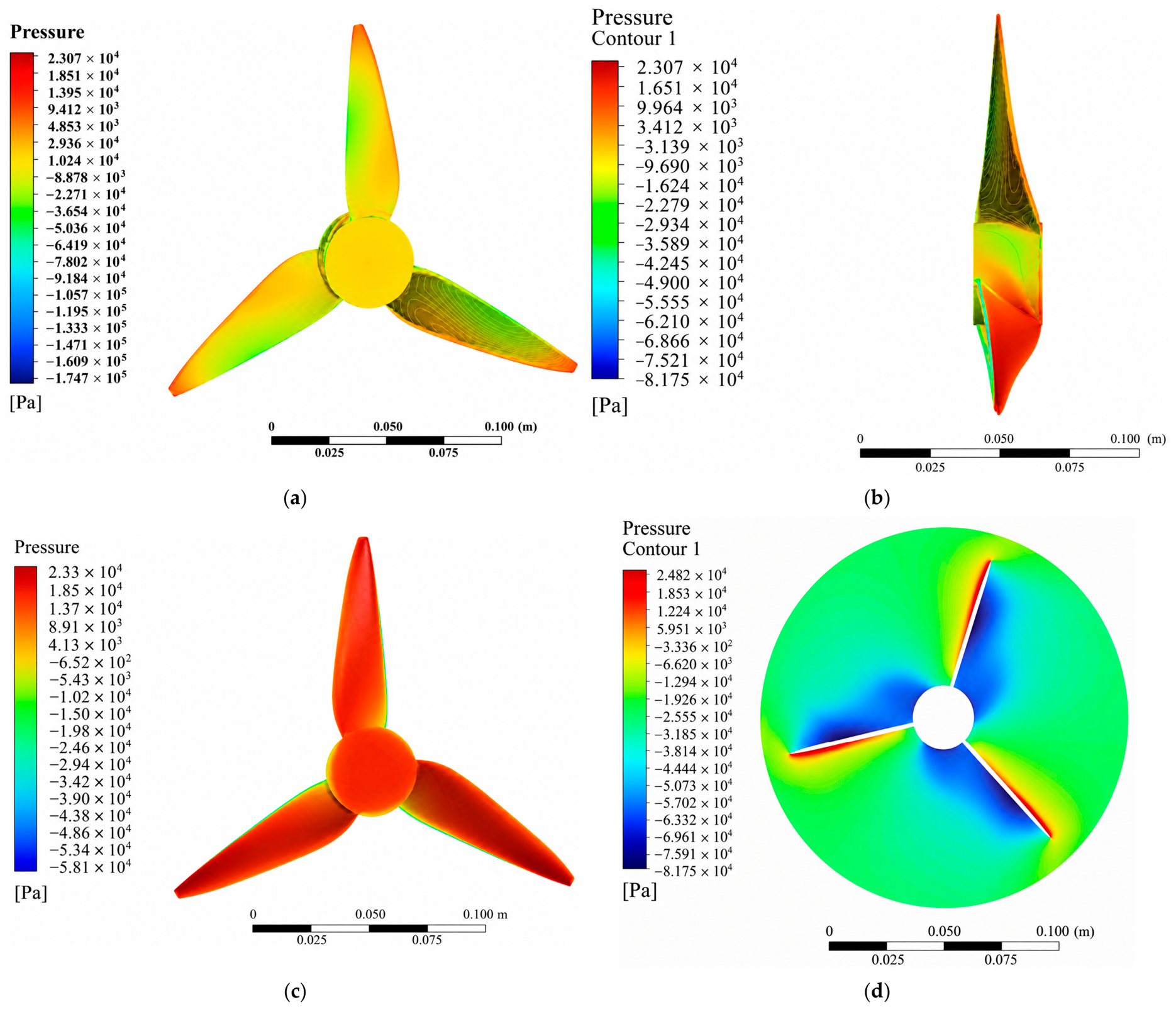
Figure 4, Figure 5 and Figure 6 present the CFD-predicted pressure distributions on the blade surface under the air-start, water-start, and water-inflow conditions, respectively. Higher pressures are observed near the leading edge and blade root, whereas lower pressures appear on the suction side and trailing edge. The pronounced pressure gradient at the root transition directly contributes to the stress concentration identified in the structural analysis.

3. Results and Discussion

3.1. Structural Response Analysis

The CFD-derived pressure field was mapped onto the corresponding blade surfaces of the finite element model. A fixed support was imposed at the hub–shaft interface to represent the mechanical constraint provided by the shafting system. Structural performance was evaluated in terms of the maximum von Mises stress and total deformation, while the location of the peak stress was used to identify the critical structural region.
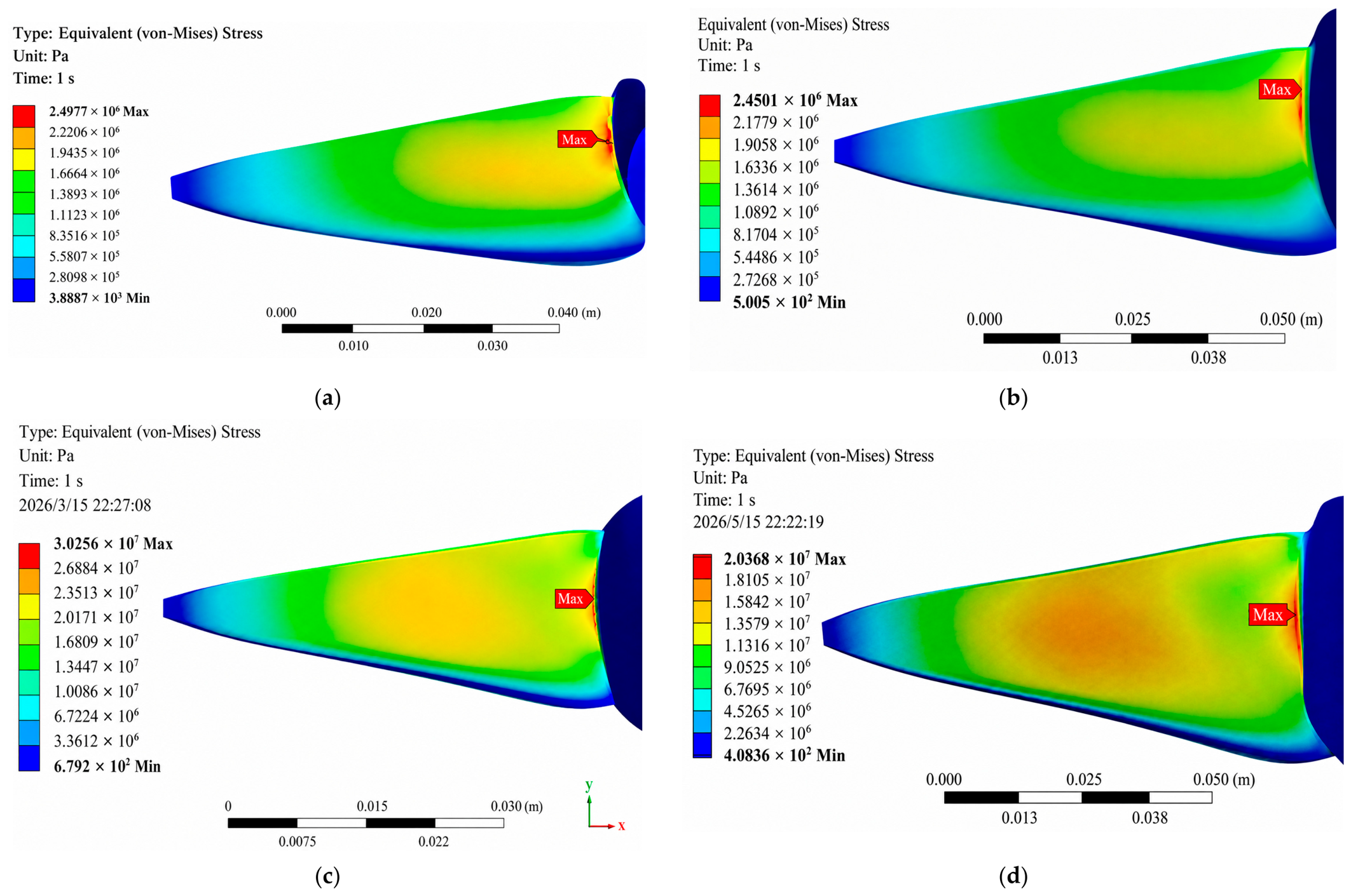
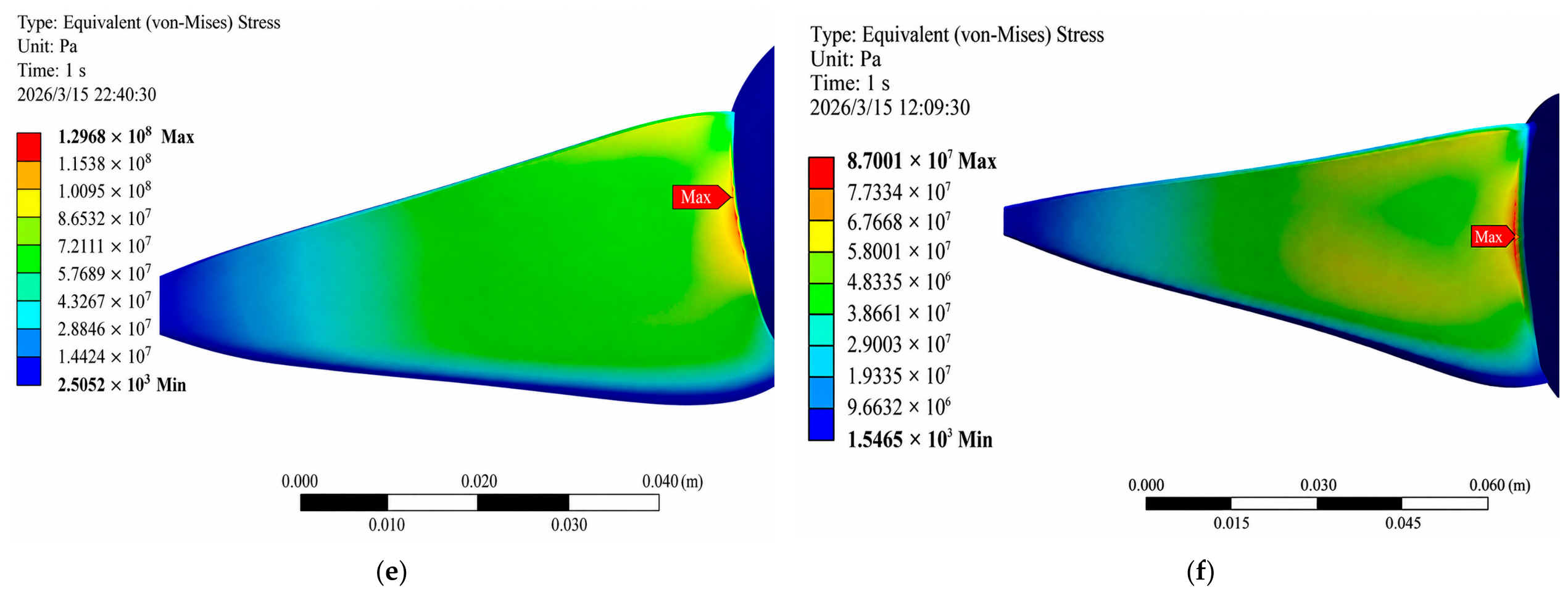
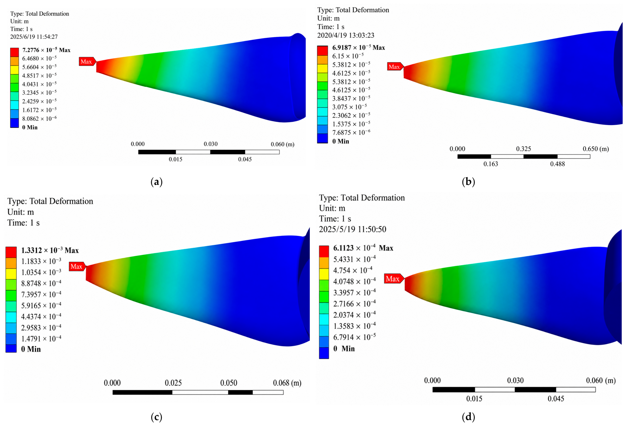
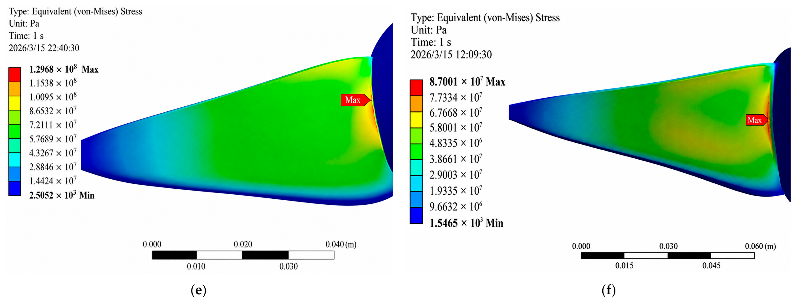
As summarized in Table 5, the air start condition exhibited the lowest structural response because of the relatively low fluid density and pressure loading. The maximum von Mises stress and total deformation were 2.4977 MPa and 0.073 mm, respectively. Under the water start condition, these values increased to 30.256 MPa and 1.133 mm, whereas the water inflow condition produced the highest von Mises stress of 129.8 MPa and a maximum deformation of 5.378 mm. In all three cases, the peak stress was consistently concentrated at the blade root transition, identifying this region as the principal load transfer path and the critical structural location.
Although the water start condition produced a larger maximum deformation than the water inflow condition, deformation and von Mises stress reflect different aspects of the structural response. Total deformation characterizes the global displacement of the impeller, whereas von Mises stress is more sensitive to localized loading and geometric stress concentration. Because the water inflow condition generated the highest equivalent stress and the most pronounced stress concentration at the blade root, it was selected as the critical loading condition for subsequent structural optimization.
The comparison across the three operating conditions indicates that the structural response does not scale monotonically with rotational speed, but is governed by the combined effects of fluid density, rotational speed, and axial inflow. Despite the highest rotational speed, the air start condition produces only a low stress level because of the relatively low density and pressure loading of air. In contrast, the substantially higher density of water increases the hydrodynamic load and overall deformation under the water start condition. With an additional axial inflow, the water inflow condition further intensifies the local pressure loading near the blade root, resulting in the highest von Mises stress among the three cases.
The stress contours reveal that the peak stress is consistently localized at the blade root transition rather than at the blade tip or mid-span. Hydrodynamic loads acting on the blade surfaces are transmitted through the blade to the hub, causing the root region to sustain substantial bending loads. The combination of this load transfer mechanism and the geometric discontinuity at the blade–hub junction promotes localized stress concentration. Therefore, structural optimization should primarily improve the geometric continuity and local load-bearing capacity of the blade root, rather than modifying the entire blade geometry. Similar propeller fluid–structure interaction studies have also identified the blade root region as a critical location for stress concentration.
Under the critical water inflow condition, the maximum von Mises stress of the original configuration reaches 129.8 MPa, corresponding to approximately 89.5% of the nominal yield strength of 6063-T5 aluminum alloy (145 MPa). Although the predicted stress remains below the yield limit, the resulting static strength margin is limited. Numerical uncertainty, manufacturing tolerances, material property variability, and operational disturbances may further reduce this margin. Consequently, targeted local optimization of the blade root transition is required to reduce the peak stress and enhance structural reliability during cross-medium operation.

3.2. Structural Optimization and Verification

3.2.1. Optimization Strategy

The optimization aimed to minimize the maximum von Mises stress while maintaining the maximum total deformation within an acceptable range. The stress contours identified the blade root–hub junction as the critical region; therefore, a 2 mm fillet was initially introduced at the blade root transition to improve geometric continuity. This local modification reduced the peak von Mises stress under both water start and water inflow conditions, while the stress under the air start condition remained comparatively low.
Further optimization considered three categories of design variables: airfoil profile, blade-setting angle, and blade root reinforcement. The candidate airfoils were NACA0012, NACA2412, and NACA0020, and the blade-setting angles were −2°, 0°, and +2°. Blade root reinforcement was parameterized using different combinations of the taper chord and chord scale factors. All parametric comparisons were conducted under the critical water inflow condition.
The blade root fillet mitigated the abrupt geometric transition at the blade–hub junction and promoted smoother load transfer. In the original configuration, the combined hydrodynamic-pressure and centrifugal loads generated a localized stress peak at this discontinuity. Introducing the 2 mm fillet produced a smoother curvature transition and consequently reduced the stress concentration under the two water-medium conditions. The effectiveness of improving root transition geometry is consistent with previous propeller studies identifying the blade root as a critical stress concentration region.
Variations in airfoil profile and blade-setting angle primarily affected the structural response by redistributing the hydrodynamic loads. Changing the airfoil altered its thickness, camber, and surface-pressure distribution, whereas adjusting the blade angle modified the effective angle of attack and the pressure difference across the blade. The results demonstrate that neither a thicker airfoil nor a larger blade angle necessarily reduces the peak stress, because the resulting load redistribution may create new stress concentrations near the blade root or blade edges.
Blade root reinforcement directly increased the load-bearing capacity of the critical region through coordinated adjustment of the taper chord and chord scale factors. Compared with global modifications to the airfoil profile or blade angle, this localized strategy produced less alteration to the overall blade geometry. Among the evaluated configurations, the Taper 0.90/Scale 1.05 scheme yielded the lowest peak stress under the water inflow condition. This result indicates that a moderate increase in the blade root load-bearing section, combined with controlled spanwise tapering, can improve structural safety while limiting changes to the baseline propulsion geometry. Fluid–structure-interaction-based propeller optimization studies similarly emphasize balancing structural strength with hydrodynamic performance through carefully selected geometric parameters.

3.2.2. Final Optimized Model

The final optimized configuration employs the NACA0012 airfoil with a blade angle of 0°. The blade root region is locally reinforced by setting the Taper Chord and Scale Chord parameters to 0.90 and 1.05, respectively, together with the introduction of a 2 mm blade root fillet. This design enhances the load-bearing capacity of the blade root while largely preserving the geometric and operational characteristics of the baseline impeller.
As summarized in Table 6 and Table 7, the baseline and optimized models exhibit substantially different structural responses under the three operating conditions. Under the air start condition, the maximum von Mises stress decreases slightly from 2.4977 to 2.450 MPa, corresponding to a reduction of 1.91%, whereas the maximum total deformation decreases from 0.073 to 0.069 mm, representing a reduction of 5.48%. Under the water start condition, the maximum von Mises stress and total deformation are reduced by 32.68% and 78.23%, respectively. Under the water inflow condition, the maximum von Mises stress decreases from 129.8 to 87.0 MPa, corresponding to a reduction of 32.97%, while the maximum total deformation decreases from 5.378 to 3.669 mm, representing a reduction of 31.77%. These results demonstrate that the proposed optimization is particularly effective in improving structural performance under high-load, water-medium operating conditions.
The comparative stress and deformation distributions further indicate that the effects of optimization are concentrated primarily under the water start and water inflow conditions. Under the air start condition, both stress and deformation are inherently low; consequently, only limited absolute improvements are obtained. In contrast, the substantially higher hydrodynamic loads generated during water start and water inflow operation intensify stress concentration and deformation in the blade root region. Under these conditions, the combined effects of local chord reinforcement and the smooth fillet transition become more pronounced. In particular, reducing the maximum von Mises stress to 87.0 MPa under the water inflow condition appreciably increases the static strength margin of the impeller.
The final configuration was not selected solely on the basis of the minimum stress obtained from an individual parameter combination. Instead, structural performance, geometric continuity, hydrodynamic compatibility, and engineering feasibility were considered simultaneously. Although further enlargement of the blade root region could potentially reduce the local peak stress, excessive geometric modification would alter the spanwise blade profile and flow field characteristics and could also increase the impeller mass, rotational inertia, and power consumption. The selected configuration therefore represents a balanced compromise; it substantially suppresses peak stress and deformation under critical water-medium conditions while avoiding excessive modification of the baseline blade geometry. Overall, the optimized impeller exhibits improved structural reliability, satisfactory multi-condition adaptability, and practical engineering feasibility. The von Mises stress and total deformation contours for the baseline and optimized models are shown in Figure 7 and Figure 8, respectively, confirming the effectiveness of the proposed optimization.

3.2.3. Engineering Implications of Multi-Condition Results

The structural responses under the three operating conditions indicate that the mechanical loading of the impeller cannot be interpreted as a simple monotonic function of rotational speed. Although the air start condition involves the highest rotational speed, the low density of air results in relatively weak aerodynamic loading and, consequently, limited structural deformation. By contrast, the substantially higher density of water produces greater hydrodynamic loads during water start-up, leading to a pronounced increase in total deformation. With the additional axial inflow, the water inflow condition generates more complex and nonuniform pressure distributions, particularly near the blade root, and therefore represents the most critical operating condition for structural strength design.
These results further demonstrate that the maximum von Mises stress and maximum total deformation are governed by different aspects of the structural response. The former is primarily associated with localized load transfer, geometric discontinuities, and stress concentration, whereas the latter reflects the overall stiffness and global deformation of the impeller. Under cross-medium operating conditions, the introduction of external inflow may therefore spatially separate the peak stress region from the location of maximum displacement. Accordingly, the structural optimization of cross-medium impellers should incorporate the spatial distributions of both stress and deformation rather than relying exclusively on a single global maximum.

3.2.4. Error Sources and Method Applicability

The one-way fluid–structure interaction approach offers a favorable balance between computational efficiency and physical interpretability, making it suitable for preliminary engineering design and parametric screening. To minimize the uncertainties associated with neglecting deformation-induced flow field feedback, load transfer interpolation, and steady-state CFD assumptions, a consistent geometric model, local mesh refinement, and rigorous mesh independence assessments were employed. Nevertheless, the present approach is primarily intended for initial design evaluation. Prior to prototype fabrication and engineering implementation, further validation should incorporate transient fluid loading, fatigue performance, and manufacturing tolerances and constraints.

3.2.5. Generality of the Optimization Strategy

The localized optimization of the blade root transition proved more effective and computationally efficient than global modifications to the airfoil profile or blade angle. By directly improving the load transfer path and alleviating geometric discontinuities, this strategy enhances structural integrity while largely preserving the hydrodynamic characteristics of the baseline impeller. The integrated workflow—comprising BEMT-based preliminary screening, CFD load extraction, and finite element identification of critical regions—provides an efficient and transferable framework for the structural optimization of similar cross-medium propulsion systems.

4. Conclusions and Countermeasures

This study developed an integrated workflow combining BEMT screening, CFD load extraction, and one-way fluid–structure coupling to evaluate the structural performance of a cross-medium propeller under three representative operating conditions: air start, water start, and water inflow. The results demonstrate that the structural response is highly sensitive to the medium and inflow condition, and that the water inflow case constitutes the critical structural design scenario.
Across all evaluated conditions, the blade root transition was consistently identified as the principal load transfer path and the dominant stress concentration region. This finding provided a clear optimization target for local geometric modification.
A localized optimization strategy involving a 2 mm fillet and blade root reinforcement proved effective. Under the critical water inflow condition, the optimized configuration reduced the maximum von Mises stress from 129.8 MPa to 87.0 MPa and the maximum total deformation from 5.378 mm to 3.669 mm. The optimization also improved the structural response under the other operating conditions.
The proposed procedure is suitable for the preliminary engineering design of cross-medium propellers because it connects fast performance screening with higher-fidelity structural checking and targeted local redesign. Future work should incorporate experimental validation, transient or two-way fluid–structure interaction, fatigue assessment, and simultaneous optimization of structural safety and propulsive performance.

Author Contributions

Conceptualization, T.Z. and G.Z.; methodology, T.Z. and Z.W.; software, Z.W.; validation, M.Z. and G.Z.; formal analysis, T.Z.; investigation, T.Z.; resources, G.Z.; data curation, Z.W.; writing—original draft preparation, T.Z.; writing—review and editing, Z.W., M.Z. and G.Z.; visualization, Z.W.; supervision, G.Z.; project administration, T.Z.; funding acquisition, G.Z. All authors have read and agreed to the published version of the manuscript.

Funding

The Project of the Joint Research Institute for Clean Energy Technology Innovation and Achievement Transformation, Qinghai University (No. LHYJY-04-05).

Institutional Review Board Statement

Not applicable.

Informed Consent Statement

Not applicable.

Data Availability Statement

The data that support the findings of this study are contained within the article.

Conflicts of Interest

Author Guobin Zhang was employed by HohhotInner Mongolia Power Group Alxa Power Supply Company. The remaining authors declare that the research was conducted in the absence of any commercial or financial relationships that could be construed as a potential conflict of interest.

References

  1. Yao, G.; Li, Y.; Zhang, H.; Jiang, Y.; Wang, T.; Sun, F.; Yang, X. Review of hybrid aquatic-aerial vehicle (HAAV): Classifications, current status, applications, challenges and technology perspectives. Prog. Aerosp. Sci. 2023, 139, 100902. [Google Scholar] [CrossRef] [Scilit]
  2. Li, L.; Wang, S.; Zhang, Y.; Song, S.; Wang, C.; Tan, S.; Zhao, W.; Wang, G.; Sun, W.; Yang, F.; et al. Aerial-aquatic robots capable of crossing the air-water boundary and hitchhiking on surfaces. Sci. Robot. 2022, 7, eabm6695. [Google Scholar] [CrossRef] [Scilit] [PubMed]
  3. Qin, K.; Tang, W.; Zhong, Y.; Liu, Y.; Xu, H.; Zhu, P.; Yan, D.; Yang, H.; Zou, J. An Aerial–Aquatic Robot with Tunable Tilting Motors Capable of Multimode Motion. Adv. Intell. Syst. 2023, 5, 202300193. [Google Scholar] [CrossRef] [Scilit]
  4. Jin, Y.; Bi, Y.; Lyu, C.; Bai, Y.; Zeng, Z.; Lian, L. Nezha-IV: A hybrid aerial underwater vehicle in real ocean environments. J. Field Robot. 2024, 41, 420–442. [Google Scholar] [CrossRef] [Scilit]
  5. Pinheiro, P.M.; Neto, A.A.; Grando, R.B.; da Silva, C.B.; Aoki, V.M.; Cardoso, D.S.; Horn, A.C.; Drews, P.L.J. Trajectory Planning for Hybrid Unmanned Aerial Underwater Vehicles with Smooth Media Transition. J. Intell. Robot. Syst. 2022, 104, 1–16. [Google Scholar] [CrossRef] [Scilit]
  6. Li, J.; Jin, Y.; Hu, R.; Bai, Y.; Lu, D.; Zeng, Z.; Lian, L. Trajectory Tracking Control of Fixed-Wing Hybrid Aerial Underwater Vehicle Subject to Wind and Wave Disturbances. J. Intell. Robot. Syst. 2024, 110, 92. [Google Scholar] [CrossRef] [Scilit]
  7. Lyu, C.; Lu, D.; Xiong, C.; Hu, R.; Jin, Y.; Wang, J.; Zeng, Z.; Lian, L. Toward a gliding hybrid aerial underwater vehicle: Design, fabrication, and experiments. J. Field Robot. 2022, 39, 543–556. [Google Scholar] [CrossRef] [Scilit]
  8. Liu, K.; Liu, Y.; Lin, H.; Xiao, J.; Peng, H.; Lu, X.; Lu, H. Research of Trans-Medium Strategy for Unmanned Aerial-Undersea Vehicles. J. Unmanned Undersea Syst. 2024, 32, 396–410. [Google Scholar]
  9. Liu, S.; Du, C.; Han, Y.; Zhang, Y.; Lin, W.; Cai, Y.; Wang, T. Research on Hydrodynamics of Trans-Media Vehicles Considering Underwater Time-Varying Attitudes. J. Mar. Sci. Eng. 2024, 12, 1338. [Google Scholar] [CrossRef] [Scilit]
  10. Qiao, F.; Sun, Y.; Zhu, D.; Fang, M.; Zhang, F.; Tao, R.; Xiao, R. Analysis of Stress–Strain Characteristics and Signal Coherence of Low-Specific-Speed Impeller Based on Fluid–Structure Interaction. J. Mar. Sci. Eng. 2024, 12, 2. [Google Scholar] [CrossRef] [Scilit]
  11. Han, S.; Wang, P.; Jin, Z.; An, X.; Xia, H. Structural design of the composite blades for a marine ducted propeller based on a two-way fluid-structure interaction method. Ocean Eng. 2022, 259, 111872. [Google Scholar] [CrossRef] [Scilit]
  12. Guan, G.; Zhang, X.; Wang, P.; Yang, Q. Multi-objective optimization design method of marine propeller based on fluid-structure interaction. Ocean Eng. 2022, 252, 111222. [Google Scholar] [CrossRef] [Scilit]
  13. Krishna, V.R.; Sanaka, S.P.; Pardhasaradhi, N.; Rao, B.R. Hydro-elastic computational analysis of a marine propeller using two-way fluid structure interaction. J. Ocean Eng. Sci. 2022, 7, 280–291. [Google Scholar] [CrossRef] [Scilit]
  14. An, X.; Wang, P.; Ye, M.; He, R.; Li, C.; Lessard, L. Tip clearance influence on hydrodynamic performance and pressure fluctuation of a composite ducted propeller using a two-way FSI method. Ocean Eng. 2023, 282, 114698. [Google Scholar] [CrossRef] [Scilit]
  15. Li, J.; Qu, Y.; Zhang, Z.; Xie, D.; Hua, H.; Wu, J. Fluid-structure interaction analysis of the propeller-shafting system in a non-uniform wake. Ocean Eng. 2023, 289, 116189. [Google Scholar] [CrossRef] [Scilit]
  16. Kim, S.; Shin, S. Improved unsteady fluid–structure interaction analysis using the dynamic mode decomposition on a composite marine propeller. Ocean Eng. 2025, 319, 120255. [Google Scholar] [CrossRef] [Scilit]
  17. Choi, Y.-S.; Hong, S.-Y.; Song, J.-H. Investigation of the effect of adaptive characteristics on non-cavitating noise for flexible propeller in non-uniform flow via the fluid-structure interaction model. Int. J. Nav. Archit. Ocean Eng. 2023, 15, 100541. [Google Scholar] [CrossRef] [Scilit]
  18. Kumar, A.; Rajagopalan, V. Influence of geometric variations and stacking sequencing of a composite marine propeller. Ocean Eng. 2024, 312, 119106. [Google Scholar] [CrossRef] [Scilit]
  19. Rokvam, S.Ø.; Vedvik, N.P.; Mark, L.; Rømcke, E.; Ølnes, J.S.; Savio, L.; Echermeyer, A. Experimental Verification of the Elastic Response in a Numeric Model of a Composite Propeller Blade with Bend Twist Deformation. Polymers 2021, 13, 3766. [Google Scholar] [CrossRef] [Scilit] [PubMed]
  20. Tavakoli, S.; Singh, M.; Hosseinzadeh, S.; Hu, Z.; Shao, Y.; Wang, S.; Huang, L.; Grammatikopoulos, A.; Li, Y.P.; Khojasteh, D.; et al. A review of flexible fluid-structure interactions in the ocean: Progress, challenges, and future directions. Ocean Eng. 2025, 342, 122545. [Google Scholar] [CrossRef] [Scilit]
  21. Faris, A.F.A.; Basri, A.A.; Basri, E.I.; Gires, E.; Sultan, M.T.H.; Ahmad, K.A. Propeller Design and Performance Evaluation by Using Computational Fluid Dynamics (CFD): A Review. J. Aeronaut. Astronaut. Aviat. 2021, 53, 263–274. [Google Scholar]
  22. Liu, X.; Zhao, D.; Oo, N.L. Comparison studies on aerodynamic performances of a rotating propeller for small-size UAVs. Aerosp. Sci. Technol. 2023, 133, 108148. [Google Scholar] [CrossRef] [Scilit]
  23. Gao, Z.; Shao, X.; Zeng, L.; Liu, L.; Li, J. Hybrid Aerodynamic Optimization of a Propeller Based on the Reformulated Blade Element Momentum Theory. J. Aerosp. Eng. 2024, 37, 04023112. [Google Scholar] [CrossRef] [Scilit]
  24. Luo, L.; Chen, Z.; Zheng, X.; Wang, C.; Lu, K. Optimization design and dynamic performance calculation of hybrid aerial-aquatic propeller. Comp. Simulat. 2023, 40, 5–10. [Google Scholar]
  25. Wu, X.; Zuo, Z.; Ma, L.; Zhang, W. Multi-fidelity neural network-based aerodynamic optimization framework for propeller design in electric aircraft. Aerosp. Sci. Technol. 2024, 146, 108963. [Google Scholar] [CrossRef] [Scilit]
  26. Razaghian, A.; Ebrahimi, A.; Zahedi, F.; Javanmardi, M.; Seif, M. Investigating the effect of geometric parameters on hydrodynamic and hydro-acoustic performances of submerged propellers. Appl. Ocean Res. 2021, 114, 102773. [Google Scholar] [CrossRef] [Scilit]
  27. Zhang, X.; Liu, Z.; Cao, L.; Wan, D. Tip Clearance Effect on The Tip Leakage Vortex Evolution and Wake Instability of a Ducted Propeller. J. Mar. Sci. Eng. 2022, 10, 1007. [Google Scholar] [CrossRef] [Scilit]
  28. Choi, Y.-S.; Hong, S.-Y.; Song, J.-H. Composite propeller design optimization for cavitation minimization using deep learning-based objective parameter prediction model. Ocean Eng. 2023, 287, 115760. [Google Scholar] [CrossRef] [Scilit]
  29. Zhang, D.D.; Zhang, J.; Liu, Y.; Wu, Q.; Huang, B.; Wang, G.Y. Numerical investigation on open-water performance and structural characteristics of composite propellers. J. Ship Mechan. 2023, 40, 173–184. [Google Scholar]
  30. Crona, M.; Dinger, S.; Samuelsson, P.; Strömfeldt, H.; Jonsson, I. Low-Speed Propeller for UAV Applications, from Design to Experimental Evaluation. In ICAS Proceedings, 2024. Available online: https://research.chalmers.se/publication/543830/file/543830_Fulltext.pdf (accessed on 12 August 2026).
  31. Portillo-Juan, A.; Saettone, S.; Andersen, P.; Ferrer, E. Hydro-acoustic optimization of propellers: A review of design methods. Appl. Ocean Res. 2024, 151, 104158. [Google Scholar] [CrossRef] [Scilit]
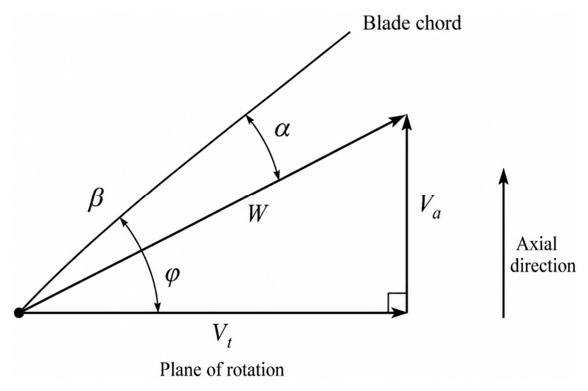
Figure 1. Velocity triangle of a blade element used in the BEMT formulation.
Fluids 11 00225 g001
Figure 2. Representative aerodynamic and hydrodynamic characteristics of the NACA0012 airfoil in air and water. (a) Lift coefficient curve. (b) Resistance coefficient curve. (c) Pressure distribution curve. (d) Boundary layer characteristic map.
Fluids 11 00225 g002
Figure 3. Baseline cross-medium propeller geometry, computational domain, and local mesh refinement. (a) Perspective view. (b) Front view. (c) Fluid domain. (d) Fluid domain mesh.
Fluids 11 00225 g003
Figure 4. Pressure distribution on the propeller surface and sectional plane under the air start condition. (a) Top view. (b) Side view. (c) Bottom view. (d) Sectional view.
Fluids 11 00225 g004
Figure 5. Pressure distribution on the propeller surface and sectional plane under the water start condition. (a) Top view. (b) Side view. (c) Bottom view. (d) Sectional view.
Fluids 11 00225 g005aFluids 11 00225 g005b
Figure 6. Pressure distribution on the propeller surface and sectional plane under the water inflow condition. (a) Top view. (b) Side view. (c) Bottom view. (d) Sectional view.
Fluids 11 00225 g006
Figure 7. Comparison of von Mises stress between the baseline and optimized models under the three operating conditions. (a) Air start, original model. (b) Air start, optimized model. (c) Water start, original model. (d) Water start, optimized model. (e) Water inflow, original model. (f) Water inflow, optimized model.
Fluids 11 00225 g007aFluids 11 00225 g007b
Figure 8. Comparison of total deformation between the baseline and optimized models under the three operating conditions. (a) Air start, original model. (b) Air start, optimized model. (c) Water start, original model. (d) Water start, optimized model. (e) Water inflow, original model. (f) Water inflow, optimized model.
Fluids 11 00225 g008aFluids 11 00225 g008b
Table 1. First-round BEMT screening results for candidate cross-medium propeller configurations.
RankModelScoreWater Side Score (Sw)Air Side Score (Sa)
1A20.690860.675010.72785
2A30.603960.560950.70430
3B30.557570.457800.79036
4C20.507230.489370.54889
5B10.466920.675700.25814
6C30.449210.350000.68069
7B20.447890.622330.27345
8A10.442750.623870.26163
9C10.360970.557250.16469
Table 2. Second-round BEMT refinement results for the shortlisted configurations.
RankModelScoreWater Side Score (Sw)Air Side Score (Sa)
1A3 t10.586560.473850.84955
2A3 t30.561350.554160.57812
3A3 t20.546180.515410.61798
4B3 t30.488610.484880.49732
5A2 t30.474010.589150.35888
6A2 t10.437100.622060.25214
7A2 t20.429310.678090.18053
8B3 t20.379970.432160.32778
9B3 t10.366340.350000.40447
Table 3. Operating conditions used in the CFD and structural analyses.
ConditionMediumV/(m/s)n/(r/min)ρ/(kg/m3)
Air startAir030001.225
Water startWater05001000
Water inflowWater55001000
Table 4. Mesh independence verification.
MeshNodes/ElementsPavg/PaPmax/PaRelative Error/%
Coarse mesh156,320/859,147−3881.2026,587.042.9233/0.3972
Medium mesh240,838/1,332,486−3780.0626,458.980.2414/0.0863
Fine mesh379,475/2,120,280−3770.9626,481.85
Table 5. Structural response of the baseline model under the three operating conditions.
ConditionMaximum von
Mises Stress/MPa
Maximum Total
Deformation/mm
Air start2.49770.073
Water start30.2561.133
Water inflow129.8005.378
Table 6. Effects of design variables on maximum von Mises stress under the critical water inflow condition.
VariableSchemeMaximum von Mises Stress/MPa
AirfoilNACA0012110.11
AirfoilNACA2412145.89
AirfoilNACA0020126.95
Blade angle−2°105.73
Blade angle110.11
Blade angle+2°120.36
Blade rootTaper 1.00/Scale 1.00110.11
Blade rootTaper 0.95/Scale 1.0391.96
Blade rootTaper 0.90/Scale 1.0587.00
Table 7. Comparison of the baseline and optimized models under the three operating conditions.
ConditionModelMaximum von Mises Stress/MPaMaximum Total
Deformation/mm
Air startOriginal model2.49770.073
Air startOptimized model2.4500.069
Water startOriginal model30.2561.330
Water startOptimized model20.3680.611
Water inflowOriginal model129.8005.378
Water inflowOptimized model87.0013.669
Disclaimer/Publisher’s Note: The statements, opinions and data contained in all publications are solely those of the individual author(s) and contributor(s) and not of MDPI and/or the editor(s). MDPI and/or the editor(s) disclaim responsibility for any injury to people or property resulting from any ideas, methods, instructions or products referred to in the content.