Article

Evaluation of Surface Roughness, Cutting Forces, and Tool Wear Under MQL Using Different Nano Cutting Oils in Milling Hastelloy C276 Superalloy

1
Department of Mechanical Engineering, Faculty of Mechanical, Thai Nguyen University of Technology, Thai Nguyen 250000, Vietnam
2
Mechanical Engineering Faculty, Thai Nguyen University of Technology, Thai Nguyen 250000, Vietnam
*
Author to whom correspondence should be addressed.
Fluids 2026, 11(5), 123; https://doi.org/10.3390/fluids11050123
Submission received: 31 March 2026 / Revised: 1 May 2026 / Accepted: 12 May 2026 / Published: 19 May 2026
(This article belongs to the Section Flow of Multi-Phase Fluids and Granular Materials)

Abstract

This paper presents a study on evaluating the effectiveness of nanofluid Minimum Quantity Lubrication (NF MQL) in machining Hastelloy C276 alloy—a difficult-to-cut material. The study compares NF MQL using different types of nanoparticles (Al2O3, MoS2, SiC, and GrP) with dry and pure MQL conditions in terms of surface roughness, cutting force components, and especially the variation of cutting forces over time. Experimental results indicate that the graphene-containing nanofluid MQL showed the most superior performance in terms of surface roughness Ra with 54.3% and 34% reduction, followed by MoS2 and Al2O3 nanofluid MQL conditions. Regarding the active cutting force Fa, Al2O3 nanofluid MQL achieves the largest reduction of about 18.4% and 22.1% when compared to dry and pure MQL, followed by GrP nanofluid MQL, MoS2 nanofluid MQL, and then SiC nanofluid MQL. Meanwhile, GrP nanofluid MQL shows the highest percentage of Fz reduction at about 13.4% and 26% when compared to the dry and pure MQL conditions, followed by MoS2 nanofluid MQL. Furthermore, the application of NF MQL also significantly improves tool life and extends about 36.4 ÷ 61.1% and 18.2 ÷ 50% compared to dry and pure MQL, respectively. Notably, through in-depth analysis of the variation of cutting forces, the study has elucidated the superior lubrication and cooling mechanism of the NF MQL method, confirming its potential application in machining advanced materials.

1. Introduction

Nickel-based superalloys are a group of high-performance metallic materials in which nickel acts as the primary element and is alloyed with elements such as Cr, Co, Mo, W, Al, Ti, or Nb to improve properties. Thanks to their unique microstructure consisting of a γ matrix phase (solid nickel solution) and a γ′ strengthening phase (Ni3(Al, Ti)), these alloys exhibit very high mechanical strength at high temperatures, excellent resistance to creep, oxidation, and corrosion [1]. Therefore, nickel-based superalloys are widely used in harsh working environments such as jet engine turbine blades, gas turbines in power plants, and equipment in the oil and gas, chemical, mechanical, and high-temperature industries [2]. Due to their many excellent properties, they are classified as difficult-to-machine materials. The difficulty in machining nickel-based superalloys stems from the combination of their superior mechanical and thermal properties. First, the high strength and hardness, especially at high temperatures, result in very high cutting forces during machining, causing rapid tool wear [3]. In addition, the strong strain hardening ability causes the surface material layer to become harder after each cut, making subsequent machining more difficult [4]. Nickel-based superalloys also have low thermal conductivity, meaning that heat generated in the cutting zone is not dissipated quickly but concentrates at the cutting tool, increasing temperature, causing wear, and reducing tool life [5]. Furthermore, this material tends to adhere to the cutting edge, causing built-up-edge (BUE) and reducing the quality of the machined surface [6]. The complex alloy composition with strengthening phases such as γ′ also contributes to increased resistance to deformation, making the cutting process more difficult [4]. Therefore, when machining nickel-based superalloys, the use of appropriate cutting tools, cutting parameters, and effective lubrication and cooling methods is crucial to ensuring quality and productivity [7,8].
Modi et al. [9] optimized the cutting parameters (cutting speed, feed rate, and cutting depth) to achieve the minimum values of cutting force, surface roughness, and tool wear in turning Hastelloy C276. The Taguchi method and RSM methodology were applied to design the experiments and find out the optimal values. Oschelski et al. [10] used a Box–Behnken experimental design to investigate the effects of cutting speed, cutting depth, and cooling lubrication conditions on the average surface roughness in turning Hastelloy® X. The experimental results indicated that cutting speed and depth of cut were the most influential while the cutting depth above 1.5× nose radius of the cutting tool resulted the higher values of surface roughness because of chatter vibration. The MQL condition brought out equivalent results to wet cutting, so it can be an alternative solution to reduce cutting oil consumption. Singh et al. [11] compared the effects of different cooling lubrication conditions (dry, wet, and MQL) on the turning performance of Hastelloy C276. Based on ANOVA analysis, the cutting depth and cooling condition have significant influences on surface roughness while cutting heat is strongly affected by cutting speed, followed by cooling environment and then the cutting depth. Furthermore, chip reduction coefficient is mainly influenced by feed rate. Wang et al. [12] developed a multiscale CPFE model to study subsurface generation in ultra-precision diamond milling of pure Nickel. The findings indicated a larger cutting depth stimulated the creation and accumulation of dislocations, leading to a thicker subsurface damage layer.
Sivalingam et al. [13] conducted a study on the turning performance of Hastelloy X by using a PVD Ti-Al-N coated insert. The experiments were conducted under dry, wet, and cryogenic conditions. The Moth-Flame Optimization (MFO) algorithm was used to identify the optimal set of turning parameters. The obtained results were validated by comparing it to other algorithms (Genetic Algorithm, Grass-Hooper Optimization (GHO), Grey-Wolf Optimization (GWO), and Particle Swarm Optimization (PSO). Besides, compared to dry and wet cutting, the cryogenic environment effectively reduced the cutting force and cutting temperature. Dhananchezian studied the machinability characteristics of Hastelloy C276 in the turning process under dry and liquid nitrogen (LN2) cooling methods [14]. The author found the significant reduction of cutting temperature by 61–68% and cutting force by 8–33% when compared to dry cutting. Additionally, tool wear was slowed down and turning performance was improved. Fengbiao Wang and Yongqing Wang [15] compared the flood, LN2 external spray and LN2 inner injection cooling strategies in milling a Nickel-based alloy. The findings revealed the superior cooling effect of cryogenic conditions over flood coolant in terms of tool wear, tool life, and cutting heat. Shokrani and Newman [16] investigated the milling process under flood, MQL, cryogenic and cryogenic-MQL strategies. The obtained results determined the reduction of flank wear resulted from MQL, cryogenic and cryogenic-MQL when compared to flood cooling. Singh et al. [17] also reported the improvement of surface roughness by using an MQL method when machining Hastelloy C276 alloy. Cai et al. [18] analytically modelled the cutting forces in end milling under an MQL condition. The authors built up the prediction model for cutting forces incorporated with the friction coefficient and MQL environments. The predicted results were validated by experimental investigations and showed the accepted agreements. Also, the findings indicated the significant influence of the friction coefficient on the layer thickness of oil droplets.
The introduction of nanoparticles in the nano-based cutting oil used for the MQL method has gained much attention and proven to improve the machining efficiency of Nickel-based superalloys. Each type of nanoparticle has different lubrication and cooling properties due to the differences in structure, material properties, morphology, and so on. Therefore, when they penetrate the cutting zone, the different types of nanoparticles will create different lubricating and cooling mechanisms. There are four main lubrication mechanisms created by nanoparticles, including rolling, filming, polishing, and mending [19]. The rolling lubricating mechanism was created by nanoparticles having a nearly spherical morphology and high hardness, such as hBN, Al2O3, SiC, TiO2, and so forth. They act like “micro-bearings” or “rollers” and contribute to reducing friction by converting sliding friction into rolling friction [20].
Venkatesan et al. [21] used coconut oil containing Hexagonal Boron Nitride (hBN) nanoparticles with 0.25 wt.% and 0.50 wt.% for the MQL system when turning Hastelloy X. The cutting inserts with different coating layers (Physical vapor deposition (PVD: TiAlN) as well as chemical vapor deposition (CVD: TiCN/Al2O3/TiN) were used. The findings showed that PVD-coated tools combined with MQL using 0.25 wt.% hBN nanofluid improved the turning performance compared to CVD-coated tools under dry and nanofluid MQL. Sen et al. [22] applied AI-based predictive models for monitoring wear on PVD TiAlN-coated carbide inserts in machining Hastelloy C276 under MQL using Al2O3 nanofluid. The authors concluded that Al2O3 nanofluid MQL minimized tool wear by 23.5% and 17.8% compared to dry and MQL with pure palm oil, respectively. The nanoparticle concentration of 0.6% gave the best results and the increase of cutting parameters promoted the tool wear rate. Regarding the studies on milling Hastelloy C276, there have been some works focusing the use of mono and hybrid nanofluids to improve the machining performance. Günan et al. [23] evaluated the effects of Al2O3 nanofluid MQL in the milling of the Hastelloy C276 alloy. Three different levels of Al2O3 nano concentration (0.5, 1.0 and 1.5 vol%), cutting speed (60, 75 and 90 m/min), and feed rate (0.10, 0.15 and 0.20 mm/rev) were investigated. The authors pointed out that 1.0 vol% Al2O3 nanoparticle concentration resulted in the improvement of tool life by 23% and 10% compared to 0.5 vol% and 1.5 vol% concentration, respectively. Also, the workpiece material adhesion was eliminated by using 1.0 vol% and 1.5 vol% concentration, and the flank wear was reduced by increasing the Al2O3 nanoparticle concentration.
Meanwhile, some other types of nanoparticles tend to create the protective tribo-film formation, called “filming effect”. In this case, nanoparticles deposit on tool and workpiece surfaces, form a thin, durable film that prevents direct metal-to-metal contact, and reduce the adhesion and tool wear (especially flank wear). Molybdenum disulfide (MoS2) and Graphene (GrP) nanoparticles are the typical ones, which have the layered structure and superior lubricating performance [24,25]. Sen and Bhowmik [26] studied the milling performance of Hastelloy C276 under various lubrication and cooling conditions including dry, MQL, Graphene (GnP) nanofluid MQL, and cryogenic LN2-GnP nanofluid MQL. The authors claimed that compared to the dry condition, the cryogenic LN2-GnP nanofluid MQL environment contributed to reduce the cutting force, cutting heat, and surface roughness by 25.49%, 29.84%, and 42.50%, respectively. The GnP nanofluid MQL, and cryogenic LN2-GnP nanofluid MQL present better cooling and lubricating effectiveness than dry and pure MQL. In addition, the thermal conductivity of graphene nanoplatelets ranges from 3000 to 5000 (W/mK) and is much higher than most of the other types of nanoparticles common used [27]. Chohan et al. [28] investigated the performance of three different types of hybrid nanofluid including hexagonal boron nitride/graphite (hBN/Gr), hBN/MoS2, and Gr/MoS2 in the milling process of Inconel 601. The authors found that hBN/Gr hybrid nanofluid exhibited better performance in term of surface roughness, cutting temperature, tool wear, and tool life than hBN/MoS2 Gr/MoS2 hybrid nanofluids. Besides, the milling efficiency of Inconel 601 was improved under a hybrid nanofluid MQL environment when compared to dry, compressed air, pure MQL, and mono nanofluid MQL conditions. The main reasons lying behind the findings are the low viscosity and the improvement of lubricating performance and heat dissipation that resulted from hybrid nanofluids. The additives of nanoparticles in the nano-based cutting oils improves tribological performance through fluid–film enhancement and boundary film adsorption, which reduce direct surface contact, friction, and wear, while in some cases modifying surface interactions at the nanoscale [29].
Through the literature review, it is well reported that there is a little information on the investigation of MQL using different types of nanoparticles for milling Hastelloy C276. Additionally, the existing works have not adequately compared the rolling and filming lubrication mechanisms of some typical nanoparticles in machining difficult-to-cut materials. Therefore, the authors made a comparative study on NF MQL using four different types of nanoparticles (Al2O3, MoS2, SiC, and GrP) with dry and pure MQL conditions in terms of surface roughness, cutting force components, and especially the variation of active and passive cutting forces over time.

2. Materials and Methods

2.1. The Setup of Experimental Devices

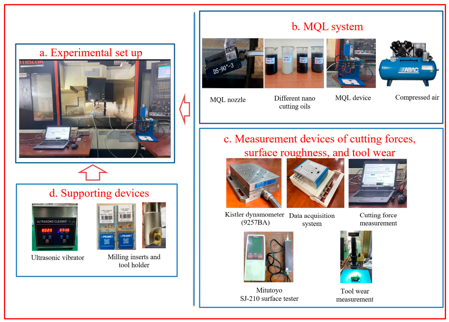
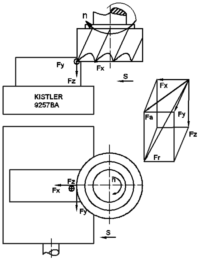
The milling experiments were conducted on a Mazak Vertical Center Smart 530C, and the experimental device setup is shown in Figure 1. The S-APMT 1604 PDER Grade 8230S titanium-coated inserts made by PRAMET (Sumperk, Czech Republic) were mounted on the 25A6R024A25-SAD07D-C milling head. The geometric parameters of the insert in the static state are as follows: the insert shape is a parallelogram with a side length of 17.01 mm, the insert thickness is 4.76 mm, the clearance angle is 11°, and the nose radius is 0.8 mm. During the cutting process, the cutting parameters were fixed at a cutting speed (V) of 50 m/min, a cutting depth (ap) of 0.5 mm, and a feed rate (f) of 0.12 mm/tooth, which were based on the previous works [23,28]. The Hastelloy C276 alloy workpiece had the dimensions of 154 mm × 36.8 mm × 57 mm and a hardness of 30–32 HRC. The chemical composition and mechanical properties of the Hastelloy C276 alloy are given in Table 1 and Table 2. The external MQL system shown in Figure 1 was used with the nozzle positioned towards the flank face of the cutting tool. The values of surface roughness were measured three times by using a Mitutoyo SJ-210 portable surface roughness tester (Mitutoyo Corporation, Kawasaki, Kanagawa, Japan) after each cutting trial, and the average values were taken. The three cutting force components (Fx, Fy, and Fz) were measured directly during the cutting process by Kistler 9257BA multicomponent dynamometers (Kistler Instruments (Pte) Ltd., Midview, Singapore) connected to the DQA N16210 A/D data (National Instruments, Austin, TX, USA). The designation of cutting forces is illustrated in Figure 2. The feed force component Fx acts in the direction of the tool’s feed motion, while Fy is the passive force which acts perpendicular to both the feed and cutting directions. The cutting force Fz acts tangentially to the rotational direction of the workpiece and is also called the primary force. The sampling frequency of cutting force measurement is 0.001 s. Dasylab 10.0 software was used to collect and process the experimental data. From the measured values of cutting forces, the active cutting force Fa is determined from the two force components Fx and Fy given by Equation (1).
F a = F x 2 + F y 2

2.2. Preparation of Nano Cutting Oils

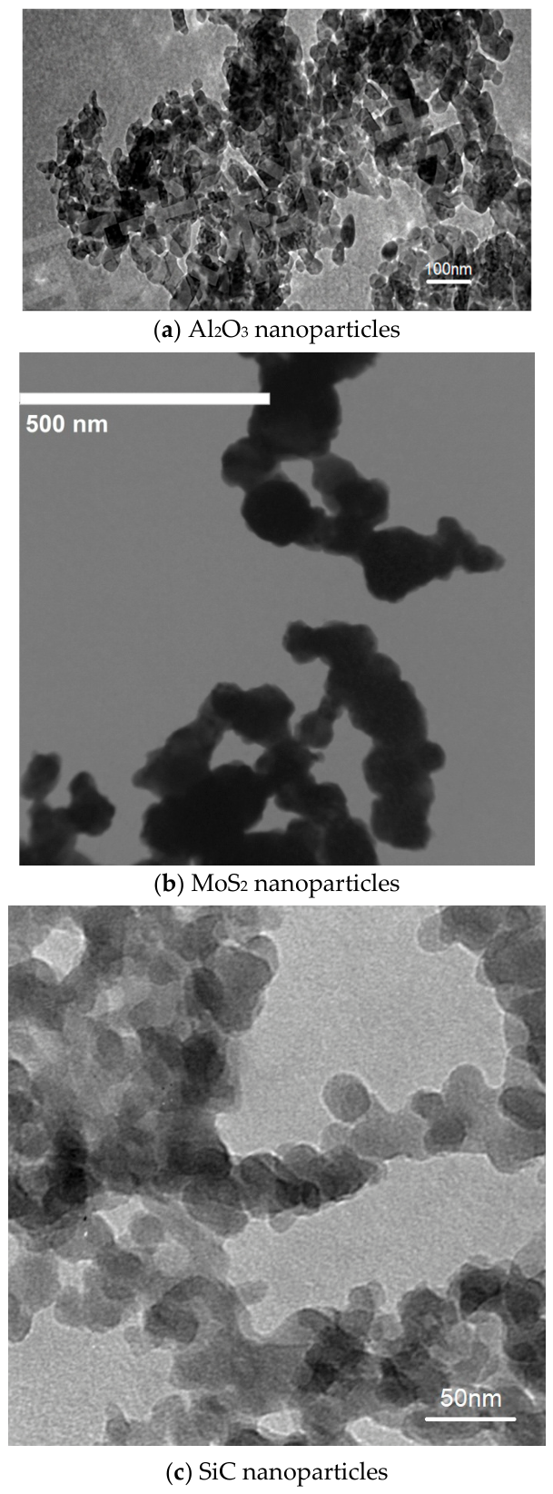
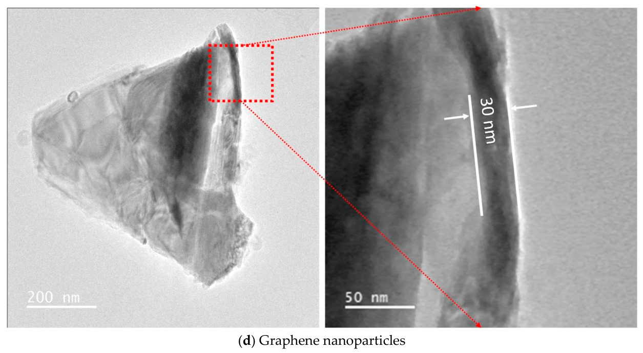
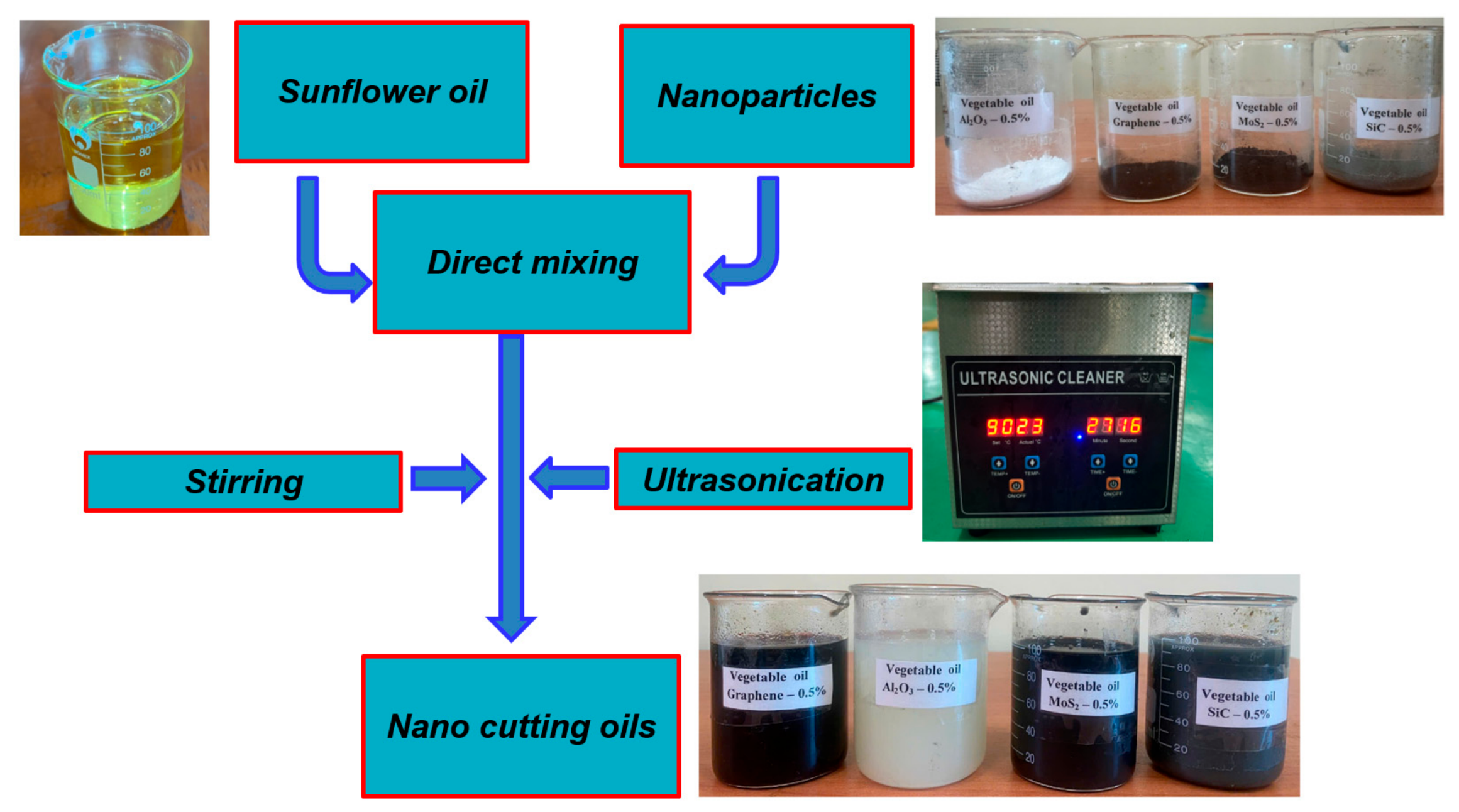
The nanoparticles were suspended in the nano-based sunflower oil with the same concentration of 0.5 wt% based on the literature of the published works [23,30,31,32]. All nanoparticles used in this study have a grain size of 30 nm, and their TEM images are shown in Figure 3. The preparation of nano cutting oils was conducted by a mechanical stirring process and then subjected to ultrasonic agitation by using a TB-50 Ultrasonic Cleaner device (AG Sonic Technology Limited, Shenzhen, China) for 1 h to reach the uniform distribution of nanoparticles in the nano-based oil (Figure 4). The obtained nano cutting oils were used for the MQL system. In order to evaluate the lubrication and cooling effectiveness, the milling experiments were conducted under various conditions including dry, MQL with pure vegetable oil, and MQL using vegetable oil containing different types of nanoparticles. The sequential experimental trials were conducted for dry, MQL, Graphene NF MQL, Al2O3 NF MQL, MoS2 NF MQL, and SiC NF MQL conditions. For each cooling lubrication environment, the milling process was implemented until the machinability of the cutting tool reached its limit. The experimental trial was repeated three times, and the cutting forces which were directly measured during the cutting process were taken by the average values. The measurement results of surface roughness and the cutting force components are shown in Appendix A Table A1, Table A2, Table A3, Table A4, Table A5 and Table A6.

3. Result and Discussion

3.1. Analysis of Cutting Forces and Tool Wear in Dry Milling Process

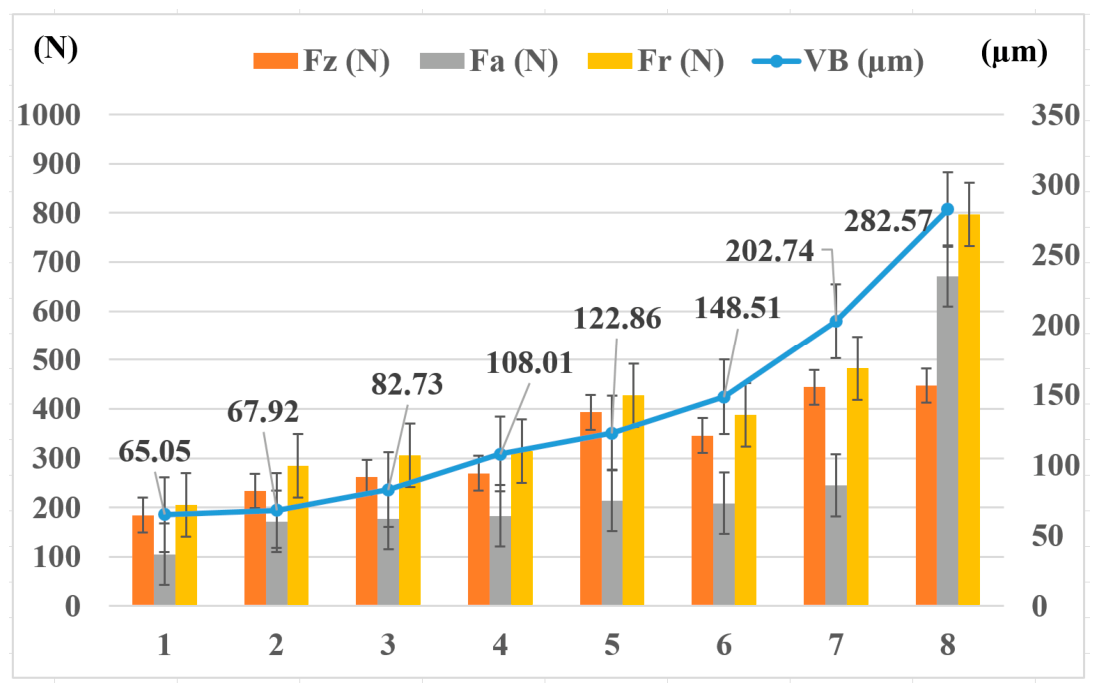
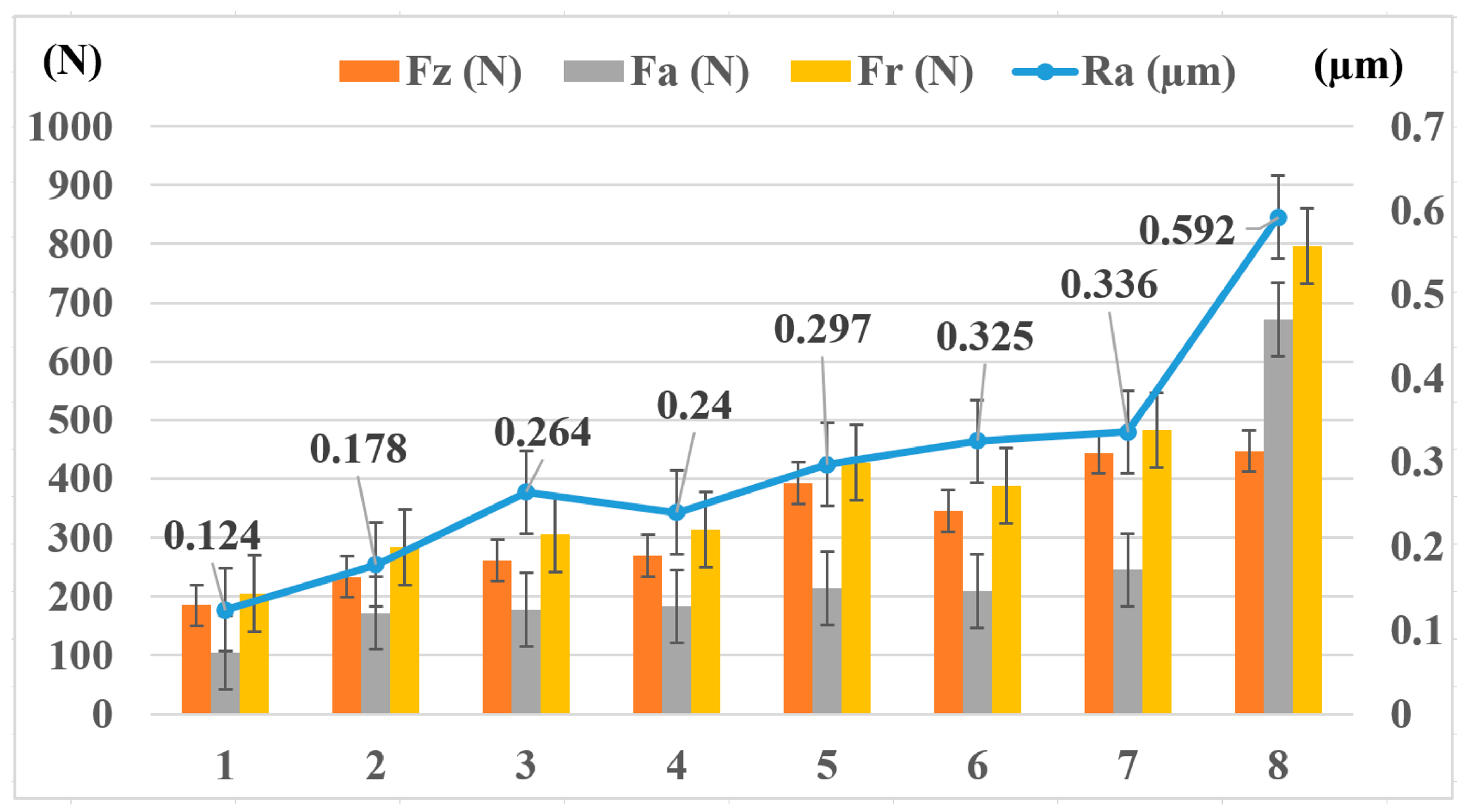
To investigate the surface roughness, cutting force, and tool wear during the milling process of the Hastelloy C276 alloy, each cutting trial was performed under fixed cutting parameters. After each trial, the surface roughness was measured by using a Mitutoyo SJ-210 surface roughness tester (Shenzhen Hayear Electronics Co., Ltd, Shenzhen, Guangdong, China), and the flank wear was measured by using a Hayear digital microscope (Shenzhen Hayear Electronics Co., Ltd, Shenzhen, Guangdong, China). The variation of flank wear and cutting force components is shown in Figure 5. The changes in surface roughness and cutting force are shown in Figure 6.
Figure 5. Flank face wear and cutting forces with the number of passes in milling Hastelloy C276 superalloy.
Fluids 11 00123 g005
Figure 6. Surface roughness and cutting forces with the number of passes in milling Hastelloy C276 superalloy.
Fluids 11 00123 g006
The results show that in the first seven passes, the cutting force components gradually increase with the growth of the wear land and surface roughness. Among the cutting force components, the active cutting force Fa increases slowly, while the passive cutting force increases more sharply from about 200 N to over 400 N. However, by the eighth pass, the cutting force increases abruptly, especially the active cutting force because significant tool wear occurs and the chipping is severe. Accordingly, the surface roughness also increases sharply. The eighth cutting trial indicates the machinability of the cutting insert reaches the limitation; therefore, during machining, the cutting inserts should be avoided when the active cutting force increases dramatically, as both wear and surface roughness will exceed the permissible limits. The cutting process should only stop when the cutting force Fz increases to approximately 400–500 N and the surface roughness values increase to 0.32 µm. At that point, the flank wear begins to reach its limit value of approximately 200 µm [6]. This is a reference limit for machining processes under different lubrication methods.

3.2. Effects of Different Cooling and Lubrication Methods on Surface Roughness

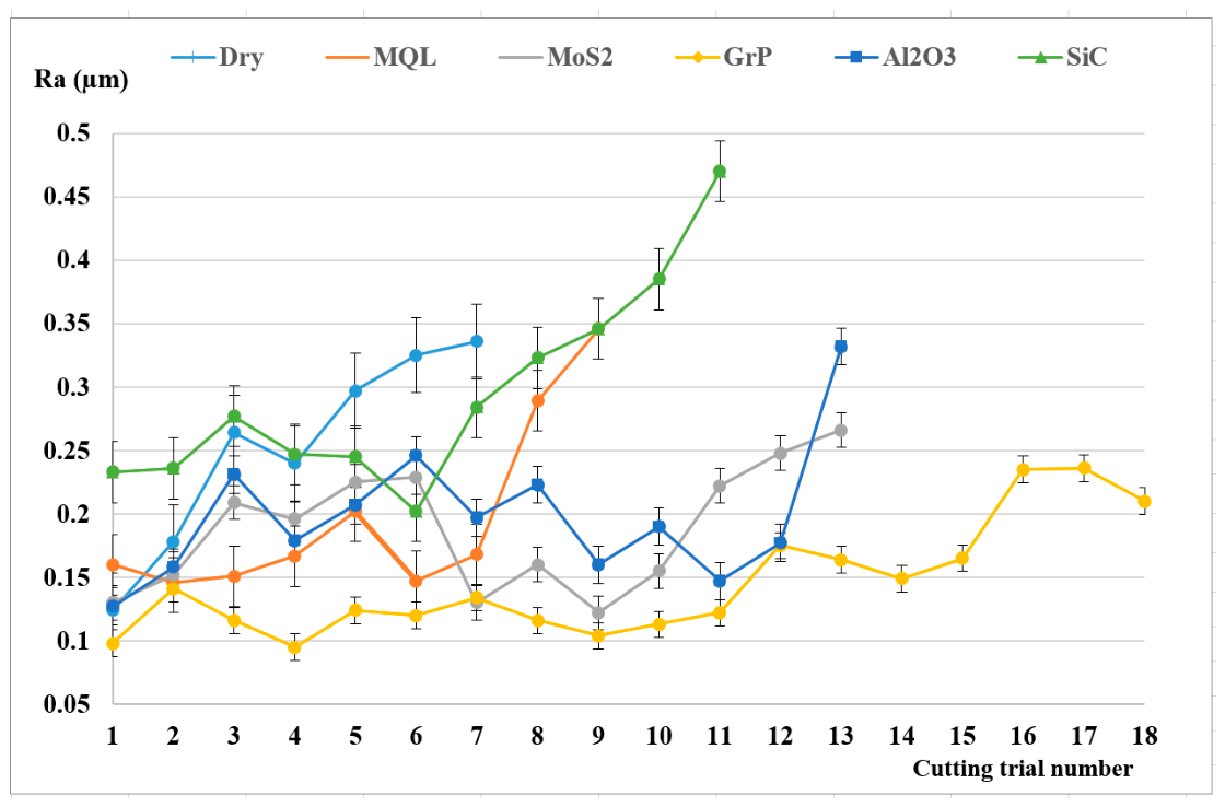
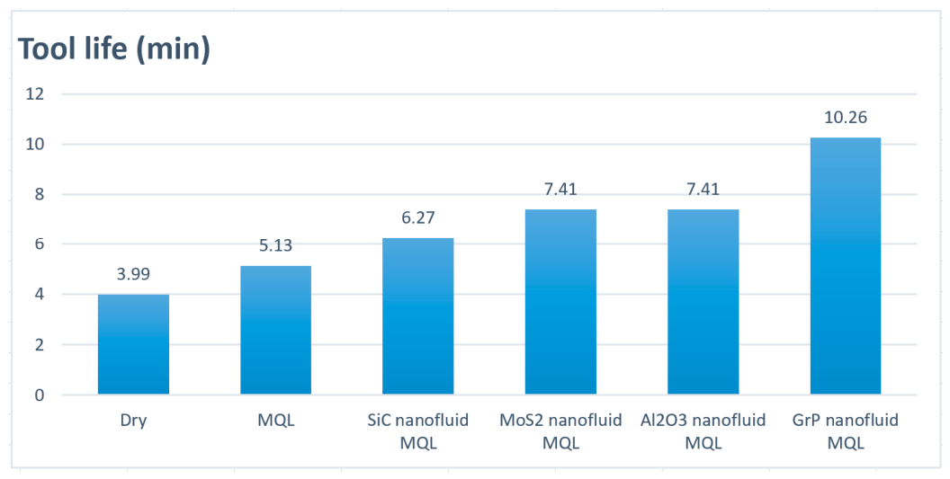
Figure 7 presents the variation of surface roughness values under different cooling and lubrication conditions. The results show that, in general, surface roughness tends to increase gradually after each cut, due to the cutting tool’s tendency to wear down, reducing its cutting ability. Dry machining resulted in the fewest number of cuts (seven times), followed by MQL and NF MQL with different types of nanoparticles. The ability to maintain surface roughness after each cut also indicates the tool life. From the experimental results in Figure 7 and Figure 8, the surface roughness exceeds 0.32 µm after seven cuts (about 3.99 min) under dry cutting, and under the MQL condition, it exceeds nine passes (about 5.13 min). Meanwhile, the graphs of MQL using Al2O3 and MoS2 nano cutting oils extend significantly further to the right of the horizontal axis with 13 passes (about 7.41 min) compared to dry and pure MQL modes. This demonstrates that nano cutting oils effectively reduce friction, cutting heat, and cutting force, helping to maintain surface roughness for longer time. MQL using GrP nano cutting oil achieves the largest number of passes with 18 (about 10.26 min). In general, the tool life was improved under nanofluid MQL in comparison with dry and pure MQL. The life span of the cutting tool was about 61.1% (GrP nanofluid MQL), 46.2% (Al2O3 and MoS2 nanofluid MQL), and 36.4% (SiC nanofluid MQL) higher than that of dry cutting. Compared to pure MQL, increasing tool life was reported by 50% (GrP nanofluid MQL), 30.8% (Al2O3 and MoS2 nanofluid MQL), and 18.2% (SiC nanofluid MQL) (Figure 8).
The slopes of the graphs of different cooling and lubrication conditions are significantly varied. The slopes of the NF MQL graphs using Al2O3, MoS2, and GrP nanoparticles are lower and more steady than those of dry, MQL and NF MQL using SiC nanofluid. Compared to dry and pure MQL in Table 3, GrP nanofluid MQL achieves the significant reduction in surface roughness Ra at about 54.3% and 34%, and MoS2 nanofluid MQL ranks second with about 23.7% and 7.7%, followed by Al2O3 nanofluid MQL with about 21.7% and 1.5%. Both GrP and MoS2 nanoparticles have layered nanosheets [24,25]. They are also called solid lubricating nanoparticles with high thermal conductivity, thus reducing cutting heat and friction in the cutting zone, resulting in finer and longer-lasting surface roughness. At the same time, the nearly spherical morphology of Al2O3 nanoparticles not only converts the sliding friction to rolling fiction in the contact zones [23,30], but also creates polishing effects on the machined surface [19]. Hence, the surface roughness values are reduced when compared to dry and MQL conditions. This suggests that the surface roughness is improved and better maintained due to the presence of nanoparticles. In contrast, SiC nanoparticles have high hardness, so they scratch the machined surface and potentially damage the cutting tool, resulting in higher surface roughness and poorer surface roughness retention compared to other surveyed types of nanoparticles. Thus, surface roughness analysis under various cooling and lubrication conditions shows that NF MQL technology using Al2O3, MoS2, and GrP nanoparticles can improve and maintain good surface quality better in the milling of the Hastelloy C276 alloy. Among the different types of nanoparticles surveyed, MQL using GrP nano cutting oil resulted in the smallest values of surface roughness and maintained them for the longest time. However, further studies are needed to confirm and propose suitable cutting and MQL parameters in the case of MQL using different nanofluids.

3.3. Influence of Different Cooling and Lubrication Methods on Cutting Force Components

  • Effect on the active cutting force Fa
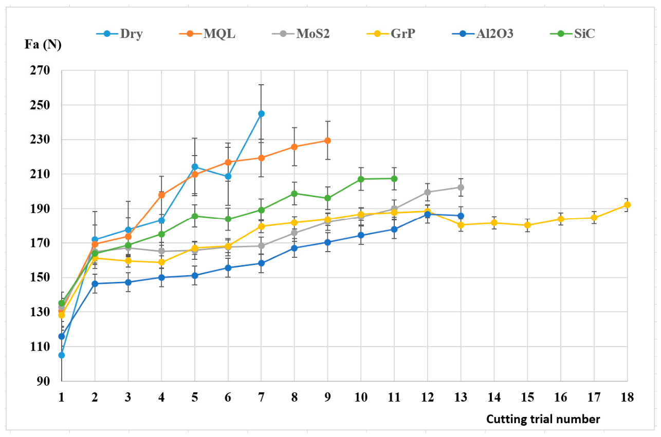
The active cutting force during the milling process is the resultant force in the working plane, determined by the vector sum of the principal tangential cutting force and the radial feed force, representing the energy required to remove material. This force is directly related to the power required for the cutting process, affects machine vibration, and determines the degree of tool deformation, thereby impacting surface smoothness and accuracy. The graph shows the variation of the active cutting force with the number of cuts, clearly reflecting the impact of lubrication and cooling conditions on cutting performance and tool wear. The tool gradually wears down during the cutting process, leading to a gradual increase in the active cutting force after each cut. Dry machining results in the highest active cutting force and the steepest slope of the graph. This indicates that the dry friction generates significant heat, causing severe tool wear and built-up edge (BUE), resulting in a sudden increase in the cutting forces.
In Figure 9, under MQL environments using GRP and MoS2 nanofluids, the lowest and most stable cutting forces are usually achieved. It can be explained that these materials have a layered structure (2D/lamellar structure), allowing them to easily slide over each other under cutting pressure, creating excellent solid lubrication properties and minimizing friction [31]. Compared to dry and pure MQL in Table 4, Al2O3 nanofluid MQL achieves the largest Fa reduction with the average percentage of about 18.4% and 22.1%, followed by GrP nanofluid MQL (about 12.8% and 16.6%), MoS2 nanofluid MQL (about 9.8% and 12.3%), and SiC nanofluid MQL (about 5.0% and 2.2%), respectively. A combination of tribological and secondary cutting mechanisms of Al2O3 nanoparticles contribute to the best results. They have high hardness and high load-bearing capacity and create the rolling effect in order to convert a portion of sliding friction into rolling friction, thereby significantly reducing the force in the feed direction—a force component that is highly sensitive to surface friction. In addition, Al2O3 has high thermal stability, not decomposing under high cutting temperatures, thus maintaining a continuous lubricating film, thereby reducing the adhesion and the formation of BUE on the tool face [23], which is a cause of increased chip drag in the feed direction. Due to their layered structure, GrP and MoS2 nanoparticles are easily broken under high pressure in the direction of tool movement [31,32]; thus, GrP and MoS2 nanofluid MQL have lower efficiency. However, the slopes of the cutting force curves of Grp and MoS2 are the gentlest, which demonstrates that these nanoparticles help maintain cutting edge sharpness for longer, reduce tool wear, and ensure more stable milling performance in comparison to the sudden increase in cutting forces in the dry environment. Thus, the application of NF MQL, especially with layered nanoparticles such as Graphene or MoS2, is a promising solution for reducing cutting forces and extending tool life when milling difficult-to-machine materials like Hastelloy C276. On the other hand, SiC nanoparticles possess very high hardness but are often angular in shape and not easily deformed [34]. Therefore, when entering the tool-chip contact zone, they do not create a rolling effect like Al2O3, but instead easily cause micro-abrasion, which increases sliding friction and even creates additional resistance in the direction of tool movement.
b.
Passive cutting force
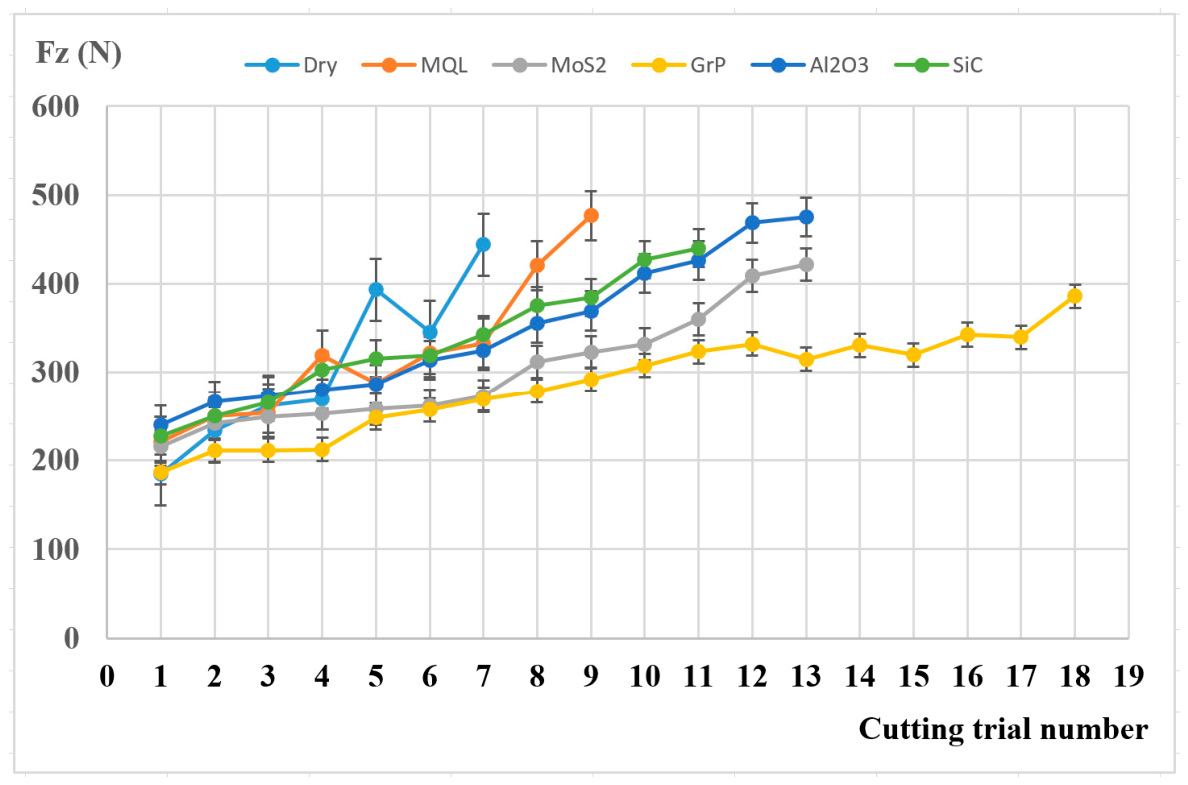
In the face milling process, the passive cutting force, also known as the radial force/normal force, is the force component, which is perpendicular to the surface being machined, tending to push the tool away from the workpiece [35]. This force component plays a crucial role in determining the geometric quality of the workpiece. For materials with high elasticity and strength like Hastelloy C276, the passive force is often very large due to the spring-back effect of the material on the flank face of the cutting tool [3]. The larger the value of Fz is, the higher the risk of tool deflection, causing dimensional errors and chatter. Therefore, the control of the cutting force Fz is key to guarantee the machining accuracy.
It was noticeable that in dry cutting, the figure of the passive force steeply increases, which not only indicates rapid tool wear but also reflects intense work hardening of the machined surface of Hastelloy C276 [4]. This hardened surface layer generates a very large elastic reaction force pushing against the cutting tool, causing the machining system to become unstable [9].
In the case of using Graphene (Grp) and MoS2 nano cutting oils, the growing rate of the passive force is lowest and the graph is flatter (Figure 10). Specifically, GrP nanofluid MQL shows the highest percentage of Fz reduction at about 13.4% and 26% when compared to the dry and pure MQL conditions, followed by MoS2 nanofluid MQL with about 5.7% and 16% (Table 5). It proves that the 2D-layered nanoparticles have penetrated the tight contact area on the flank face of the cutting tool, forming a “buffering membrane” separating the tool’s flank face from the elastic surface of the workpiece. This minimizes sliding friction and reduces material adhesion to the flank face of the insert, maintaining the low passive cutting force Fz, ensuring the tool not to be pushed away, and maintaining dimensional accuracy across multiple cuts.
Although Al2O3 and SiC nano cutting oils also contribute to reducing the passive cutting force better than the dry condition over time, the Fz values are generally higher than those of Grp and MoS2 nano cutting oils. Also, the average values of Fz are even slightly higher than those of dry and pure MQL modes (Table 5). The main reasons are that these types of nanoparticles have very high hardness (even harder than the workpiece), they can cause micro-ploughing or act as abrasive particles when sandwiched between the back of the tool and the elastic workpiece surface. Hence, the normal force component is slightly higher than that resulting from the smooth sliding mechanism of Grp and MoS2 nanoparticles.
In short, it can be confirmed from the passive force diagram that milling under NF MQL with layered nanostructured particles (Grp, MoS2) not only helps reduce the cutting forces but, more importantly, enhances the kinematic rigidity of the process. The low passive force means minimized tool wear and vibration, which is a prerequisite for achieving high surface finish and low geometric error in manufacturing precision parts from Hastelloy alloys.

4. Conclusions

In this paper, the influences of MQL using different types of nanoparticles (Al2O3, MoS2, SiC, and GrP) enriched in vegetable oil on the milling performance of Hastelloy C276 was studied and compared to the dry and pure MQL conditions. The response factors include surface roughness Ra and active cutting forces Fa and passive cutting force Fz. The main contributions of the study are summarized as follows:
A nanofluid MQL environment reduces surface roughness and cutting forces more effectively than the dry and pure MQL methods, resulting in the significant improvement of tool life about 36.4 ÷ 61.1% and 18.2 ÷ 50%, respectively. MQL using graphene nanofluid achieved the best results among the surveyed strategies with the remarkable reduction in surface roughness Ra at about 54.3% and 34%, followed by MoS2 nanofluid MQL with about 23.7% and 7.7% and Al2O3 nanofluid MQL with about 21.7% and 1.5%.
The different types of nanoparticles result in various cooling and lubricating mechanisms. Graphene (Grp) and MoS2 nanoparticles have a layered structure and create a “buffering membrane” to separate the tool’s flank face from the elastic surface of the workpiece when penetrating the contact zone. Meanwhile, Al2O3 and SiC possess the nearly spherical morphology and high hardness, so they will act as “ball rollers” or abrasive material, causing micro-ploughing or polishing on the machined surface.
Regarding the machinability of Hastelloy C276, the nanoparticles having a layered structure present better performance than those with spherical morphology and high hardness, which is confirm by in-depth analysis of the variation of active and passive cutting forces Fa and Fz. Looking in detail, Al2O3 nanofluid MQL is the most effective in the Fa reduction of about 18.4% and 22.1%, while GrP nanofluid MQL reduces Fz the most at about 13.4% and 26% when compared to the dry and pure MQL conditions.
Despite the promising obtained results, there are several remaining limitations. The study was implemented with a single material and fixed machining conditions. In future scope, more investigations should be focused on the finding of the optimization results of nanoparticle concentration and MQL factors such as oil flow rate, nozzle angle and placement. Tool wear and surface microstructure need to be studied deeply in order to confirm the cooling and lubricating mechanisms of different types of nanoparticles. Additionally, a cost comparison between milling using nano cutting oils and dry cutting is necessary to assess their practicality in production.


Author Contributions

Conceptualization, N.T.D., N.M.T. and T.T.L.; methodology, N.M.T. and V.L.H.; software, N.T.D. and T.T.L.; validation, N.T.D., and T.T.L.; formal analysis, N.M.T. and T.T.L.; investigation, V.L.H.; resources, N.M.T.; data curation, V.L.H.; writing—original draft preparation, N.T.D., N.M.T., and T.T.L.; writing—review and editing, N.M.T., and T.T.L.; visualization, N.T.D.; supervision, N.M.T. and T.T.L.; project administration, N.M.T.; funding acquisition, N.T.D. All authors have read and agreed to the published version of the manuscript.

Funding

The work presented in this paper is funded by Thai Nguyen University of Technology, Thai Nguyen University, Vietnam.

Institutional Review Board Statement

Not applicable.

Informed Consent Statement

Not applicable.

Data Availability Statement

The original contributions presented in the study are included in the article, further inquiries can be directed to the corresponding author.

Acknowledgments

The authors acknowledge the support provided by Thai Nguyen University of Technology, Thai Nguyen University, Vietnam for the completion of this research work.

Conflicts of Interest

The authors declare no conflict of interest.

Appendix A

Table A1. Experimental results of dry milling condition (V = 50 m/min, f = 0.12 mm/tooth, and ap = 0.5 mm).
Cutting Trial NumberRa (µm)Fz (N)Fa (N)
10.124184.7105.2
20.178233.6171.8
30.264261.6177.5
40.24269.2183.2
50.297393214.2
60.325425.7234.7
70.336487244.9
Table A2. Experimental results of MQL milling condition (V = 50 m/min, f = 0.12 mm/tooth, and ap = 0.5 mm).
Cutting Trial Number NghiệmRa (µm)Fz (N)Fa (N)
10.16221.08130.6158
20.146250.03169.2149
30.151253.64173.6581
40.167319.25197.7176
50.202287.31209.716
60.147321.83216.8292
70.168332.9219.2961
80.289420.36225.8087
90.346476.67229.3642
Table A3. Experimental results of MoS2 NF MQL milling condition (V = 50 m/min, f = 0.12 mm/tooth, and ap = 0.5 mm).
Cutting Trial NumberRa (µm)Fz (N)Fa (N)
10.13215.22132.7896
20.152242.27164.8325
30.209249.48167.0829
40.196252.66165.1844
50.225257.73165.5715
60.229261.6167.4718
70.13272.94168.2658
80.16311.56175.7641
90.122322.98182.1802
100.155331.57185.2555
110.222359.67190.0142
120.248408.65199.5866
130.266421.16202.3887
Table A4. Experimental results of Graphene NF MQL milling condition (V = 50 m/min, f = 0.12 mm/tooth, and ap = 0.5 mm).
Cutting Trial NumberRa (µm)Fz (N)Fa (N)
10.098186.33128.1639
20.141210.84161.2056
30.116211.26159.6269
40.095212.31158.802
50.124248.13166.9809
60.12257.04168.0531
70.134269.2179.5784
80.116278.44181.7377
90.104291.84183.7055
100.113307.58186.782
110.122323.29187.7482
120.175331.84188.3972
130.164314.75180.2891
140.149330.67181.6589
150.165319.78180.1908
160.235342.6183.9011
170.236339.62184.7258
180.21386.01192.1637
Table A5. Experimental results of Al2O3 NF MQL milling condition (V = 50 m/min, f = 0.12 mm/tooth, and ap = 0.5 mm).
Cutting Trial NumberRa (µm)Fz (N)Fa (N)
10.127239.7115.8943
20.158266.71146.3827
30.231272.5147.2659
40.179280.37150.0096
50.207286.32151.1434
60.246313.46155.5369
70.197324.74158.1537
80.223355.72166.9714
90.16369.29170.3857
100.19411.44174.4155
110.147425.94177.8614
120.177468.38186.7595
130.232475.15185.8814
Table A6. Experimental results of SiC NF MQL milling condition (V = 50 m/min, f = 0.12 mm/tooth, and ap = 0.5 mm).
Cutting Trial NumberRa (µm)Fz (N)Fa (N)
10.233227.74135.0894
20.236249.88163.8206
30.277265.67168.6118
40.247302.27175.0895
50.245315.38185.703
60.242319.16183.808
70.284342.56189.2711
80.323374.94198.8065
90.346384.48196.0688
100.385427.21207.1606
110.47440.07207.356

References

  1. Thakur, A.; Gangopadhyay, S. State-of-the-art in surface integrity in machining of nickel-based super alloys. Int. J. Mach. Tools Manuf. 2016, 100, 25–54. [Google Scholar] [CrossRef]
  2. Kenda, J.; Pusavec, F.; Kopac, J. Analysis of residual stresses in sustainable cryogenic machining of nickel based alloy—Inconel 718. J. Manuf. Sci. Eng. 2011, 133, 041009. [Google Scholar] [CrossRef]
  3. Zhu, D.; Zhang, X.; Ding, H. Tool wear characteristics in machining of nickel-based superalloys. Int. J. Mach. Tools Manuf. 2013, 64, 60–77. [Google Scholar] [CrossRef]
  4. Ezugwu, E.O.; Wang, Z.M.; Machado, A.R. The machinability of nickel-based alloys: A review. J. Mater. Process. Technol. 1999, 86, 1–16. [Google Scholar] [CrossRef]
  5. Akhtar, W.; Sun, J.; Sun, P.; Chen, W.; Saleem, Z. Tool wear mechanisms in the machining of nickel based super-alloys: A review. Front. Mech. Eng. 2014, 9, 106–119. [Google Scholar] [CrossRef]
  6. Kadirgama, K.; Abou-El-Hossein, K.A.; Noor, M.M.; Sharma, K.V.; Mohammad, B. Tool life and wear mechanism when machining Hastelloy C-22HS. Wear 2011, 270, 258–268. [Google Scholar] [CrossRef]
  7. Suárez, A.; Veiga, F.; de Lacalle, L.N.L.; Polvorosa, R.; Wretland, A. An investigation of cutting forces and tool wear in turning of Haynes 282. J. Manuf. Process. 2019, 37, 529–540. [Google Scholar] [CrossRef]
  8. Polvorosa, R.; Suárez, A.; de Lacalle, L.N.L.; Cerrillo, I.; Wretland, A.; Veiga, F. Tool wear on nickel alloys with different coolant pressures: Comparison of Alloy 718 and Waspaloy. J. Manuf. Process. 2017, 26, 44–56. [Google Scholar] [CrossRef]
  9. Modi, V.A.; Kumar, P.; Malik, R.; Yadav, A.S.; Pandey, A. Analysis of optimized turning parameters of Hastelloy C-276 using PVD coated carbide inserts in CNC lathe under dry condition. Mater. Today Proc. 2021, 47, 2929–2948. [Google Scholar] [CrossRef]
  10. Oschelski, T.B.; Cardoso, M.T.; Silva, L.F. Effect of Cutting Conditions on Surface Roughness in Finish Turning Hastelloy X Superalloy. Mater. Today Proc. 2021, 44, 3170–3174. [Google Scholar] [CrossRef]
  11. Singh, S.; Chohan, J.S.; Singh, G. Experimental investigation into machining of hastelloy C-276 during different cooling environments. Mater. Today Proc. 2022, 48, 1123–1129. [Google Scholar] [CrossRef]
  12. Wang, S.; Zhao, S.; Xu, R.; Huang, L.; Sun, Z. An investigation on subsurface generation in ultra-precision milling of nickel with multiscale crystal plasticity FE model. J. Manuf. Process. 2025, 141, 815–828. [Google Scholar] [CrossRef]
  13. Sivalingam, V.; Sun, J.; Mahalingam, S.K.; Nagarajan, L.; Natarajan, Y.; Salunkhe, S.; Nasr, E.A.; Davim, J.P.; Hussein, H.M.A.M. Optimization of Process Parameters for Turning Hastelloy X under Different Machining Environments Using Evolutionary Algorithms: A Comparative Study. Appl. Sci. 2021, 11, 9725. [Google Scholar] [CrossRef]
  14. Dhananchezian, M. Study the Machinability Characteristics of Nickel-Based Hastelloy C-276 under Cryogenic Cooling. Measurement 2019, 136, 694–702. [Google Scholar] [CrossRef]
  15. Wang, F.; Wang, Y. Comparison of cryogenic cooling strategy effects on machinability of milling nickel-based alloy. J. Manuf. Process. 2021, 66, 623–635. [Google Scholar] [CrossRef]
  16. Shokrani, A.; Newman, S.T. Hybrid cooling and lubricating technology for CNC milling of Inconel 718 nickel alloy. Procedia CIRP 2018, 77, 215–218. [Google Scholar] [CrossRef]
  17. Singh, G.; Aggarwal, V.; Singh, S.; Singh, B. Sustainable machining of Hastelloy C-276 enabling minimum quantity lubrication of environmentally compatible lubricants. J. Clean. Prod. 2022, 373, 133928. [Google Scholar] [CrossRef]
  18. Cai, L.; Feng, Y.; Liang, S.Y. Analytical Modelling of Cutting Force in End-Milling with Minimum Quantity Lubrication. Int. J. Precis. Eng. Manuf. 2024, 25, 899–912. [Google Scholar] [CrossRef]
  19. Sharma, A.K.; Tiwari, A.K.; Dixit, A.R. Mechanism of Nanoparticles Functioning and Effects in Machining Processes: A Review. Mater. Today Proc. 2015, 2, 3539–3544. [Google Scholar] [CrossRef]
  20. Duc, T.M.; Ngoc, T.B.; Tuan, N.M.; Long, T.T. An optimization study on Al2O3 nanoparticle concentration, air pressure, and air flow rate in MQL hard turning. Adv. Mech. Eng. 2025, 17, 1–16. [Google Scholar] [CrossRef]
  21. Venkatesan, K.; Devendiran, S.; Nishanth Purusotham, K.; Praveen, V.S. Study of machinability performance of Hastelloy-X for nanofluids, dry with coated tools. Mater. Manuf. Process. 2020, 35, 751–761. [Google Scholar] [CrossRef]
  22. Sen, B.; Saha, S.; Kumar, R.; Jhala, R.; Patil, N.; Mahapatro, A.; Bhowmik, A.; Santhosh, A. AI-driven wear monitoring of PVD TiAlN coated carbide insert in sustainable machining of Hastelloy C276: An industry 4.0 perspective. Results Eng. 2025, 25, 104457. [Google Scholar] [CrossRef]
  23. Günan, F.; Kıvak, T.; Yıldırım, Ç.V.; Sarıkaya, M. Performance evaluation of MQL with Al2O3 mixed nanofluids prepared at different concentrations in milling of Hastelloy C276 alloy. J. Mater. Res. Technol. 2020, 9, 10386–10400. [Google Scholar] [CrossRef]
  24. Sharma, S.; Late, D.J. Molybdenum Disulfide (MoS2) as an Efficient Solid Lubricant. In Science and Technology of 2D MoS2; Late, D.J., Rout, C.S., Eds.; Materials Horizons: From Nature to Nanomaterials; Springer: Singapore, 2024. [Google Scholar] [CrossRef]
  25. Bharadwaj, G.; Sharma, K.; Pandey, A.K.; Gupta, A. Carbon nanotube–graphene-based nanofluids: A comprehensive review on the role of thermal conductivity and its solar energy applications. J. Therm. Anal. Calorim. 2024, 149, 1859–1893. [Google Scholar] [CrossRef]
  26. Sen, B.; Bhowmik, A. Application of minimum quantity GnP nanofluid and cryogenic LN2 in the machining of Hastelloy C276. Tribol. Int. 2024, 194, 109509. [Google Scholar] [CrossRef]
  27. Abellán-Nebot, J.V.; Ameen, K.H.; Khan, A.M.; Mondragón, R. Application of Hybrid Nanofluids in MQL Assisted Machining Operations: Exploring Synergies and Establishing Guidelines. Int. J. Precis. Eng. Manuf. Green. Technol. 2025, 12, 657–689. [Google Scholar] [CrossRef]
  28. Chohan, J.S.; Samantaray, S.; Raja, V.K.B.; Patil, N.; Kaladhar, M.; Mann, V.S.; Abate, L.; Ghodhbani, R. Sustainable machining of heat resistant superalloys using hybrid nanofluid based minimum quantity lubrication. Sci. Rep. 2025, 15, 34069. [Google Scholar] [CrossRef]
  29. Khan, A.M.; Rahat, M.R.; Ahmed, U.; Jamil, M.; Ali, M.A.; Zhao, G.; Abellán-Nebot, J.V. The Recent Advancements in Minimum Quantity Lubrication (MQL) and Its Application in Mechanical Machining—A State-of-the-Art Review. Lubricants 2025, 13, 401. [Google Scholar] [CrossRef]
  30. Duc, T.M.; Long, T.T.; Dong, P.Q. Effect of the alumina nanofluid concentration on minimum quantity lubrication hard machining for sustainable production. Proc. Inst. Mech. Eng. Part C J. Mech. Eng. Sci. 2019, 233, 5977–5988. [Google Scholar] [CrossRef]
  31. Rahmati, B.; Sarhan, A.A.; Sayuti, M. Morphology of surface generated by end milling AL6061-T6 using molybdenum disulfide (MoS2) nanolubrication in end milling machining. J. Clean. Prod. 2014, 66, 685–691. [Google Scholar] [CrossRef]
  32. Musavi, S.H.; Ganji, D.D. A comprehensive review on nanofluids applications in the machining industry: Challenges in nanofluids. Results Eng. 2026, 29, 109220. [Google Scholar] [CrossRef]
  33. Duc, T.M.; Long, T.T.; Chien, T.Q. Performance Evaluation of MQL Parameters Using Al2O3 and MoS2 Nanofluids in Hard Turning 90CrSi Steel. Lubricants 2019, 7, 40. [Google Scholar] [CrossRef]
  34. Zhang, G.; Chen, H.; Xiao, G.; Yi, M.; Chen, Z.; Zhang, J.; Wang, G.; Xu, C. Effect of SiC nanofluid minimum quantity lubrication on the performance of the ceramic tool in cutting hardened steel. J. Manuf. Process. 2022, 84, 539–554. [Google Scholar] [CrossRef]
  35. Davim, J.P.; Astakhov, V.P. Machining of Hard Metals; Springer: London, UK, 2011. [Google Scholar]
Figure 1. Set up diagram of face milling experiments and measurement.
Fluids 11 00123 g001
Figure 2. Designation of cutting force components in the face milling process.
Fluids 11 00123 g002
Figure 3. TEM images of the surveyed nanoparticles: (a) Al2O3 [33]; (b) MoS2 [33]; (c) SiC; (d) Graphene.
Fluids 11 00123 g003aFluids 11 00123 g003b
Figure 4. Preparation process of the different nano cutting oils.
Fluids 11 00123 g004
Figure 7. Surface roughness with the number of passes under different cooling and lubrication conditions.
Fluids 11 00123 g007
Figure 8. Tool life under different cooling and lubrication conditions.
Fluids 11 00123 g008
Figure 9. Effect of cutting time on the active cutting force Fa under dry, MQL, and MQL using different nano cutting oils.
Fluids 11 00123 g009
Figure 10. Effect of cutting time on the passive cutting force Fz under dry, MQL, and MQL using different nano cutting oils.
Fluids 11 00123 g010
Table 1. Chemical composition of Hastelloy C276 (according to UNS N10276).
NiMoCrFeWCoMnVCSiPS
57%15 ÷ 1714.5 ÷ 16.54.0 ÷ 7.03.0 ÷ 4.52.51.0 max0.35 0.010.08 max0.0250.01
Table 2. Mechanical Properties of Hastelloy C276 (according to UNS N10276).
Tensile Strength (MPa)Yield Strength (MPa)Elongation (%)Hardness (HRC)Modulus of Elasticity (GPa)
601.2204.85630–32205
Table 3. Average percentage of surface roughness Ra reduction compared to dry and pure MQL.
Cooling Lubrication ConditionsDryPure MQL
MoS2 nanofluid MQL≈23.7%≈7.7%
GrP nanofluid MQL≈54.3%≈34.0%
Al2O3 nanofluid MQL≈21.7%≈1.5%
SiC nanofluid MQL≈−2.9%≈−49.4%
Note: The sign “−“ means the increasing percentage.
Table 4. Average percentage of the active cutting force Fa reduction compared to dry and pure MQL.
Cooling Lubrication ConditionsDryPure MQL
MoS2 nanofluid MQL ≈9.8% ≈12.3%
GrP nanofluid MQL≈12.8%≈16.6%
Al2O3 nanofluid MQL≈18.4%≈22.1%
SiC nanofluid MQL≈5.0%≈2.2%
Table 5. Average percentage of cutting force Fz reduction compared to dry and pure MQL.
Cooling Lubrication ConditionsDryPure MQL
MoS2 nanofluid MQL ≈5.7 %≈16%
GrP nanofluid MQL≈13.4%≈26%
Al2O3 nanofluid MQL≈−1.1%≈−7.4%
SiC nanofluid MQL≈−4.9%≈−6.7%
Note: The sign “−“ means the increasing percentage.
Disclaimer/Publisher’s Note: The statements, opinions and data contained in all publications are solely those of the individual author(s) and contributor(s) and not of MDPI and/or the editor(s). MDPI and/or the editor(s) disclaim responsibility for any injury to people or property resulting from any ideas, methods, instructions or products referred to in the content.