1. Introduction
Filling processes in water-distribution systems are crucial, as water utilities periodically repeat these operations. In recent years, several authors have investigated the start-up of pressurised water systems to estimate the pressure surges arising from the compression of trapped air pockets during such transients, with the aim of preventing pipeline failures associated with this operation. Various numerical approaches have been employed to address this problem. Martin (1977) [
1] was the first to tackle the start-up of water pipelines using the rigid column theory, applying the fourth-order Runge–Kutta method as the numerical solution technique. Liou and Hunt (1996) [
2] adopted a Runge–Kutta method with adaptive step-size control. Coronado-Hernández et al. (2019) [
3] also utilised the rigid column theory, incorporating the location of air valves within the system and solving the governing equations using the Rosenbrock method, implemented in MATLAB’s Simulink environment (version R2024b). Zhou et al. (2013) [
4] applied the method of characteristics (MOC) to address the air–water interface, employing the elastic column theory with a moving boundary for the air–water interface. In practice, both the rigid and elastic column approaches produce comparable results, as the compressibility of air is significantly greater than that of pipe material and water [
5].
Various modelling approaches have been employed to characterise the behaviour of water-pressurised installations during start-up processes, in which pressure surge pulses may be observed. The dynamics of key variables during start-up processes have been examined not only through one-dimensional models, but also using two- and three-dimensional computational fluid dynamics (CFD) simulations. Huang et al. (2021) [
6] employed OpenFOAM (specifically the compressibleInterFoam solver) to simulate a rapid start-up event in water-conveyance systems. A significant advantage of such CFD models over one-dimensional approaches lies in their ability to represent inclined or non-vertical air–water interfaces, which are often observed in real-world systems. Aguirre et al. (2022) [
7] also utilised OpenFOAM to study filling processes in the presence of air valves within an experimental setup. Martins et al. (2017) [
8] used ANSYS Fluent with the Semi-Implicit Method for Pressure-Linked Equations (SIMPLE) to analyse the complex air–water interaction in a vertical–horizontal pipeline of 3.62 m in length. Similarly, Zhou et al. (2011) [
9] applied FLUENT version 6.2 in conjunction with the Finite Volume Method to simulate the transient behaviour in a 3.5 m long experimental facility. These processes have been simulated, thereby providing water utilities with reliable tools for operational manoeuvres.
Drainage processes in pressurised water pipelines have also been investigated through 1D, 2D, and 3D models [
10,
11,
12], resulting in robust frameworks capable of predicting the evolution of both hydraulic and thermodynamic variables. In addition, Tijsseling et al. (2015) [
11] developed an analytical formulation to track the air–water interface, based on a semi-empirical approach.
In the analysis of nonlinear dynamical systems, a classical strategy for dealing with second-order differential equations involves reducing their order through a change of variable that transforms the second derivative into the derivative of an auxiliary function, typically defined as the square of the first derivative. This procedure is widely used in mechanics and hydraulics to facilitate the integration of nonlinear models in contexts where explicit time dependence is absent, leading to more tractable autonomous equations [
13].
Although the existing literature comprises a greater number of studies concerning filling (start-up) operations than emptying manoeuvres, there is still no general analytical solution for simulating start-up processes involving entrapped air in pressurised water systems. Recently, the authors developed an analytical formulation to predict drainage processes involving entrapped air [
14].
Analytical solutions are of particular importance, as they offer water utilities straightforward tools that are more accessible than complete numerical solutions based on systems of differential equations. In this regard, such formulations can play a significant role in the development of digital twins [
15,
16,
17] during the start-up phase of pressurised systems, enabling the rapid identification of critical variables. Consequently, technical personnel can more effectively anticipate the conditions under which water infrastructure might fail due to pressure surges.
The present study introduces an analytical solution to the start-up problem in pressurised pipelines containing an entrapped air pocket. This solution enables the assessment of key variables such as air pocket pressure, water velocity, and the position of the air–water interface. The formulation is derived from a system of differential equations based on fundamental physical principles—namely, the mass oscillation equation, piston-flow dynamics, and the polytropic gas law—which is transformed into a first-order linear ordinary differential equation, ultimately yielding a closed-form solution. The proposed analytical model is applied to a case study involving an 800 m long pipeline with an internal diameter of 0.30 m. In addition, the solution is then validated against experimental data, demonstrating its accuracy and practical applicability.
2. Mathematical Model
In this section, a mathematical formulation is presented to describe the filling process of a pipeline containing a trapped air pocket. This type of problem has been previously addressed using rigid water column models by authors such as Martin (1976) [
1], Chaudhry (1989) [
18], and Liou and Hunt (1996) [
2], who demonstrated that, during the initial stage of filling, air compressibility plays a critical role in the generation of transient overpressures.
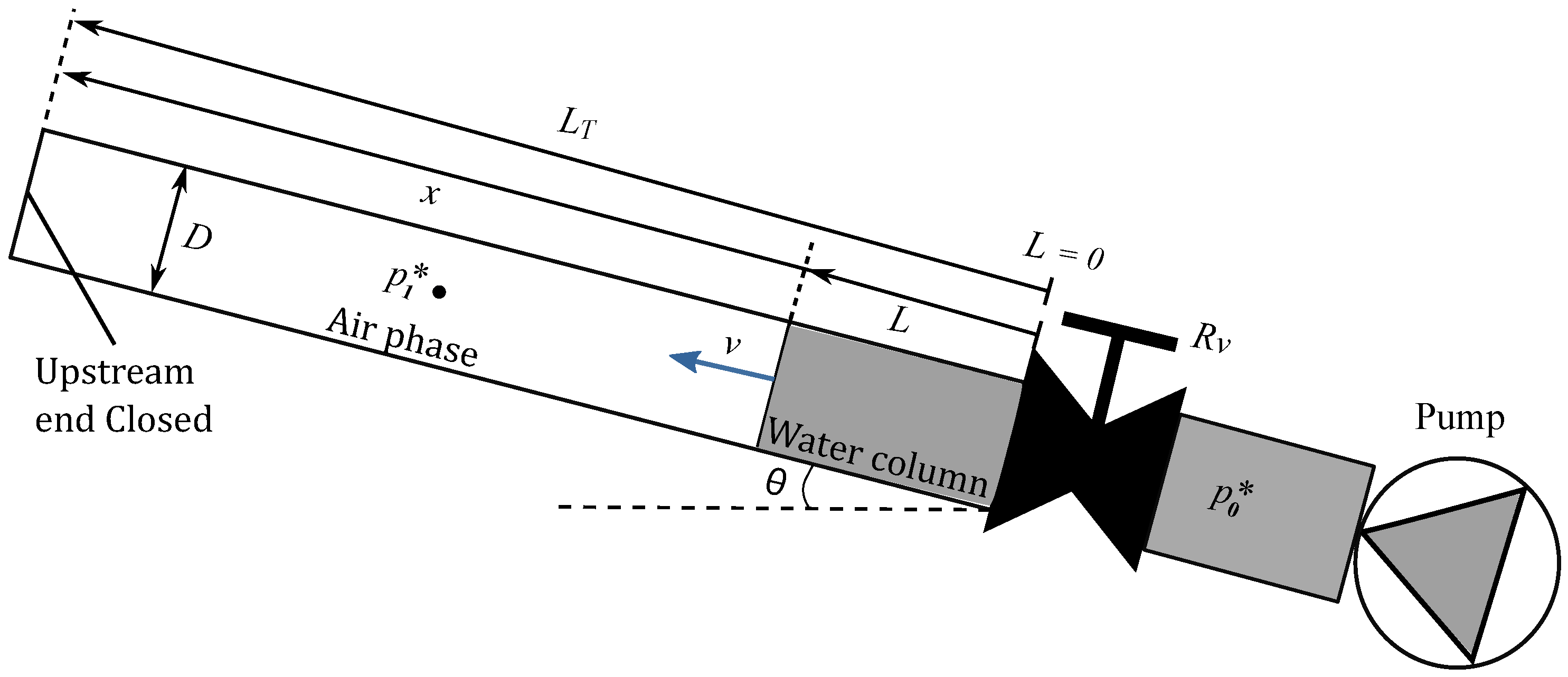
Figure 1 illustrates a conceptual diagram of a hydraulic system composed of a pipe segment connected to an energy source (e.g., a pump, hydropneumatic tank, or a reservoir), along with the main physical parameters involved, the relevant variables, and the reference system used to measure the displacement of the water column. For analysis, it is assumed that the energy source maintains an inlet pressure
, which can be constant or variable.
Initially, a regulating valve is closed, and the system is at rest. When it is suddenly opened, the water column begins to move through a pipe; as a consequence, the trapped air pocket is compressed. This phenomenon generates a non-uniform transient flow, in which the water front acts like a piston displacing an air pocket.
2.1. Physical Considerations of the System
As in the emptying process described in [
14], these physical considerations are assumed:
Rigid Water Column (RWC) [
2,
4]: The water column is assumed to be incompressible, given that the compressibility of air is several orders of magnitude higher than that of water. No air is admitted into a pipe during a filling process. The rigid model can be applied by considering a rigid inertia parameter with values ranging from 0.4 to 2.0, analysing only the water phase [
19]. It depends on a pipe diameter, a reference head, valve closure time, pipe length, and a reference flow rate.The elastic and rigid column models tend to yield similar results during filling operations with entrapped air pockets, as the elasticity of the system is primarily associated with the air phase [
5].
Constant geometric conditions: The pipe slope and the internal diameter D are assumed to remain constant throughout the system. The energy source (e.g., a centrifugal pump, a hydropneumatic tank, or a reservoir) maintains an inlet pressure, , throughout the entire filling operation.
Friction losses: A uniform roughness is assumed along the internal pipe surface, and the energy losses due to friction are modelled using the Darcy-Weisbach friction factor
f [
2,
4,
11,
20,
21].
Instantaneous valve opening: The regulating valve is assumed to open instantaneously at time . Its hydraulic resistance is represented by a constant coefficient , which accounts for local head losses associated with the valve.
Air compressibility: The absolute pressure
inside the trapped air pocket is modelled using the polytropic law. This law relates pressure and volume through a polytropic exponent
k, which depends on the thermal conditions of the air:
for an isothermal process,
for an adiabatic process, and intermediate values (e.g.,
) for polytropic behaviours [
4].
These assumptions are valid for pipelines with relatively small diameters or for pipelines with enough longitudinal slopes. In such cases, the air–water interface can be represented as a well-defined front, enabling the application of the piston flow model [
2]. The proposed model is suitable for representing both rigid and flexible pipes, characterised using the Darcy–Weisbach equations, which depend on the absolute roughness of the pipe (provided by catalogues), the Reynolds number, and the pipe diameter. The analytical model can be applied to various types of valves, characterised by their resistance coefficients. It is founded on physical equations and is capable of reproducing a wide range of scenarios, including the presence of hydro-pneumatic tanks or pumps. As standard practice, a check valve is installed downstream of a pumping station to protect against water hammer. However, during filling operations, the procedure should be undertaken as slowly as possible to minimise the risk of undesirable water hammer induced by entrapped air, as recommended by the American Water Works Association (AWWA) [
22]. In such situations, a regulating valve should be employed, which is precisely incorporated into the proposed model.
2.2. Transient Model of Pipe Filling with Trapped Air
Based on the considerations above, the filling phenomenon can be modelled through the following system of coupled ordinary differential equations:
Momentum equation: Following the RWC approach [
2], the system dynamics are modelled through the momentum equation. In this case, the volumetric flow rate
Q is modelled as:
where
is the water density,
A is the pipe cross-sectional area,
g is the gravitational acceleration, and
L is the length of a water column.
Continuity equation (front progression): Considering the piston-flow model [
4], a water column length is related with the water velocity
v as:
Polytropic equation [
20]: The air pocket pressure can be modeled as:
where
is the air volume,
is the initial air volume (
is the initial length of the air pocket.), and
is the initial air pocket pressure, typically equal to the atmospheric pressure
.
2.3. Initial and Boundary Conditions
Initially, the system is at rest, with a water column length partially filling a pipe installation (), which is in contact with a trapped air pocket. The regulating valve is suddenly opened at , triggering the transient filling process. It is also assumed that, at the beginning of the process, the pressure provided by the pump is greater than the initial pressure inside the air pocket. Accordingly:
Boundary conditions:
- -
At the upstream end (inlet), the pressure is imposed by an energy source, .
- -
At the downstream end, the condition is yielded by the regulating valve.
2.4. Description of the Oscillatory Dynamics
It is essential to note that, due to the presence of an entrapped air pocket, it is not possible to fill the pipeline. As the water column advances, the entrapped air pocket becomes compressed, leading to an increase in its absolute pressure during the transient event, particularly in the first few seconds when the pressure peak occurs.
However, due to the inertia of the liquid mass, the water column overshoots this equilibrium point, further compressing an air pocket and reaching maximum values of pressure and water column length. In practice, the water column never fully reaches the pipe’s total length, that is, . At this point the filling velocity becomes zero. Then, the overpressure in the air pocket exceeds the initial pressure from an energy source pump.
This cycle describes a damped oscillation of the water column length
around a limiting value
, which represents the equilibrium position of the dynamic system. Such behaviour has been reported both experimentally and numerically by several authors [
5,
23], and its analysis is essential for anticipating critical overpressure during filling operations.
3. Analytical Solution
Considering that
,
and
, the resulting system (
1)–(
3) can thus be expressed as:
with initial conditions
3.1. Reduction of the System (4)–(6) to a Second-Order ODE
Equation (6) implies that
Therefore, Equation (4) transforms into
with
The combination of Equations (5) and (
9) leads to the following second-order nonlinear ordinary differential equation for
L, subject to the initial conditions specified in Equations (
7).
Observe that the IVP (
10) can be written in the form
where
is a funtion defined by:
The components of
F do not depend explicitly on the time variable
t. Therefore, Equation (
12) is a second-order autonomous ordinary nonlinear differential equation. Furthermore,
F is continuous on
L and
since, according to
Section 2.3 and
Section 2.4,
and
.
Given that
F is continuous and locally Lipschitz on its domain, i.e.,
, the Picard-Lindelöf existence and uniqueness theorem (see Reference [
24]) applies locally.
Therefore, for initial condition
The initial value problem (
10) admits a unique solution defined on an open subinterval
containing the initial length
.
3.2. Solution of the Autonomous Equation
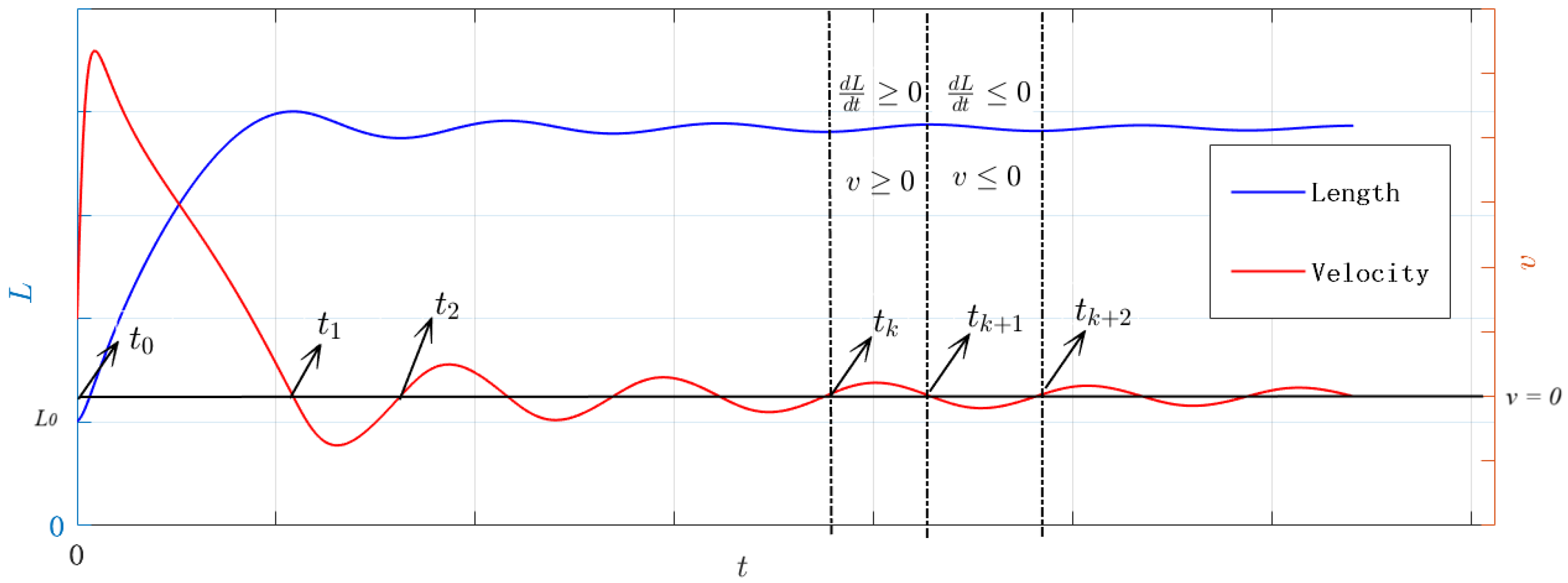
Figure 2 shows numerical solutions obtained for the water column length
L and the filling velocity
. It illustrates the time intervals where the filling velocity takes either positive or negative signs, i.e.,
or
. Since
is continuous over time, it reaches zero before switching sign (Bolzano’s theorem from Calculus [
1]). It is key to note the presence of the term
in order to solve the IVP (Equation (
10)). This term gives rise to two cases to consider:
and
.
Figure 2 also illustrates the oscillatory behaviour of
around zero. Thus, the IVP needs to be redefined as follows: instead of stating the problem for all
, consider splitting it into several sub-problems over time intervals of the form
. These intervals are to be determined by changes in the sign of
.
The hydraulic installation starts at (this yields ). Then, the value is the defined as . Under this condition, the sign of remains constnat for all (i.e., . Bolzano’s theorem states that, since v is continuous and given that v switches its sign, there has to be at least one value such that . The smallest value for is precisely ; i.e., .
When the IVP (
10) is solved on the interval
with initial conditions
and
, then the values
and
can be calculated.
Given that
is the smallest value such that
and
, then a value
can be defined as
. Furthermore, a new IVP can be defined on the interval
taking Equation (
10) and the initial conditions
and
.
These procedures are then repeated iteratively to construct a set of time subintervals
where
and
is defined as
. On the interval
an IVP is posed using Equation (
12) and initial conditions
and
.
Remark 1. By implicitly differentiating (13) with respect to t, Note that Equation (15) is trivially fulfilled when The solution is now presented for each of the two cases previously introduced.
3.2.1. Case on the Interval
Assuming that
holds for all
. Under this assumption, Equation (
10) takes the form
Substituting
into Equation (
16) and applying relation (
15), then
It follows that Equation (
16) becomes a linear first-order ODE for
w, given by
where
Since
, the functions
f and
g are continuous for all
L evaluated in the interval
. Therefore, Equation (
17) has a unique solution on
with initial condition
. This solution is given by [
25]:
with
and
Now, the computation of
and
is presented. It follows from direct calculation that:
so,
To compute
, it is necessary to define a family of special integrals whose values are expressed in terms of the lower incomplete gamma function [
26]. Let us define as
whose value is (see
Appendix A for more details):
for all
, and where
is the upper incomplete gamma function and
the gamma function [
26].
Now, by defining the integral
as
Since
, then
. Therefore, the binomial series
converge (see Reference [
25]) and
Therefore,
can be expressed as a binomial series of the form:
By substituting Equation (
30) into Equation (
27), we can express
in terms of the
as follows
3.2.2. Case on the Interval
In this case, let us assume that
for all
. Then, following the same reasoning as in
Section 3.2.1, it is possible to find that Equation (
10) can be rewritten as:
Introducing the substitution
, Equation (
32) takes the form of a linear first-order ordinary differential equation in terms of
w:
where
and
are the functions defined in (
18).
Proceeding in a manner analogous to the case
, with initial condition
, Equation (
33) admits a locally unique solution given by:
where
and,
Using reasoning analogous to that employed in the derivation of , it is possible to derive the expression for .
Then
This defines a family of special integrals related to the lower incomplete gamma functions whose value is given by (see
Appendix B):
for all
Using the power series expansion of the expression
, the integral
can be restated as:
3.3. Analytical Solution of , and in Terms of
This section presents the derivation of
,
y
as functions of the known quantity
w, which arises as the solution of the first-order differential Equations (
17) and (
33), corresponding to cases
and
, respectively.
3.3.1. Determination of
Since
, it follows that
. Explicitly,
3.3.2. Determination of
Since
, then
3.3.3. Determination for
Provided that
L has been determined from the auxiliary variable
w, the corresponding air pocket pressure is given by:
Accordingly, the complete solution of the 3 × 3 system (4)–(6) is described by Equations (
44)–(
46).
4. Verification of the Analytical Model
The analytical solution is validated by numerically solving the original system of Equations (4)–(6) and comparing the resulting solution with the analytical expressions given in Equations (
19)–(
21) and Equations (
34)–(
36) over their respective time intervals. For this comparison, the following parameter values were used:
m,
,
m,
s
2/m
−6,
m,
,
rad,
Pa, and
. The system was numerically solved using a fourth-order Runge–Kutta scheme.
4.1. Comparison Between the Integral-Form Analytical Solution and the Numerical Model
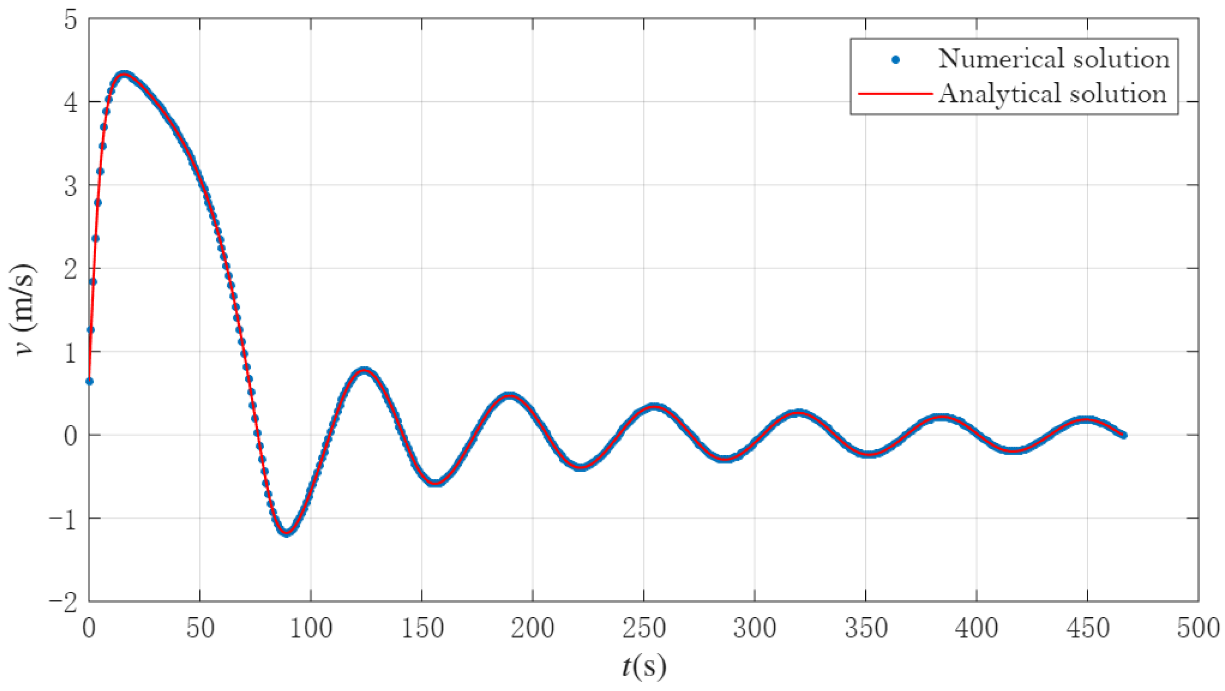
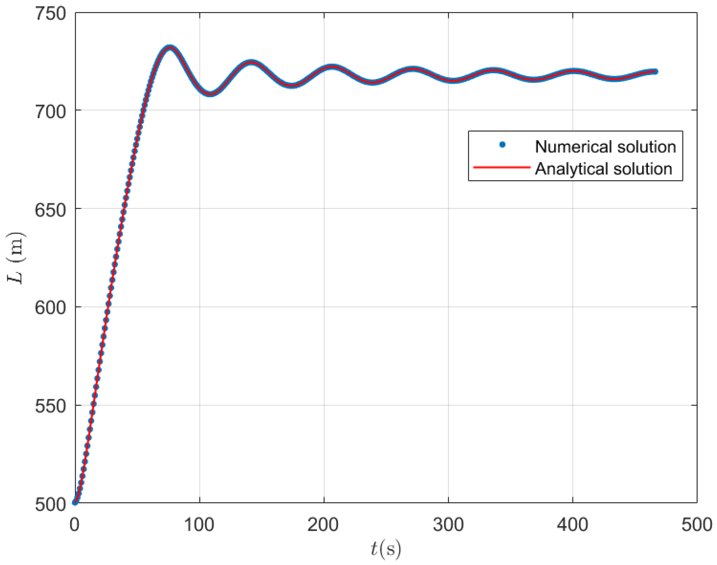
Figure 3,
Figure 4 and
Figure 5 depict these solutions, which were computed resolving numerically the integrals (
20), (
21), (
35) and (
36). It can be observed how both analytical and numerical solutions closely agree, supporting the analytical solution as a predictive tool for filling processes.
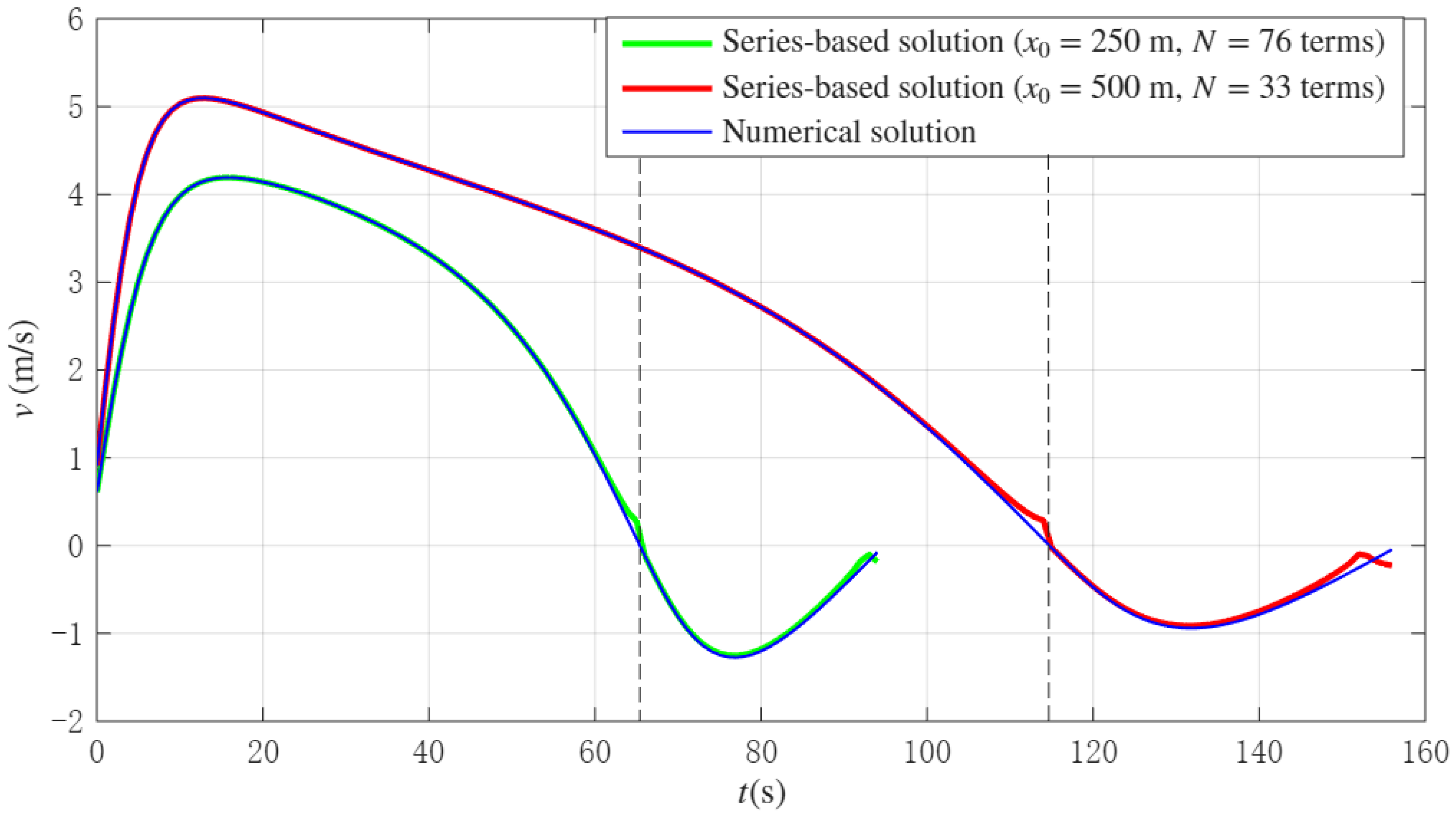
4.2. Convergence of the Series-Based Analytical Solution
Figure 6 presents the analytical solution explicitly defined by Equations (
31) and (
43) for the first two time intervals, corresponding respectively to the cases
and
. The same set of parameter values used in the previous section has been kept for consistency. With
terms in the series expansion, an average relative error of approximately 5% is observed when compared to the numerical solution. This result confirms the convergence and reliability of the series-based analytical solution relative to the numerical reference.
Figure 7 illustrates the behaviour of the series for two different values of
, while keeping all other parameters unchanged. For air pockets with lengths of
m and
m, it is observed that
and
terms are required, respectively, to achieve an average relative error of 5% in both cases. This indicates that the series converges more slowly as the initial size of the air pocket decreases (i.e., as the initial length of the water column
increases).
This behaviour can be explained by the fact that, with a smaller initial air pocket, the water column is longer, and the energy source needs to overcome less compressibility in the early stages. As a result, the velocity
v completes its first oscillation cycle in a shorter time. The shorter this time interval, the higher the curvature of the velocity function, and consequently, a greater number of terms is required in the series to accurately approximate the solution and ensure convergence [
27].
4.3. Comparison with Existing Experimental Measurements
In the study conducted by the authors [
10], a dataset comprising 12 experimental measurements of a start-up manoeuvre in a laboratory-scale facility is presented without expelled air, which was built in Polyvinyl chloride (PVC) [
3]. The hydraulic installation features an irregular pipeline profile with a total length of 7.6 m and a nominal diameter of 63 mm.
Figure 8 presents the schematic representation of the experimental facility [
10].
For the simulation of these scenarios, the following parameters were considered:
m,
mm (internal pipe diameter),
, and
rad.
Table 1 outlines the initial conditions of the experimental tests [
10], including the size of the entrapped air pockets (
) and the initial gauge pressure at the hydropneumatic tank (
).
The start-up process begins with the actuation of an electro-pneumatic ball valve, characterised by a discharge coefficient of
ms
2/m
−6 and an opening time of 0.2 s. The simulations were performed employing an absolute roughness (
mm) to represent the type of pipe. For calculating the friction factor, the Haaland formula was employed [
28,
29], as follows:
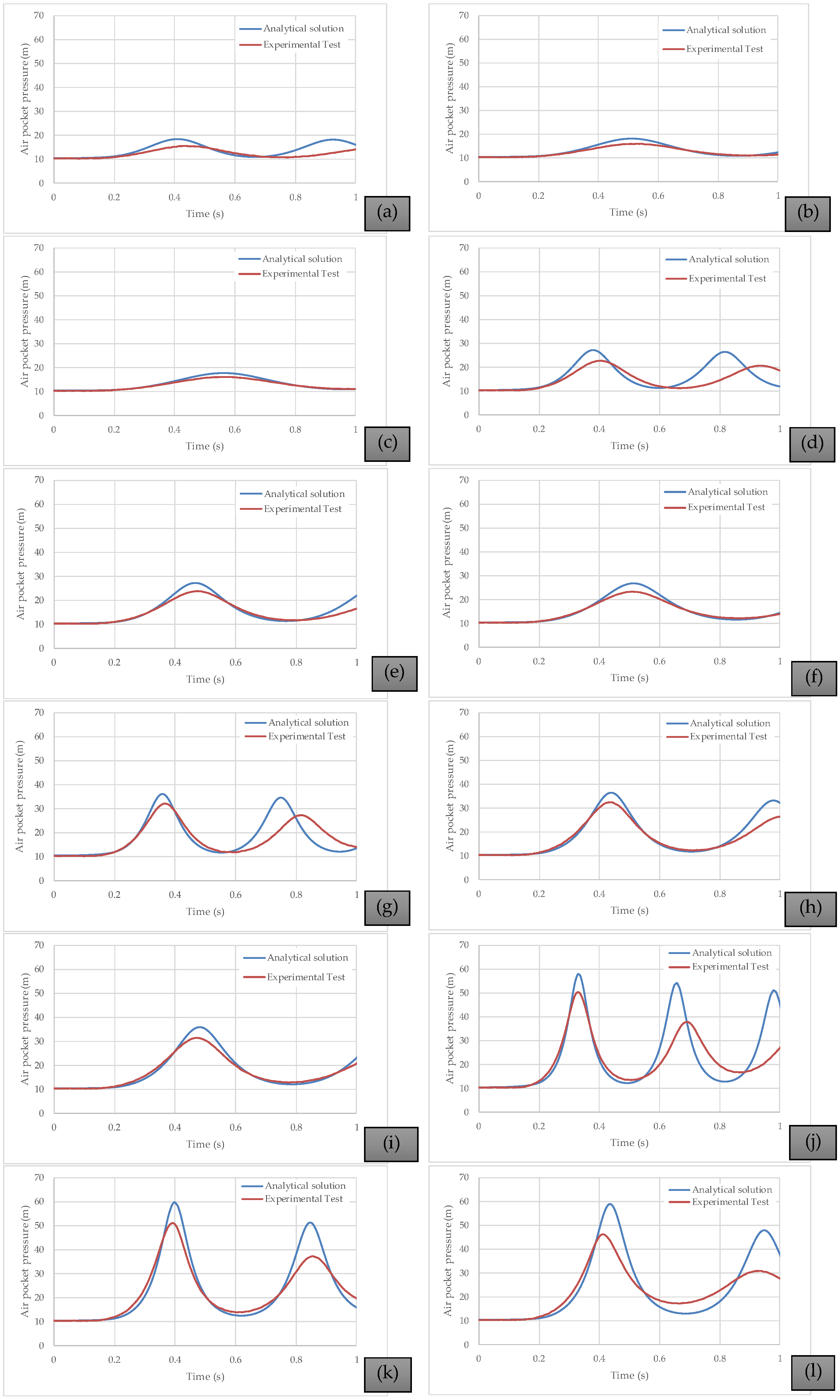
Figure 9 presents a comparison between the computed and measured air pocket pressures for the twelve experimental tests. The results indicate that the analytical solution is capable of accurately representing not only the peak values of the air pocket pressure, but also the associated oscillatory behaviour. It is a practical tool that water utilities can use to predict this manoeuvre. The analytical solution is suitable for representing the variation of the resistance coefficient, which was adequately modelled to reproduce the experimental measurements. In addition, the larger the internal pipe diameter, the higher the pressure developed within the air pocket. Finally, the discrepancies between the analytical solution and the experimental tests arise from the air–water interaction induced by the right pipe branch (
Figure 8), which generates an additional air pocket volume and consequently lower air pocket pressures. For capturing this interaction, the use of Computational Fluid Dynamics must be performed.
5. Conclusions
This work presents an analytical solution for describing the transient filling process in pressurised pipelines containing a trapped air pocket. The study addresses a complex physical phenomenon through a mathematical formulation that integrates fundamental physical laws, including momentum conservation, the geometric evolution of the air–water interface, and air compressibility governed by the polytropic law.
To obtain a piecewise analytical solution, the filling process is modelled by dividing the time domain into intervals defined by changes in the sign of the water front velocity. Within each interval, an initial value problem is formulated and solved by transforming the system of differential equations into a second-order autonomous equation, which is subsequently reduced to a first-order linear ordinary differential equation.
A more detailed solution involves a series-based formulation. In this approach, the general solution is expressed as a series of special integrals involving lower incomplete gamma functions, which allows for a suitable representation of the evolution of the water column length, water velocity, and air pocket pressure. This method preserves the physical structure of the model while enabling efficient numerical evaluation without relying exclusively on numerical solvers.
In an initial validation, the analytical solution was compared with numerical simulations based on Runge–Kutta methods for the same physical configuration, showing excellent agreement. This verification confirms the validity of the proposed approach throughout the different stages of the filling process, including flow reversal points.
The model was further validated using experimental data from controlled experimental facilities. The analytical solution successfully predicted the damped oscillatory behaviour observed in the tests.
Given its closed-form structure and demonstrated accuracy, the analytical solution has the potential to become a valuable tool for engineers involved in the design and operation of water-distribution networks, particularly during start-up procedures. It enables rapid estimation of critical conditions, such as maximum pressure within the air pocket, effective filling length, and the influence of parameters such as pipe slope, friction factor, or polytropic exponent.
Author Contributions
Conceptualisation, C.R.P.G., E.P.-B. and A.P.-V.; methodology, O.E.C.-H. and V.S.F.-M.; validation, O.E.C.-H. and V.S.F.-M.; formal analysis, C.R.P.G., E.P.-B. and A.P.-V.; investigation, C.R.P.G., E.P.-B. and A.P.-V.; writing—original draft preparation, O.E.C.-H., C.R.P.G., E.P.-B. and A.P.-V.; writing—review and editing, V.S.F.-M. All authors have read and agreed to the published version of the manuscript.
Funding
This research received no external funding.
Institutional Review Board Statement
Not applicable.
Informed Consent Statement
Not applicable.
Data Availability Statement
Data are contained within the article.
Acknowledgments
The second author (C.R.P.G.) thanks the Departamento de Matemática, Universidade Federal do Amazonas (UFAM), Brazil, for their hospitality during his postdoctoral stay.
Conflicts of Interest
The authors declare no conflicts of interest.
Abbreviations
The following abbreviations are used in this manuscript:
| ODE | Ordinary differential equation |
| RWC | Rigid water column |
| IVP | Initial value problem |
| Sup | Minimum upper bound of a set |
Appendix A. Expression of in Terms of the Normalised Lower Incomplete Gamma Function
We are interested in computing the integral
for all
, and expressing the result in terms of the normalised lower incomplete gamma function defined by
where
is the lower incomplete gamma function [
26]. The function
is real for positive and negative values of
a and
z.
We perform the substitution:
Using the standard incomplete gamma function
, we have:
By definition,
so we substitute this into the previous expression:
we obtain:
Appendix B. Expression of in Terms of the Normalised Lower Incomplete Gamma Function
We consider the integral
for all
, and we aim to express it in terms of the normalised lower incomplete gamma function
Let us define the change of variable:
This transforms the integral into:
From the identity
we substitute into the previous expression:
References
- Martin, C. Entrapped Air in Pipelines. In Proceedings of the Second International Conference on Pressure Surges, London, UK, 22–24 September 1976; pp. 15–28. [Google Scholar]
- Liou, C.P.; Hunt, W.A. Filling of pipelines with undulating elevation profiles. J. Hydraul. Eng. 1996, 122, 534–539. [Google Scholar] [CrossRef]
- Coronado-Hernández, E.; Besharat, M.; Fuertes-Miquel, V.S.; Ramos, H.M. Effect of a Commercial Air Valve on the Rapid Filling of a Single Pipeline: A Numerical and Experimental Analysis. Water 2019, 11, 1814. [Google Scholar] [CrossRef]
- Zhou, L.; Liu, D.; Karney, B. Investigation of hydraulic transients of two entrapped air pockets in a water pipeline. J. Hydraul. Eng. 2013, 139, 949–959. [Google Scholar] [CrossRef]
- Fuertes-Miquel, V.S.; Coronado-Hernández, O.E.; Mora-Melia, D.; Iglesias-Rey, P.L. Hydraulic modeling during filling and emptying processes in pressurized pipelines: A literature review. Urban Water J. 2019, 16, 299–311. [Google Scholar] [CrossRef]
- Huang, B.; Fan, M.; Liu, J.; Zhu, D.Z. CFD Simulation of Air–Water Interactions in Rapidly Filling Horizontal Pipe with Entrapped Air. In Proceedings of the World Environmental and Water Resources Congress 2021, Virtually, 7–11 June 2021; pp. 495–507. [Google Scholar] [CrossRef]
- Aguirre-Mendoza, A.M.; Paternina-Verona, D.A.; Oyuela, S.; Coronado-Hernández, O.E.; Besharat, M.; Fuertes-Miquel, V.S.; Iglesias-Rey, P.L.; Ramos, H.M. Effects of Orifice Sizes for Uncontrolled Filling Processes in Water Pipelines. Water 2022, 14, 888. [Google Scholar] [CrossRef]
- Martins, N.M.C.; Delgado, J.N.; Ramos, H.M.; Covas, D.I.C. Maximum transient pressures in a rapidly filling pipeline with entrapped air using a CFD model. J. Hydraul. Res. 2017, 55, 506–519. [Google Scholar] [CrossRef]
- Zhou, L.; Liu, D.Y.; Ou, C.-q. Simulation of Flow Transients in a Water Filling Pipe Containing Entrapped Air Pocket with VOF Model. Eng. Appl. Comput. Fluid Mech. 2011, 5, 127–140. [Google Scholar] [CrossRef]
- Paternina-Verona, D.A.; Coronado-Hernández, O.E.; Fuertes-Miquel, V.S.; Saba, M.; Ramos, H.M. Digital Twin Based on CFD Modelling for Analysis of Two-Phase Flows During Pipeline Filling–Emptying Procedures. Appl. Sci. 2025, 15, 2643. [Google Scholar] [CrossRef]
- Tijsseling, A.S.; Hou, Q.; Bozkuş, Z.; Laanearu, J. Improved One-Dimensional Models for Rapid Emptying and Filling of Pipelines. J. Press. Vessel Technol. 2015, 138, 031301. [Google Scholar] [CrossRef]
- Paternina-Verona, D.A.; Coronado-Hernández, O.E.; Aguirre-Mendoza, A.M.; Espinoza-Román, H.G.; Fuertes-Miquel, V.S. Three-Dimensional Simulation of Transient Flows during the Emptying of Pipes with Entrapped Air. J. Hydraul. Eng. 2023, 149, 04023007. [Google Scholar] [CrossRef]
- Zaitsev, V.F.; Polyanin, A.D. Handbook of Exact Solutions for Ordinary Differential Equations; Chapman and Hall/CRC: Boca Raton, FL, USA, 2002. [Google Scholar]
- Payares Guevara, C.R.; Patiño-Vanegas, A.; Pereira-Batista, E.; Coronado-Hernández, O.E.; Fuertes-Miquel, V.S. An Analytical Model for the Prediction of Emptying Processes in Single Water Pipelines. Appl. Sci. 2025, 15, 6000. [Google Scholar] [CrossRef]
- Berglund, E.Z.; Shafiee, M.E.; Xing, L.; Wen, J. Digital Twins for Water Distribution Systems. J. Water Resour. Plan. Manag. 2023, 149, 02523001. [Google Scholar] [CrossRef]
- Gino Ciliberti, F.; Berardi, L.; Laucelli, D.B.; David Ariza, A.; Vanessa Enriquez, L.; Giustolisi, O. From digital twin paradigm to digital water services. J. Hydroinform. 2023, 25, 2444–2459. [Google Scholar] [CrossRef]
- Brahmbhatt, P.; Maheshwari, A.; Gudi, R.D. Digital twin assisted decision support system for quality regulation and leak localization task in large-scale water distribution networks. Digit. Chem. Eng. 2023, 9, 100127. [Google Scholar] [CrossRef]
- Chaudhry, H. Application of lumped and distributed approaches for hydraulic transient analysis. In Proceedings of the International Congress on Cases and Accidents in Fluid Systems, ANAIS, Polytechnic University of Sao Paulo, Sao Paulo, Brazil, 16–17 January 1989. [Google Scholar]
- Abreu, J.; Cabrera, E.; Izquierdo, J.; García-Serra, J. Flow modeling in pressurized systems revisited. J. Hydraul. Eng. 1999, 125, 1154–1169. [Google Scholar] [CrossRef]
- Izquierdo, J.; Fuertes, V.S.; Cabrera, E.; Iglesias, P.L.; Garcia-Serra, J. Pipeline start-up with entrapped air. J. Hydraul. Res. 1999, 37, 579–590. [Google Scholar] [CrossRef]
- Laanearu, J.; Annus, I.; Koppel, T.; Bergant, A.; Vučković, S.; Hou, Q.; Van’t Westende, J. Emptying of large-scale pipeline by pressurized air. J. Hydraul. Eng. 2012, 138, 1090–1100. [Google Scholar] [CrossRef]
- American Water Works Association. Air-Release, Air/Vacuum, and Combination Air Valves: M51; American Water Works Association: Denver, CO, USA, 2001; Volume 51. [Google Scholar]
- Bonilla-Correa, D.M.; Coronado-Hernández, O.E.; Fuertes-Miquel, V.S.; Besharat, M.; Ramos, H.M. Application of Newton-Raphson Method for Computing the Final Air-Water Interface Location in a Pipe Water Filling. Water 2023, 15, 1304. [Google Scholar] [CrossRef]
- Braun, M. Differential Equations and Their Applications, Short version; Springer: Berlin/Heidelberg, Germany, 1978. [Google Scholar]
- Apostol, T.M. Calculus. Vol. I: One-Variable Calculus, with an Introduction to Linear Algebra, 2nd ed.; John Wiley & Sons: New York, NY, USA, 1967; pp. 441–444. [Google Scholar]
- Paris, R.B. Incomplete gamma and related functions. In NIST Handbook of Mathematical Functions; U.S. Dept. Commerce: Washington, DC, USA, 2010; pp. 175–192. [Google Scholar]
- Boyd, J.P. Chebyshev and Fourier Spectral Methods, 2nd ed.; Dover Publications: New York, NY, USA, 2001. [Google Scholar]
- Muzzo, L.E.; Matoba, G.K.; Frölén Ribeiro, L. Uncertainty of pipe flow friction factor equations. Mech. Res. Commun. 2021, 116, 103764. [Google Scholar] [CrossRef]
- Haaland, S.E. Simple and Explicit Formulas for the Friction Factor in Turbulent Pipe Flow. J. Fluids Eng. 1983, 105, 89–90. [Google Scholar] [CrossRef]
| Disclaimer/Publisher’s Note: The statements, opinions and data contained in all publications are solely those of the individual author(s) and contributor(s) and not of MDPI and/or the editor(s). MDPI and/or the editor(s) disclaim responsibility for any injury to people or property resulting from any ideas, methods, instructions or products referred to in the content. |
© 2025 by the authors. Licensee MDPI, Basel, Switzerland. This article is an open access article distributed under the terms and conditions of the Creative Commons Attribution (CC BY) license (https://creativecommons.org/licenses/by/4.0/).
