Article

Improved Box Models for Newtonian and Power-Law Viscous Gravity Currents in Rectangular and Axisymmetric Geometries

Department Computer Science, Technion, Haifa 320000, Israel
Fluids 2025, 10(8), 207; https://doi.org/10.3390/fluids10080207
Submission received: 9 July 2025 / Revised: 4 August 2025 / Accepted: 5 August 2025 / Published: 8 August 2025
(This article belongs to the Section Geophysical and Environmental Fluid Mechanics)

Abstract

We consider the flow of gravity currents of Newtonian and power-law non-Newtonian viscous fluids, injected over a horizontal boundary in rectangular and cylindrical (axisymmetric) systems. We focus on some novel box model (BM) predictions. Previously published theoretical studies consider a power-law volume V = q t α (influx rate Θ = α q t α 1 ) where q > 0 and α 0 are constants and t is time. The lubrication simplification equations predict a self-similar flow: the propagation is K L t β , and the height (thickness) profile is determined by a second-order ODE in the reduced length ξ [ 0 , 1 ] . The predicted β and K L are in good agreement with laboratory data. Previous studies reported that a basic BM predicts K 1 t β propagation with the same β as the lubrication model, but the discrepancy between K 1 and K L is in general not small. This work points out two inconsistencies of the basic BM with the physical system and presents an improved, more consistent, BM prediction, K 2 t β . We show that K 2 is in general more accurate than K 1 (including in comparison with experimental data). Next, we consider a general influx Θ ( t ) (not a power law). We demonstrate that the BM provides a simple and flexible framework of initial-value time-dependent ODEs, though for such systems the lubrication theory lacks analytical reduction and requires numerical solution of a non-linear PDE (in time and length).

1. Introduction

Gravity current (GC) is a generic name for the buoyancy-driven flow of a fluid of one density, ρ , into an ambient fluid of a different density, ρ a , mostly in the horizontal direction x (to be distinguished from the mostly vertical buoyancy-driven flows called plumes); see Ref. [1] and the references therein. The driving buoyancy mechanism is a result of the fact that in a thin layer the vertical acceleration is negligible, and hence the pressure fields are hydrostatic, p j ρ j g z ; this produce a horizontal pressure gradient g = | ρ / ρ a 1 | g , where g is the gravitational acceleration, z is the vertical upward coordinate, j denotes the ambient and current, and g is the reduced gravity. The buoyancy is balanced by either inertial or viscous effects. Here we consider the so-called viscous GCs, dominated by a buoyancy–viscous dynamic balance and relevant to flows at a small Reynolds number. Viscous GCs have numerous applications in nature and industry, for example, oil spills on the sea, lava, mudslides (Refs. [2,3], and soft plastics [4]). Early investigations were concerned with the flow of Newtonian fluids (e.g., [5,6]), and more recent studies have focused attention on the more complex non-Newtonian fluids, in particular with power-law viscosity ( shear ) n 1 , where n is the behavior index—see (8)—and n = 1 is for a Newtonian fluid (e.g., [7,8,9,10]).
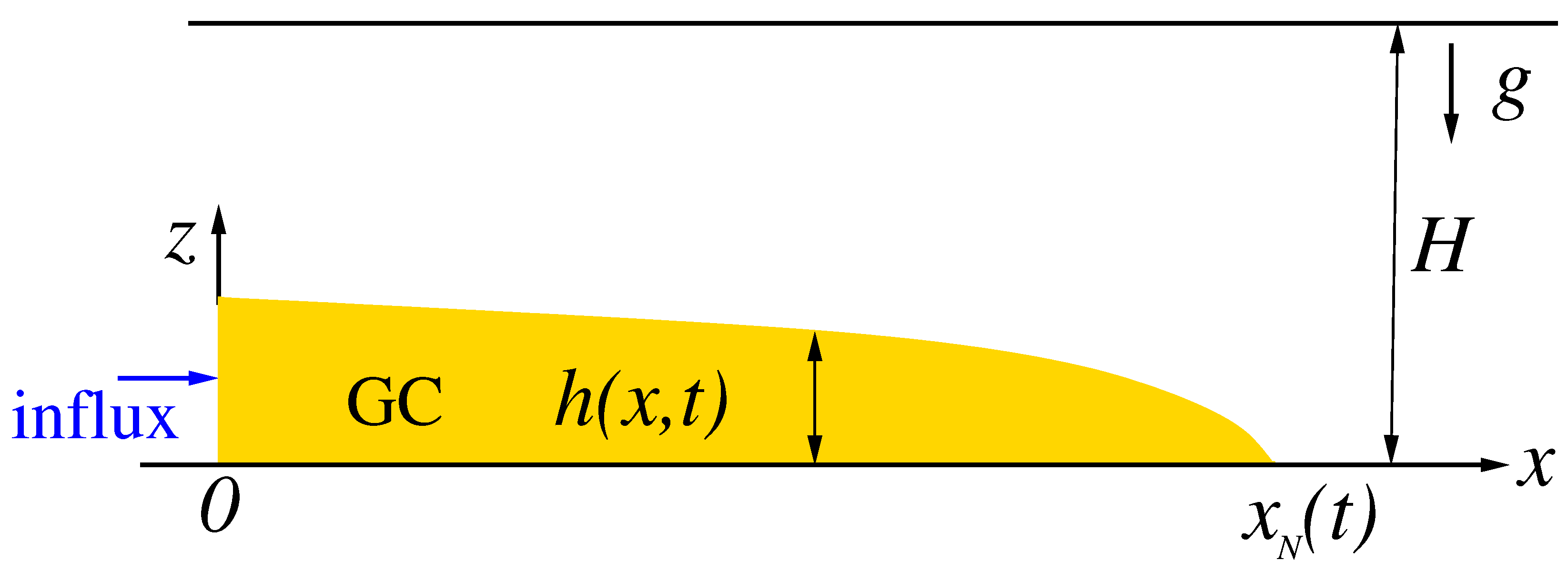
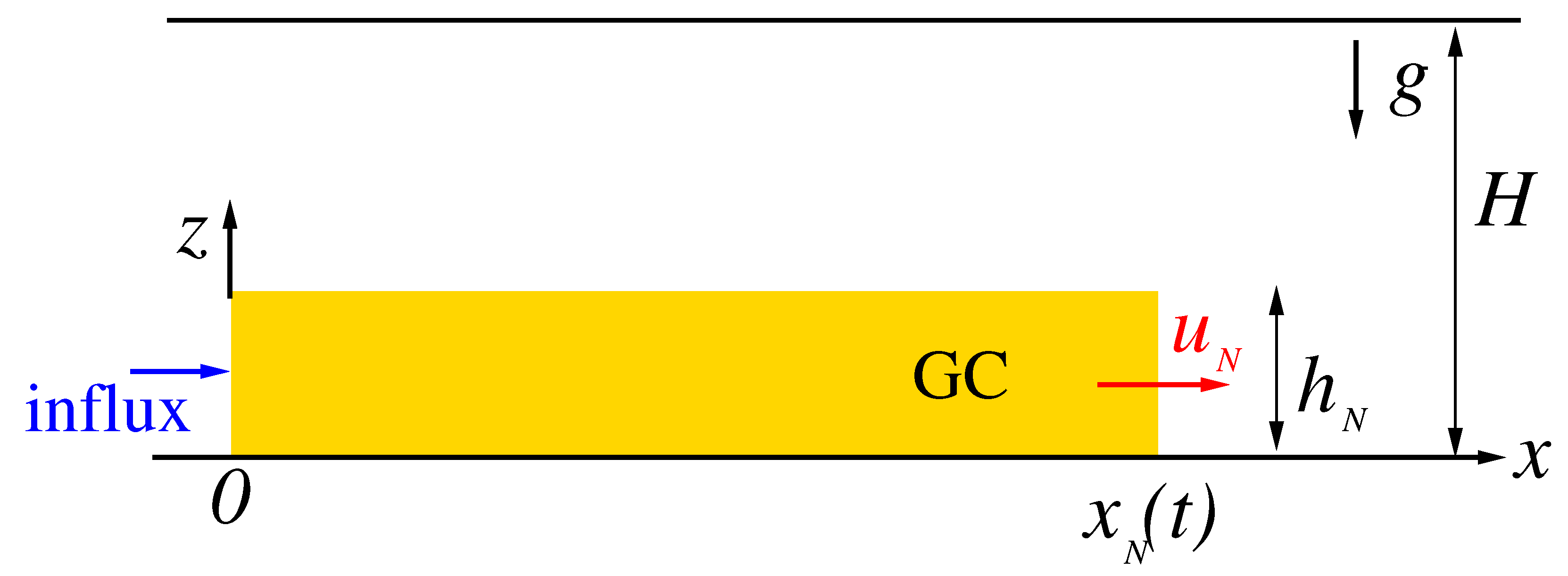
The theoretical frameworks were the following: (1) the thin-layer lubrication model (Refs. [5,6,8,10]), which requires the solution of a partial differential equation for the interface h ( x , t ) (x is the direction of propagation and t is time); (2) the box model, abbreviated as BM (Refs. [1,11,12,13]), postulates a horizontal interface h ( t ) and requires the solution of simple initial-value ordinary differential equations; see Figure 1.
The prototype GC in the published studies is of volume q t α , α 0 , where t is time. Such systems provide a triple advantage. First, the lubrication model is amenable to a similarity transformation that reduces the problem to requiring the solution of an ordinary differential equation. Second, the BM formulation is reduced to some simple algebraic formulas. Third, both models predict propagation of the form x N ( t ) = K t β , with exactly the same β (a simple dimensionless function of α , n and the geometry of the rectangular two-dimensional (2D) or cylindrical axisymmetric (AXI)). These predictions are very convenient for verification and empirical corrections by laboratory experiments. In the typical laboratory experiment (e.g., Refs. [6,10,11,13,14]) the viscous fluid (of known properties) is either released from a lock ( α = 0 case) or slowly injected from a controlled source ( α > 0 case) over a smooth horizontal surface (the bottom). After a while, a clear-cut thin layer (the GC) will spread out. The shape of the inlet and the lateral walls determines if the spreading is 2D or AXI. The edge of the current, x N ( t ) (or r N ( t ) ) , is recorded. These measurements are then curve-fitted to the expected K t β form, and they provide the data β e x p and K e x p (within some ± error). In general, the experiments (1) confirmed the predicted β , within a small error, (2) displayed fair agreement with the K predicted by the lubrication model, but (3) revealed some notable discrepancies (typically 25% overprediction) with the values of K predicted by the BM (more details will be given below). The reasons for these discrepancies of the BM have not received much attention, to our knowledge, and no attempts at theoretical improvement of the BM have been made. The fact that the BM predicts exactly the same β as the lubrication model but significantly overpredicts K is intriguing. Dimensional analysis (Refs. [15,16]) indicates the same time scaling for the box and lubrication models, but this does not warrant the existence of a similarity solution. We note that K is a dimensional constant, and upon a proper scaling it can be reduced to a dimensionless coefficient κ of order unity, which is a function of α , n and the geometry.
This gap of knowledge has motivated the present work: a revisit of the BM, with the aim of improving the predictions. In this context, we emphasize that the BM has merits, which endow this revisit with practical benefits. First, as compared to the lubrication model, the physical balances governing the BM are significantly more transparent and are expressed in simple mathematical formulas, thus providing sharper insights and faster results. Second, when the influx is not a time power (a relevant practical situation), the lubrication model requires a numerical solution of a PDE with initial and non-trivial boundary conditions, while the BM predictions can be obtained by a simple integration of initial-value ODEs. The analysis is complicated by the fact that a convenient scaling of the variables is not available for a GC sustained by a general influx function. This suggests that the BM is a valuable ingredient in the toolkit for the analysis of GC systems.
The present work makes some progress. We must keep in mind that the BM is, essentially, a bold approximation based on instantaneous balances of volume and forces (buoyancy and viscous) over the entire mass of the GC. (This method of analysis is also referred to as “momentum integral;” see Ref. [17]). The local details of the flow field are replaced by some plausible simplification formulas, which allow easy mathematical manipulations, particularly easy integration over the volume. The accuracy of the results cannot be guaranteed a priori, and therefore BM solutions can be endorsed only after systematic comparisons with more rigorous solutions and/or data (experiments, Navier–Stokes simulations). The similarity solution of the lubrication model is therefore a very convenient benchmark for the BM.
Moreover, the choice of closures/simplifications used in the BM allows for some flexibility. The major assumption of a horizontal interface is a fixed feature, but the BM involves some assumptions about the velocity profile in the layer. We argue that these assumptions did not receive sufficient attention in previous works and suggest that a more careful approach to this issue may improve the accuracy of K. We show that the apparently accepted BM formulation (which we call basic) uses some simplifications for the velocity profiles that are not fully consistent with the physical system, in general. In hindsight, these can be called over-simplifications. We introduce an improved formulation that removes these inconsistencies within an insignificant mathematical complication. Comparisons with the lubrication theory and with data support this version of the BM (which we call “improved”). In other words, for GCs of volume V = q t α , we can calculate and compare the dimensionless κ 1 , κ 2 , κ L of the basic box, improved box, and lubrication models; and then we also compare them with the experimental κ e x p . We extend the BM formulation to the general influx and illustrate the application. Overall, the results are satisfactory and can be recommended for further use.
The paper is organized as follows. The major part of the analysis is concerned with power-law volume V = q t α because, for such systems, similarity solutions are available for reliable comparisons. The BM predictions are developed for the basic and improved versions, and then they are compared with the similarity solution for the rectangular two-dimensional (2D) and cylindrical axisymmetric (AXI) geometries, in Section 2 and Section 3, respectively. A comparison with data from the literature is presented in Section 4. In Section 5 the BM for the general time-dependent influx is formulated and tested. Concluding remarks are made in Section 6. Appendix A presents the derivation of the improved shear formula, Appendix B gives some suggestions for scaling, and Appendix C summarizes the method for obtaining the lubrication model coefficient κ L .
Figure 1. Sketch of the box model (BM) system. The volume (per unit width) is V = q t α . In the self similar flow, x N = K t β . In the axisymmetric geometry, r replaces x and V is per radian. α , β , K are constants.
Fluids 10 00207 g001

2. Two-Dimensional Flow

The basic simplification of the BM is that the dense fluid is contained in a rectangular box. The source is at x = 0 . The interface of the GC is horizontal, i.e., h ( x , t ) = h N ( t ) , with a vertical jump at the nose, see Figure 1. The subscript N denotes the nose of the GC. The velocity of the fluid in the box is u ( x , t ) . In the realistic viscous GC, the velocity is z dependent and subject to the no-slip condition at the bottom z = 0 . The BM u ( x , t ) must be interpreted as the depth-averaged velocity. (The no-slip condition will enter the balances as a friction force.) We assume a deep ambient H h and hence the effect of the return flow is negligible, and there is no shear at the interface. The balances are performed per unit width.
The volume of the injected fluid is V = q t α , q > 0 , α 0 . α = 0 represents a GC of fixed volume q. This time-dependency of V suggests a propagation of the form
x N ( t ) = K t β , u N = β K t β 1 , h = h N ( t ) ,
where K and β are positive constants. The major task is to determine K and β for given influx conditions and given fluid. We use dimensional variables unless stated otherwise.
Consider the kinematic balances. The constant x-independent h = h N has two important implications. First, total volume conservation x N h N = K t β h N = q t α yields
h N = q K t α β .
Second, the continuity equation h t + ( u h ) x = 0 imposes that u ( x , t ) is a linear function of x. This we express as
u ( x , t ) = u N ( t ) U ( ξ ) = β K U ( ξ ) t β 1 ,
where
ξ = x / x N ( t ) , U ( 1 ) = 1 ,
and we keep in mind that U ( ξ ) is of the form c 1 + c 2 ξ . Moreover, we note that c 2 ( d h N / d t ) (the vertical velocity of the interface), and hence, in general, this coefficient is non-zero.
The dynamic balance is between the forces acting on the entire GC in the box from x = 0 to x N . This is expressed as
F V = F B ,
where the buoyancy force is given by
F B = ( 1 / 2 ) ρ g h N 2 ,
and the viscous force due to the shear τ at the bottom is provided by
F V = 0 x N τ ( x , t ) d x = x N 0 1 τ ( ξ , t ) d ξ .
The calculation of τ at the bottom is as follows. First, because this is a viscous effect, we must take into consideration the shear in the realistic u ^ ( x , z , t ) velocity in the layer. We recall that the BM velocity is the depth-averaged u ( x , t ) = ( 1 / h ) 0 h u ^ ( x , z , t ) d z where the “hat” (^) is used to emphasize the physical, not averaged velocity. Second, we consider the GC to obey the power-law relationship (see Ref. [18]) for the dynamic and kinematic viscosities as follows
μ = m u ^ z n 1 , ν = m / ρ ,
where m is the consistency index and n is the behavior index (or exponent). The cgs dimension of ν is cm 2 s n 2 . A fluid is shear-thinning (pseudoplastic) if n < 1 , shear-thickening (dilatant) if n > 1 , and Newtonian if n = 1 (in this case, m = μ , the standard dynamic viscosity of the fluid and ν is the standard kinematic viscosity coefficient). Third, we recall that at the bottom z = 0 , τ = ν ρ [ ( u ^ / z ) 0 ] n . Finally, we seek an approximation to ( u ^ / z ) 0 in terms of the variables of the BM. We argue (see Ref. [14]) that the shear at z = 0 is proportional to the local slope u / h (the ratio of the depth-averaged velocity to the thickness of the layer). Taking these points into account, and using h = h N , we express the BM approximation of the shear stress at the bottom
τ ( x , t ) = ν ρ γ u ( x , t ) h N n , or τ ( ξ , t ) = ν ρ γ u N ( t ) h N ( t ) U ( ξ ) n ,
where (3) and (4) were used and γ is a constant. In other words, in the BM balances the shear at the bottom is approximated by γ u ( x , t ) / h N ( t ) , where γ is a constant, to be specified later. Order-of-magnitude arguments (Refs. [6,14]) suggest that γ is of the order of unity.
Using (9) the force balance (5)–(7) reads
ρ ν u N ( t ) h N ( t ) n x N ( t ) [ γ n I ] = ( 1 / 2 ) ρ g h N 2 ( t ) ,
where
I = 0 1 U n ( ξ ) d ξ .
We substitute (1) and (2) into (10), and after some algebra find that the force balance is fulfilled when
β = [ ( n + 2 ) α + n ] / ( 2 n + 3 ) ,
K = G q n + 2 1 / ( 2 n + 3 ) Ω κ ,
where
G = g / ν ,
Ω = ( 1 2 β n ) 1 / ( 2 n + 3 ) ,
κ = γ n I 1 / ( 2 n + 3 ) .
We conclude that the time-power β of the propagation is unique. The coefficient K is a product of the following: (a) a dimensional (scale) term which contains G and q; (b) a unique dimensionless term Ω which depends on β (or α ); (c) the ambiguous dimensionless coefficient κ .
The coefficient κ is ambiguous because it depends on three unspecified constants: the coefficient γ for the shear, and the coefficients c 1 and c 2 for the horizontal velocity profile U ( ξ ) . The guidelines for the needed closures are that γ is of the order of 1, U ( 1 ) = 1 , and that in general c 2 is non-zero. We consider two practical methods for finalizing the calculation of κ , as follows:
(1) The basic approach, which has been used for the BM calculation of K in previous investigations (without exception, to our knowledge), employs the simplest plausible correlation that satisfies the abovementioned guidelines. In this case, the choice is γ = 1 and c 1 = 0 , i.e., U ( ξ ) = ξ . Using (11), we obtain
κ = κ 1 = ( n + 1 ) 1 / ( 2 n + 3 ) .
This closure method is somewhat arbitrary. There is no a priori justification why other constants, e.g., γ = 1.5 and c 1 = 0.1 , should not be used. Conversely, γ and c 1 can be considered adjustable parameters of this model. The reliability of the predicted κ 1 is debatable.
(2) The improved approach suggests to use additional consistent information, if it is expected to “correct” the previous choice. First, we note that the choice U = ξ imposes zero influx at x = 0 , which is inconsistent with the α > 0 systems. The consistent influx velocity is given by
u ( x = 0 , t ) = α q t α 1 / h N = α K t β 1 ,
where (1) and (2) were used. The improved velocity profile is therefore
U ( ξ ) = α / β + ( 1 α / β ) ξ ,
and hence
I = I 2 = 1 ( α / β ) n + 1 ( n + 1 ) ( 1 α / β ) ( α / β 1 ) ,
and I 2 = 1 when α / β = 1 .
Next, we recall that γ = 1 is just a guess based on an order-of-magnitude estimate (Ref. [14]) of the ratio between u ^ / z at the bottom and the local slope u / h (here u is the depth-averaged velocity). We look at a physical solution for more guidance. The lubrication theory solution for a GC, see Appendix A, provides a rigorous, more realistic, result for this connection, given by
γ = γ 2 = 2 + 1 / n .
With these new estimates, we obtain
κ = κ 2 = ( 2 + 1 / n ) n I 2 1 / ( 2 n + 3 ) .
We conclude that the closures c 1 = 0 and γ = 1 are over-simplifications. The use of other values improves the connection of the model with the physical system, without affecting the mathematical simplicity of the formulation. Moreover, the present model is unique. The clear-cut physical arguments for the setting of U ( ξ ) by (19) and γ = γ 2 render the value of κ 2 self-contained, with no adjustable parameters.
We note that the factor γ 2 n / ( 2 n + 3 ) decreases with n from 1 to 2 1 / 2 = 0.71 , see Figure 2. This represents the contribution of the z / h -profile of the velocity to κ 2 . The simple change of the linear-profile over-simplification γ = 1 for the more physical parabolic shape is already a fairly significant improvement of the over-predictions of the basic BM, even for Newtonian fluids n = 1 . This correction is slightly less significant for the AXI system. We also note the non-linear behavior of the system. The change to parabolic profile yields a strong increase in τ (factor 3 for the Newtonian n = 1 ), but the influence on κ is only a few percent (This illustrates why a BM may give fairly good predictions in spite of bold simplifications. Unfortunately, this argument may also work in the opposite direction). The coefficient c 1 = 0 of the basic model is recovered for α = 0 ; in this case, the difference between κ 1 and κ 2 is only due to γ 2 .
Although we have invested more physical considerations into the derivation of κ 2 , there is no guarantee for a more accurate solution in general. The stringent test involves a comparison with a more rigorous solution. The lubrication theory analysis of the GC (see Ref. [8]) provides the similarity solution
x N ( t ) = G q n + 2 1 / ( 2 n + 3 ) Ω κ L t β ,
where κ L is obtained numerically. The important point is that the BM and the rigorous solution are in full agreement concerning the value of β , see (12), and the form of the prefactor of t β ; the only difference is in the value of the coefficient κ (which is expected to be of the order 1). The coefficient κ L is a by-product of the solution of a second-order differential equation for the ξ -dependency profile of the height of the GC, for a given pair of α and n (some details are given in Appendix C). For comparison, we fix the values of q , n , ν , g and α .
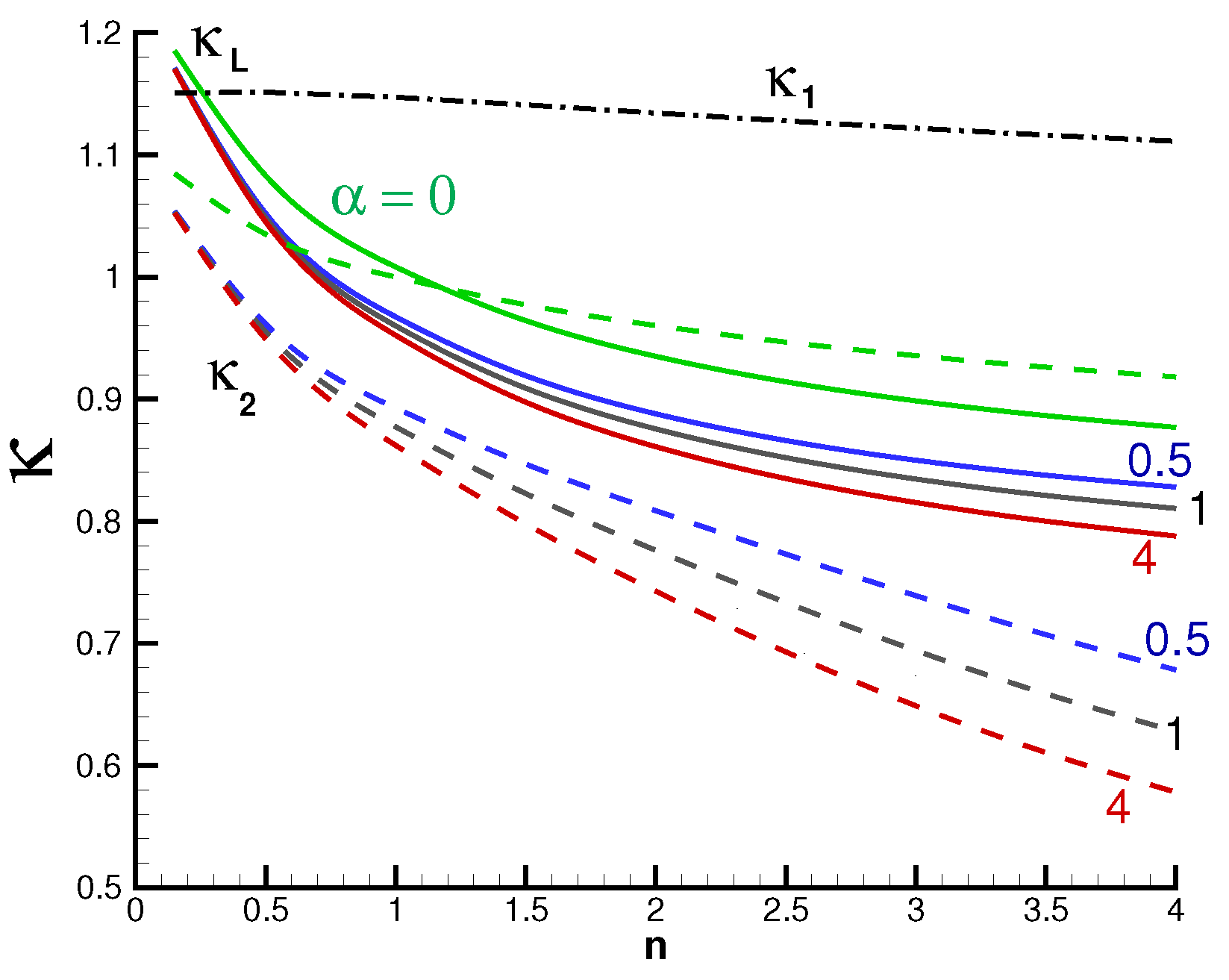
Figure 3 shows κ L , κ 1 and κ 2 . We observe that κ 2 reproduces well the trends of κ L with n and α , and in general, the discrepancies are smaller than for κ 1 .
Figure 2. γ 2 s vs. n. Blue line s = n / ( 2 n + 3 ) for 2D, red line s = n ( 3 n + 5 ) for AXI. Also shown the asymptotes 2 1 / 2 and 2 1 / 3 , respectively.
Fluids 10 00207 g002
Figure 3. Two-dimensional system. κ L (solid line) and κ 2 (dashed line) vs. n for various α = 0 , 0.5 , 1 , 4 , and κ 1 (dashdot line, independent of α ).
Fluids 10 00207 g003
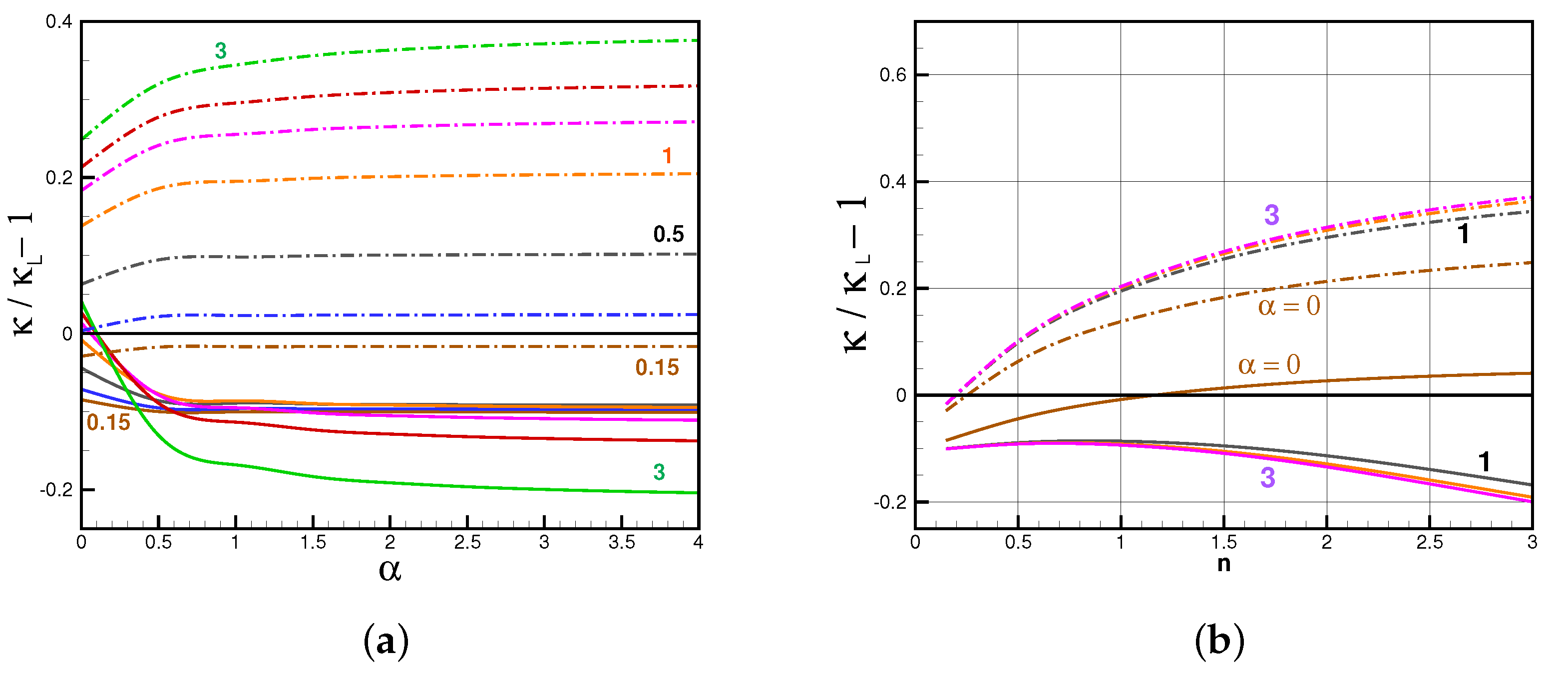
Figure 4 display the relative differences of κ 1 and κ 2 from κ L . For each value of n, the error (absolute value) increases strongly from α = 0 to α = 1.5 (approximately); thereafter, the increase with α is mild.
We note that Ref. [11] presented comparisons of Ω κ (called k v in that paper) for the basic BM and lubrication model for 0.15 n 1 and 0 α 3 , Figure 9 of that paper. The novelty here is the introduction of the improved BM; the question is whether κ 2 is a more reliable result than κ 1 . Figure 4 indicates that the answer is in the affirmative.
Figure 4. BM 2D, results of κ 1 / κ L 1 (dash dot line) and κ 2 / κ L 1 (solid line). (a) vs. α for various n = 0.15, 0.5, 1, 1.5, 2, 3; (b) vs. n for various α = 0 , 1 , 2 , 3 .
Fluids 10 00207 g004

3. Axisymmetric Flow

The basic simplification of the BM is that the dense fluid is contained in a cylinder box. The source is at the axis r = 0 . The interface of the GC is horizontal, i.e., h ( r , t ) = h N ( t ) , see Figure 1. The balances are performed per radian (i.e., we omit the coefficient 2 π ) .
The volume of the injected fluid is V = q t α , which suggests a propagation of the form
r N ( t ) = K t β , u N = β K t β 1 , h = h N ( t ) ,
where K and β are positive constants.
Consider the kinematic balances. The constant r-independent h = h N has two important implications. First, total volume conservation ( 1 / 2 ) r N 2 h N = ( 1 / 2 ) K 2 t 2 β h N = q t α yields
h N = 2 q K 2 t α 2 β .
Second, the continuity equation r h t + ( r u h ) r = 0 imposes that u ( r , t ) is of the form c 1 r + c 2 / r . This we express as
u ( r , t ) = u N ( t ) U ( ξ ) = β K U ( ξ ) t β 1 ,
where
ξ = r / r N ( t ) , U ( 1 ) = 1 ,
and we keep in mind that U ( ξ ) is of the form c 1 ξ + c 2 / ξ .
The dynamic balance is between the forces acting on the entire GC in the cylinder box from 0 to r N . This is expressed, again, as
F V = F B ,
where the buoyancy force is given by
F B = ( 1 / 2 ) ρ g h N 2 r N ,
and the viscous force due to the shear at the bottom is calculated by
F V = 0 r N τ ( r , t ) r d r = r N 2 0 1 τ ( ξ , t ) ξ d ξ .
The dynamic and kinematic viscosities of the current are as discussed in the previous section; upon replacing x by r, the BM simplification is expressed as
τ ( r , t ) = ν ρ γ u ( r , t ) h N n , or τ ( ξ , t ) = ν ρ γ u N ( t ) h N ( t ) U ( ξ ) n ,
where γ is a constant of the order of unity.
Using (31) the force balance reads
ρ ν u N ( t ) h N ( t ) n r N 2 ( t ) [ γ n I ] = ( 1 / 2 ) ρ g h N 2 ( t ) r N ( t ) ,
where
I = 0 1 U n ( ξ ) ξ d ξ .
We substitute (24) and (25) into (32), and after some algebra find that the force balance is fulfilled when
β = [ ( n + 2 ) α + n ] / ( 3 n + 5 ) ,
K = G q n + 2 1 / ( 3 n + 5 ) Ω κ ,
where
Ω = ( 2 ( n + 1 ) β n ) 1 / ( 3 n + 5 ) ,
κ = γ n I 1 / ( 3 n + 5 ) .
We conclude that the time-power β of the propagation is unique, but the prefactor K contains the ambiguous dimensionless coefficient κ . As in the 2D case, we consider two closure assumptions.
(1) The basic approach employs γ = 1 and U ( ξ ) = ξ . Consequently, using (33), we obtain
κ = κ 1 = ( n + 2 ) 1 / ( 3 n + 5 ) .
(2) The improved approach. The choice U = ξ implies unrealistic influx at (and near) the axis r = 0 when α > 0 . We noticed that the continuity equation admits a solution of the form c 1 r + c 2 / r . The influx velocity is given by
[ r u ( r , t ) ] r = 0 + = α q t α 1 / h N = ( 1 / 2 ) α K 2 t 2 β 1 .
Using r = ξ K t β , (24)–(25), and some algebra, we find that the improved radial velocity, which satisfies the boundary conditions at r N and 0 + is given by
u ( r , t ) = β K t β 1 ( 1 ( α / ( 2 β ) ) ξ + ( α / ( 2 β ) ) / ξ = u N ( 1 ( α / ( 2 β ) ) ξ + ( α / ( 2 β ) ) / ξ .
The improved velocity profile is
U ( ξ ) = ( 1 ( α / ( 2 β ) ) ξ + ( α / ( 2 β ) ) / ξ ,
and hence
I = I 2 = ξ 0 1 ( 1 ( α / ( 2 β ) ) ξ + ( α / ( 2 β ) ) / ξ n ξ d ξ .
The small ξ 0 (we use 0.05) mimics the finite radius of a realistic source, and is needed to avoid the singularity at the axis, and then the numerical evaluation of I 2 is straightforward. The improved γ is provided by (21) by the same argument. With these new estimates, we obtain
κ = κ 2 = ( 2 + 1 / n ) n I 2 1 / ( 3 n + 5 ) .
The deficiencies of the basic model and advantages of the improved model outlined for the 2D case (Section 2) carry over to the AXI system.
The stringent test is a comparison with the lubrication theory (see Refs. [10,13]), which provides the similarity solution
r N ( t ) = G q n + 2 1 / ( 3 n + 5 ) Ω κ L t β ,
where κ L is obtained numerically (see Appendix C). The important point is that the BM and the rigorous solution are in full agreement concerning the value of β , see (34), and prefactor of t β ; the only difference is in the coefficient κ .
Figure 5 shows the behavior of κ 1 , κ 2 and κ L as functions of n, and Figure 6 displays the relative differences of κ 1 and κ 2 from κ L . The basic κ 1 is a slightly more accurate approximation for n < 0.5 , but for larger n the error of the improved κ 2 is about two times smaller.
We note that [13] presented values of κ 1 / κ L 1 for the basic BM and lubrication model for 0.1 n 2 and 0 α 2 (Figure 2 in that paper). The novelty here is the introduction of the improved BM; the question is whether κ 2 is more accurate than κ 1 . As in the 2D case, the answer is in the affirmative.
Figure 5. AXI system. κ L (solid line) and κ 2 (dashed line) vs. n for various α = 0 , 0.5 , 1 , 4 , and κ 1 (dashdot line, independent of α ).
Fluids 10 00207 g005
Figure 6. BM AXI, results of κ 1 / κ L 1 (dash-dot line) and κ 2 / κ L 1 (solid line): (a) vs. α for various n = 0.15, 0.5, 1, 1.5, 2, 3; (b) as a function of n for various α = 0 , 1 , 2 , 3 .
Fluids 10 00207 g006

4. Comparison with Data

Previous investigations (e.g., [6,10,11,13]) report comparisons of experiments with similarity solutions of the lubrication theory model, in particular for α = 0 (fixed volume) and α = 1 (constant influx). In general, there is very good agreement for the time-power β . Since the BM and the lubrication theory predict the same value of β , this good agreement with data carries over to the BM. This has been noted in the published literature in the context of the basic BM.
In general, the comparisons also found good agreement of the measured K with the lubrication-theory predictions. In dimensionless form, there is good agreement between the predicted κ L and the measured one. We argue as follows: since the improved κ 2 is typically in better agreement with κ L than the basic κ 1 , we conclude that the improved BM provides a more accurate prediction of the physical propagation. This confirms our expectation that the more physically consistent approximation will improve the results.
Typical comparisons of experimental and theoretical values of κ are presented in Table 1. (Some care is needed when going back to the original papers because of different notations used for the prefactor of the t β propagation. For example, k v in Ref. [11] is equal to our Ω κ in the 2D case. In [6], for AXI system, K and c in Table 1 of that paper convert to [ ( 2 π ) 3 / 3 ] 1 / 8 Ω κ here, and for the 2D system K there corresponds to Ω κ here.) The columns ϵ L , ϵ 1 and ϵ 2 of Table 1 show the error (percent) of the κ predictions (lubrication, basic box, and improved BMs) with respect to the experiment. There is some scatter in these results, which can be attributed to experimental uncertainties. Overall, κ L turns out to be the most accurate, with a typical overprediction of the rate of propagation, while κ 2 is slightly less accurate with a typical underprediction. κ 1 gives quite significant overpredictions.

5. General (Not Similarity) System

We emphasize that the propagation predictions considered in Section 2 and Section 3 can be applied only for time-power influx, which represent a somewhat restricted subset of practical GCs.
Let Θ ( t ) be the rate of volume influx V ˙ , where the upper dot denotes time derivative. In practical systems Θ may differ from a power law t α 1 , and the previous analysis cannot be applied. For a general Θ the lubrication theory requires a numerical solution of the parabolic second-order PDE for h ( x , t ) (see e.g., Ref. [1]). The BM provides a much simpler solution. We keep in mind that h = h N ( t ) and u N = x ˙ N (or r ˙ N ). The profile of the velocity is given by U ( ξ ) , U ( 1 ) = 1 , where ξ = x / x N or ( r / r N ).

5.1. 2D System

The time derivative of the continuity equation, ( x N h N ) · = Θ , yields
h ˙ N = ( Θ u N h N ) / x N .
The force balance (see Section 2) reads
ν γ n u N n h N n x N I = 1 2 g h N 2 ,
where I = 0 1 U n d ξ . We take the time derivative of (46) assuming that I ˙ is negligible (to be justified later). We obtain
u ˙ N = u N n + 1 + ( n + 2 ) Γ h N n + 1 h ˙ N n x N u N n 1 ,
where
Γ = 1 2 G γ n / I , G = g / ν .
We recall
x ˙ N = u N , V ˙ N = Θ .
The system (45), (47) and (49), subject to some plausible initial condition for h N , u N , x N at t = 0 , can be integrated numerically for a given Θ ( t ) .
Again, γ and U ( ξ ) must be specified. The basic version γ = 1 and U = ξ (i.e., I = ( n + 1 ) 1 ) can be used. The improved version can use γ 2 and I 2 (see (19) and (20)) in which α / β is replaced by Θ / ( h N u N ) . In general, I 2 will change with t, and hence, for the numerical solution, it is necessary to calculate I 2 at every time step (an insignificant computational effort). However, we expect that the contribution of I 2 ˙ in the force balance is very small in many cases of interest because when Θ is a power law, the coefficient α / β , and hence I 2 , are constants. A plausible Θ can be approximated by a power law over a small time interval, and hence the corresponding I 2 is approximately constant. On the other hand, we can incorporate the contribution of this term as follows. During the numerical integration of the system, we calculate I 2 ˙ by a simple finite difference formula, and add the term u N I 2 ˙ / ( n I ) on the RHS of (47).

5.2. AXI System

The time derivative of the continuity equation, [ ( 1 / 2 ) r N 2 h N ] · = Θ , yields
h ˙ N = 2 ( Θ / r N 2 u N h N / r N ) .
The time derivative of the force balance (see Section 3) yields
u ˙ N = u N n + 1 + ( n + 2 ) Γ h N n + 1 h ˙ N n r N u N n 1 ,
where
Γ = 1 2 G γ n / I , I = 0 1 U n ξ d ξ .
We recall
r ˙ N = u N , V ˙ N = Θ .
The system (50), (51) and (53), subject to some plausible initial conditions for h N , u N , r N at t = 0 , can be integrated numerically for a given Θ ( t ) .
The basic version uses γ = 1 and U = ξ (i.e., I = ( n + 2 ) 1 ). The improved version uses γ 2 and I 2 (see (41) and (42)) in which α / ( 2 β ) is replaced by Θ / ( r N h N u N ) . In general, I 2 will change with t, and hence during the numerical solution, it is necessary to calculate I 2 every time step (an insignificant computational effort). However, as justified for the 2D case, we expect that the contribution of I 2 ˙ in the force balance is very small in many cases of interest. On the other hand, we can incorporate the contribution of this term to (51), as explained for the 2D case.

5.3. Example

We tested the general BM formulation using the Runge–Kutta numerical method for the time integration. For the power-law Θ ( t ) = α q t α 1 we obtained excellent agreement with the analytical similarity solution for various parameters.
For illustrating the prediction power in more complex situations, we analyzed a variant of an experiment reported in [6] (see Table 1b there): r N of an axisymmetric GC of oil in air, generated by a constant source, was recorded for about 3 h. The parameters are as follows: q = 0.0355 , ν = 13.2 , g = 981 in cgs units. This is a case α = 1 , n = 1 for which the theory predicts r N = ( G q 3 ) 1 / 8 Ω κ t 1 / 2 . The paper reports a very good data fit with κ e x p = 0.93 . The theoretical predictions of the lubrication and improved BMs are κ L = 0.96 and κ 2 = 0.88 ( + 3 % and 5 % difference from measurement).
Consider a physical variant: instead of the constant q, the influx from the pump has an oscillation with a period T of 1 h, as follows:
Θ ( t ) = q 1 + 0.5 sin ( 2 π t / T ) .
How will this change affect the behavior of the GC? We emphasize that the similarity solution of the lubrication theory cannot be applied. On the other hand, the use of the BM of the present section is straightforward.
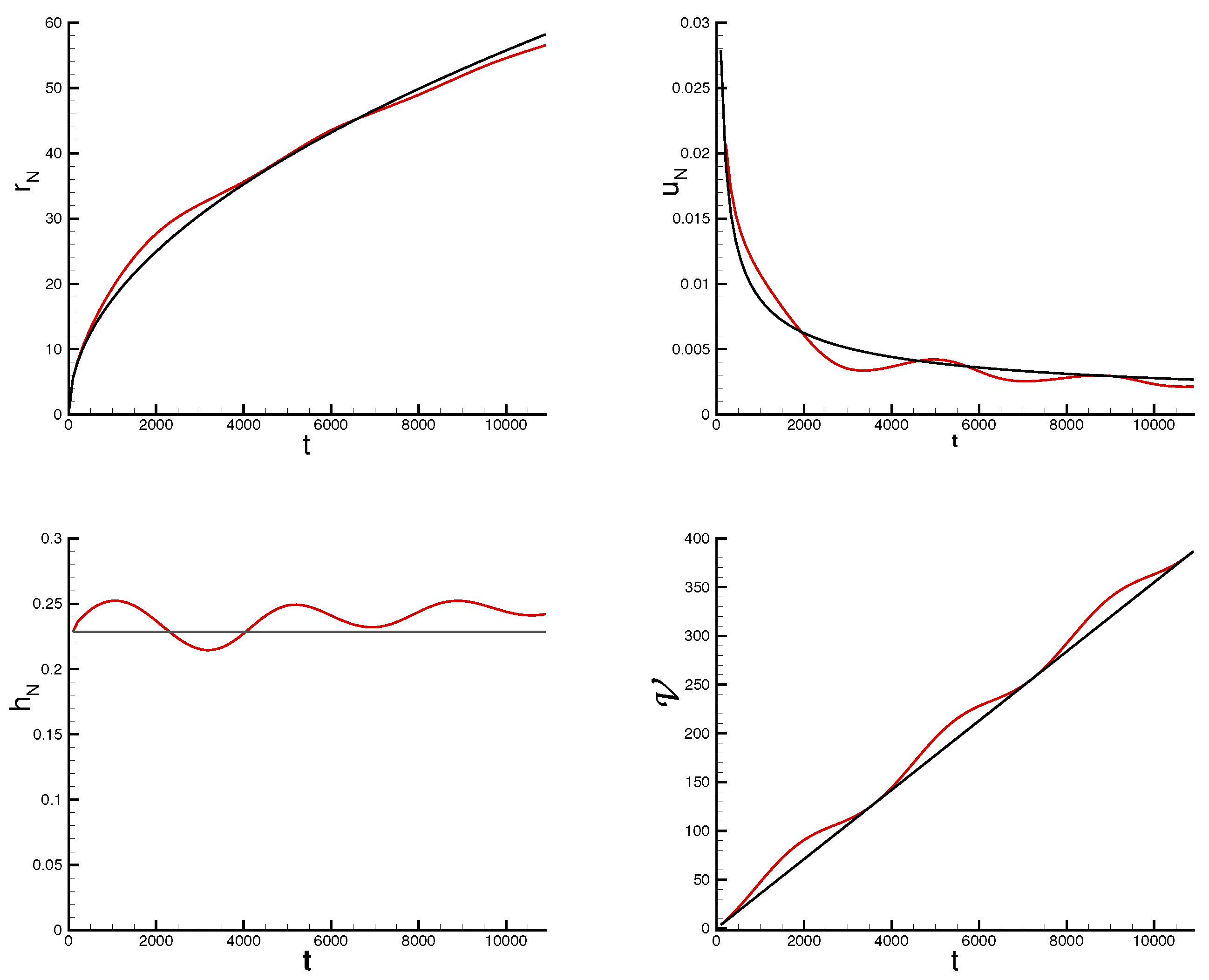
The solution of the improved BM (using γ 2 and I 2 ), in dimensional form, is displayed in Figure 7. We see that the oscillation of the influx is reflected in the behavior of the dependent flow variables, but the difference compared to the constant influx case is small. This could be expected because the volume of the perturbed GC coincides with the unperturbed volume at the end of each period T and because
V ( t ) = 0 t Θ ( t ) d t = q t + 0.25 ( T / π ) [ 1 cos ( 2 π t / T ) ] .

6. Conclusions

We revisited the BM predictions for viscous gravity currents created by an influx over a horizontal boundary. We showed that the basic version (used in previously published studies) contains, in general, two inconsistencies with the physical systems: (a) zero velocity at the source; (b) oversimplified connection between the shear at the bottom and u / h . Moreover, the underlying arguments of this model are somewhat arbitrary, and κ 1 actually contains two adjustable parameters. We presented an improved BM version that corrects these deficiencies while preserving the simplicity and versatility of the model. The prediction κ 2 is unique.
The BM is, in general, an unreliable tool, unless verified by some stringent tests over a wide range of parameters. Here we performed such tests for systems with power-law influx for which rigorous analytical solutions of the reliable lubrication model formulations, as well as laboratory data, are available in the literature. These tests confirm the value of the improved model as a prediction tool.
The interpretation of the results for the α = 0 case requires some care. Since the volume is fixed, the intrinsic origin for t is missing. The similarity solution admits an arbitrary time shift t + const. to a virtual origin. Physically, this reproduces an initial slumping phase during which the flow adjusts to the similarity behavior.
A significant advantage of the BM is the applicability to general (not power law) influx. For such cases, the lubrication-theory formulation is not amenable to analytical reduction (such as similarity behavior), and hence only numerical solutions of the PDEs can be used for predictions. The present analysis is expected to motivate experimental studies of systems with various influx functions (not powers of t) for Newtonian and power-law viscosities and the verification and improvement of the new predictions. The present BM seems amenable to various extensions, such as flow in confined gaps and over inclined walls, surface tension effects, and more general non-Newtonian rheology. These extensions require dedicated investigations concerning formulation and verification, and are left for future work.
The improved BM provides quick qualitative and quantitative answers to a wide range of systems, and is thus recommended as a convenient platform for the analysis of practical flows in nature and industry, with future incorporation of additional effects (such as particle sedimentation, heat exchange, curved bottom).
Funding

This research received no external funding.

Institutional Review Board Statement

Not applicable.

Informed Consent Statement

Not applicable.

Data Availability Statement

The original contributions presented in this study are included in the article. Further inquiries can be directed to the corresponding author.

Acknowledgments

The author thanks H. E. Huppert for useful comments and suggestions during the preparation of this paper.

Conflicts of Interest

The author declares no conflicts of interest.

Appendix A. The Shear Formula

The flow of a realistic GC is as sketched in Figure A1. Assume a 2D flow in the x direction with velocity u ( x , z , t ) , and let z = h ( x , t ) be the height of the interface above the bottom. The pressure in the thin-layer GC is hydrostatic, and hence the intrinsic driving force is given by g ( h / x ) , referred to as the buoyancy. The driving force is balanced by the shear, as expressed by the lubrication–simplification momentum equation
0 = g h x + ν z u z n 1 u z .
This equation is integrated twice with respect to z to obtain u ( x , z , t ) . The constants of integration are determined by the boundary condition: (a) no slip, u = 0 , at the bottom z = 0 ; (b) no shear, ( u / z ) = 0 , at the free interface z = h . We obtain
u ( x , z , t ) = n n + 1 G 1 / n h x 1 / n h ( n + 1 ) / n 1 1 z h ( n + 1 ) / n ,
where, again, G = g / ν . The depth-averaged velocity is
u ¯ = u ¯ ( x , t ) = 1 h 0 h u ( x , z , t ) d z = n 2 n + 1 G 1 / n h x 1 / n h ( n + 1 ) / n .
Figure A1. Sketch of the realistic viscous GC. The interface has a continuous negative slope ( h / x < 0 ) from the source to the nose where h = 0 .
Fluids 10 00207 g0a1
Combining (A2) and (A3), the shear stress at the bottom, μ ( u / z ) at z = 0 , can then be expressed as
τ = τ ( x , t ) = ρ ν 2 n + 1 n n u ¯ h n .
The improved BM adopts the result (A4) as an approximation for the calculation of the total shear force, which balances the total buoyancy on the GC; the local balances are not satisfied because h / x = 0 in Figure 1.
We also note that the results (A1)–(A4) carry over to the axisymmetric system upon changing x to the radial coordinate r.
Note the change of notation: In the main text, u ( x , t ) of the BM is intrinsically the depth-average denoted u ¯ in this appendix. The physical (non-averaged) u ( x , z , t ) of this appendix corresponds to u ^ in the main text.

Appendix B. Scaling and Dimensionless Formulas

The dimensionless variables will be denoted by an upper ∼. Let L be the chosen lengthscale. Guided by (A3), The velocity and time are scaled with
U = n 2 n + 1 G 1 / n L ( n + 1 ) / n , T = L U .
We consider time-power law influx, V = q t α .

Appendix B.1. 2D Geometry

The connection between β and α is given by (12), and Ω is defined by (15).
The flux coefficient is scaled with
Q = L 2 T α = L 2 + α / n n 2 n + 1 α G α / n .
The dimensionless form of (1) is expressed as
x ˜ N ( t ) = K ˜ t ˜ β , u ˜ N = β K ˜ t ˜ β 1 .
Using (A5)–(A6), (12), and (13)–(14), and after some algebra, we find that
K ˜ = q ˜ ( 2 n + 2 ) / ( 2 n + 3 ) n 2 n + 1 n / ( 2 n + 3 ) Ω κ .
The result (A8) is valid for an arbitrary L. We note that further simplification can be obtained when the scaling Q, see (A6), is equal to q; this is achieved by setting
L = n 2 n + 1 α G α / n q n / ( 2 n + α ) .
This L is the natural length scale of the 2D GC. For the case α = 0 , q is the fixed volume and L = q 1 / 2 . When (A9) is used,
K ˜ = n 2 n + 1 n / ( 2 n + 3 ) Ω κ .

Appendix B.2. AXI Geometry

The connection between β and α is given by (34), and Ω is defined by (36). The flux coefficient is scaled with
Q = L 3 T α = L 3 + α / n n 2 n + 1 α G α / n .
The dimensionless form of (24) is expressed as
r ˜ N ( t ) = K ˜ t ˜ β , u ˜ N = β K ˜ t ˜ β 1
Using (A5)–(A6), (34), and (35), and after some algebra, we find that
K ˜ = q ˜ ( 2 n + 2 ) / ( 3 n + 5 ) n 2 n + 1 n / ( 3 n + 5 ) Ω κ .
The result (A13) is valid for an arbitrary L. Further simplification is achieved for Q = q , see (A11), by setting
L = n 2 n + 1 α G α / n q n / ( 3 n + α ) .
This L is the natural length scale of the AXI GC. For the case α = 0 , q is the fixed volume and L = q 1 / 3 . When (A14) is used,
K ˜ = n 2 n + 1 n / ( 3 n + 5 ) Ω κ .

Appendix C. The Calculation of κL

The lubrication model combines the the formula (A3) with the continuity equation h t + ( u ¯ h ) x = 0 (or r h t + ( r u ¯ h ) r = 0 ). This yields a PDE for h ( x , t ) (or h ( x , t ) ) (Refs. [8,10,13]).
We use the dimensionless variables as defined in Appendix B. Let k denote the dimension of the flow, k = 2 for 2D and k = 3 for AXI. ξ is the reduced length of the current.
When V = q t , the model admits a similarity solution of the form
x ˜ N ( t ) ( or r ˜ N ( t ) ) = K ˜ t ˜ β ,
h ˜ ( ξ , t ) = K ˜ ( n + 1 ) / ( n + 2 ) λ ( ξ ) t ˜ α ( k 1 ) β , u ˜ ( ξ , t ) = [ λ n + 1 ( λ ) ] 1 / n K ˜ t ˜ β 1 .
Here λ ( ξ ) is the dimensionless height profile of the GC. (The BM postulates a constant λ .) The governing equations show that β is the same as in the BM approximation. The differential continuity equation is reduced to an ordinary differential equation for λ , expressed as
ξ k 2 λ ( 2 n + 1 ) / n λ 1 / n β ξ k 1 λ + α ( k 1 ) β ξ k 2 λ = 0 .
The boundary conditions at ξ = 1 are λ = 0 and [ λ n + 1 ( λ ) ] 1 / n = β (this reproduces the condition u ¯ ( ξ = 1 , t ) = β K ˜ t β 1 ). These boundary conditions impose the behavior
λ ( ξ ) = ( n + 2 ) β n ( 1 ξ ) 1 / ( n + 2 ) ( ξ 1 ) .
The global volume q ˜ t ˜ α balance provides an equation for K ˜ . Recalling the connection between K ˜ and κ L , we obtain the value of the latter. We define
J = 0 1 λ ( ξ ) d ξ ( n + 2 ) / ( 2 n + 3 ) ( 2 D ) ,
J = ξ 0 1 λ ( ξ ) ξ d ξ ( n + 2 ) / ( 3 n + 5 ) ( AXI ) .
Then we can write
κ L = J n 2 n + 1 n / ( 2 n + 3 ) / Ω ( 2 D ) ,
κ L = J n 2 n + 1 n / ( 3 n + 5 ) / Ω ( AXI ) .
The numerical procedure is as follows. The boundary conditions for λ and λ at 1 Δ for some small Δ (say 0.001) are calculated from (A18). Then (A17) is integrated from this point toward ξ = 0 (we used a Runge–Kutta code). The integrals of (A19) or (A20) are calculated as a by-product, then κ L follows (keeping in mind that Ω depends on the geometry, see (15) and (36)).
We note that (A18) is the leading term in a Frobenius series (powers of ( 1 ξ ) ) solution for λ . This provides the following approximations
0 1 λ ( ξ ) d ξ = A n + 2 n + 3 ( 2 D ) , 0 1 λ ( ξ ) ξ d ξ = A ( n + 2 ) 2 ( n + 3 ) ( 2 n + 5 ) ( AXI ) ,
where A = [ ( n + 2 ) β n ] 1 / ( n + 2 ) . Substitution into (A19)–(A22) gives fairly accurate (two or three digits) estimates of κ L .

References

  1. Ungarish, M. Gravity Currents and Intrusions—Analysis and Prediction; World Scientific: Hackensack, NJ, USA; London, UK; Tokyo, Japan, 2020. [Google Scholar]
  2. Huppert, H.E. Geological fluid mech. In Perspectives in Fluid Dynamics: A Collective Introduction to Current Research; Batchelor, G.K., Moffatt, H.K., Worster, M.G., Eds.; Cambridge University Press: Cambridge, UK, 2000; pp. 447–506. [Google Scholar]
  3. Simpson, J.E. Gravity Currents in the Environment and the Laboratory; Cambridge University Press: Cambridge, UK, 1997. [Google Scholar]
  4. Hoffman, D.A. Understanding the gravity of the situation. Plastics Eng. 2014, 70, 28–31. [Google Scholar] [CrossRef]
  5. Fay, J.A. The Spread of Oil Slicks on a Calm Sea; Hoult, D.P., Ed.; Springer: Boston, MA, USA, 1969; pp. 53–63. [Google Scholar]
  6. Huppert, H.E. The propagation of two-dimensional and axisymmetric viscous gravity currents over a rigid horizontal surface. J. Fluid Mech. 1982, 121, 43–58. [Google Scholar] [CrossRef]
  7. Balmforth, N.J.; Craster, R.V.; Sassi, R. Shallow viscoplastic flow on an inclined plane. J. Fluid Mech. 2002, 470, 1–29. [Google Scholar] [CrossRef]
  8. Di Federico, V.; Malavasi, S.; Cintoli, S. Viscous spreading of Non-Newtonian gravity currents on a plane. Meccanica 2006, 41, 207–217. [Google Scholar] [CrossRef]
  9. Hinton, E.M. Inferring rheology from free-surface observations. J. Fluid Mech. 2022, 937, R4. [Google Scholar] [CrossRef]
  10. Sayag, R.; Worster, M.G. Axisymmetric gravity currents of power-law fluids over a rigid horizontal surface. J. Fluid Mech. 2013, 716, R5. [Google Scholar] [CrossRef]
  11. Chowdhury, M.R.; Testik, F.Y. Laboratory testing of mathematical models for high-concentration fluid mud turbidity currents. Ocean Eng. 2011, 38, 256–270. [Google Scholar] [CrossRef]
  12. Huppert, H.E.; Simpson, J.E. The slumping of gravity currents. J. Fluid Mech. 1980, 99, 785–799. [Google Scholar] [CrossRef]
  13. Longo, S.; Di Federico, V.; Archetti, R.; Chiapponi, L.; Ciriello, V.; Ungarish, M. On the axisymmetric spreading of non-Newtonian power-law gravity currents of time-dependent volume: An experimental and theoretical investigation focused on the inference of rheological parameters. J. Non-Newton. Fluid Mech. 2013, 201, 69–79. [Google Scholar] [CrossRef]
  14. Didden, N.; Maxworthy, T. The viscous spreading of plane and axisymmetric gravity currents. J. Fluid Mech. 1982, 121, 27–42. [Google Scholar] [CrossRef]
  15. Barenblatt, G.I. Scaling, Self-Similarity, and Intermediate Asymptotics; Cambridge University Press: Cambridge, UK, 1996. [Google Scholar]
  16. Longo, S.G. Principles and Applications of Dimensional Analysis and Similarity; Springer: Berlin/Heidelberg, Germany, 2021. [Google Scholar]
  17. Schlichting, H. Boundary Layer Theory, 7th ed.; McGraw-Hill: New York, NY, USA, 1979. [Google Scholar]
  18. Bird, R.B.; Stewart, W.E.; Lightfoot, E.N. Transport Phenomena; John Wiley & Sons, Inc.: New York, NY, USA, 1960. [Google Scholar]
Figure 7. BM AXI results as functions of t for constant influx (black line) and perturbed by oscillation (54). Dimensional, cgs units.
Fluids 10 00207 g007
Table 1. Some comparisons of coefficient κ with data. ϵ is the error (percent) from experimental value.
Type α n κ exp κ L κ 1 κ 2 ϵ L ϵ 1 ϵ 2 Paper
2D10.201.01.111.060.8811.6. 12 . [11]
2D11.00.800.881.150.7810.44. 3 . [14]
AXI10.850.980.981.150.900.17. 8 . [13]
AXI11.00.930.961.150.883.24. 5 . [6]
AXI11.530.900.911.140.821.27. 9 . [13]
AXI20.681.041.011.150.92 3 . 11. 12 . [13]
Disclaimer/Publisher’s Note: The statements, opinions and data contained in all publications are solely those of the individual author(s) and contributor(s) and not of MDPI and/or the editor(s). MDPI and/or the editor(s) disclaim responsibility for any injury to people or property resulting from any ideas, methods, instructions or products referred to in the content.