Article

Steady Radial Diverging Flow of a Particle-Laden Fluid with Particle Migration

Department of Mechanical Engineering, University of Alberta, Edmonton, AB T6G 2G8, Canada
Fluids 2025, 10(8), 200; https://doi.org/10.3390/fluids10080200
Submission received: 30 June 2025 / Revised: 22 July 2025 / Accepted: 30 July 2025 / Published: 1 August 2025
(This article belongs to the Special Issue 10th Anniversary of Fluids—Recent Advances in Fluid Mechanics)

Abstract

The steady plane radial diverging flow of a viscous or inviscid particle-fluid suspension is studied using a novel two-fluid model. For the initial flow field with a uniform particle distribution, our results show that the relative velocity of particles with respect to the fluid depends on their inlet velocity ratio at the entrance, the mass density ratio and the Stokes number of particles, and the particles heavier (or lighter) than the fluid will move faster (or slower) than the fluid when their inlet velocities are equal (then Stokes drag vanishes at the entrance). The relative motion of particles with respect to the fluid leads to particle migration and the non-uniform distribution of particles. An explicit expression is obtained for the steady particle distribution eventually attained due to particle migration. Our results demonstrated and confirmed that, for both light particles (gas bubbles) and heavy particles, depending on the particle-to-fluid mass density ratio, the volume fraction of particles attains its maximum or minimum value near the entrance of the radial flow and after then monotonically decreases or increases with the radial coordinate and converges to an asymptotic value determined by the particle-to-fluid inlet velocity ratio. Explicit solutions given here could help quantify the steady particle distribution in the decelerating radial flow of a particle-fluid suspension.

1. Introduction

Plane radial flow of an incompressible viscous fluid in a diverging channel with two non-parallel straight walls, called “Jeffery-Hamel (JH) flow” [1,2,3,4,5], remains an active research topic with significant practical application [6,7,8,9,10,11,12]. Remarkably, the exact solution of the Navier–Stokes equations in this case admits the so-called “similarity solution” and the problem is reduced to a simpler second-order nonlinear ordinary differential equation with constant coefficients. Recently, the research on JH channel flow has been extended to nanofluids with dispersed nanometer particles. However, to the best of our knowledge, almost all related works on JH channel flow of nanofluids (see, e.g., [13,14,15]) have adopted the single-phase model [16,17,18], which assumes that the dispersed particles and the carrier fluid share the same velocity field and therefore cannot explain many important multiphase flow phenomena such as particle migration. In spite of research on various extended versions of JH-like radial flow in a diverging/converging channel (see, e.g., [19,20,21]), the steady spatial distribution of non-neutrally buoyant particles in radial flow of a viscous or inviscid particle-laden suspension is rarely studied in the literature.
In an attempt to study multiphase particulate radial flow in a diverging channel, it turns out that the governing equations of the multiphase model for particle-laden viscous fluids (with a larger number of equations than the Navier–Stokes equations for a clear fluid without dispersed particles) do not admit a similarity solution of JH type due to the coupling between radial and circumferential coordinates in the equations of multiphase flows. Actually, the non-existence of JH-like similarity solutions in the multiphase flow is not surprising because the similarity solution of JH type is not admitted even in the axisymmetric diverging pipe flow of a clear fluid without particles [22].
Indeed, the JH-like similarity solutions are restrictively limited to the plane radial flow of a single-phase fluid in a diverging channel bounded by two straight walls, and their extension to multiphase radial flow of a particle-laden fluid could be expected only under some additional restrictive conditions. Therefore, the present work will focus on the JH-like plane radial flow of a particle-laden suspension under the restrictive condition when the no-slip wall conditions are not applied (such as the two types of problems shown in Figure 1 below), with specific interest in the steady particle distribution of a particle-laden suspension attained eventually as a result of particle migration.
The general equations of the two-fluid model for the present problem are given in Section 2. In Section 3, the initial particle velocity field of a particle-laden suspension with uniform particle distribution is studied with an emphasis on the velocity shift between the particles and the suspension. The steady particle distribution of plane radial flow due to particle migration is studied in Section 4 with demonstrated results for various values of the Stokes number of particles heavier or lighter than the carrier fluid, and an asymptotic expression is given for the steady particle distribution for the vanishingly small particle Stokes number. Finally, the main results are summarized in Section 5.

2. Equations of the Present Model

Let us consider an incompressible (viscous or inviscid) fluid with an initially uniform distribution of identical rigid spherical particles of radius rS, as an incompressible particle-fluid suspension.

2.1. General Equations of the Model with Particle Migration

With the present model, the hydrodynamics of an incompressible suspension with dispersed solid spheres is governed by the modified form of Navier–Stokes equations (the gravity not involved)
ρ d v m d t = ρ v m t + v m · v m = p + · μ v + v T ,
d i v v = 0 ,
t ρ + d i v ρ v m = 0 .
where x and t are the vectorial spatial coordinate and time, p(x, t) is the pressure field of the particle-fluid suspension, v(x, t) is the velocity field of the suspension (defined as the velocity field of the geometrical center of the representative unit cell), vm(x, t) is the velocity field of the mass center of the representative unit cell defined by ρ v m = δ ρ S v S + ρ f 1 δ v f (see Equation (A3) in Appendix A), the effective density ρ (per unit volume of the suspension) is given by ρ = ρ S δ + ρ f ( 1 δ ) (see Equation (A2) in Appendix A), and ρS and ρf are the densities of the particles and the fluid, respectively. Here, δ is the volume fraction of particles, μ is the effective viscosity of the suspension estimated by Einstein formula μ = μ f 1 + α δ with the viscosity μf of the fluid in the dilute limit, where α is a real constant, and and 2 are the gradient and Laplacian operators. In general, if the particle volume fraction δ changes with the spatial position and time due to particle migration, the effective mass density ρ and the viscosity μ may depend on the spatial position and time.
As explained in Appendix A, Newton’s second and third laws imply that the resultant external force acting on the representative unit cell, given by the terms on right-hand side of (1), equates to the mass of the unit cell multiplied by the acceleration dvm/dt of its mass center (rather than the acceleration field dv/dt of its geometrical center), which leads to the above modified form of Navier–Stokes Equations (1). Clearly, for a homogenous clear fluid (δ = 0), vm(x, t) = v(x, t) and the Equation (1) reduces to the classical form of Navier–Stokes equations.
For a suspension with non-neutrally buoyant particles (ρSρf), we have vm(x, t) ≠ v(x, t). As explained in Appendix A, with gravity not involved, an additional relationship between vm(x, t) and v(x, t) is given as
v m + a d v m d t + C L 2 ρ r S 2 9 μ v m × × v = v + b d v d t + C L 2 ρ r S 2 9 μ v × × v ,
a = 1 + C a ρ ρ S 2 ρ S r S 2 9 μ , b = a ρ f ρ + 1 + C a ρ S ρ f δ C a ρ + ρ S .
Here, d/dt denotes the material derivative of the associated velocity field along its own streamlines, Ca and CL are the added mass and the lift force coefficients (Ca = CL = 0.5 is often adopted in the literature), respectively, the coefficients a and b are derived by considering the Stokes drag, the forces acting on particles due to added mass and fluid acceleration [23,24], and the lift force [25,26,27,28], although the lift force vanishes for the present problem of r-dependent radial flow with × v = 0 . Here, it should be stated that the Stokes drag-based models of particle-laden inviscid fluids have been widely adopted for inviscid particulate flows [29,30,31,32,33].
It is stated that the second terms inside the brackets in the expressions of a and b in Equation (5) will be absent (then a = 2 ρ S r S 2 9 μ ,   b = ρ f ρ a ) if only the Stokes drag is considered, and a = b and vm(x, t) = v(x, t) when either δ = 0 or ρS = ρf (“neutrally buoyant particles”) and then the present model reduces to the single-phase models [16,17,18] (see Equation (A1) in Appendix A).

2.2. Equations for Steady Plane Radial Flow

It can be verified that, unlike a clear viscous fluid (without dispersed particles) that admits the similarity solution of JH-type for radial flow in a diverging channel, the particle-laden viscous suspensions do not admit such a similarity solution for radial flow in a diverging channel. Therefore, in the present paper, we shall focus on the following two problems of steady plane radial flow of an incompressible viscous or inviscid particle-laden fluid shown in Figure 1 whose flow fields depend solely on the radial coordinate r, as follows:
(a)
Axisymmetric plane viscous radial flow from a point source;
(b)
Inviscid radial flow in a diverging channel.
To our knowledge, the radial flow of a particle-laden (viscous or inviscid) suspension shown in Figure 1 has been rarely studied in the literature, although radial flow of a clear fluid (without dispersed particles) from a point source has been the topic of several known works [34,35,36,37]. Clearly, the case (a) is an r-dependent axisymmetric flow, and the inviscid radial flow in a diverging channel shown in the case (b) depends solely on the radial coordinate r because the inviscid flow is free to slip on the straight walls. Since the inviscid flow could often offer an acceptable approximation to the viscous flow with no-slip boundary conditions in the flow region away from the solid walls, the inviscid solutions derived here could be useful for the multiphase viscous radial flow of particle-laden fluids in the flow region away from the solid walls (e.g., along the midline of the diverging channel).
The steady r-dependent radial flow field (u(r), um(r), p(r), δ(r)) in the cylindrical coordinate (r, θ, z) system are given by
v = u ( r ) , 0 ,   0 ,     v m = u m r , 0 ,   0 ,     p r ,     δ r .
Note that
v + v T = 2 u , r 0 0 0 u r 0 0 0 0 ,       · μ ( r ) v + v T = 2 μ ( r ) r 1 r r r u + u , r μ r 0 0 .
where the subscript “, “ denotes the partial derivative with respect to r. Thus, when the particle migration is involved, it is verified that Equations (1)–(4) give the following 4 nonlinear equations for (u, um, p, δ) as the functions of the single variable r
u m u m r = 1 ρ r p r + 2 ρ r u , r μ r ,
r r u = 0 ,
u m ρ r + ρ ( r ) 1 r r u m , r = 0 .
u m + a u m u m r = u + b u u r ,
Let us assume that the particles and fluid have two independent inlet velocities (u0S, u0f) with the constant inlet particle fraction δ0 at the entrance r = r0 shown in Figure 1, thus the inlet values of (um, u) are given by
u r = r 0 = u 0 = δ 0 u 0 S + 1 δ 0 u 0 f ,     u m r = r 0 = u m 0 = ρ S δ 0 u 0 S + ρ f 1 δ 0 u 0 f ρ S ρ f δ 0 + ρ f .
For the conciseness of mathematical analysis, let us confine ourselves to case when the inlet velocity of fluid is not zero (u0f > 0). The results derived could offer a qualitative understanding of the limiting case (u0f = 0) by considering sufficiently small inlet velocity of the fluid.
It follows from Equation (9) that u r = f r , where f is a constant. In the present work, with u r = f r , we shall focus on Equations (10) and (11) for the steady velocity field um(r) and the particle distribution δ(r), and the pressure p(r) can be determined from Equation (8) once um(r) and δ(r) are known.

3. Initial Velocity Field with the Uniform Particle Distribution

In this section, to illustrate why the particulate radial flow with initially uniform particle distribution leads to particle migration, let us first study the initial particle velocity field of a particle-laden viscous suspension with uniformly distributed particles under the assumption that the particle migration is slow enough so that the initial flow field is nearly steady with the constant particle volume fraction and Equation (10) associated with particle migration can be ignored.
Thus, the parameters (δ = δ0, ρ, μ) are all constants in this section, and the unknown radial velocity um(r) is determined by Equation (11), which gives
u m + a u m u m r = f r b 1 r 3 f 2 ,       u r = f r .
For a clear fluid (δ0 = 0) without dispersed particles, it follows from the definition Equation (A3) that vm(x, t) = v(x, t), and we have a = b and
δ 0 = 0 :     u m r = u r = u 0 ( r ) = f 0 r , f 0 = r 0 u 0 f > 0 .
For the particle-laden fluid (δ0 > 0), let us write the particle-disturbed flow field um(r) as
δ 0 > 0 :     u m r = u r + r ,       f = f 0 + r 0 δ 0 u 0 S u 0 f .
Here, let us focus on the dilute limit of particle-laden fluids when the volume fraction of particles is much smaller than the unity. With the Einstein formula μ = μ f 1 + α δ , up to the first powers of δ, the δ–dependent coefficients (μ, ρ, a, b) are expanded as
ρ = ρ f 1 + ρ S ρ f ρ f δ ,   μ μ f = 1 + α δ , a = a 0 1 α C a ρ S ρ f C a ρ f + ρ S δ ,       a 0 = 1 + C a ρ f ρ S 2 ρ S r S 2 9 μ f , b = a 0 1 α C a ρ S ρ f C a ρ f + ρ S + ρ S ρ f 2 ρ f C a ρ f + ρ S δ .
where ( 2 ρ S r S 2 9 μ f ) is the dimensional relaxation time of suspended particles, and a 0 = C a 2 ρ f r S 2 9 μ f is the modified relaxation time for massless gas bubbles due to the added mass. The coefficient α depends on the nature of dispersed particles. Typically, α = 2.5 is commonly adopted for rigid spheres, and α = 1 is suggested for spherical gas bubbles in a liquid [38,39].
For the dilute particle-fluid suspensions with the small number δ << 1, the disturbed velocity field Δ(r) = um(r) − u(r) scales with the number δ, and therefore Δ(r) is of the order δ. Substituting Equations (14) and (15) into Equation (12) and ignoring all nonlinear terms of Δ(r) and δ, the linear equation for Δ(r) gives
r + r 2 a 0 f 0 a 0 f 0 r = δ 0 r 2 f 0 ρ S ρ f 2 ρ f C a ρ f + ρ S ,
with the boundary condition at the entrance
r = r 0 = u m 0 u 0 = ρ S ρ f δ 0 1 δ 0 u 0 S u 0 f ρ S ρ f δ 0 + ρ f .
The homogeneous solution of Equation (17) is of the form r e r 2 2 a 0 f 0 . Here, in the case f0 ≠ 0, using the method of variation in constants for Equation (17), an explicit solution of Δ(r) for Equation (17) is given by
r = ρ S ρ f δ 0 1 δ 0 u 0 S u 0 f ρ S ρ f δ 0 + ρ f r 0 e r 0 2 2 a 0 f 0 + δ 0 f 0 ρ S ρ f 2 ρ f C a ρ f + ρ S r 0 r e t 2 2 a 0 f 0 t 3 d t r e r 2 2 a 0 f 0 .
We are particularly interested in the relative velocity of the particles with respect to the fluid. Based on the general relation Equation (A4), we have
u S u = ρ u m u δ ρ S ρ f ,     u S u f = ρ u m u δ 1 δ ρ S ρ f .
Thus, up to the lowest order of δ, the velocity difference between the particles and the fluid normalized by the volume-averaged velocity of the suspension is given by
u S u f u = ρ u 0 S u 0 f r 0 ρ S ρ f δ 0 + ρ f f e r 0 2 2 a 0 f 0 + ρ ρ S ρ f f 0 ρ f C a ρ f + ρ S f 1 r * e r 0 2 2 a 0 f 0 t 2 t 3 d t r * 2 e r 0 2 2 a 0 f 0 r * 2 ,   r * = r r 0 1 .
It is seen from Equation (21) that the velocity shift between particles and the fluid vanishes for the neutrally buoyant particles (ρS = ρf); this is consistent with the fact that the lift force [25,26,27,28] responsible for migration of the neutrally buoyant particles vanishes for the r-dependent radial flow with × v = 0 .

3.1. Lighter Particles with Higher Inlet Velocity (u0S > u0f)

Let us first discuss the case when the radial flow is driven by the high-speed injection of a lighter particle with (u0S > u0f). This problem is of major interest in the literature on bubble-driven gas–liquid two-phase flow [40,41,42,43,44,45,46]. It should be stated that the physical concepts and mathematical equations formulated in two-fluid models for dispersed solid spherical particles can be largely applied to fluids with dispersed small spherical gas bubbles when the effects of deformation and non-uniform size distribution of gas bubbles can be ignored [47,48,49,50] (see, e.g., Equation (11) in Magnaudet & Eames [47] or Equations (92–95) in Legendre & Zenit [50]). In particular, because the liquid-to-gas density ratio is of the order of 103, following almost all papers on gas–liquid bubbly flow in the literature, the gas bubbles in a liquid are treated here as massless.
For massless bubbles with (ρS << ρf) and Ca = 0.5 [47,48,49,50], it follows from Equation (21) that
u S u f u = u 0 S u 0 f u 0 f e r 0 2 2 a 0 f 0 2 1 r * e r 0 2 2 a 0 f 0 t 2 t 3 d t r * 2 e r 0 2 2 a 0 f 0 r * 2 ,   r * = r r 0 1 .
Here, let us consider two cases when the inlet velocity of bubbles is moderately or much higher than the inlet velocity of the fluid at the entrance of the flow, with u0S = 2u0f and u0S = 10u0f, respectively. The normalized velocity difference ((uSuf)/u) between the massless bubbles and the fluid given by Equation (22) are shown in Figure 2 and Figure 3 for several typical values of the ratio r 0 2 2 a 0 f 0 , which is considered to be inversely proportional to the (modified) Stokes number of bubbles with a 0 = C a 2 ρ f r S 2 9 μ f , where uS, uf, and u are the velocities of the bubbles, the fluid, and the suspension, respectively.
It is seen from Figure 2 that although the bubbles move faster than the fluid within a finite distance from the entrance (r* = r/r0 = 1), the velocity of bubbles becomes lower than the velocity of fluid beyond that distance. This distance is determined by the bubble-to-fluid inlet velocity ratio and the Stokes number of bubbles. For example, it is seen from Figure 2 for u0S = 2u0f that the velocity of bubbles of a moderate Stokes number presented by r 0 2 2 a 0 f 0 = 1 becomes lower than the velocity of fluid beyond a distance slightly above (r* = 2), while the velocity of bubbles of a larger Stokes number presented by r 0 2 2 a 0 f 0 = 0.01 remains faster than the fluid within the distance above (r* = 6).
For the higher bubble-to-fluid inlet velocity ratio u0S = 10u0f, it is seen from Figure 3 that the velocity of bubbles of a moderate Stokes number presented by r 0 2 2 a 0 f 0 = 1 remains faster than the fluid within the distance above (r* = 3), while the velocity of bubbles of a larger Stokes number presented by r 0 2 2 a 0 f 0 = 0.01 remains faster than the fluid within the large distance abound (r* = 33). In particular, it is seen from Figure 3 that the normalized velocity difference given by Equation (22) in the case r 0 2 2 a 0 f 0 = 0.01 can be very high (beyond 100, too high to be shown entirely in Figure 3) because the suspension velocity diminishes quickly while the bubbles of large Stokes number respond to the decelerating flow field much slower than the suspension.
Since most experiments and numerical simulations on high speed bubble-driven decelerating gas–liquid flow are limited to a diverging channel or pipe of limited finite length [41,42,43] with a nearly stationary liquid, our results shown in Figure 2 and Figure 3 suggest that the bubbles of even a moderate Stokes number will move faster than the liquid within a sufficiently long distance when the bubble-to-fluid inlet velocity ratio is very high, consistent with some known experimental observations and numerical simulations [41,42,43] (as summarized in [41] “The bubble velocity is distinctly different from the liquid. An assumption of homogeneity in velocity for the bubble and the liquid would cause significant discrepancy in predicting the bubble motion”).
In addition, it is worth mentioning that when the inlet velocities (and therefore the coefficient f defined in Equation (13)) change their signs simultaneously, the normalized velocity difference given by the right-hand side of Equation (21) remains unchanged. Thus, our results derived here for a diverging channel are qualitatively valid for a converging channel, which implies that the bubbles accelerate faster than the liquid in the accelerating bubbly flow in a converging channel. This prediction is consistent with those reported by Auton et al. [40] on the bubble injection-driven inviscid radial accelerating pipe flow, as reviewed by Magnaudet & Eames [47], that “the bubble accelerates faster than the liquid”.

3.2. Particles and Fluid Have the Same Inlet Velocity

When the particles and the fluid get into the decelerating flow field (du/dr < 0) in a diverging radial flow with the same inlet velocity (u0S = u0f) at the entrance, because the Stokes drag vanishes there, the heavier (lighter) particles of larger (less) inertia will respond to the decelerating flow field slower (faster) than the fluid. Therefore, the particles heavier (lighter) than the fluid will move faster (slower) than the fluid at least within a certain distance from the entrance. In particular, for the massless bubbles (ρS = 0) with Ca = 0.5, it is readily seen from Equation (A7) of Appendix A that d v d t + 0.5 d v d t d v S d t = 0 and therefore the deceleration d v S d t of the bubbles is three times the deceleration d v d t of the fluid at the entrance when the bubbles and the fluid have the same inlet velocity and the Stokes drag vanishes there, which implies that the velocity of bubbles is slower than the velocity of fluid. Similarly, it is readily seen from Equation (A7) of Appendix A that ρ S + 0.5 ρ d v S d t = 1.5 ρ d v d t and the magnitude of deceleration d v S d t of the heavy particles is less than the magnitude of deceleration d v d t of the fluid at the entrance when the particles and the fluid have the same inlet velocity, which implies that the velocity of heavy particles is faster than the velocity of fluid.
Beyond the entrance, the motion of bubbles is determined by the three terms on the right-hand side of Equation (A7) of Appendix A, although the motion of heavy particles (ρS >> ρf) is dominated by the Stokes drag and the other two terms on the right-hand side of Equation (A7) can be ignored. With the condition (u0S = u0f), Equation (19) gives
u 0 f = u 0 S :     r = δ 0 f 0 ρ S ρ f 2 ρ f C a ρ f + ρ S r 0 r e t 2 2 a 0 f 0 t 3 d t r e r 2 2 a 0 f 0 .
It follows from Equation (21) that
u S u f u = ρ ρ S ρ f ρ f 1 δ 0 C a ρ f + ρ S Ω r * ,       Ω r * r * 2 e r 0 2 2 a 0 f 0 r * 2 1 r * e r 0 2 2 a 0 f 0 t 2 t 3 d t ,       r * = r r 0 1 .
With the dimension r0 of the present problem and the inlet velocity f 0 r 0 at the entrance (r = r0), the ratio r 0 2 2 a 0 f 0 is inversely proportional to the Stokes number of particles.
The dimensionless function Ω(r*) defined in Equation (24), which determines the velocity difference between the particles and the fluid, is plotted in Figure 4 for three different values of r 0 2 2 a 0 f 0 = 1, 3, and 10, respectively. It is seen from Figure 4 and Equation (24) that the particles heavier (or lighter) than the fluid will move faster (or slower) than the fluid velocity. In addition, because the ratio r 0 2 2 a 0 f 0 is inversely proportional to the Stokes number of particles, it is seen from Equation (24) that the velocity difference between the particles and the fluid decreases with an increasing value of r 0 2 2 a 0 f 0 (or decreasing Stokes number of particles), which suggests that the particle migration can be slow for nanofluids of nanometer particles although the long-term particle migration of nanofluids can be relevant and cannot be ignored for a sufficiently long period of time.
It should be stated that all results derived in Section 3 are based on the assumed steady initial flow field with constant parameters (δ, ρ, μ), which only serve to explain the particle migration at the initial stage of the radial flow but cannot offer any detailed data on the steady flow attained eventually as a result of particle migration beyond the initial stage of flow.

4. Steady Particle Distribution of Plane Radial Diverging Flow

Since the radial flow of a particulate fluid with initially uniform distribution of particles cannot remain the uniform particle distribution due to particle migration, it is of major interest to study the steady particle distribution attained eventually as a result of long-term particle migration.
Here, to determine the steady volume fraction δ(r) of particles, substituting Equations (15) and (16) into Equations (10) and (11) and ignoring all nonlinear terms of Δ(r) and δ(r), the linear equations for Δ(r) and δ ( r ) give
ρ S ρ f f 0 r d δ d r + ρ f r r Δ , r = 0 ,
d Δ d r + r 2 a 0 f 0 a 0 f 0 r Δ = f 0 ρ S ρ f 2 ρ f C a ρ f + ρ S δ ( r ) 1 r 2 ,
with the boundary conditions
r = r 0 = ρ S ρ f δ 0 1 δ 0 u 0 S u 0 f ρ S ρ f δ 0 + ρ f , δ r = r 0 = δ 0 .
It follows from Equation (25) and the conditions Equation (27) that
ρ S ρ f δ 0 1 δ 0 u 0 S u 0 f ρ S ρ f δ 0 + ρ f r 0 r Δ r = ρ S ρ f f 0 ρ f δ r δ 0 .
Using Equation (28) to eliminate Δ(r) in Equation (26), the following first-order linear equation for δ(r) can be verified
d δ d r + r a 0 f 0 ρ S + 2 C a + 1 ρ f C a ρ f + ρ S r δ r = B δ 0 r a 0 f 0 1 2 a 0 f 0 r 2 ,
with the constant B given by
B = 1 + 1 δ 0 u 0 S u 0 f ρ f ρ S ρ f δ 0 + ρ f u 0 f .
The homogeneous solution of Equation (29) is of the form
δ r r ρ S + 2 C a + 1 ρ f C a ρ f + ρ S e r 2 2 a 0 f 0 .
On using the variation in constant, the explicit solution of the non-homogeneous equation Equation (29) with the boundary condition Equation (27) gives
δ r * δ 0 = e r 0 2 2 a 0 f 0 + B r 0 2 a 0 f 0 1 r * 1 2 a 0 f 0 t 2 r 0 2 t 1 ρ S + 2 C a + 1 ρ f C a ρ f + ρ S e r 0 2 t 2 2 a 0 f 0 d t × r * ρ S + 2 C a + 1 ρ f C a ρ f + ρ S e r 0 2 2 a 0 f 0 r * 2 , r * r r 0 1 .
As expected, it can be verified from Equation (32) that δ(r*)/δ0 ≡ 1 for the neutrally buoyant particles (ρS = ρf).

4.1. Light Particles with Higher Inlet Velocity

Let us first discuss the two cases discussed in Section 3.1 when the inlet velocity of bubbles are higher than the inlet velocity of the fluid. In these cases with Ca = 0.5 for bubbles, up to the lowest order of δ, we have
δ r * δ 0 = e r 0 2 2 a 0 f 0 + B r 0 2 a 0 f 0 1 r * 1 2 a 0 f 0 t 2 r 0 2 t 3 e r 0 2 t 2 2 a 0 f 0 d t r * 4 e r 0 2 2 a 0 f 0 r * 2 ,       r * r r 0 1 ;   B = u 0 S u 0 f u 0 f .
The dimensionless steady volume fraction of bubbles given by Equation (33), with u0S = 2u0f and u0S = 10u0f, are shown in Figure 5 and Figure 6, respectively, for three values of r 0 2 2 a 0 f 0 .
It is seen from Figure 5 and Figure 6 that the volume fraction of bubbles attains its maximum at a location near the entrance of the flow and after then monotonically decreases with increasing radial coordinate and converges to a finite value determined by the inlet velocity ratio of the bubbles and the fluid, consistent with the conservation of bubbles without considering the breakup of bubbles. In addition, the maximum volume fraction and its location approach the inlet volume fraction multiplied by the inlet velocity ratio and the entrance location of the flow, respectively, as the Stokes number of bubbles approaches zero (or equivalently, as r 0 2 2 a 0 f 0 tends to infinity).

4.2. Particles and Fluid Have the Same Inlet Velocity

On the other hand, when the particles and the fluid have the same inlet velocity (u0S = u0f) with Ca = 0.5, we have B = 1 and
δ r * δ 0 = e r 0 2 2 a 0 f 0 + r 0 2 a 0 f 0 1 r * 1 2 a 0 f 0 t 2 r 0 2 t 1 2 ρ S + 2 ρ f ρ f + 2 ρ S e r 0 2 2 a 0 f t 2 d t r * 2 ρ S + 2 ρ f ρ f + 2 ρ S e r 0 2 2 a 0 f r * 2 ,       r * r r 0 1 .
The dimensionless steady volume fraction of particles given by Equation (34) is plotted in Figure 7 for heavy particles ( 2 ρ S + 2 ρ f ρ f + 2 ρ S 1 ) with three values of r 0 2 2 a 0 f 0 = 1, 3, and 10, respectively. It is seen from Figure 7 that the volume fraction of heavy particles attains its minimum at a location nearby the entrance of the flow, and after then, the particle volume fraction monotonically increases with increasing radial coordinate and converges to a finite value. Particularly, the minimum value of the particle volume fraction and its location approach the inlet value δ0 and the entrance location r = r0 as the value of r 0 2 2 a 0 f 0 approaches infinity, or equivalently as the Stokes number of particles approaches zero.
On the other hand, the dimensionless steady volume fraction of particles given by Equation (34) is plotted in Figure 8 for massless bubbles ( 2 ρ S + 2 ρ f ρ f + 2 ρ S 4 ) with three values of r 0 2 2 a 0 f 0 = 1, 3, and 10, respectively. It is seen from Figure 8 that the volume fraction of massless bubbles attains its maximum at a location near the entrance of the flow, and after then, the bubble volume fraction monotonically decreases with increasing radial coordinate and converges to a finite value. Particularly, the maximum value of the particle volume fraction and its location approach the inlet particle volume fraction δ0 and the entrance location r = r0 as the value of r 0 2 2 a 0 f 0 approaches infinity, or equivalently, as the modified Stokes number of bubbles approaches zero.
To our current knowledge, the existence of the location with the minimum (or maximum) volume fraction of heavier (or lighter) particles in the steady particle distribution of a diverging radial flow has not been reported in the literature (in particular, it is beyond the scope of the single-phase models [16,17,18] based on the assumption of uniformly distributed particles), and therefore a comparison of this interesting prediction with known data cannot be made here due to the lack of available related results in the literature. Here, it should also be stated that the motion of neutrally buoyant particles ( ρ S = ρ f ) in a viscous fluid requests a more refined description of various forces acting on dispersed particles that have not been considered by the present relatively simplified two-fluid model, and therefore the present model and derived formulas are not intended to be applied for the particulate radial flow of neutrally buoyant particle-laden fluids.

5. Conclusions

A steady spatial distribution of particles in various flow problems of particle-laden viscous or inviscid fluids is not extensively addressed in the literature. The present work focuses on the diverging plane radial flow of a particle-fluid viscous or inviscid suspension when the velocity field solely depends on the radial coordinate, with particular interest in the steady spatial particle distribution eventually attained as a result of particle migration. Our main results include
(1)
In the initial flow field of a particle-fluid suspension with uniformly distributed particles, the relative velocity of particles with respect to the fluid depends on their inlet velocity ratio, the mass density ratio, and the Stokes number of particles. For example, when their inlet velocities are equal (then Stokes drag vanishes at the entrance), the particles heavier (or lighter) than the fluid will move faster (or slower) than the fluid. On the other hand, the particles lighter than the fluid can remain faster than the fluid within a sufficiently long distance, provided that the inlet velocity of lighter particles is much higher than the inlet velocity of the fluid. This result is qualitatively consistent with some known simulations and experiments on gas–liquid bubbly flow in a diverging channel of finite length driven by high-speed injection of gas bubbles into a nearly stationary liquid;
(2)
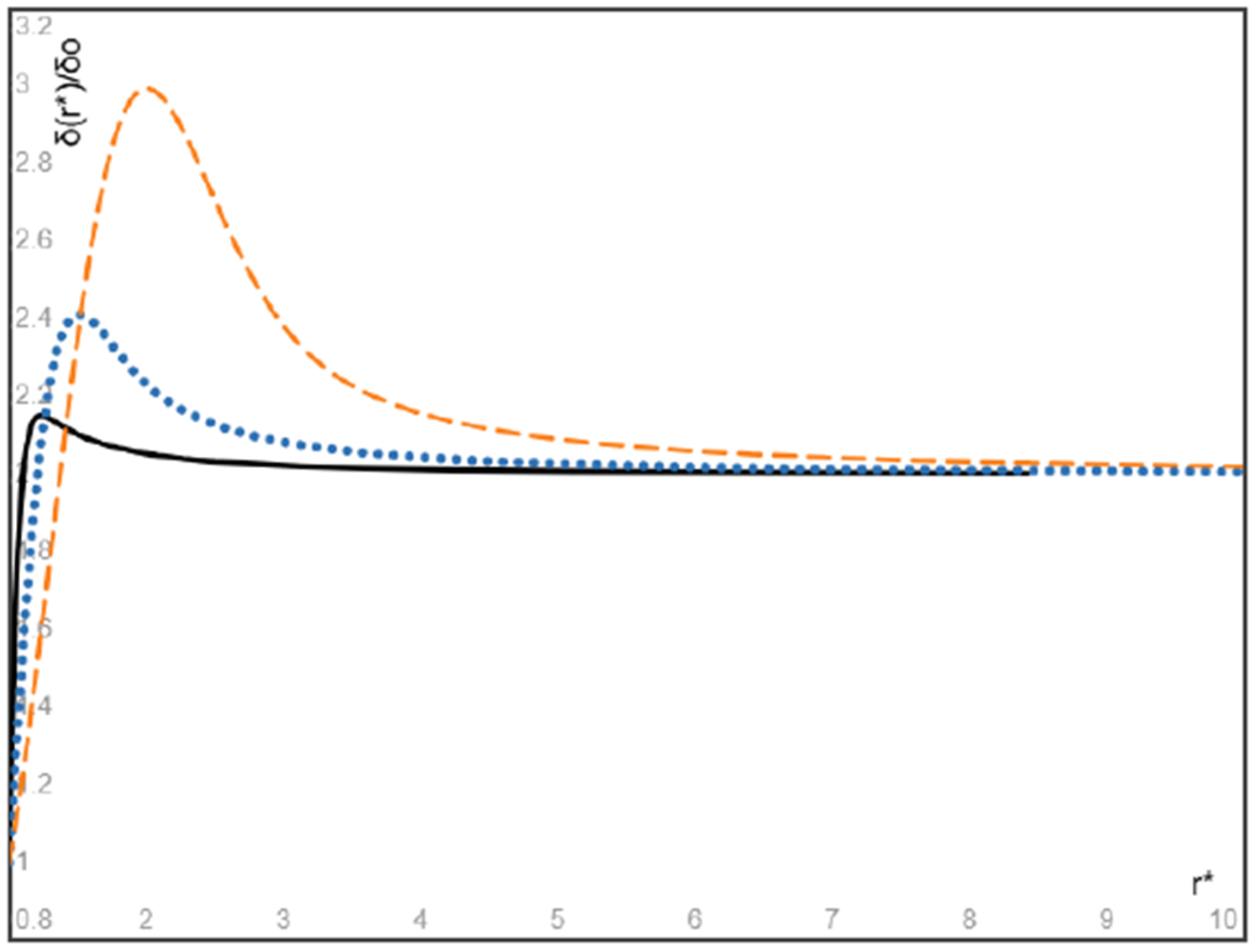
An explicit expression is obtained for the steady spatial distribution of particles eventually attained as a result of particle migration. In particular, for massless gas bubbles with the inlet velocity higher than the inlet velocity of the fluid, our results show that the volume fraction of bubbles attains its maximum at a location close to the entrance of the flow and after then monotonically decreases with increasing radial coordinate and converges to a finite value determined by the inlet velocity ratio of the bubbles and the fluid. As the Stokes number of bubbles approaches zero, the peak volume fraction decreases and converges to the inlet volume fraction of the bubbles multiplied by the inlet velocity ratio, and the location of peak volume fraction approaches the entrance location of the flow;
(3)
When the particles and the fluid have the same inlet velocity, our results show that the steady volume fraction of particles heavier than the fluid attains its minimum at a location close to the entrance of the flow and after then monotonically increases with increasing radial coordinate and converges to a finite value, and as the Stokes number of heavy particles approaches zero, the minimum volume fraction and its location approach the inlet particle volume fraction and the entrance location of the flow, respectively. On the other hand, the steady volume fraction of particles lighter than the fluid attains its maximum at a location close to the entrance of the flow and after then monotonically decreases with increasing radial coordinate and converges to a finite value, and as the Stokes number of lighter particles approaches zero, the maximum volume fraction of light particles and its location approach the inlet particle volume fraction and the entrance location of the flow, respectively.

Funding

No external fund is applied for this work.

Data Availability Statement

The data that support the findings of this study are available within the article.

Acknowledgments

The author is grateful to three anonymous reviewers for their constructive comments, which have helped improve the manuscript.

Conflicts of Interest

The author has no known competing financial interests or personal relationships that could have appeared to influence the work reported in this paper.

Appendix A. Derivation of Equations (A1)–(A5)

For an incompressible viscous fluid with uniformly distributed identical solid spheres, the single-phase models [16,17,18] treat it as a homogeneous incompressible viscous fluid with constant effective viscosity μ and mass density ρ, governed by the classical Navier–Stokes equations (in the absence of body force)
d v d t = ρ v t + v · v = p + μ 2 v , d i v v = 0 ,
where x and t are the vectorial spatial coordinate and time, v(x, t) is the velocity field of the particle-fluid suspension (defined as the velocity field of the geometrical center of the representative unit cell), p(x, t) is pressure field of the suspension, and 2 are gradient and the Laplacian operators, the effective mass density ρ (per unit volume) of the suspension is given by
ρ = ρ S δ + ρ f 1 δ ,
where ρs and ρf are the mass densities of the particles and the fluid, respectively, δ is the volume fraction of the particles, μ is the effective viscosity of the suspension estimated by Einstein formula μ = μ f 1 + α δ with the viscosity μf of the carrier fluid in the dilute limit, where α is a constant.
A two-fluid model addresses the decisive role of the relative shift between the velocity field vS(x, t) of suspended particles and the velocity field vf(x, t) of carrier fluid when the particles are not neutrally buoyant (ρSρf). Actually, Newton’s second and third laws imply that the resultant external force acting on the representative unit cell, given by the terms on right-hand side of Equation (A1), equates to the mass of the unit cell multiplied by the acceleration dvm/dt of its mass center (rather than the acceleration field dv/dt of its geometrical center), and consequently, instead of Equation (A1), dv/dt on the left-hand side of Equation (A1) should be replaced by dvm/dt and the particle-fluid suspension is governed by the modified form of Navier–Stokes Equations (1), where vm(x, t) is the velocity field of the mass center of the representative unit cell defined by the mass-averaged velocity field
ρ x , t v m = δ x , t ρ S v S + ρ f 1 δ x ,   t v f ,
where δ(x, t) can change with the spatial position and time due to particle migration, and therefore the density ρ and the effective viscosity μ of the suspension may vary with the spatial position and time.
To derive a relationship between vm(x, t) and v(x, t), let us start with the suspension’s velocity v(x, t) given by the volume-averaged mixture rule v = δ ( x , t ) v S + v f 1 δ ( x ,   t ) . Thus, Equation (A3) gives the following mass-averaged velocity field relation
ρ x , t v m = δ x , t ρ S ρ f v S + ρ f v .
And the mass-averaged acceleration field relation of (A4) gives
ρ d v m d t = ρ S ρ f δ d v S d t + ρ f d v d t ,
where d/dt denotes the material derivative of the associated velocity field along its own streamlines, and vS(x, t) can be given in terms of v(x, t) and vm(x, t) from (A4).
Considering the Stokes drag, forces due to added mass and particle acceleration and the lift force acting on a suspended sphere (of radius rS) that moves with respect to the particulate fluid of the effective viscosity μ and effective mass density ρ, we have (the gravity not involved) [23,24,25,26,27,28]
6 π r S μ v v S + ρ V S d v d t + C a ρ V S d v d t d v S d t + C L ρ V S v v S × × v ,         V S = 4 π r S 3 3 ,
where Ca and CL are the added mass and the lift force coefficients, respectively. The dynamics of the solid sphere is governed by
ρ S V S d v S d t = 6 π r S μ v v S + ρ V S d v d t + C a ρ V S d v d t d v S d t + C L ρ V S v v S × × v .
Dividing both sides by 6 π r S μ , the above equation is reorganized into
a d v S d t = v v S + a 1 + C a ρ C a ρ + ρ S d v d t + C L 2 ρ r S 2 9 μ v v S × × v .
Multiplying ( δ ρ S ρ f ρ ) by both sides of Equation (A8) on using Equations (A4) and (A5) to eliminate the velocity field vs. and its material derivative dvS/dt in Equation (A8), we have the relation Equation (4) with the coefficients a and b given by Equation (5).
Finally, in the case of particle migration with time-varying non-uniform volume fraction δ(x, t) of particles, the conservation of mass for the carrier fluid and solid particles gives
t δ x , t + d i v δ x ,   t v S = 0 ,
t 1 δ x , t + d i v 1 δ x ,   t v f = 0 ,
respectively. In view of Equation (A3) and the above volume-averaged velocity relation, Equations (A9) and (A10) give Equations (2) and (3) in terms of v(x, t) and vm(x, t). In summary, we have eight Equations (1)–(4) for δ(x, t), two velocity fields v(x, t) and vm(x, t), and the pressure field p(x, t).
The present model based on the Stokes drag alone has been used to study the linear stability of plane parallel flow [51] and Kelvin–Helmholtz instability of the fluid interface [52], and it is shown that the results derived by the present model for heavy particles in a dusty gas are identical to the Saffman’s classical results [29] and the results of Michael [30] derived by the classical Saffman model, respectively. This offers supporting evidence for the efficiency and accuracy of the present model. In addition, for the gas bubble–liquid two-phase suspensions, the physical concepts and mathematical equations formulated in the two-fluid models [23,24,25,26,27,28] for spherical solid particles can be largely applied to bubbly fluids with dispersed spherical gas bubbles [47,48,49,50] (see, e.g., Equation (11) in Magnaudet & Eames [47] or Equations (92)–(95) in Legendre & Zenit [50]).

References

  1. Jeffery, G.B. The two-dimensional steady motion of a viscous fluid. Philos. Mag. 1915, 29, 455–465. [Google Scholar] [CrossRef]
  2. Fraenkel, L.E. Laminar flow in symmetrical channel with slightly curved walls, I. On the Jeffery-Hamel solutions for flow between plane walls. Proc. R. Soc. Lond. Ser. A Math. Phys. Sci. 1962, 267, 119–138. [Google Scholar]
  3. Eagles, P.M. The stability of a family of Jeffery-Hamel solutions for diverging channel flow. J. Fluid Mech. 1966, 24, 191–207. [Google Scholar] [CrossRef]
  4. Fujimura, K. On the linear stability of Jeffery-Hamel flow in a converging channel. J. Phys. Soc. 1982, 51, 2000–2009. [Google Scholar] [CrossRef]
  5. Banks, W.H.H. On perturbations to Jeffery-Hamel flow. J. Fluid Mech. 1988, 186, 559–581. [Google Scholar] [CrossRef]
  6. Akulenko, L.D.; Georgievskii, D.V.; Kumakshev, S.A. Solutions of the Jeffery-Hamel problem regularly extendable in the Reynolds number. Fluid. Dyn. 2004, 39, 12–28. [Google Scholar] [CrossRef]
  7. Putkaradze, V.; Vorobieft, P. Instabilities, bifurcations, and multiple solutions in expanding channel flows. Phys. Rev. Lett. 2006, 7, 144502. [Google Scholar] [CrossRef]
  8. Haines, P.E.; Hewitt, R.E.; Hazel, A.L. The Jeffery-Hamel similarity solution and its relation to flow in a diverging channel. J. Fluid Mech. 2011, 687, 404–430. [Google Scholar] [CrossRef]
  9. Jotkar, M.R.; Govindarajan, R. Non-modal stability of Jeffery-Hamel flow. Phys. Fluids. 2017, 29, 064107. [Google Scholar] [CrossRef]
  10. Noureen; Marwat, D.N.K. Double-diffusive convection in Jeffery-Hamel flow. Sci. Rep. 2022, 12, 9134. [Google Scholar] [CrossRef]
  11. Goli, S.; Saha, S.K.; Agrawal, A. Physics of fluid flow in an hourglass (converging-diverging) microchannel. Phys. Fluids 2022, 34, 052006. [Google Scholar] [CrossRef]
  12. Kumar, A.; Govindarajan, R. On the intense sensitivity to wall convergence of instability in a channel. Phys. Fluids 2024, 36, 104108. [Google Scholar] [CrossRef]
  13. Rezaee, D. Linear temporal stability of Jeffery-Hamel flow of nanofluids. Eur. J. Mech. B/Fluids 2024, 107, 1–16. [Google Scholar] [CrossRef]
  14. Rana, P.; Shukla, N.; Areekara, S.; Pop, I. Multiple solutions and temporal stability for ternary hybrid nanofluid flow between non-parallel plates. J. Appl. Math. Mech. (ZAMM) 2024, 104, e202400124. [Google Scholar] [CrossRef]
  15. AI-Saedi, A.A.; Verma, L.; Meher, R.; Nikan, O. Study on Jeffery-Hamel nano-fluid flow with uncertain volume fraction using semi-analytical approach. AIP Adv. 2025, 15, 045113. [Google Scholar] [CrossRef]
  16. Park, H.M. Comparison of the pseudo-single-phase continuum model and the homogeneous single-phase model of nanofluids. Int. J. Heat Mass Transf. 2018, 120, 106–116. [Google Scholar] [CrossRef]
  17. Saha, G.; Paul, M.C. Investigation of the characteristics of nanofluids flow and heat transfer in a pipe using a single phase model. Int. Commun. Heat Mass Transf. 2018, 93, 48–59. [Google Scholar] [CrossRef]
  18. Turkyilmazoglu, M. Single phase nanofluids in fluid mechanics and their hydrodynamic linear stability analysis. Comput. Methods Programs Biomed. 2020, 187, 105171. [Google Scholar] [CrossRef] [PubMed]
  19. AI-Nimr, M.A.; Hammoudeh, V.A.; Hamdan, M.A. Effect of velocity-slip boundary conditions on Jeffery-Hamel flow solutions. J. Appl. Mech. (ASME) 2010, 77, 041010. [Google Scholar] [CrossRef]
  20. Turkyilmazoglu, M. Extending the traditional Jeffery-Hamel flow to stretchable convergent/divergent channel. Comput. Fluids 2014, 100, 196–203. [Google Scholar] [CrossRef]
  21. Soliman, H.M. Laminar, radial flow of two immiscible fluids in slender wedge-shaped passages. J. Fluids Eng. (ASME) 2017, 139, 081201. [Google Scholar] [CrossRef]
  22. Sahu, K.C.; Govindarajan, R. Stability of flow through a slowly diverging pipe. J. Fluid Mech. 2005, 531, 325–334. [Google Scholar] [CrossRef]
  23. Klinkenberg, J.; de Lange, H.C.; Brandt, L. Linear stability of particle laden flows: The influence of added mass, fluid acceleration and Basset history force. Meccanica 2014, 49, 811–827. [Google Scholar] [CrossRef]
  24. Ru, C.Q. Rotational flow field of a particle-laden fluid on a co-rotating disk. Phys. Fluids 2024, 36, 113356. [Google Scholar] [CrossRef]
  25. Rubinow, S.I.; Keller, J.B. The transverse force on a spinning sphere moving in a viscous fluid. J. Fluid Mech. 1961, 11, 447–459. [Google Scholar] [CrossRef]
  26. Saffman, P.G. The lift on a small sphere in a slow shear flow. J. Fluid Mech. 1965, 22, 385–400. [Google Scholar] [CrossRef]
  27. Boronin, S.A.; Osiptsov, A.N. Stability of a vertical Couette flow in the presence of settling particles. Phys. Fluids. 2020, 32, 024104. [Google Scholar] [CrossRef]
  28. Li, H.; Ku, X.; Lin, J. Eulerian-Lagrangian simulation of inertial migration of particles in circular Couette flow. Phys. Fluids 2020, 32, 073308. [Google Scholar] [CrossRef]
  29. Saffman, P.G. On the stability of laminar flow of a dusty gas. J. Fluid Mech. 1962, 13, 120–128. [Google Scholar] [CrossRef]
  30. Michael, D.H. Kelvin-Helmholtz instability of a dusty gas. Proc. Camb. Philos. Soc. 1965, 61, 569–571. [Google Scholar] [CrossRef]
  31. Yang, Y. The influence of particles on the spatial stability of two-phase mixing layers. Phys. Fluids 1990, 2, 1839–1845. [Google Scholar] [CrossRef]
  32. Dimas, A.A.; Kiger, K.T. Linear instability of a particle-laden mixing layer with dynamic dispersed phase. Phys. Fluids 1998, 10, 253957. [Google Scholar] [CrossRef]
  33. Senatore, G. The effect of non-uniform mass loading on the linear, temporal development of particle-laden shear layers. Phys. Fluids. 2015, 27, 033302. [Google Scholar] [CrossRef]
  34. Goldshtik, M.A.; Shtern, V.N. Loss of symmetry in viscous flow from a linear source. Fluid Dyn. 1989, 24, 151–199. [Google Scholar] [CrossRef]
  35. Shusser, M.; Weihs, D. Stability analysis of source and sink flows. Phys. Fluids 1995, 7, 245–2353. [Google Scholar] [CrossRef]
  36. Putkaradze, V.; Dimon, P. Non-uniform two-dimensional fluid from a point source. Phys. Fluids 2000, 12, 66–70. [Google Scholar] [CrossRef]
  37. Chemetov, N.V.; Starovoitov, V.N. On a motion of a perfect fluid in a domain with sources and sinks. J. Math. Fluid Mech. 2002, 4, 128–144. [Google Scholar] [CrossRef]
  38. Taylor, G.I. The viscosity of a fluid containing small drops of another fluid. Proc. R. Soc. Lond. Ser. A Math. Phys. Sci. 1932, 138, 41–48. [Google Scholar]
  39. Ohie, K. Rheology of dilute bubble suspension in unsteady shear flow. J. Fluid Mech. 2024, 983, A39. [Google Scholar] [CrossRef]
  40. Auton, T.R.; Hunt, J.C.R.; Prud’homme, M. The forces exerted on body in inviscid unsteady non-uniform rotational flow. J. Fluid Mech. 1988, 197, 241–257. [Google Scholar] [CrossRef]
  41. Kuo, J.T.; Wallis, G.B. Flow of bubbles through nozzles. Int. J. Multiph. Flow 1988, 14, 547–564. [Google Scholar] [CrossRef]
  42. Chen, J.; Lei, M.; Lu, S.; Xiao, X.; Yao, M.; Li, Q. Numerical simulation of single bubble motion fragmentation mechanism in Venturi-type bubble generator. Mech. Ind. 2024, 25, 21. [Google Scholar] [CrossRef]
  43. Zhao, L.; Huang, J.; Chen, C.; Gao, J. Investigations on the near-wall bubble dynamic behaviors in a diverging channel. AIP Adv. 2024, 14, 115014. [Google Scholar] [CrossRef]
  44. Zeng, X.; Xu, Y.; Cammi, A.; Fan, G.; Wang, J.; Xiao, Y.; Yan, C. Simulation of the vane-type bubble separator using a hybrid Euler-Euler/volume-of-fluid approach. Phys. Fluids 2025, 37, 043330. [Google Scholar] [CrossRef]
  45. Tribbiani, G. An image-based technique for measuring velocity and shape of air bubbles in two-phase vertical bubbly flows. Fluids 2025, 10, 69. [Google Scholar] [CrossRef]
  46. Nedeltchev, S. Updated review on the available methods for measurement and prediction of the mass reansfer coefficients in bubble columns. Fluids 2025, 10, 29. [Google Scholar] [CrossRef]
  47. Magnaudet, J.; Eames, I. The motion of high-Reynolds-Number bubbles. Annu. Rev. Fluid Mech. 2000, 32, 659–708. [Google Scholar] [CrossRef]
  48. Khan, I. Two-phase bubbly flow simulation using CFD method: A review of models for interfacial forces. Prog. Nucl. Energy 2020, 125, 103360. [Google Scholar] [CrossRef]
  49. Basagni, G. Computational fluid dynamics modeling of two-phase bubble column: A comprehensive review. Fluids 2023, 8, 91. [Google Scholar] [CrossRef]
  50. Legendre, D.; Zenit, R. Gas bubble dynamics. Rev. Mod. Phys. 2025, 97, 025001. [Google Scholar] [CrossRef]
  51. Ru, C.Q. Stability of plane parallel flow revisited for particle-fluid suspensions. J. Appl. Mech. (ASME) 2024, 91, 111005. [Google Scholar] [CrossRef]
  52. Ru, C.Q. On Kelvin-Helmholtz instability of particulate two-fluid flow. Acta Mech. Sin. 2025, 41, 324143. [Google Scholar] [CrossRef]
Figure 1. Plane decelerating radial flow of a particle-laden fluid with the r-dependent velocity field.
Fluids 10 00200 g001
Figure 2. The dimensionless velocity difference ((uSuf)/u) between the massless bubbles and the fluid given by Equation (22) with the inlet velocity ratio u0S = 2u0f, for three larger values of the bubble Stokes number presented by r 0 2 2 a 0 f 0 = 1 (solid black), 0.1 (dotted blue), and 0.01 (dashed orange), respectively, where r * = r r 0 and uS, uf, and u are the velocities of the bubbles, the fluid, and the suspension, respectively.
Fluids 10 00200 g002
Figure 3. The dimensionless velocity difference ((uSuf)/u) between the massless bubbles and the fluid given by Equation (22) with the inlet velocity ratio u0S = 10u0f, for three larger values of the bubble Stokes number presented by r 0 2 2 a 0 f 0 = 1 (solid black), 0.1 (dotted blue), and 0.01 (dashed orange), respectively, where r * = r r 0 .
Fluids 10 00200 g003
Figure 4. The dimensionless function Ω(r*) defined by Equation (24) for the velocity difference ((uS-uf)/u), for the three values of r 0 2 2 a 0 f 0 = 1 (dotted blue), 3 (dashed orange), and 10 (solid black), respectively, where r * = r r 0 .
Fluids 10 00200 g004
Figure 5. The normalized steady bubble volume fraction given by Equation (33) with u0S = 2u0f, for the three values of r 0 2 2 a 0 f 0 = 10 (solid black), 3 (dotted blue), and 1 (dashed orange), respectively, where r * = r r 0 .
Fluids 10 00200 g005
Figure 6. The normalized steady bubble volume fraction given by Equation (33) with u0S = 10u0f, for the three values of r 0 2 2 a 0 f 0 = 10 (dashed orange), 3 (dotted blue), and 1 (solid black), respectively, where r * = r r 0 .
Fluids 10 00200 g006
Figure 7. The normalized steady volume fraction of heavy particles given by Equation (34) with the same inlet velocity of particles and fluid (u0S = u0f), for the three values of r 0 2 2 a 0 f 0 = 10 (solid black), 3 (dotted blue), and 1 (dashed orange), respectively, where r * = r r 0 .
Fluids 10 00200 g007
Figure 8. The normalized steady volume fraction of massless bubbles (ρS << ρf) given by Equation (34) with the same inlet velocity of bubbles and fluid (u0S = u0f), for the three values of r 0 2 2 a 0 f 0 = 10 (solid black), 3 (dotted blue), and 1 (dashed orange), respectively, where r * = r r 0 .
Fluids 10 00200 g008
Disclaimer/Publisher’s Note: The statements, opinions and data contained in all publications are solely those of the individual author(s) and contributor(s) and not of MDPI and/or the editor(s). MDPI and/or the editor(s) disclaim responsibility for any injury to people or property resulting from any ideas, methods, instructions or products referred to in the content.

