Article

Simulation and Optimization of Conveying Parameters for Vertical Screw Conveyor Based on CFD + DEM

1
School of Science, Shanghai Maritime University, Shanghai 201306, China
2
Rizhao Port Technology Innovation Center, Rizhao 276827, China
*
Author to whom correspondence should be addressed.
Fluids 2025, 10(7), 171; https://doi.org/10.3390/fluids10070171
Submission received: 7 May 2025 / Revised: 26 June 2025 / Accepted: 27 June 2025 / Published: 30 June 2025
(This article belongs to the Section Flow of Multi-Phase Fluids and Granular Materials)

Abstract

This study investigates the interaction between airflow and low-density bulk particles within vertical screw conveyors and examines its impact on conveying performance. A combined simulation approach integrating the Discrete Element Method and Computational Fluid Dynamics was employed to model both single-phase particle flow and gas–solid two-phase flow. A periodic model was developed based on the structural characteristics of the conveyor. Particle motion dynamics under both single-phase and coupled two-phase conditions were analyzed using EDEM and coupled Fluent-EDEM simulations. The effects of key operational parameters, including screw speed, filling rate, and helix angle, on mass flow rate were systematically evaluated. A comprehensive performance index was established to quantify conveying efficiency, and its validity was confirmed through analysis of variance on the regression model. Finally, the response surface methodology was applied to optimize parameters and determine the optimal combination of screw speed and filling rate to enhance mass flow efficiency. The results indicate that the gas–solid two-phase flow model provides a more accurate representation of real-world conveying dynamics. Future research may extend the model to accommodate more complex material conditions.

1. Introduction

With the rapid development of bulk carrier conveying systems, vertical screw conveyors have gained prominence in bulk cargo handling systems due to their advantages of dust-free operation, environmental sustainability, high unloading efficiency, and low energy consumption. Widely adopted in port operations, these systems are also increasingly utilized in construction, mining, and agriculture sectors [1].
Without considering the influence of airflow, scholars globally have employed the Discrete Element Method (DEM) to investigate material transport in screw conveyors under non-aerated conditions. For example, Chen et al. [2] analyzed the conveying behavior of viscous materials and optimized parameters such as screw speed, pitch, and clearance using multi-objective models, revealing their effects on efficiency and blade wear. Li et al. [3] explored correlations between operational parameters and performance, applying Response Surface Methodology (RSM) to reduce energy consumption by 15%. Sun et al. [4] simulated non-spherical particle transport and developed a wear model based on shear energy, demonstrating that particle shape significantly affects blade wear. Chen et al. [5] found that power consumption increases with conveyor inclination, with notable backflow zones forming at angles exceeding 20 degrees. Additionally, Sun et al. [6] studied blade axial tilt, showing that increased tilt enhances mass flow rate and particle velocity. Samal [7] focuses on comparing the agglomeration tendency of iron fillers with different coarse and fine particle sizes and two irregular shapes in polymer matrix composites, which provides a theoretical and experimental basis for optimizing the performance of composites.
Traditional single-phase flow analyses focus solely on particle dynamics, neglecting airflow interactions. Studies [8] highlight that higher screw speeds amplify air-particle effects, necessitating airflow consideration in vertical screw conveyor analysis. In practical applications, especially for low-density materials, gas–solid two-phase flow emerges due to varying filling rates.
With the development of computational fluid dynamics (CFD), the integration of CFD with DEM enables comprehensive analysis of air-particle–structure interactions. However, coupled simulations demand significant computational resources. To address this, periodic boundary conditions have been introduced. Meng et al. [9] validated periodic models by showing minimal deviation from full-scale simulations. Chen et al. [10] further refined particle angular velocity predictions by analyzing screw speed effects in periodic models.
Using periodic models, researchers have advanced gas–solid two-phase flow studies. Sun et al. [11] simulated vertical screw conveying via EDEM–FLUENT coupling and proposed a Taylor–Couette–Poiseuille (TCP) vortex-based design, improving productivity by 20%. Wang et al. [12] observed linear axial velocity growth with screw speed up to 60 degrees, beyond which velocity stabilized. Ren et al. [13] mapped axial velocity distributions using a Euler–Euler model, while Sun et al. [14] validated simulation results against experimental data, confirming higher accuracy in two-phase flow models.
Although significant progress has been made in understanding the mechanism of screw conveyors, especially in the use of DEM simulations, the key effects of gas Using periodic models, researchers have advanced gas–solid two-phase flow studies. Sun et al. [11] simulated vertical screw conveying via EDEM Using periodic models, researchers have advanced gas–solid two-phase flow studies. Sun et al. [11] simulated vertical screw conveying via EDEM Using periodic models, researchers have advanced gas–solid two-phase flow studies. Sun et al. [11] simulated vertical screw conveying via EDEM-FLUENT coupling and proposed a Taylor–Couette–Poiseuille (TCP) vortex-based design, improving productivity by 20%. Wang et al. [12] observed linear axial velocity growth with screw speed up to 60 degrees, beyond which velocity stabilized. Ren et al. [13] mapped axial velocity distributions using a Euler–Euler model, while Sun et al. [14] validated simulation results against experimental data, confirming higher accuracy in two-phase flow models.
FLUENT coupling proposed a Taylor–Couette–Poiseuille (TCP) vortex-based design, improving productivity by 20%. Wang et al. [12] observed linear axial velocity growth with screw speed up to 60 degrees, beyond which velocity stabilized. Ren et al. [13] mapped axial velocity distributions using a Euler–Euler model, while Sun et al. [14] validated simulation results against experimental data, confirming higher accuracy in two-phase flow models.
Solid two-phase flow, especially in the vertical configuration of low-density materials, has not been fully addressed in terms of parameter optimization of conveying efficiency. Existing CFD–DEM coupling studies often face computational challenges that hinder comprehensive parameter analysis. Therefore, this research has developed A computationally efficient steady-STATE PRETREATMENT method using FLUENT and EDEM. By comparing single-phase DEM and coupled CFD–DEM simulation, the air–particle interaction mechanism in the two-phase flow is analyzed. The combination of this method and RSM can optimize the conveying parameters to determine the best working setting.

2. Development and Validation of a Minimal Periodic Model

2.1. Simulation Model and Parameter Configuration

Vertical screw conveyors exhibit inherent periodicity in their mechanical structure, with critical operational data predominantly derived from stable conveying zones [15]. To enhance computational efficiency, periodic boundary conditions were implemented in the simulation. The simplified model is illustrated in Figure 1.
Following the modeling approach in [16], the conveyor shaft had an outer diameter of 30 mm, blade outer diameter of 76 mm, pitch of 76 mm, and effective height of 1000 mm, comprising 14 operational pitches. The model was designed to transport low-density bulk materials (e.g., millet), with particles fed through the inlet, elevated by rotating blades, and discharged via a reverse helix structure to ensure smooth outflow. A monitoring surface at the outlet captured discharge data. The experimental stacking angle of Millet is 28.63°, the material parameters of the vertical screw conveyor model are the physical property parameters of mild steel, and the simulation parameters [17] of the experimental objects are shown in Table 1.

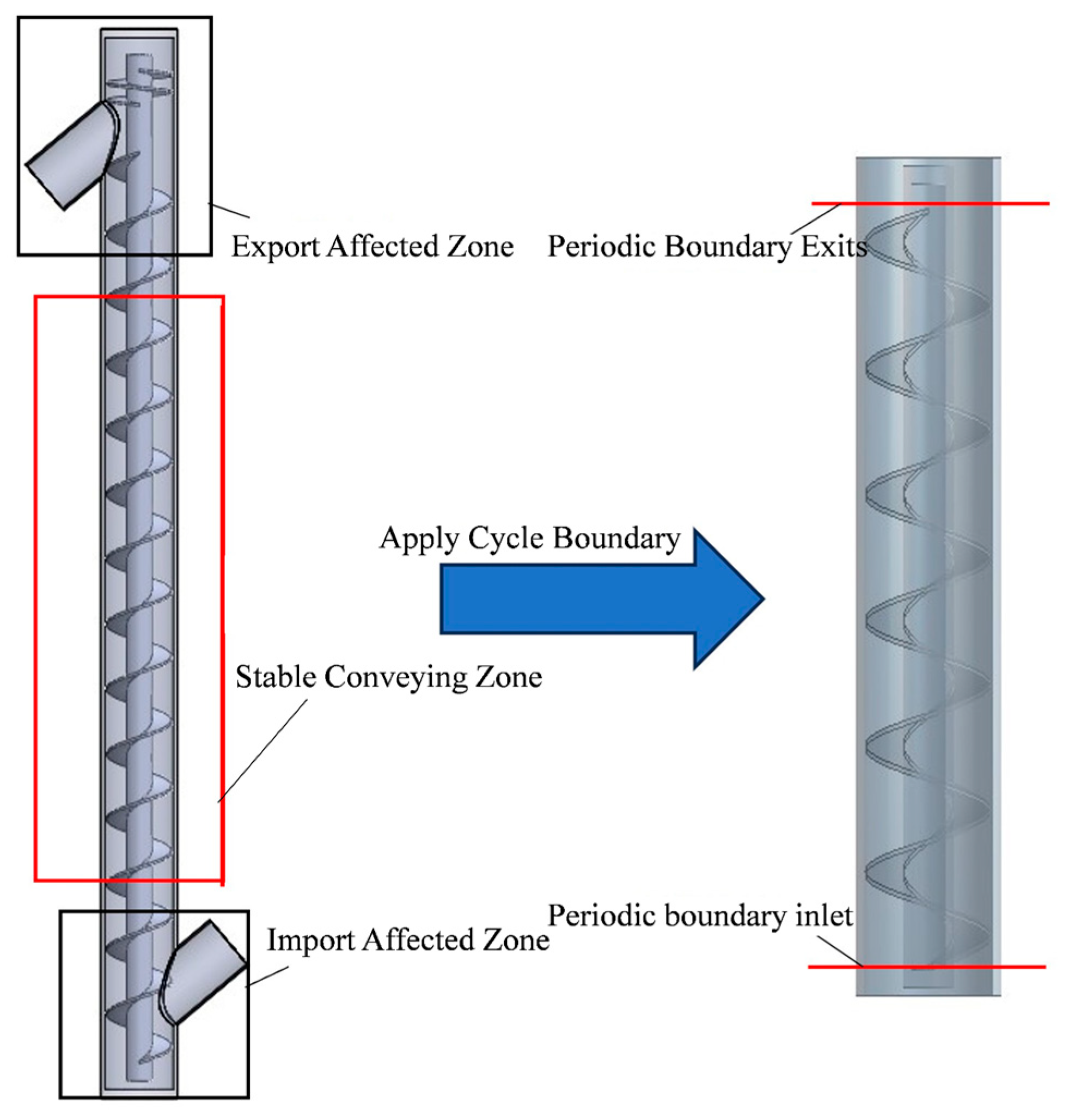
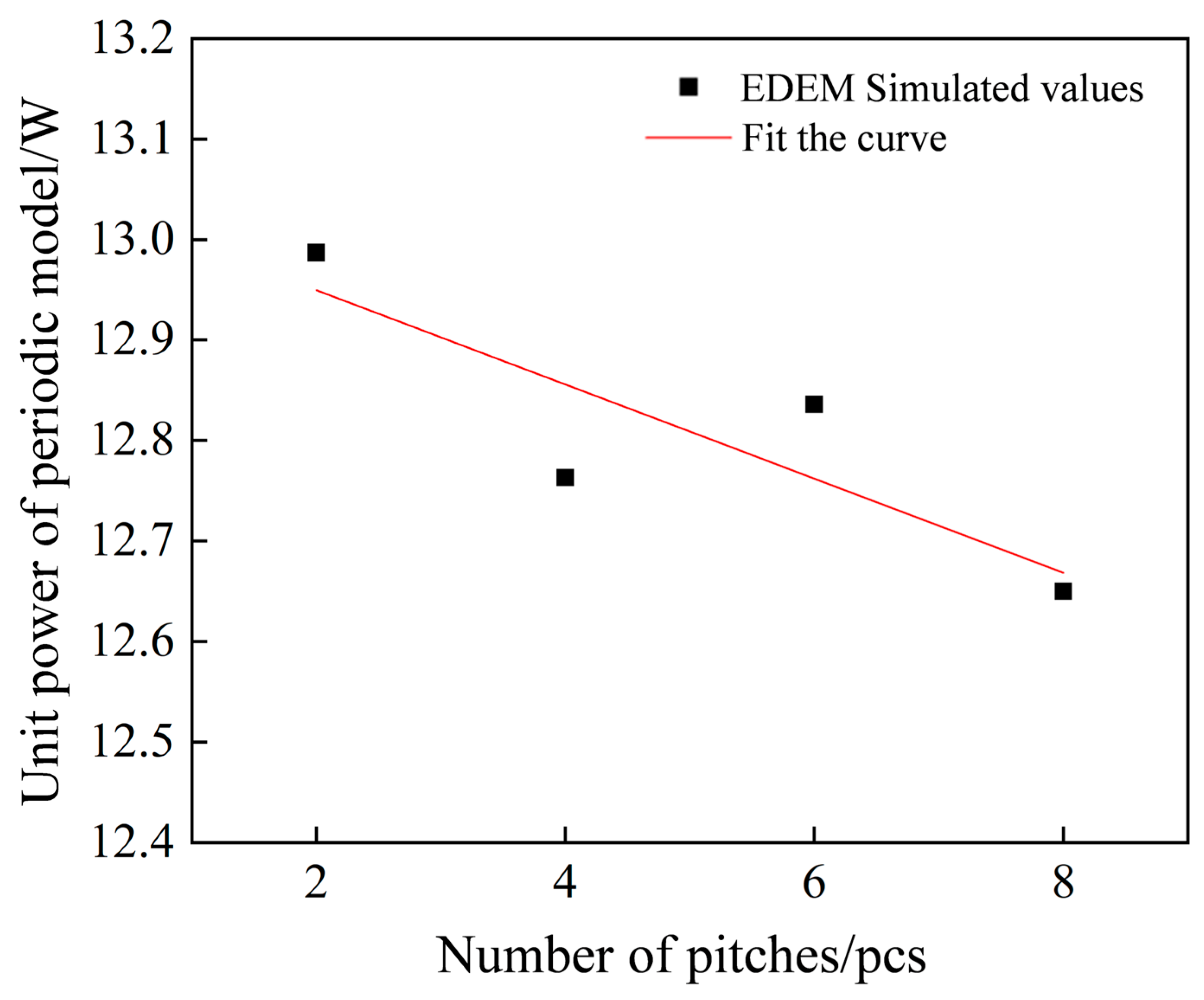
2.2. Determination of the Minimal Periodic Model

In the simplified simulation model of the screw conveyor, the number of particles at different feed levels needed to be determined to calibrate the feed volume due to the removal of the inlet and outlet. For this purpose, the screw speed was fixed at 650 rpm, while feed rates ranged from 0.2 to 0.6 kg/s in 0.1 kg/s increments. EDEM software 2022 monitored particle counts per pitch, with filling rates calculated using Equations (1) and (2):
V 1 = 4 3 π r 3 N
φ = V 1 / V 2
where V1 is total particle volume per pitch, V2 is the volume of cavities per pitch, and the magnitude of this parameter is calculated by the Design Modeler software 2022 as 0.00031 m3, r is particle radius, N is the number of particles in a single pitch of the stable conveying section. φ is the filling rate of the particles.
Figure 2 shows the simulation results between the feed volume and the fill rate in EDEM, with a linear correlation between the two, confirming the material conservation properties of the model.
A full-period model was developed in EDEM software to analyze the effect of screw pitch quantity on particle motion. Monitoring zones were positioned along the axial direction of the screw shaft, as illustrated in Figure 3, and labeled sequentially from A1 to A16 pitches.
Following the configuration of monitoring zones, periodic models with 8, 6, 4, and 2 screw pitches were established and labeled as L8, L6, L4, and L2, respectively. The simulation results (Figure 4) indicate that particle velocity was affected at the inlet and outlet of the periodic boundaries but remained relatively stable in other regions. The mass flow rate in the stable conveying segment showed minimal variation. Therefore, in order to improve the calculation efficiency, it is beneficial to reduce the number of pitches of vertical spiral conveying on the premise of ensuring that the particle movement has a stable conveying area.

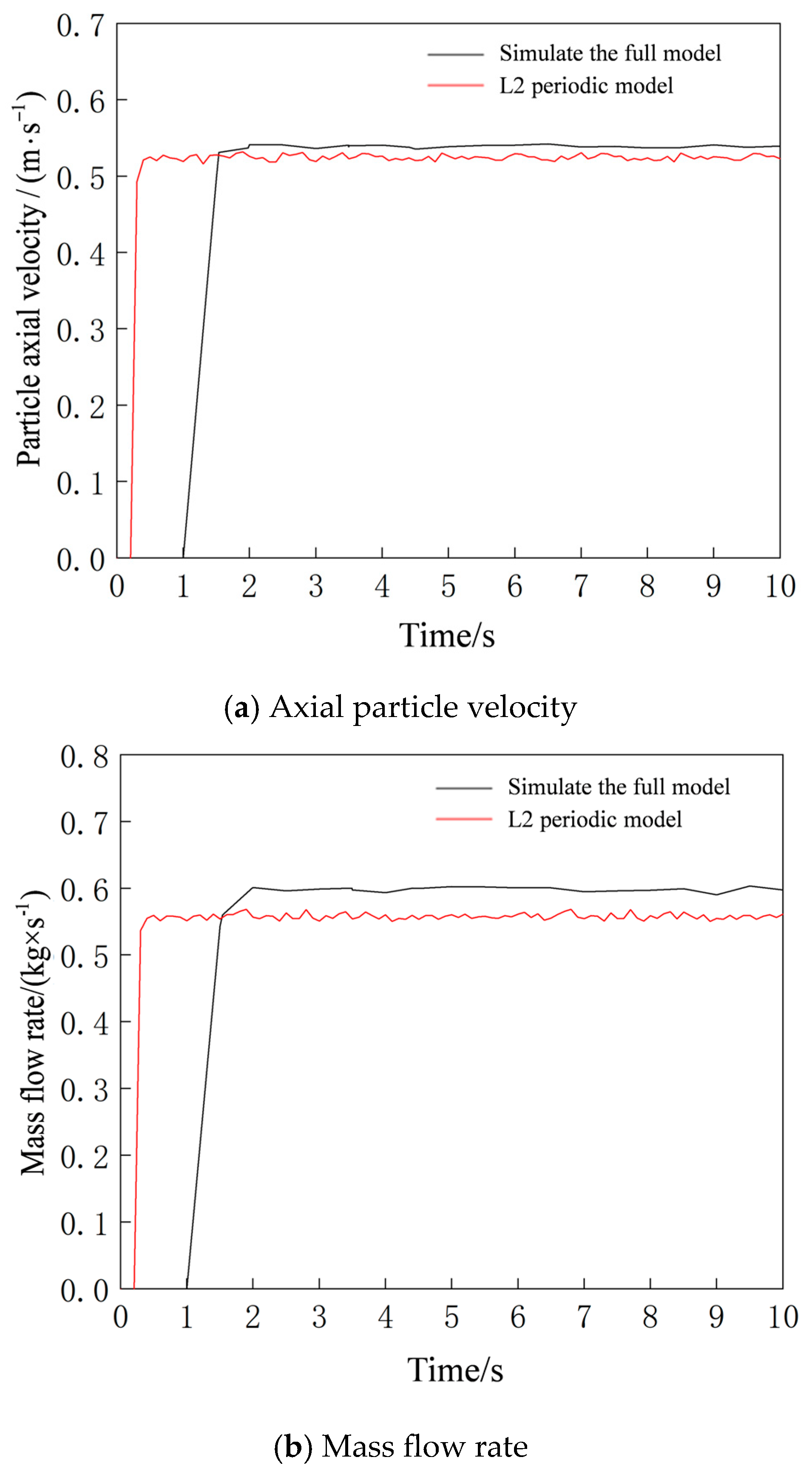
2.3. Comparison of Periodic and Full Models

To validate the periodic boundary model, the average axial particle velocity and mass flow rate were compared between the full model and the periodic model under a screw speed of 650 rpm and a particle fill rate of 0.387 (Figure 5). The periodic model stabilized more rapidly than the full model. After stabilization, the average axial particle velocities in the full and periodic models were 0.538 m/s and 0.526 m/s, respectively, with a relative error of 2.28%. Similarly, the mass flow rates were 0.591 kg/s and 0.558 kg/s, yielding a relative error of 5.91%. These results confirm that the L2 periodic model accurately replicates particle motion within acceptable tolerances.
The full model in EDEM software required 805,566 mesh elements and 440,972 particles, with a computational time of 75 h. In contrast, the periodic boundary model utilized only 45,000 mesh elements and 57,284 particles, reducing the computational time to 12 h, approximately 16% of the full model’s duration. This demonstrates a significant improvement in computational efficiency and cost reduction. Furthermore, the results align with findings in the literature [9], confirming that the L2 periodic model exhibits consistent conveying characteristics when compared to the full model.

3. Simulation Comparison Under Single- and Two-Phase Flow

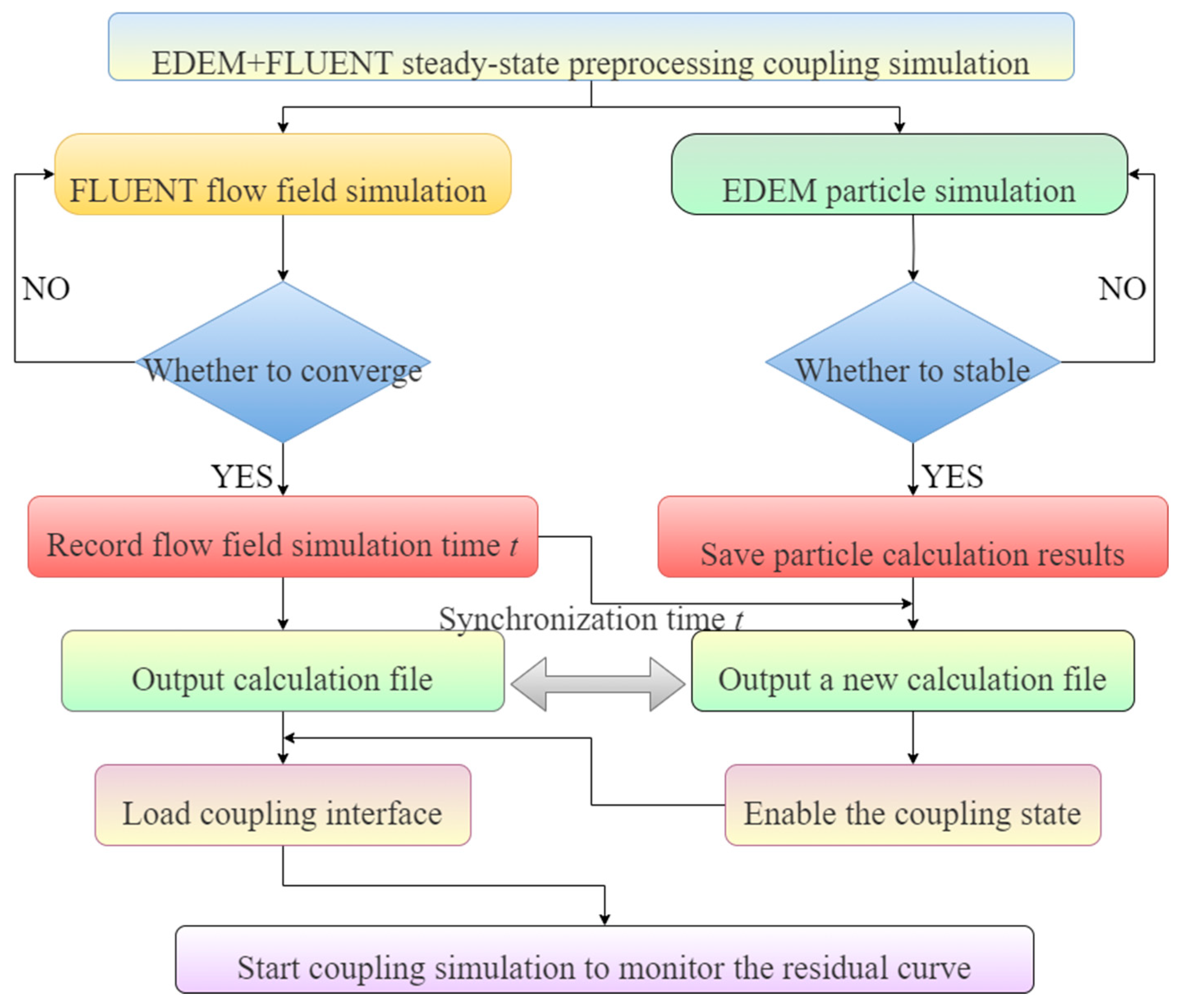
3.1. Steady-State Preprocessing Coupling Method

Directly coupling EDEM particle calculations with FLUENT fluid field simulations leads to slow computational speeds and divergence due to limitations in inter-software time-step synchronization. To address this, the EDEM + FLUENT coupling workflow was optimized as follows:
(1) Independent FLUENT Fluid Field Calculation
Operational parameters were defined in FLUENT to simulate the fluid field independently. Residual curves were monitored until convergence, and the stabilized fluid field data were saved as initial conditions for subsequent coupling.
(2) Independent EDEM Particle Calculation
A periodic boundary model was configured in EDEM to simulate single-phase particle flow until particle motion stabilized. The stabilized particle data were exported, and the initial time was synchronized with FLUENT’s convergence time.
(3) Coupling Interface Loading and Time Synchronization
The coupling function was activated in EDEM, and the coupling interface file was loaded into FLUENT. Time steps were aligned between both software, and initial coupling parameters were verified to ensure consistency between particle and fluid field data.
(4) Coupled Simulation and Residual Monitoring
The EDEM + FLUENT coupled simulation was initiated, with FLUENT residual curves monitored. Results were saved once residuals stabilized or exhibited periodic fluctuations, indicating convergence.
In summary, the steady-state preprocessing methodology for EDEM + FLUENT coupling is illustrated in the workflow diagram in Figure 6.

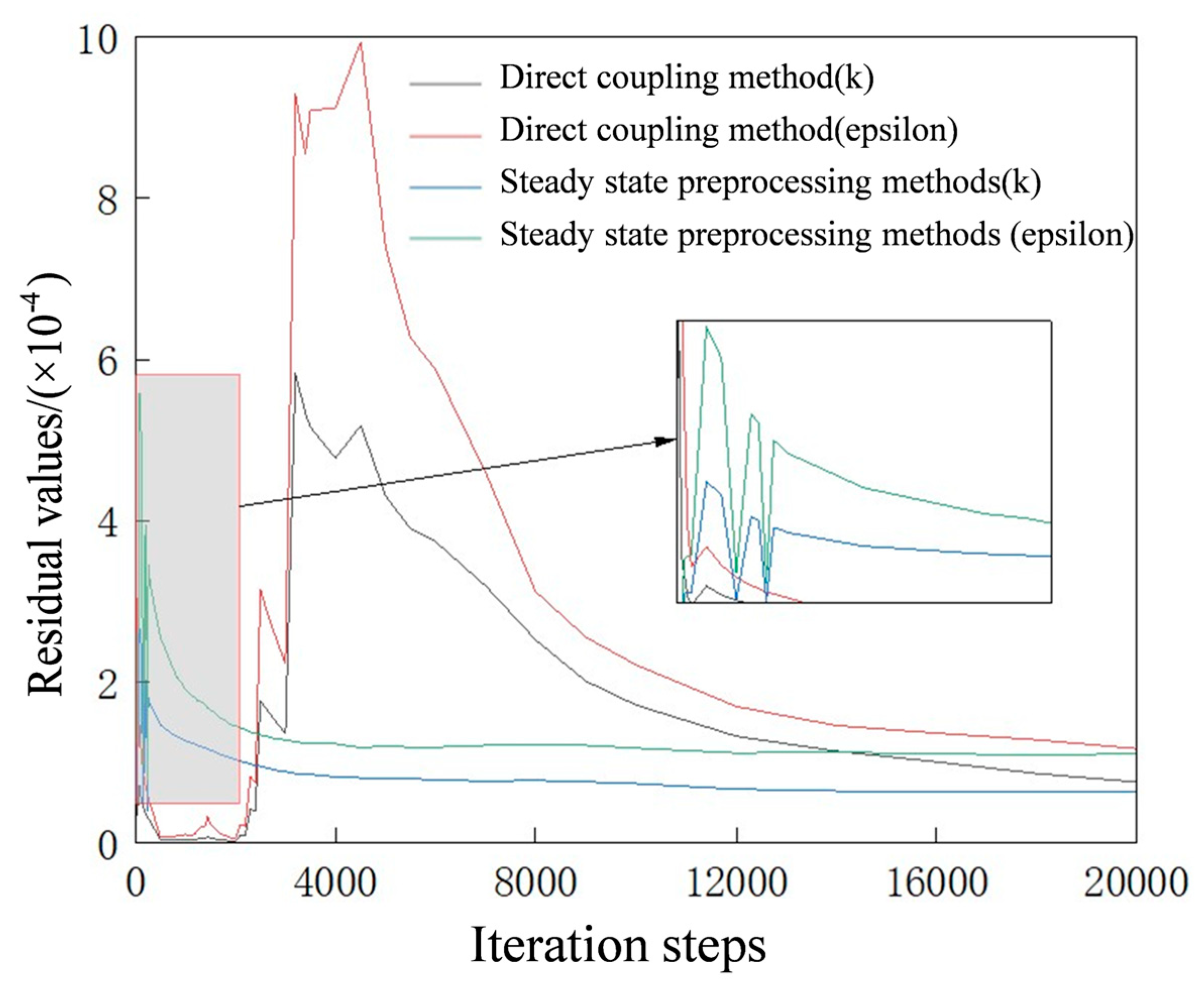
3.2. Comparison of Direct Coupling and Steady-State Preprocessing Methods

To validate the effectiveness of the steady-state preprocessing method, simulations were conducted at a screw speed of 600 rpm and a fill rate of 0.128. The results and residual monitoring data for both strategies are shown in Figure 7 and Figure 8.
The direct coupling and steady-state preprocessing methods produced nearly identical gas–solid two-phase flow simulation results within the vertical screw, confirming the accuracy of the preprocessing approach. Residuals were monitored using the turbulent kinetic energy k and turbulent dissipation rate epsilon from the renormalization group turbulence model. Stabilized residual trends indicate numerical convergence [18]. For the direct coupling method, residuals for k and epsilon initially increased, then decreased before stabilizing. In contrast, the steady-state preprocessing method exhibited significant residual fluctuations during early iterations, followed by a steady decline to stabilization.
The steady-state preprocessing method ensures result accuracy while significantly improving computational efficiency in EDEM + FLUENT coupled simulations. It also avoids divergence caused by abrupt particle introduction into the fluid field.

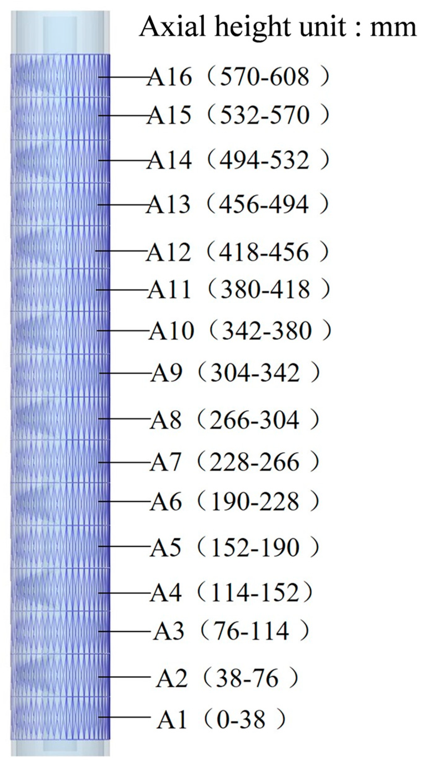
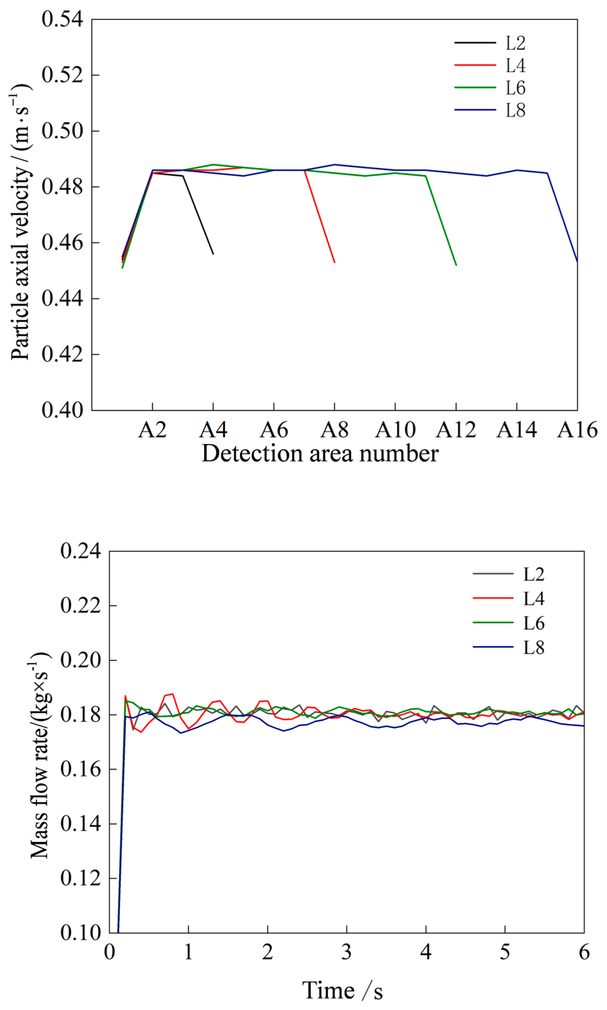
3.3. Comparison of Average Axial Particle Velocity

The mass flow rate, a critical parameter for evaluating vertical screw conveying performance, is calculated using Equation (3):
Q = A ρ ϕ v z ¯
where A is the effective cross-sectional area of the vertical screw, ρ represents the bulk density of the material, and v z ¯ is the average axial particle velocity.
Once the screw and material parameters are fixed, v z ¯ becomes the primary determinant of the mass flow rate.
Analysis of particle motion revealed that axial velocities in vertical screw conveyors exhibit concentrated distributions, with some particles falling or bouncing due to gaps in the screw tube. Gas–solid two-phase flow coupling simulations identified suspended particles whose velocities deviate from the overall conveying behavior, introducing errors. To address this, a probability density-based method was employed to calculate the average axial velocity. This method’s validity was confirmed by comparing results with experimental data from the literature [19]. For example, in an EDEM simulation at 600 rpm and a fill rate of 0.387, axial velocities predominantly ranged from 0.3 to 0.7 m/s. The top five velocity values, ranked by their probability density, were selected for calculation.
As can be seen from Figure 9, the average axial velocity of particles simulated by EDEM + FLUENT is more consistent with the experimental data in Ref. [16] under different spiral speeds and filling rates. Figure 9a demonstrates that simulations neglecting airflow exhibit larger deviations from experimental results, whereas gas–solid two-phase coupling simulations show smaller errors, confirming that the two-phase flow model better reflects real-world conveying dynamics.

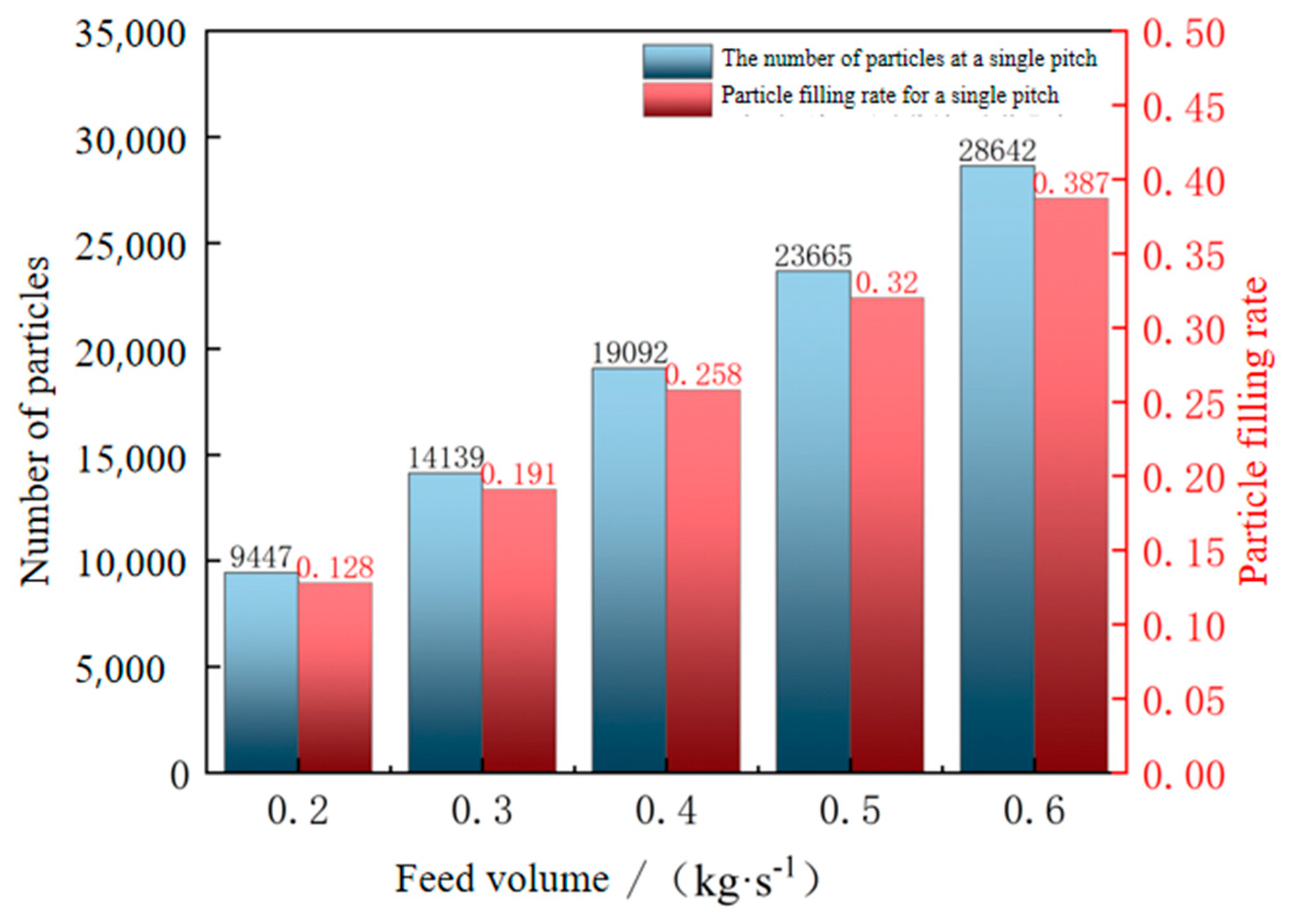
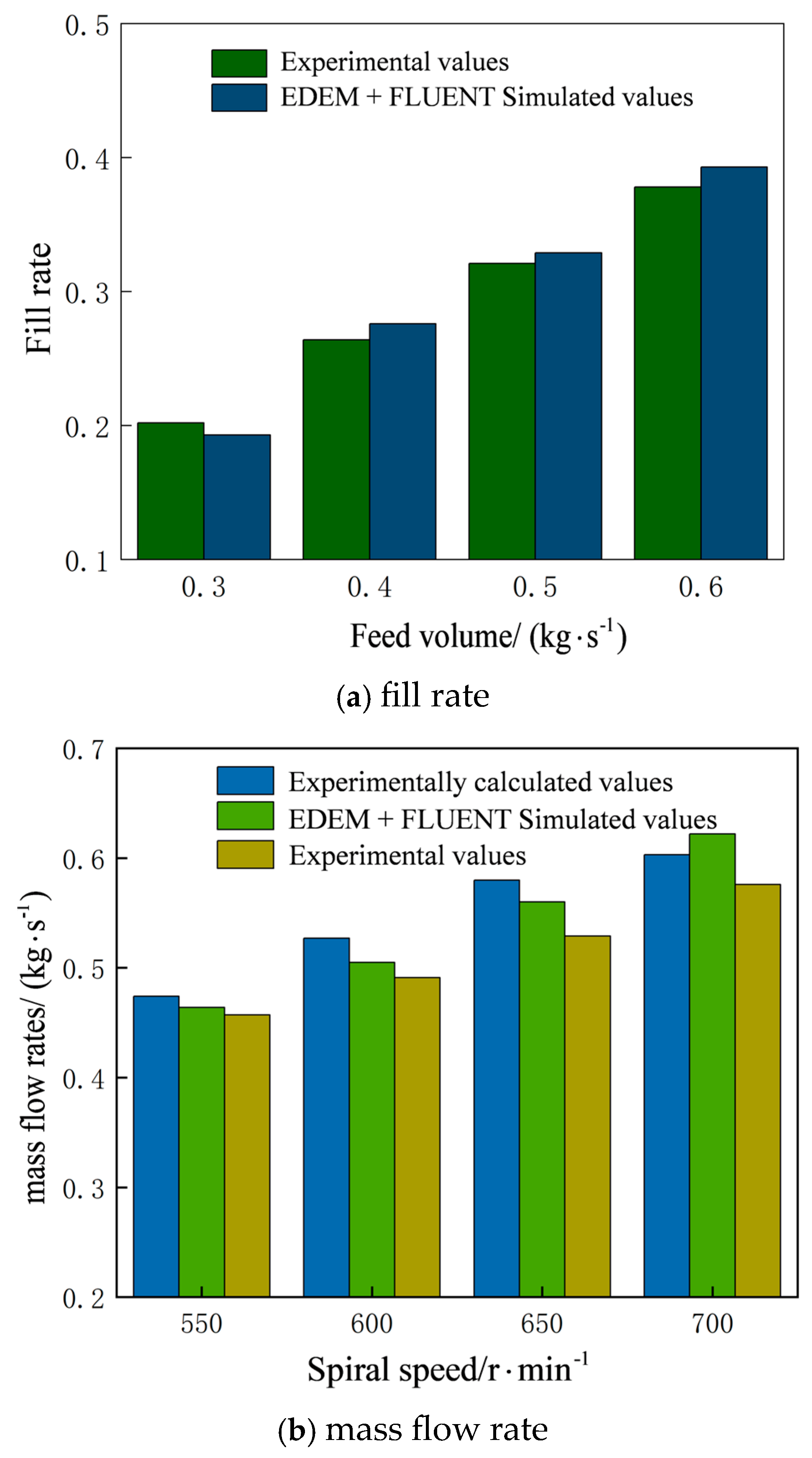
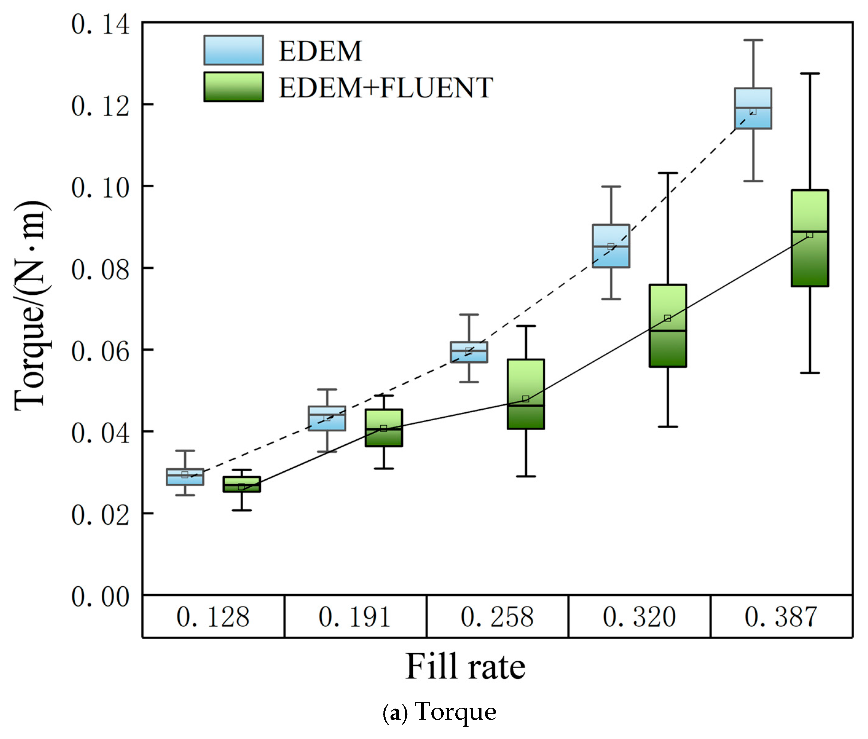
3.4. Comparison of Mass Flow Rate and Fill Rate

The experimental data and EDEM + FLUENT- simulated average axial particle velocities were substituted into Equation (3) to calculate mass flow rates. The relationship between mass flow rate and screw speed was analyzed under three conditions, and simulated fill rates were compared with experimental data based on feed volume variations, as detailed in Figure 10.
As shown in Figure 10a, at a screw speed of 650 r/min, the discrepancy between the simulated and experimental results progressively increased with higher feed rates. However, the simulated particle filling rate closely aligned with experimental values, indicating that the simulation accurately captured the actual material motion. In Figure 10a, it can be seen that the experimental calculation of different spiral speeds [16] and the mass flow rate simulated by EDEM + FLUENT are both greater than the experimental data. The error amplified with increasing screw speeds, suggesting that the mass flow rate and average axial particle velocity are not strictly linear. Beyond a critical threshold, the internal flow regime transitions to turbulence, reducing conveying efficiency. Thus, the system’s performance depends not only on particle velocity but also critically on the gas–solid flow regime.

4. Impact of Two-Phase Flow on Screw Conveyor Performance

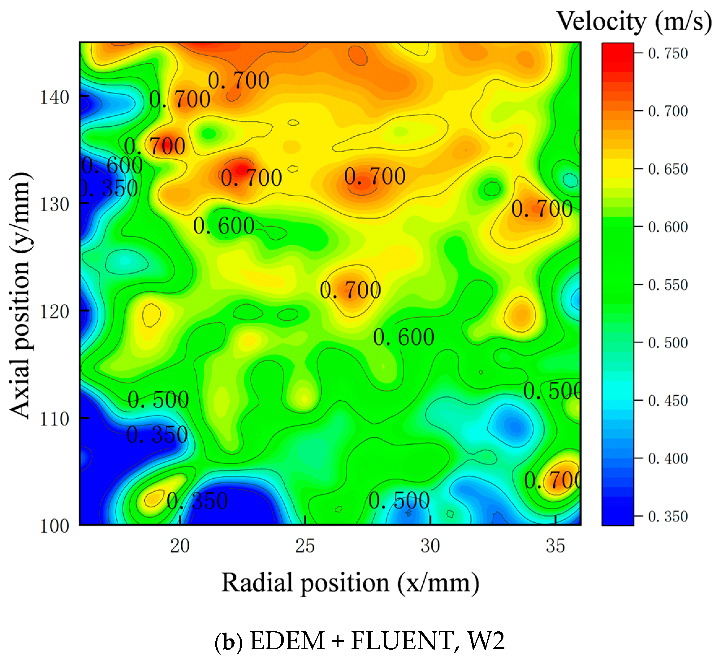
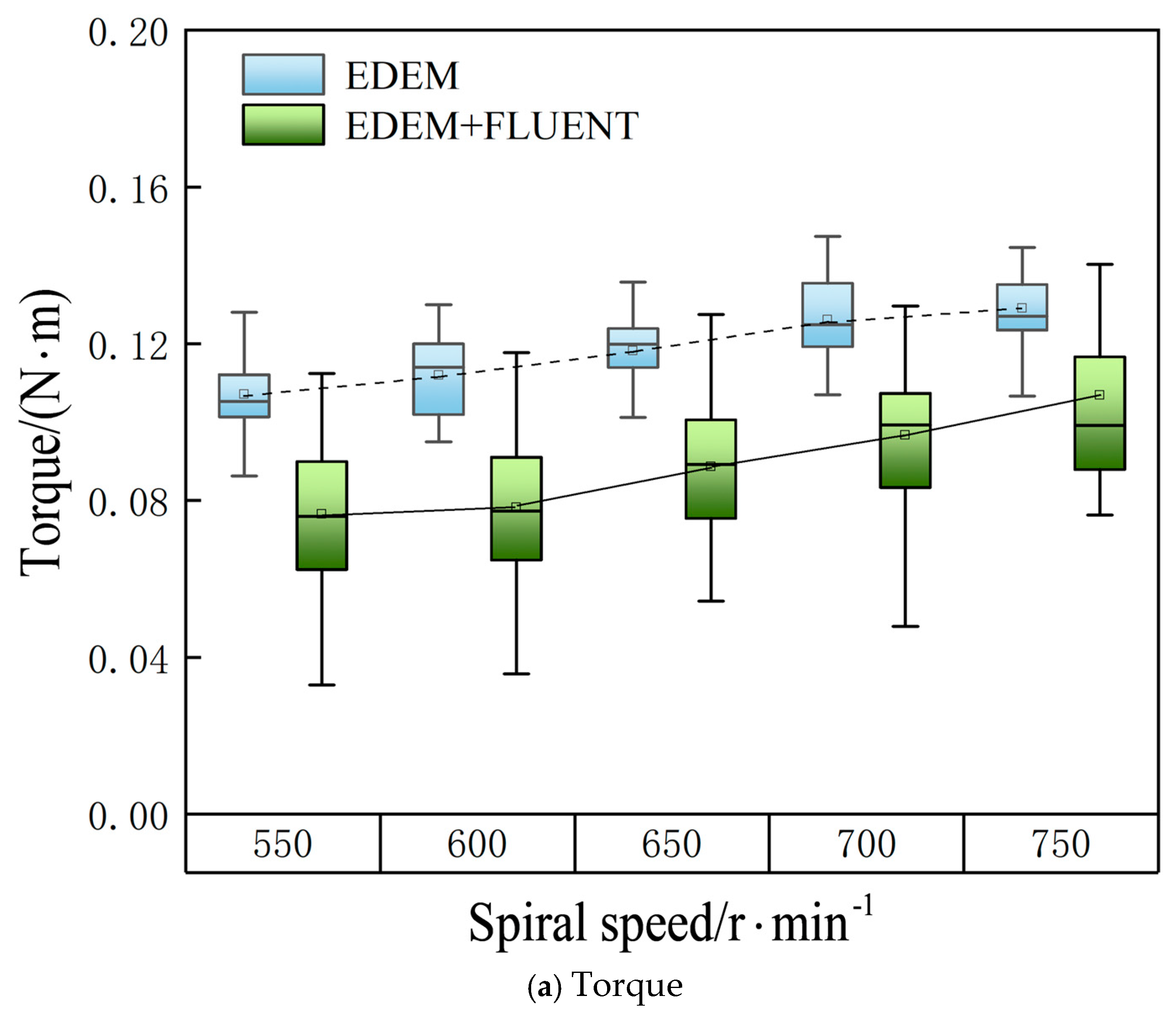
4.1. Effects of Airflow on Particle Motion at Varying Screw Speeds

To analyze the influence of airflow on particle motion in the vertical screw conveyor, experimental conditions were systematically varied, as shown in Table 2:
In a vertical screw conveying system, simulations using EDEM and EDEM + Fluent were conducted under test conditions W1, W2, and W3, where the fill rate remained constant while the screw’s speed varied. As shown in Figure 11, increasing the screw speed elevated the axial velocity of particles in both simulations, though the EDEM + Fluent model exhibited a more pronounced acceleration. Moreover, on the basis of the constant filling rate, the interaction between the airflow and the particles is enhanced with the increase of the spiral speed, and the interaction between the top layer of the particle accumulation and the airflow is more significant, and the height of the particle accumulation also increases.
These findings suggest that, while higher screw speeds enhance upward particle transport in gas–solid flows, excessively high speeds amplify interactions between airflow and top-layer particles. Such conditions may destabilize particle trajectories, increase interparticle collisions, and promote turbulent behavior in the gas–solid flow.
Then, in order to further study the influence of airflow on particle motion, taking the W2 case as an example, with the EDEM simulation and EDEM + FLUENT simulation, as shown in Figure 12, it is found that the axial velocity of particles in the EDEM + FLUENT simulation considering the influence of airflow is significantly improved. Velocity remained stable within the blade–shaft junction (radial position < 25 mm, axial position < 110 mm), while notable acceleration occurred in other regions, especially in the upper particle accumulation layer (axial position >130 mm).
This indicates that there is a particle stagnation zone at the junction of the spiral blades and the spiral shaft, and the axial velocity of the particles in this region is low, and the airflow has an effect on the axial velocity of the particles at different positions, especially the top layer of the accumulated particles that interact strongly with the airflow.
When the spiral speed is kept constant and only the filling rate is changed, P1, 2, and 3 are selected for the test condition, and the two simulation results are shown in Figure 13. Increasing the filling rate elevated particle axial velocity, though the increment remained modest. The EDEM + FLUENT coupled simulation demonstrated a more pronounced velocity increase. As particle stacking height rose, the reduced airflow space intensified flow velocity, significantly accelerating top-layer particles, some of which entered a suspended state. While higher filling rates enhanced overall particle motion, the velocity increase was limited and accompanied by compressed airflow and particle movement space. Furthermore, reduced airflow space at elevated filling rates promoted turbulence generation, altering gas–solid two-phase flow patterns.
As shown in Figure 14, a detailed analysis of axial velocity distributions in the P3 condition reveals a low-speed stagnation zone at the intersection of the spiral blade and shaft, located in the radial position below 25 mm and the axial position below 110 mm. In contrast, the axial velocity increases markedly in the top particle accumulation layer at axial positions exceeding 120 mm, while minimal velocity variations occur in other regions. This demonstrates that airflow has limited influence on particle motion near the blade–shaft intersection but exerts a stronger effect on the top accumulation layer, particularly when the filling rate changes under constant screw speed.

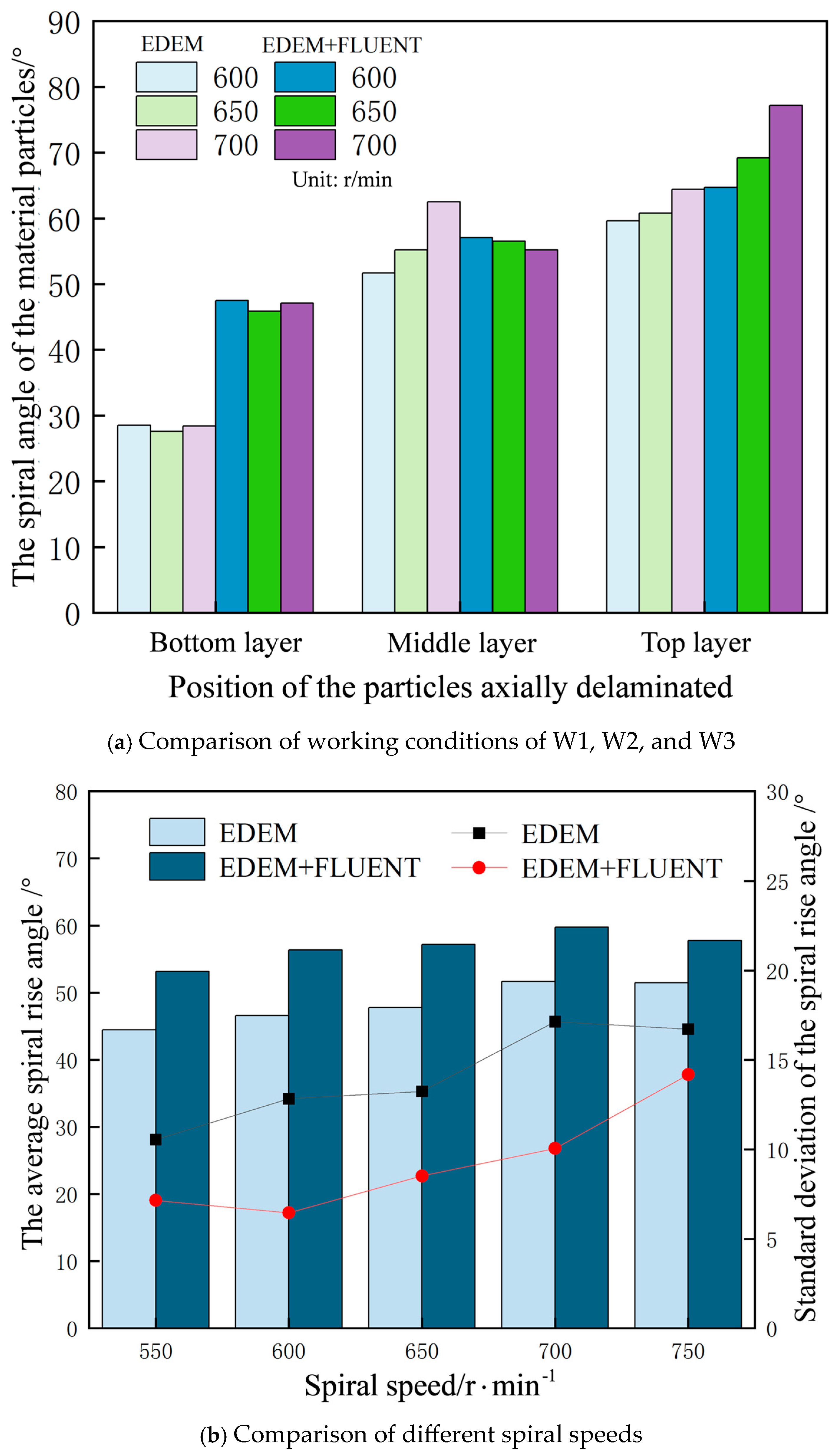
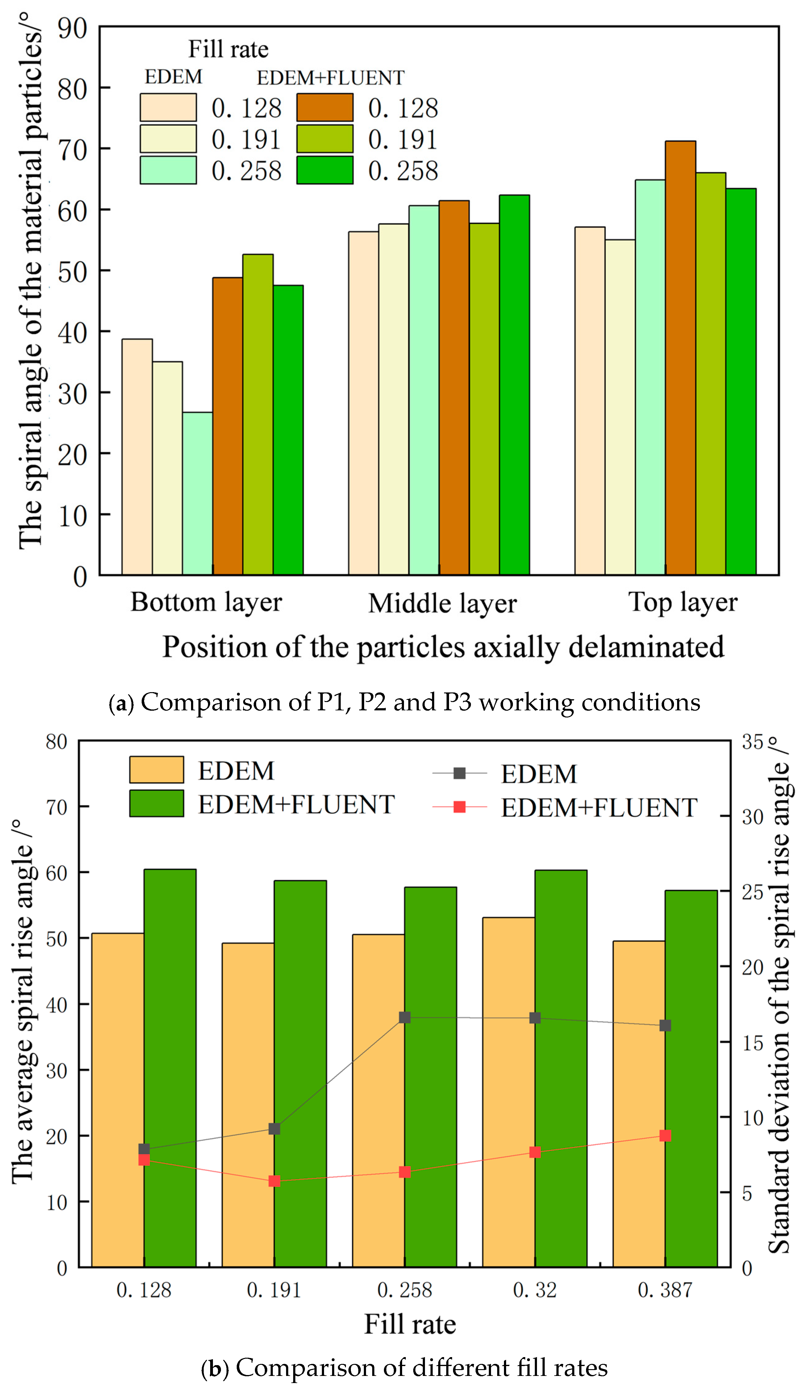
4.2. Impact of Gas–Solid Two-Phase Flow Patterns on Material Lift Angle

Analysis of particle velocities revealed distinct stratification across different regions, with movement stability varying according to screw speed and filling rate, a phenomenon intrinsically linked to gas–solid two-phase flow dynamics. To quantitatively characterize flow states, the helical lift angle of particle flow was introduced. Within the screw airflow field containing particles, the gas–solid two-phase flow predominantly exhibits two patterns: gas–solid two-phase spiral flow and turbulent flow [20]. The gas–solid two-phase spiral flow pattern features parallel flow layers that facilitate upward particle transport, whereas turbulent flow induces interlayer interference that substantially reduces transport efficiency.
Under the working conditions of W1,particle motion vector diagrams from EDEM simulation and EDEM + FLUENT coupled simulation were compared. As shown in Figure 15a, airflow exclusion resulted in marked velocity vector gradients along the screw axis, where bottom-layer particles exhibited reduced transport speed due to upper-layer accumulation constraints.
As particle accumulation height increases, the angle between velocity vectors and spiral blades gradually enlarges, though this angular variation stabilizes in the central accumulation region. As shown in Figure 15b, the motion vector diagram incorporating airflow effects demonstrates that airflow not only influences top-layer particles but also significantly alters the velocity vector orientation of bottom-layer particles. Most particle velocity vectors align parallel, forming a stable gas–solid two-phase helical flow that enhances transport efficiency. Building on velocity vector analysis, the particle bed was stratified into top, middle, and bottom layers along the axial direction to quantitatively investigate helical lift angle variations in gas–solid two-phase flow. Helical lift angles under different screw speeds were calculated through velocity streamline trajectory analysis, with detailed results presented in Figure 15c,d.
Figure 16 illustrates the axial height distribution of helical lift angles under different screw speeds for both simulation methods. In EDEM simulations neglecting airflow, the helical lift angle of bottom-layer particles remains below 30°, while middle and top layers exhibit larger angles. Increasing screw speed elevates both the average helical lift angle and its standard deviation, though beyond 650 r/min the angle growth rate diminishes while deviation continues rising. The EDEM + FLUENT coupled simulation incorporating gas–solid two-phase flow reveals substantial increases in bottom-layer lift angles with speed escalation, with top-layer angles surging abruptly at 700 r/min accompanied by amplified interlayer disparities. Airflow interaction causes continuous growth of average lift angles and deviations during speed increases, particularly above 650 r/min. The study demonstrates that gas–solid helical flow enhances lift angles effectively, but excessive speeds exceeding 650 r/min disrupt flow stratification, induce turbulent flow, and compromise transport efficiency despite further speed increments [21].
Figure 17 demonstrates the axial height distribution of helical lift angles under varying filling rates for both simulation methods. In EDEM simulations without airflow consideration, increasing the filling rate reduces the helical lift angle of bottom-layer particles while causing minimal changes in middle and top layers. The EDEM + FLUENT coupled simulation incorporating gas–solid two-phase flow shows a substantial increase in bottom-layer lift angles with rising filling rates, with interlayer angular differences becoming particularly pronounced at 0.128 filling rate. The standard deviation of helical lift angles exhibits an initial decrease followed by an increase with filling rate elevation. Excessively low filling rates amplify airflow dominance over particle motion, destabilizing gas–solid helical flow formation, while excessively high filling rates reduce airflow space and intensify interparticle collisions, both disrupting helical flow patterns. Consequently, an optimal filling rate range exists to achieve maximal flow stability and transport efficiency in gas–solid two-phase systems.

4.3. Analysis of the Influence of Gas–Solid Two-Phase Flow Pattern on Energy Consumption

In vertical screw conveying systems, power and torque serve as critical parameters for evaluating equipment performance [13]. When conveying efficiency is excluded from consideration, the power calculation can be expressed by Formula (4):
P = T × n 9550
where P denotes power, T represents the torque applied to the screw shaft, and n indicates the screw speed.
A comparative analysis of spiral shaft torque and power under varying screw speed and fill rates was conducted using EDEM standalone simulations and EDEM + FLUENT coupled simulations. The results from both methods exhibited strong agreement. Box plots were employed to visualize the torque distribution across experimental groups, with average value trend lines highlighting key patterns, as illustrated in Figure 18 and Figure 19. The analysis revealed that increasing the screw speed consistently elevated both torque and power, with their trends demonstrating close alignment. Consequently, subsequent discussions will focus on torque dynamics.
As shown in Figure 18a, the spiral shaft torque in single-phase flow simulations exhibits a gradual increase with screw speed, but its growth rate diminishes significantly beyond 700 r/min. In gas–solid two-phase flow simulations, the average torque also increases with speed, yet remains consistently lower than that of pure EDEM simulations. Crucially, the torque discrepancy between the two methods narrows as speed rises. Further analysis reveals that, under constant fill rates, the formation of gas–solid helical flow reduces spiral shaft torque; however, this effect weakens when screw speed exceeds 600 r/min. Beyond this threshold, excessive speed amplifies inter-particle motion heterogeneity, triggering a transition to turbulent flow. In such regimes, hydrodynamic forces on particles shift from driving to resistive, thereby attenuating or even reversing the synergistic effects between airflow and particles.
As analyzed in Figure 19, the spiral shaft torque in single-phase flow simulations exhibits exponential growth with increasing fill rate, with a marked acceleration in torque rise beyond the critical fill rate of 0.258. In gas–solid two-phase flow simulations, while the torque trend mirrors that of pure EDEM simulations, its average values remain consistently lower, and the torque discrepancy between methods widens progressively with fill rate. Experiments demonstrate that, under fixed screw speed, airflow introduction systematically reduces torque across all fill rates, yet the magnitude of torque reduction follows a non-monotonic pattern—initially decreasing before intensifying. The underlying mechanisms are twofold: below 0.258 fill rate, aerodynamic drag dominates particle dynamics with minimal inter-particle collision dissipation, causing pronounced trajectory deviations that reduce torque. Beyond this threshold, densely packed particle structures form, obstructing airflow penetration paths while strengthening inter-particle contact force chains. Concurrently, the transition to turbulent flow amplifies energy dissipation, collectively driving an abrupt escalation in torque growth rate.
To quantify the energy efficiency disparity between periodic models and full-scale systems in material conveying, this study conducts a comparative analysis under representative operational conditions P1. By normalizing the power consumption of periodic models with varying screw pitches into energy-per-unit-distance metrics, the processed data are systematically presented in Figure 20. Linear regression reveals a statistically significant correlation between screw pitch quantity and specific energy consumption in periodic models, mathematically defined by Equation (5). This equation demonstrates that, as pitch number increases, the predictive deviation of periodic models relative to full-scale experimental measurements escalates in a deterministic pattern:
y = 0.047 x + 13.044
Calculations reveal that the full-scale model exhibits a specific power consumption of 15.48 W, which is substantially higher than periodic model predictions, as evidenced in Figure 20. This discrepancy originates from additional energy dissipation caused by particle retention at the inlet/outlet regions in full-scale systems. To address this, we develop a calibration model based on Equation (5): First, calculate baseline specific power for periodic models with varying screw pitches using the equation, then introduce a power correction factor (defined as the ratio of full-scale to periodic model specific power) for adjustment. The statistical distribution of correction factors, shown in Figure 21, yields a mean value of 1.219. Applying these factors to periodic models generates refined predictions illustrated in Figure 22, demonstrating markedly improved agreement with full-scale experimental data.

5. Optimization Analysis of Conveying Performance Based on Response Surface Methodology

5.1. Establishment of Performance Index K and Analysis of Conveying Performance

To evaluate the performance of vertical screw conveying [21], a performance index K was established based on mass flow rate, power, and the influence coefficient of gas–solid two-phase flow patterns, as shown in Equation (6). A higher K value indicates superior conveying performance; the calculation formula for the influence coefficient of gas–solid two-phase flow patterns is presented in Equation (7).
K = Q / Q e P / P e × k s
k s = θ cp σ v
In the formula, Q represents the mass flow rate under gas–solid two-phase flow; Q e represents the rated production rate of vertical screw conveying, which is 0.68 kg/s; P represents the uncorrected power of vertical screw conveying under gas–solid two-phase flow; P e represents the rated power of vertical screw conveying, which is 750 W; k s represents the influence coefficient of gas–solid two-phase flow pattern; θ cp represents the average helical ascent angle of granular flow under gas–solid two-phase flow; σ v represents the standard deviation of the helical ascent angle of granular flow under gas–solid two-phase flow.
The calculated results based on Equation (6) reveal the variation trends of the conveying performance index K under different screw speeds and filling rates, as shown in Figure 23. Analysis demonstrates that, under gas–solid two-phase flow conditions, when the filling rate remains constant, the performance index K initially increases and then decreases with rising screw speed, with an optimal speed of 600 r/min. Conversely, when the screw speed remains constant, the performance index K rapidly rises to a peak before gradually declining as the filling rate increases, achieving an optimal filling rate of 0.258. These findings indicate that excessively high screw speed or filling rates reduce the efficiency of the vertical screw conveying system. After comprehensive optimization, the recommended screw speed is 600 r/min, and the filling rate is 0.258.

5.2. Response Surface Methodology-Based Experimental Design and Result Analysis

Response surface methodology (RSM) is a statistical optimization technique for multivariate systems. By constructing mathematical models that characterize deterministic functional relationships between response variables and independent variables, it predicts system behavior. This approach quantifies the significance of independent variables’ effects on responses and identifies optimal parameter combinations to achieve target outcomes [22,23,24].
The study selected screw speed and filling rate as independent variables in the response surface analysis, with conveying performance index K as the response variable. Building on preliminary optimization results, the screw speed range was set at 550–650 r/min and the filling rate range at 0.191–0.320. Following the response surface experimental design, multi-condition numerical simulations were conducted using coupled EDEM–FLUENT methods, with results summarized in Table 3.
The experimental data from Table 3 were imported into Design-Expert software for response surface analysis using a quadratic regression model. The analysis of variance (ANOVA) results for the regression model are presented in Table 4.
The quadratic regression model achieved a coefficient of determination R2 of 0.9874, indicating its ability to explain 98.74% of the response variability. With a difference of less than 0.2 between the Adjusted R2 and Predicted R2 values, the model demonstrates high predictive accuracy and reliability.
Analysis of variance results revealed that F values reflect the magnitude of variable effects, while p values indicate statistical significance. Both screw speed and filling rate significantly influence conveying performance, with the filling rate exhibiting a more dominant effect. Notably, a significant interaction effect between these two variables was observed, exerting greater influence on system performance than individual factors.
The response surface and contour plots generated in Design-Expert (Figure 24) visually demonstrate these interactions: the steep curvature of the response surface and elliptical contour patterns confirm the synergistic effects of screw speed and filling rate on gas–solid two-phase flow performance. Quantitative analysis suggests that increased filling rate suppresses airflow dynamics while intensifying interparticle interactions, thereby elevating the threshold for stable gas–solid spiral flow formation. In engineering design, maintaining the filling rate near the optimal value of 0.258 is critical, as concurrent adjustments of speed and filling rate may induce flow instability and turbulence amplification, ultimately compromising conveying efficiency.
Through multi-objective optimization using response surface methodology and Design-Expert software, while comprehensively balancing wear rate and energy consumption characteristics, the optimal parameter combination was determined as a screw speed of 576 r/min and filling rate of 0.236. Under this configuration, the vertical screw conveying performance index K reached 1415.41, representing a 1.14% enhancement compared to the 600 r/min and 0.258 filling rate configuration.

6. Conclusions

This study investigates the mechanism of gas–solid two-phase flow effects on vertical screw conveyor performance, yielding three key innovations through numerical simulation and optimization:
(1) The establishment and verification of the minimum periodic model
A 2-pitch periodic model (L2) was identified as optimal, balancing accuracy and efficiency with only 2.28% and 5.91% relative errors in particle velocity and mass flow rate, respectively, while reducing computation time to 16% of full-scale simulations. This model effectively replicates two-phase flow dynamics with significantly reduced resource requirements, offering a cost-efficient approach for large-scale simulations.
(2) The proposal of the steady-state preprocessing coupling method
To overcome inefficiencies and instability in traditional EDEM-FLUENT coupling, a stepwise preprocessing strategy was proposed. By separately converging fluid and particle fields before coupling, numerical divergence was suppressed and residuals stabilized. This approach improves computational stability and efficiency without compromising accuracy.
(3) Optimization analysis of delivery performance based on response surface methodology
A comprehensive performance indicator K was developed, which integrates flow rate, power consumption, and flow state effects. Through quadratic regression and response surface analysis, the optimal screw speed and filling rate were determined to be 576 rpm and 0.236, and the performance was improved by 1.14%. This confirms the effectiveness of the method for engineering optimization.
In summary, this study combines model simplification, algorithm improvement, and multi-objective optimization to enhance the design and reliability of vertical screw conveyors. The simulations are based on low-density particles, the characteristics of which are shown in Table 1. Since the current model does not involve high-density or high-viscosity materials (e.g., ores, cement), future work should extend applicability to a wider range of particle types, including aspherical and viscous materials.

Author Contributions

Conceptualization, X.M.; Methodology, X.F.; Data curation, Y.T.; Writing—original draft, X.F. and L.Z.; Writing—review & editing, X.M.; Visualization, Y.W. All authors have read and agreed to the published version of the manuscript.

Funding

This research received no external funding.

Data Availability Statement

The original contributions presented in this study are included in the article. Further inquiries can be directed to the corresponding author.

Conflicts of Interest

The authors declare no conflict of interest.

References

  1. Mei, X.; Ke, Z.; Wang, W.; Liu, H. Correction of productivity calculation model of vertical screw conveyor. China Powder Sci. Technol. 2018, 24, 37–43. [Google Scholar]
  2. Chen, S.-F.; Zhang, X.-M.; Li, Q.-P.; Shen, C.; Shi, Y.-C. Conveying characteristics and parameter optimization of vertical screw conveyor. J. Mech. Electr. Eng. 2023, 40, 746–756. [Google Scholar]
  3. Li, Y.-Q.; Yu, S.-H.; Xie, S.-L.; You, Q.X. Optimal Design and Verification of the Operating Parameters of the Vertical Screw Conveyor. Mach. Des. Manuf. 2019, 150–152+156. [Google Scholar]
  4. Sun, H.Y.; Ma, H.Q.; Zhao, Y.Z. DEM investigation on conveying of non-spherical particles in a screw conveyor. Particuology 2021, 65, 17–31. [Google Scholar] [CrossRef]
  5. Chen, L.J.; Sun, Z.J.; Pan, G. DEM simulation of the transport of mine concrete by a screw feeder. J. Braz. Soc. Mech. Sci. Eng. 2022, 44, 280. [Google Scholar] [CrossRef]
  6. Sun, L.; Zhang, X.; Zeng, Q.; Gao, K.; Jiang, K.; Zhou, J. Application of a screw conveyor with axial tilt blades on a shearer drum and investigation of conveying performance based on DEM. Particuology 2022, 61, 91–102. [Google Scholar] [CrossRef]
  7. Sneha, S. Effect of shape and size of filler particle on the aggregation and sedimentation behavior of the polymer composite. Powder Technol. 2020, 366, 43–51. [Google Scholar]
  8. Guo, Y.-H.; Meng, W.-J.; Zhao, Z.-Y.; Sun, X.-X.; Cui, C.-M. The sliding grid technique was used to analyze the unsteady flow of the gas-phase flow field in the vertical screw conveyor. Lift. Transp. Mach. 2015, 44–47. [Google Scholar]
  9. Meng, W.; Zhao, Z.; Guo, Y.; Sun, X.; Li, Y. Numerical Simulation of Particle Flow in Vertical Screw Conveyor with Periodic Boundary Conditions. China Powder Sci. Technol. 2016, 22, 28–33. [Google Scholar]
  10. Chen, K.-K.; Ye, F.-P.; Mei, L.; Hu, J.-Q. Correction of granular vertical screw transport motion model based on the discrete element method. J. Mech. Des. 2018, 35, 27–32. [Google Scholar]
  11. Sun, X.X.; Meng, W.J.; Yuan, Y. Design method of a vertical screw conveyor based on Taylor-Couette-Poiseuille stable helical vortex. Adv. Mech. Eng. 2017, 9, 1–11. [Google Scholar]
  12. Wang, S.; Ji, Y.; Wang, S.; Chen, Y.; Tian, R.; Ma, Y.; Sun, Q. Comparison of computational fluid dynamics-discrete element method and discrete element method simulations for a screw conveyor. Asia-Pac. J. Chem. Eng. 2020, 15, 1–14. [Google Scholar] [CrossRef]
  13. Ren, J.; Hu, W.; Wang, Q.; Zhou, L.; Zhou, J. Experiment and numerical simulation of gas-solid two-phase flow in vertical screw conveyor. Comput. Appl. Chem. 2016, 33, 663–669. [Google Scholar]
  14. Sun, X.X.; Meng, W.J.; Yuan, Y. Conditions of gas-solid two-phase flow formed in a vertical screw conveyor. Adv. Mech. Eng. 2018, 10, 1–10. [Google Scholar]
  15. Zhao, Z.-Y.; Meng, W.-J.; Sun, X.-X.; Jiang, Q.; Zhang, L.-Y. Distribution of Particle Velocity in a Vertical Screw Conveyor. Chin. J. Process Eng. 2015, 15, 909–915. [Google Scholar]
  16. Ren, J.-L.; Zhou, J.-N.; Han, L.; Hu, Y.-J. Analysis of the Law Governing the Movement of Bulk Materials in a Vertical Helical Conveyer. J. Eng. Therm. Energy Power 2018, 33, 77–82+136. [Google Scholar]
  17. Wang, Z.; Li, Y.; Xu, X. Parameter Calibration of Millet Discrete Element Based on Stacking Experiment. J. Chin. Cereals Oils Assoc. 2021, 36, 115–119. [Google Scholar]
  18. Cao, W.; Liu, Y.; Zhang, W. Accelerated convergence method for fluid dynamics solvers based on reduced⁃order model and gradient optimization. Acta Aeronaut. Astronaut. Sin. 2023, 44, 127–137. [Google Scholar]
  19. Zhao, Y.; Sun, X.-X.; Meng, W.-J.; Zhai, Y.-Y. Multi-Scale Structure Analysis of Vertical Screw Conveyor. Mach. Des. Manuf. 2024, 29–32. [Google Scholar]
  20. Sun, X.-X.; Meng, W.-J.; Liang, Z.-J.; Yuan, Y. The Design Method of Vertical Screw Conveyer Based on TCP-SHV. Trans. Beijing Innstitutte Technol. 2017, 37, 1114–1121. [Google Scholar]
  21. Mei, X.; Xue, Y.K.; Liu, H.W. Experimental study on characteristics of vertical screw conveying different material. China Powder Sci. Technol. 2022, 28, 26–33. [Google Scholar]
  22. Jin, K.-K.; Wang, Y.-L. Optimization Design of Response Surface Method for Traction Mechanism of Shearer. Mach. Des. Manuf. 2023, 389, 74–78. [Google Scholar]
  23. Huang, W.-D.; Lai, Z.-P.; Chen, X.-Y.; Wei, Q.-W. The Whole Machine Structure Optimization of Flexible Drilling Machine Tool Based on Response Surface Method. Mach. Des. Manuf. 2024, 4, 1–6. [Google Scholar]
  24. Ramesh, B.; Elayaperumal, A.; Satishkumar, S.; Kumar, A.; Jayakumar, T. Effect of drill point geometry on quality characteristics and multiple performance optimization in drilling of nonlaminated composites. J. Mater. Des. Appl. 2015, 230, 558–568. [Google Scholar] [CrossRef]
Disclaimer/Publisher’s Note: The statements, opinions and data contained in all publications are solely those of the individual author (s) and contributor (s) and not of MDPI and/or the editor (s). MDPI and/or the editor (s) disclaim responsibility for any injury to people or property resulting from any ideas, methods, instructions or products referred to in the content.
Figure 1. Simulation model of vertical spiral conveyor.
Fluids 10 00171 g001
Figure 2. Statistical distribution of particle count and fill rate per screw pitch.
Fluids 10 00171 g002
Figure 3. Schematic of monitoring zone configuration in EDEM software.
Fluids 10 00171 g003
Figure 4. Comparison of average axial particle velocities in monitoring zones under different screw pitches.
Fluids 10 00171 g004
Figure 5. Comparison of simulation data between the full model and periodic boundary model.
Fluids 10 00171 g005
Figure 6. Workflow diagram of the steady-state preprocessing methodology for EDEM + FLUENT coupling.
Fluids 10 00171 g006
Figure 7. Comparison of gas–solid two-phase flow field simulation results between two methods.
Fluids 10 00171 g007
Figure 8. Residual monitoring comparison between two simulation strategies.
Fluids 10 00171 g008
Figure 9. Comparison of average axial particle velocities with experimental data under different conditions.
Fluids 10 00171 g009
Figure 10. Comparison of simulated and experimental filling rates and mass flow rates under varying screw speed.
Fluids 10 00171 g010
Figure 11. Comparison of internal particle movement at different spiral speeds.
Fluids 10 00171 g011aFluids 10 00171 g011b
Figure 12. Comparison of axial velocity distribution of particles under W2 condition.
Fluids 10 00171 g012aFluids 10 00171 g012b
Figure 13. Comparison of particle motion with different filling rates simulated by EDEM simulation and EDEM + FLUENT simulation.
Fluids 10 00171 g013aFluids 10 00171 g013b
Figure 14. Comparison of the axial velocity distribution of particles simulated by EDEM and EDEM + FLUENT under P3 mode.
Fluids 10 00171 g014aFluids 10 00171 g014b
Figure 15. Comparison of particle flow velocity vector distribution between EDEM simulation and EDEM + FLUENT simulation.
Fluids 10 00171 g015
Figure 16. Comparison of the spiral rise angle with the screw speed of the spiral under the two simulation methods.
Fluids 10 00171 g016
Figure 17. Comparison of spiral rise angle with filling rate under the two simulation methods.
Fluids 10 00171 g017
Figure 18. Comparison of spiral shaft torque and power under different spiral speeds.
Fluids 10 00171 g018aFluids 10 00171 g018b
Figure 19. Comparison of spiral shaft torque and power under different filling ratios.
Fluids 10 00171 g019aFluids 10 00171 g019b
Figure 20. The relationship between the number of pitches and the unit power of the periodic model.
Fluids 10 00171 g020
Figure 21. Correction per unit power of the periodic model.
Fluids 10 00171 g021
Figure 22. The unit power after the periodic model is corrected.
Fluids 10 00171 g022aFluids 10 00171 g022b
Figure 23. Analysis of the influence of spiral speed and filling rate on the performance of vertical spiral transportation under the condition of gas–solid two-phase flow.
Fluids 10 00171 g023
Figure 24. Response surface and contour diagram of vertical spiral conveyance performance under gas–solid two-phase flow.
Fluids 10 00171 g024aFluids 10 00171 g024b
Table 1. Simulation parameters of millet and steel.
Millet ParticlesLow-Carbon SteelMillet-Millet InteractionMillet-Steel InteractionFriction Coefficients
Poisson’s RatioShear Modulus (Pa)Density (kg/m3)Poisson’s RatioShear Modulus (Pa)Density (kg/m3)Restitution CoefficientRolling Friction CoefficientRestitution CoefficientRolling Friction CoefficientInternal Friction CoefficientExternal Friction Coefficient
0.252.3 × 1077000.37.0 × 101078000.10.030.30.010.680.5
Table 2. Different experimental conditions.
CaseFill RateScrew Speed (r/min)
W10.387600
W20.387650
W30.387700
P10.128650
P20.191650
P30.258650
Table 3. Response Surface Experimental Results Table.
CaseSpiral Speed (r/min)Fill RateQ
(kg/s)
P
(W)
ksK
16500.2580.3983.269.121228.47
25500.2580.3302.619.971391.45
36000.2580.3722.899.861399.52
46000.2580.3722.899.861399.52
56000.1910.2572.3910.321223.30
66000.2580.3722.899.861399.52
76000.2580.3722.899.861399.52
86500.3200.5054.607.59919.32
96500.1910.2892.7910.251170.59
106000.2580.3722.899.861399.52
116000.3200.4813.437.241118.51
125500.1910.2312.0810.221256.18
135500.3200.4243.237.761124.03
Table 4. ANOVA results of the regression model.
SourceSum of SquaresdfMean SquareF-Valuep-Value Prob > F
Model275,812555,162109<0.0001
A-Spiral speed34,243134,24367<0.0001
B-Fill rate39,724139,72478.8<0.0001
AB3547135477.040.0328
A214,354114,354280.0011
B2123,1331123,133244<0.0001
Residual35277503
Lack of fit352731175
Pure error0.0040.00
Corrected total279,34012
Standard deviation22.45 R20.98
Mean1263.80 Adjusted R20.97
Coefficient of variation,%1.78 Predicted R20.88
Disclaimer/Publisher’s Note: The statements, opinions and data contained in all publications are solely those of the individual author(s) and contributor(s) and not of MDPI and/or the editor(s). MDPI and/or the editor(s) disclaim responsibility for any injury to people or property resulting from any ideas, methods, instructions or products referred to in the content.

