Article

On Modeling Laminar Flow Through Variable Permeability Transition Layer

1
Faculty of Mathematics and Data Science, Emirates Aviation University, Dubai P.O. Box 53044, United Arab Emirates
2
Department of Mathematics and Statistics, University of New Brunswick, Saint John, NB E2L 4L5, Canada
*
Author to whom correspondence should be addressed.
Fluids 2025, 10(6), 151; https://doi.org/10.3390/fluids10060151
Submission received: 20 April 2025 / Revised: 11 May 2025 / Accepted: 5 June 2025 / Published: 9 June 2025

Abstract

A generalized model of the variable permeability in the transition layer is introduced in this work. This model can handle flows with a small Darcy number and might be useful in controlling permeability amplifications. A solution method for the resulting inhomogeneous, generalized Airy equation is presented, together with a computational procedure for evaluating the generalized Airy functions and the generalized Nield–Kuznetsov function of the first kind. A complete solution is then provided for the tri-layer flow problem that involves flow over a porous layer with an embedded transition layer.

1. Introduction

In the current study, we revisit the tri-layer model used by Nield and Kuznetsov [1] in their analysis of flow through a clear fluid channel over a homogeneous porous layer, in the presence of a variable permeability transition layer. Flow in the channel is governed by Navier–Stokes equations, while flow in both porous layers is governed by Brinkman’s equation [2]. The main objective of this work is to introduce a variable permeability model that is a generalization of the model used by Nield and Kuznetsov [1], and later by Tao et al. [3]. Advantages of the chosen permeability function are discussed later in this introduction.
Driven by a host of well-documented applications in natural and industrial settings, including the movement of groundwater, oil and gas in ground layers, lubrication theory, blood flow in biological tissues, and various other industrial applications (cf. Bejan and Nield [4], Bottaro [5], and the references therein), fluid flow through and over porous layers continues to receive unparalleled attention in the porous media literature [6,7,8,9,10].
The flow of an incompressible fluid in a porous medium is governed by an equation of velocity continuity, namely
· u = 0
where u is the fluid velocity vector, and by a momentum equation that takes into account the porous microstructure of the medium, the presence of macroscopic, solid boundaries on which the no-slip condition is imposed, and the role of inertia in the medium. A number of elegant and sophisticated derivations of momentum equations are available in the literature. For derivations, excellent discussions, and uses of the available models, refer to the work of Whitaker [11], Bousquet-Melou et al. [12], Angot et al. [13], Kashkuli et al. [14], and the references therein.
In the current study, we consider the flow in the porous layers to be governed by the Brinkman equation of the following form, as given by Goyeau et al. [15], and used by Tao et al. [3]:
1 ε ( ρ u ) t + 1 ε 2 · ρ u u = ρ f p + μ e 2 u μ K 1 · u
wherein ρ is the fluid density, f is the body force, p is the pressure, K is the permeability, ε is the porosity, μ is the fluid viscosity, and μ e is the effective viscosity.
Tao et al. [3] provided detailed analysis of the parameters involved in Equation (1) and the dependence of permeability on porosity in their two-domain approach to the study of flow through the transition layer and the homogeneous porous layer. In the current problem formulation, we will use the same equations that both Nield and Kuznetsov [1] and Tao et al. [3] used in their formulations based on Equation (2).
Experimental and theoretical studies in the field of flow over porous layers span more than six decades, and include the development of an expansive body of knowledge that initially focused on the use of the Darcy equation as a model of flow through the porous layer and resulted in the development of the Beavers and Joseph slip hypothesis [16], and the following condition at the interface, ( y = 0 ) , between a free-space layer and the porous layer
u y x , 0 + = α k [ u x , 0 + u D ]
where u D is the Darcy velocity, and α is an empirical slip parameter with the range of values 0.1 to 4, (cf. [4,16,17]).
The Beavers and Joseph condition continues to be addressed by various authors (cf. [4,17,18,19,20] and the references therein). Concerns about the low order of Darcy’s equation and the slip parameter in Beavers and Joseph’s experiments resulted in the development of interfacial conditions centered on velocity and shear stress continuities, and the use of the Brinkman equation [2], as a viable alternative to the Darcy equation (cf. [10,18,19,20,21,22,23,24,25,26,27,28]). Furthermore, if the Darcy equation is replaced by another flow model, such as the Forchheimer equation, then the slip parameter α needs to be adjusted, as discussed by Roach and Hamdan [29]. Neale and Nader [26] provided the following conditions at the assumingly sharp interface between a free-space channel 0 < y < h ) and a Brinkman porous layer (−h < y < 0), and identified the slip parameter α 2 with ϑ = μ e μ :
u x , 0 + = u x , 0
u y x , 0 + = ϑ u y x , 0
The Brinkman equation [2] continues to receive attention by various authors, either to discuss its validity or its limitations (cf. [4,30,31,32] and the references therein). It has been suggested that in the flow over porous layers, if the porous layer is of infinite depth, then the flow in the porous layer is governed by the Darcy equation, while if the porous layer is of finite depth, then the Brinkman equation should be used (cf. Rudraiah [19,20] and the references therein).
Although in the current study we will rely on interfacial conditions (4) and (5), we acknowledge the stress jump condition of Ochoa–Tapia and Whitaker [27,28] that takes into account momentum transfer at the interface. Although the Ochoa–Whitaker jump stress condition is a major advancement in the study of flow over porous layers [18], Tao et al. [3] suggested that the absence of definite values for its parameter hinders its accurate use. However, more recently, a state-of-the-art derivation of a stress jump interface condition between the Stokes’ and Brinkman’s or Darcy’s flows has been provided by Angot et al. [6,13], when the generalized Brinkman equation with variable porosity and permeability governs the flow in the transition layer. Their work [6,13] generalizes the work of Ochoa–Tapia and Whitaker [27,28] and offers a viable alternative to the well-known Beavers and Joseph [16] condition.
Many of the interfacial conditions and models in use assume the existence of a sharp interface, and do not account for permeability discontinuity at the interface between free-space and the porous layer, or between two porous layers of different permeabilities. Recent advancements in the field concluded that permeability continuity is better handled through the introduction of a thin heterogeneous transition region embedded between a homogeneous porous layer and free-space, or between two homogeneous porous layers. The concept of the transition layer has been implemented and validated in the analysis provided by a number of authors (cf. [1,3,13,25,33,34,35] and the references therein). The crux of the problem is then narrowed down to modeling flow through a variable permeability porous layer and is simplified mathematically to a Poiseuelle flow in a tri-layer flow domain.
In choosing a permeability function suitable for the transition layer, a number of factors come into play and include the need for permeability continuity at the two interfaces with the transition layer, and a method for controlling variations in permeability in the transition layer based on physical requirements. A number of permeability functions are available in the fluid dynamic literature (cf. [30,36,37] and the references therein) and most of the popular models have recently been reviewed by Roach and Hamdan [38].
While most of the available permeability models transform the Brinkman equation for unidirectional flow into an inhomogeneous, linear, second-order, variable coefficient ordinary differential equation, very few of the reported models produce classical second order equations, such as the Airy, Bessel, Weber, and Whittaker differential equations, to name only a few, that played a significant role in mathematical physics and whose solutions are given by non-elementary special functions that stood the test of time. Flow formulations leading to these special equations are tied to the chosen permeability functions, and the solutions to the resulting differential equations bear significance to the physical permeability distributions. The first of such models was introduced in the work of Nield and Kuznetsov [1] by choosing the reciprocal of the permeability to vary across the transition layer according to K = a k 0 H / y , where H is the overall tri-layer thickness, a is related to the thickness of the transition layer, K is the transition layer permeability, and k 0 is the constant permeability of the underlying porous layer. This choice of permeability distribution transformed the Brinkman equation in the transition layer to the Airy inhomogeneous, ordinary differential equation of the form:
u y y 1 ϑ D a y ξ η ξ u + 1 ϑ = 0 ; ξ < y < η
where η ξ is the transition layer thickness, u ( y ) is the tangential flow velocity in the transition layer, and D a = k 0 H 2 is the Darcy number. The transition layer thickness has been investigated extensively and, based on experimental evidence, (cf. [3,33,34]), is approximated by: η ξ 50 K .
In finding a particular solution to the Airy Equation (6), Nield and Kuznetsov [1] introduced an integral function, N i Y , wherein Y = λ ( y ξ ) and λ = 1 ϑ D a η ξ 3 . This function is referred to in the literature as the Nield–Kuznetsov function [39], and is defined in terms of the Airy functions of the first- and second-kind, A i Y and B i Y , respectively, as
N i Y = A i Y 0 Y B i t d t B i Y 0 Y A i t d t
The general solution to (6) is thus expressed as:
u y = c 2 A i Y + d 2 B i Y + π ϑ λ 2 N i Y ;   ξ < y < η
The Airy functions, A i Y and B i Y represent a numerically satisfactory pair of functions that satisfy the homogeneous part of Airy Equation (6), and are defined by
A i ( Y ) = 1 π 0 cos Y t + t 3 3 d t
B i ( Y ) = 1 π 0 sin Y t + t 3 3 d t + 1 π 0 exp Y t t 3 3 d t
The Nield–Kuznetsov function (7) was successfully implemented by Tao et al. [3], who presented the elegant and detailed analysis of the effects of the transition layer parameters involved in the modeling process. Tao et al. [3] provided details of the amplifications in transition layer permeability and emphasized the need for an exact description of the permeability in the transition layer and a precise permeability forecasting function to model the gradual change in permeability to better match the velocity distribution with experimental results.
Tao et al. [3] employed ascending series representations in the evaluations of the Airy functions and the Nield–Kuznetsov function, while Nield and Kuznetsov [1] used asymptotic series expansions and reported that the smallest value of D a they could compute their results for was D a = 0.0002 , and stated that as D a tends to zero, λ = 1 ϑ D a η ξ 3 becomes large and results in singularity. While there is no claim that we know the reason as to why this happened, it is quite possible that the above-mentioned use of asymptotic series (valid for large values of Y ), as opposed to ascending series (valid for all values of Y ), played a role. We also point out that in the expression for λ , the transition layer thickness, η ξ , is a positive, finite quantity less than unity, and that ϑ = μ e μ is also finite. If we write the coefficient of u in (6) as y ξ ϑ D a ( η ξ ) then as y η and D a 0 , the expression y ξ ϑ D a ( η ξ ) becomes excessively large unless the numerator in the expression approaches zero at the same rate as D a approaches zero.
One remedy is to introduce a permeability model that generates ( y ξ ) n in the numerator, where n is a positive integer. By adjusting the value of n , it might be possible to obtain solutions for small values of D a . In using this approach in the current work, the smallest value of Darcy number that we could use in computations involving a thin transition layer was D a = 0.0000005 for n = 3 . This suggested choice of permeability function might also prove effective in reducing permeability amplifications in the transition layer that Tao et al. [3] discussed.
The success attained by Nield and Kuznetsov [1] and Tao et al. [3] in advancing the state of knowledge of flow in the transition layer, motivates the introduction of other integral function models. In fact, in a recent study where a porous layer was embedded between two fluid layers, Abu Zaytoon and Hamdan [40], employed a permeability function that reduced the Brinkman equation to the Weber inhomogeneous equation, the solution to which was obtained in terms of the parametric Nield–Kuznetsov function [40].
In the current study, we introduce a generalized permeability function that offers modeling flexibility in describing the variable permeability in the transition layer. The Brinkman equation governing flow in the transition layer is then to be reduced to a generalized Airy equation (in the sense introduced by Swanson and Headley [41]). An efficient evaluation procedure of the special functions that arise in the solution of the resulting governing equation is presented, and numerical solutions are obtained for a choice of flow parameters. The solution provided by Nield and Kuznetsov [1] is then compared with a special case of the current formulation, which shows agreement between solutions obtained.

2. Problem Formulation

Consider the flow of an incompressible fluid in the tri-layer model of Figure 1 below. Layer 1 represents a free-space channel, the flow through which is governed by Navier–Stokes equations. Layer 3 is a homogeneous porous layer of constant permeability, the flow through which is governed by the Brinkman equation. Layer 2 is the transition layer, the flow through which is governed by the Brinkman equation with variable permeability. It is assumed that the pressure in the configuration and across the interfaces is continuous, and that the flow in the tri-layer configuration is driven by a uniform, negative, and constant common pressure gradient.
Permeability distribution is given as follows, where we take K 0 to be a constant reference permeability, and assume that flow in the layer 1 free space has an infinite conductivity to the fluid. The chosen variable permeability distribution in layer 2 guarantees permeability continuity at the lower and upper interfaces between layers.
Region   1 :   K 1 for   η H < y < H
Region   2 :   K 2 = K 0 [ η ξ H ] n ( η H y ) n ; ξ H < y < η H
Region   3 :   K 3 = K 0 ; 0 < y < ξ H
Equations governing the flow in the respective regions are given by:
μ d 2 u 1 d y 2 + G = 0 ; η H < y < H
μ e 2 d 2 u 2 d y 2 μ K 2 u 2 + G = 0 ; ξ H < y < η H
μ e 3 d 2 u 3 d y 2 μ K 3 u 2 + G = 0 ; 0 < y < ξ H
In the above equations, G = d p d x is the constant pressure gradient, the quantities u i and K i represent the velocity and permeability in region i , for i = 1,2 , 3 , respectively; μ is the base fluid viscosity and μ e 2 , μ e 3 are the effective viscosities, respectively, in regions 2 and 3.
We point out here that in the above formulation, we interchanged layers 1 and 3 in the original formulation by Nield and Kuznetsov [1]. However, for the sake of comparing results, we solve the flow equations in the current configuration and in the configuration used by Nield and Kuznetsov [1].
Following Nield and Kuzentsov [1], we introduce the following dimensionless variables: D a = K 0 H 2 ; y = y H ; u i = μ G H 2 u i for i = 1,2 , 3 ; and M i = μ e i μ for i = 2,3 , to transform governing Equations (14)–(16), respectively, into:
d 2 u 1 d y 2 + 1 = 0 ;   η < y < 1
d 2 u 2 d y 2 ( τ n ) n + 2 η y n u 2 + 1 M 2 = 0 ; ξ < y < η
d 2 u 3 d y 2 1 M 3 D a u 3 + 1 M 3 = 0 ;   0 < y < ξ
where
τ n = 1 M 2 D a ( η ξ ) n n + 2
The dimensionless permeability distributions, K i H 2 ,   i = 2,3 , can be written in the following dimensionless form in terms of Darcy number, D a :
K 2 H 2 = D a η ξ η y n and   K 3 H 2 = D a
Equations (17)–(19) must be solved subject to the following boundary and matching conditions
u 1 1 = u 3 0 = 0
u 1 η = u 2 η ;   u 2 ξ = u 3 ( ξ )
d u 1 d y η = μ e 2 μ d u 2 d y η ; d u 2 d y ( ξ ) = μ e 3 μ e 2 d u 3 d y ( ξ )
We note that if n = 1 , then τ n corresponds to λ 2 that was used in the work of Nield and Kuznetsov [1]. General solutions for Equations (17) and (19) are given, respectively, by
u 1 y = y 2 2 + c 1 y + d 1 ;   η < y < 1
u 3 y = c 3 exp λ 3 y + d 3 exp λ 3 y + 1 M 3 λ 3 2 ;   0 < y < ξ
Upon using the transformation y ~ = ( η y ) τ n and writing u 2 y U 2 ( y ~ ) , Equation (18) can be written as:
d 2 U 2 ( y ~ ) d y ~ 2 y ~ n U 2 y ~ + 1 M 2 τ n 2 = 0
Equation (27) is recognized as the generalized inhomogeneous Airy differential equation [41]. A fundamental set of linearly independent solutions for the homogeneous part of (27) are the generalized Airy functions A n ( y ~ ) and B n ( y ~ ) , defined by Equations (28) and (29), below, wherein with i = 1 , p = 1 n + 2 , ζ = 2 p y ~ 1 2 p , and Γ ( . ) is the gamma function [41]:
A n y ~ = 2 p π sin p π   ( y ~ ) 1 / 2   K p ( ζ )
B n y ~ = ( p y ~ ) 1 / 2   [ I p ζ + I p ζ ]
The non-zero Wronskian of A n ( y ~ ) and B n ( y ~ ) is given by:
W A n ( y ~ ) , B n y ~ = 2 π p 1 2 sin p π
and the terms I p   a n d   K p are the modified Bessel functions defined as:
I p ζ = ( i ) p K p i ζ = m = 1 1 m ! Γ ( m + p + 1 ) ( ζ 2 ) 2 m + p
K p ( ζ ) = π 2 ( I p ( ζ ) I p ( ζ ) ) s i n ( p π )
The solution to the homogeneous part of (27) thus takes the form
U 2 h y ~ = c 2 A n y ~ + d 2 B n y ~
A particular solution to Equation (27), obtained using variations in parameters, is expressed in the form
U 2 p y ~ = σ n N n ( y ~ )
wherein
σ n = π 2 p sin p π M 2   ( τ n ) 2
N n y ~ = A n y ~ 0 y ~ B n t d t B n y ~ 0 y ~ A n t d t
The function N n y ~ , defined in (36), is known as the Generalized Nield–Kuznetsov Function of the First Kind. When n = 1 , we replace n by i (for consistency of literature notation). Equation (27) reduces to Airy equation, and (28), (29), and (36) reduce to the standard forms of Airy’s and the Nield–Kuznetsov functions, A i y ~ , B i y ~ , and N i y ~ , respectively.
The general solution to Equation (27) thus takes the form
U 2 y ~ = c 2 A n y ~ + d 2 B n y ~ + σ n N n y ~
Upon using y ~ = ( η y ) τ n and u 2 y U 2 ( y ~ ) , the general solution (37) is expressed as:
u 2 y = c 2 A n ( η y ) τ n + d 2 B n ( η y ) τ n + π 2 p sin p π M 2   ( τ n ) 2   N n ( η y τ n )
Derivatives of the functions A n y ~ , B n y ~ and N n y ~ are given by:
A n y ~ = 2 p π sin p π   ( y ~ ) n + 1 2   K p 1 ( ζ )
B n y ~ = p 1 / 2   y ~ n + 1 2 [ I p 1 ζ + I 1 p ζ ]
N n y ~ = A n y ~ 0 y ~ B n t d t B n y ~ 0 y ~ A n t d t
Upon using the boundary and interfacial conditions, (22)–(24), the constants in Equations (25), (26), and (38), satisfy the following system of linear equations, written in the form A X = C , where
A = 1 1 0 0 0 0 η 1 A n ( 0 ) B n ( 0 ) 0 0 1 0 μ e 2 μ τ n A n ( 0 ) μ e 2 μ τ n B n 0 0 0 0 0 A n τ n ( η ξ ) B n τ n ( η ξ ) exp λ 3 ξ exp λ 3 ξ 0 0 τ n A n τ n η ξ τ n B n τ n η ξ μ e 3 μ e 2 λ 3 exp λ 3 ξ λ 3 μ e 3 μ e 2 exp λ 3 ξ 0 0 0 0 1 1
X = c 1 d 1 c 2 d 2 c 3 d 3 ; C = 1 2 η 2 2 + π 2 p sin p π M 2   ( τ n ) 2   N n ( 0 ) η π 2 p sin p π M 2   τ n μ e 2 μ   N n ( 0 ) } 1 M 3 λ 3 2 π 2 p sin p π M 2   ( τ n ) 2   N n ( τ n η ξ ) . π 2 p sin p π M 2 τ n     N n τ n η ξ 1 M 3 λ 3 2
In solving the above linear system, we take μ e 2 μ =   μ e 3 μ e 2 = 1 and make use of the following values of the generalized functions A n , B n and N n , and their first derivatives at zero, namely:
N n 0 = N n 0 = 0 ; A n 0 = ( p ) 1 p Γ ( 1 p ) ; B n 0 = ( p ) 1 / 2 p Γ ( 1 p ) ; A n 0 = p p Γ p ;   B n 0 = p p 1 2 Γ p .
Following Swanson and Headley [41], the generalized Airy functions are evaluated using the following relationships:
ρ n = ( p ) 1 p Γ ( 1 p )   and   φ n = ( p ) p Γ ( p )
g n 1 y = 1 + k = 1 p 2 k j = 1 k y n + 2 k j j p
g n 2 y = y 1 + k = 1 p 2 k j = 1 k y n + 2 k j j + p
A n y = ρ n g n 1 y φ n g n 2 y
B n y = 1 p [ ρ n g n 1 y + φ n g n 2 y ]
and the Generalized Nield–Kuznetsov Function of the First Kind can be evaluated using the following expression:
N n y = 2 p ρ n φ n g n 1 y 0 y g n 2 t d t g n 2 y 0 y g n 1 t d t

3. Results and Discussion

Results have been obtained for a range of values of n and the range of Da = 1; 0.1; 0.001; 0.0001; 0.00001; and 0.000001 in order to illustrate the effects of changing n and Da on the generalized functions, on the permeability function, on the arbitrary constants, and on the velocity profiles. Thick and thin transition layers are considered. In particular, for consistency with the work of Nield and Kuznetsov [1], we choose ξ = 1 3 , η = 2 3 for thick layer and ξ = 0.49 , η = 0.51 for thin layer.

3.1. Permeability Distributions

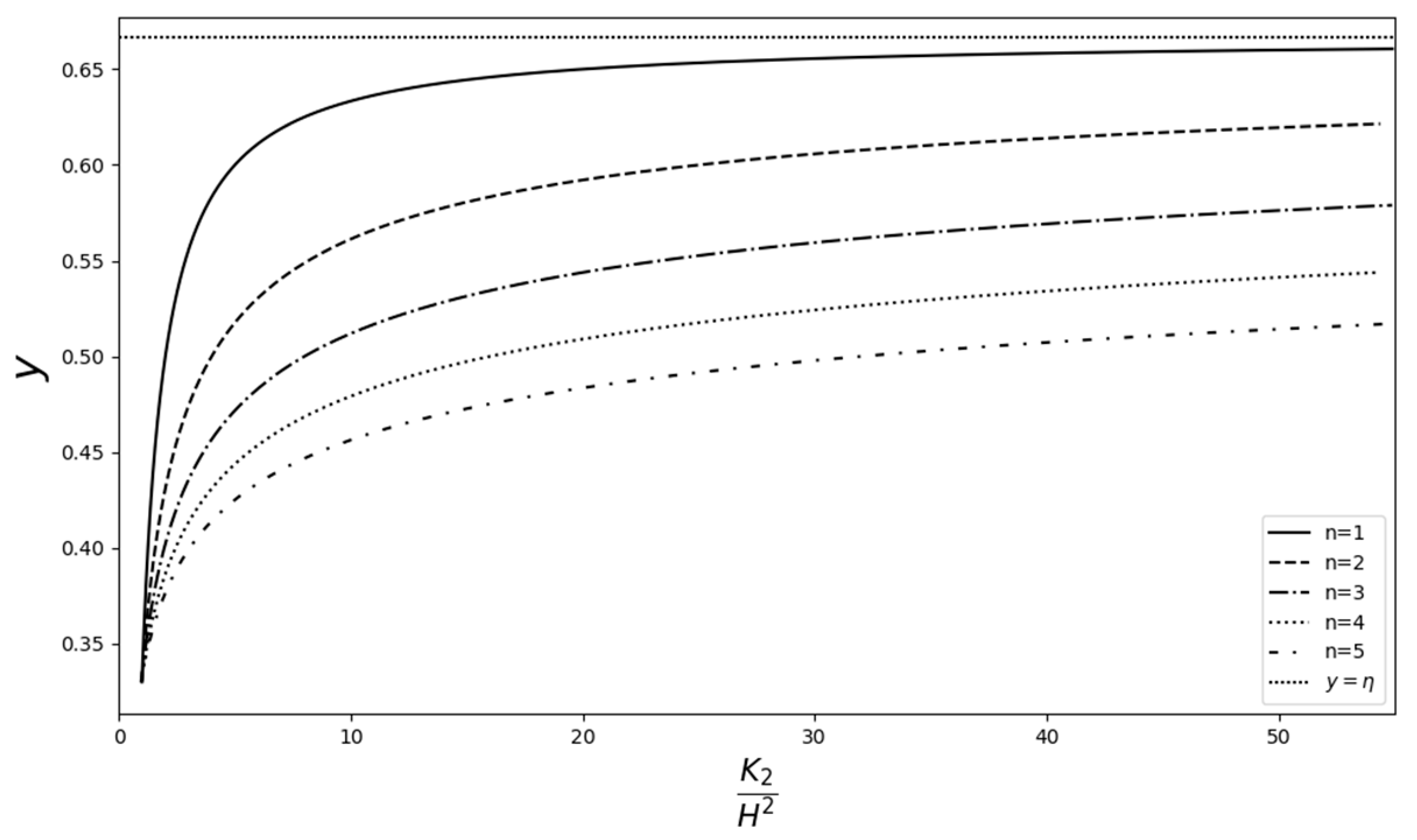
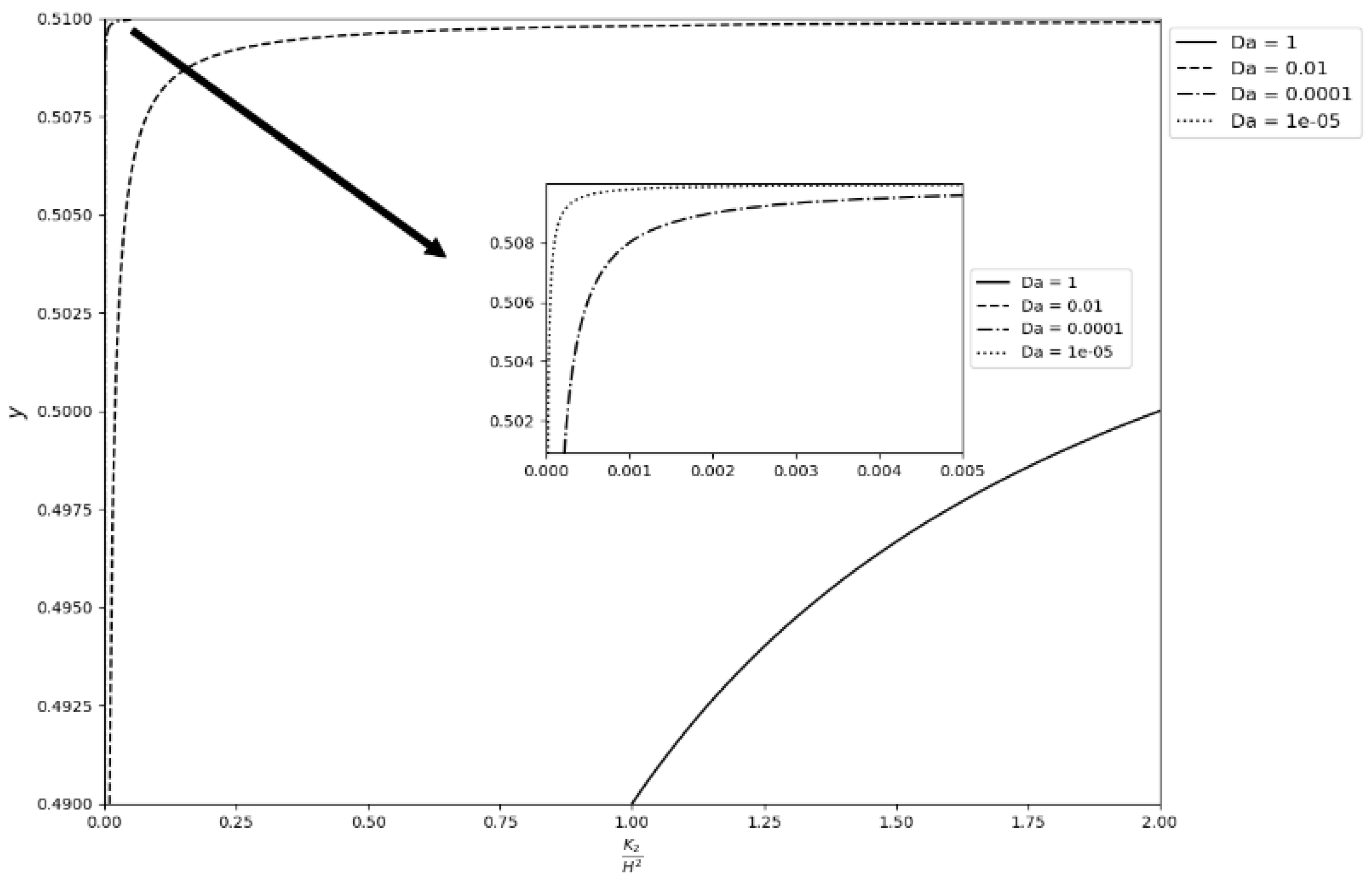
Dimensionless permeability distribution in the transition layer is given by Equation (12), namely K 2 H 2 = D a η ξ η y n . Its dependence on the values of n, Da, and the thickness of the porous layer are illustrated in Figure 2 and Figure 3, for the thick and thin transition layer, respectively, Da = 1, and various values of n. These figures demonstrate how n acts as a control parameter in the permeability distribution. Figure 4 shows the effect of Da on the permeability distribution for n = 1 and thin transition layer. The graphs are zoomed in to better illustrate the distribution when Da = 0.000001.
While there is no hard and fast rule for choosing values for n , it is recommended that the permeability expression (12) be plotted for various values of n , and a permeability profile, suitable for one’s research requirements, or a profile that minimizes permeability amplifications in the transition layer, can then be chosen.

3.2. Velocity Profiles

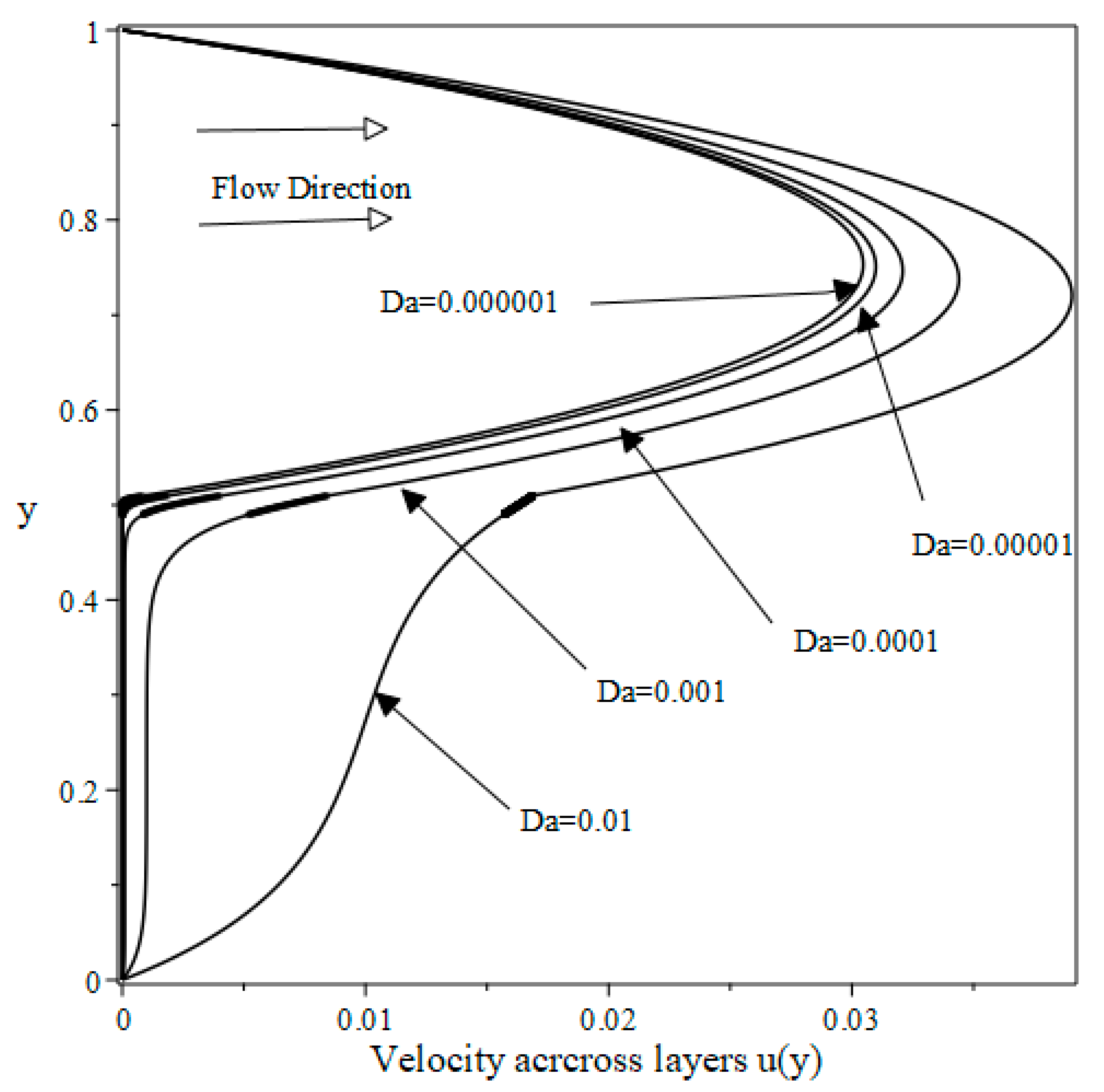
Figure 5 illustrates the velocity profiles across the three-layer flow configuration for the case of thin transition layer, n = 1, and various values of Da. The transition layer thickness is shown on the graphs as a small thick line (smudge) on each graph.
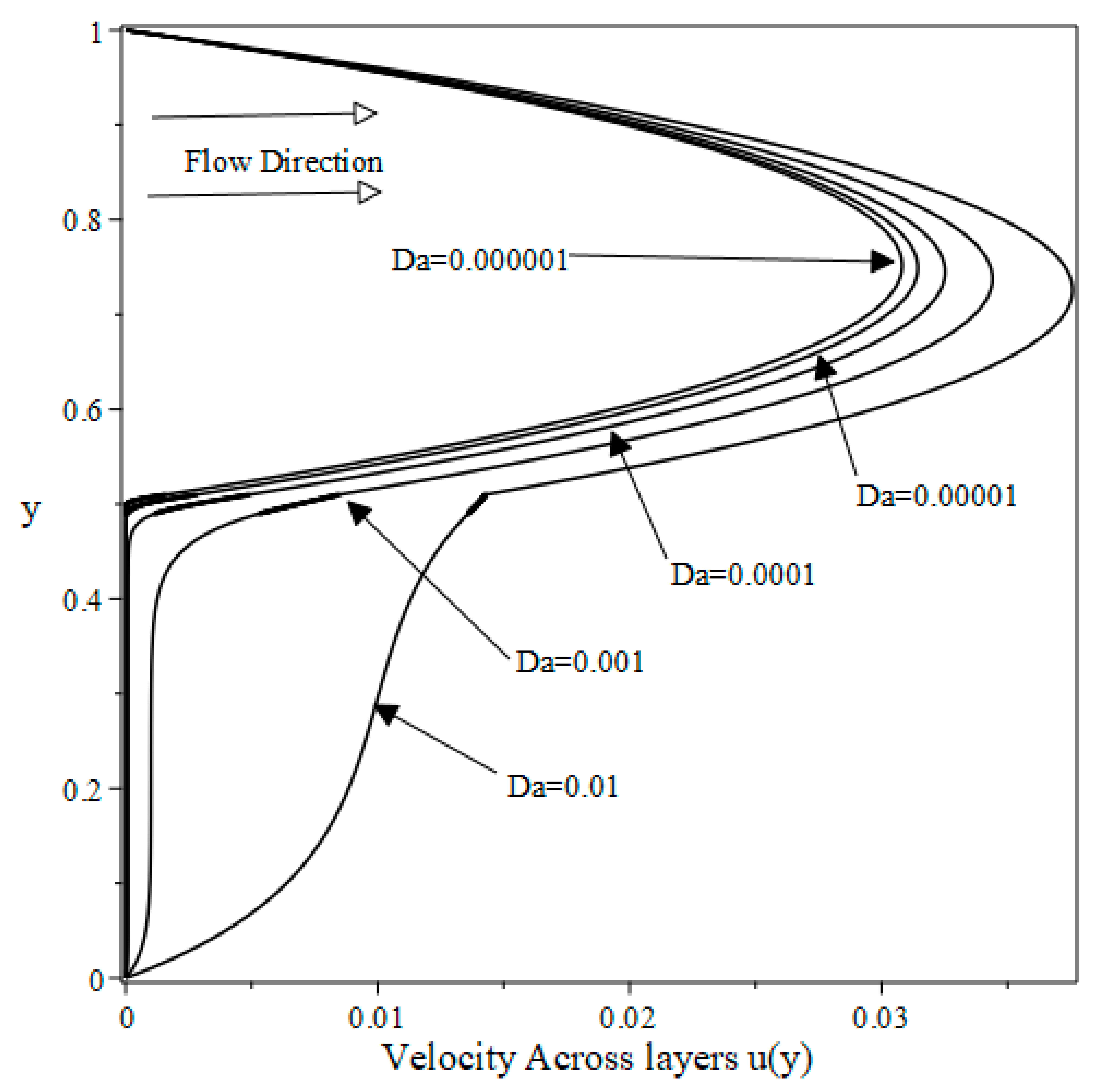
In using the solution procedure given by Equations (44)–(49), the smallest Darcy number we could compute results for was D a = 0.0000005 . However, results are shown for the smallest value of D a = 0.000001 , when n = 1 . Figure 5 shows smooth transitions from one flow domain layer to another for the range of D a used. As Da increases, the singularity at the lower interface starts creeping in (as anticipated by Nield and Kuznetsov [1]). When n = 2, Figure 6 illustrates a similar pattern of velocity profiles, and shows a more noticeable effect of the singularity at the lower interface. This emphasizes that the current model and solution procedure is more suitable for low values of Da.
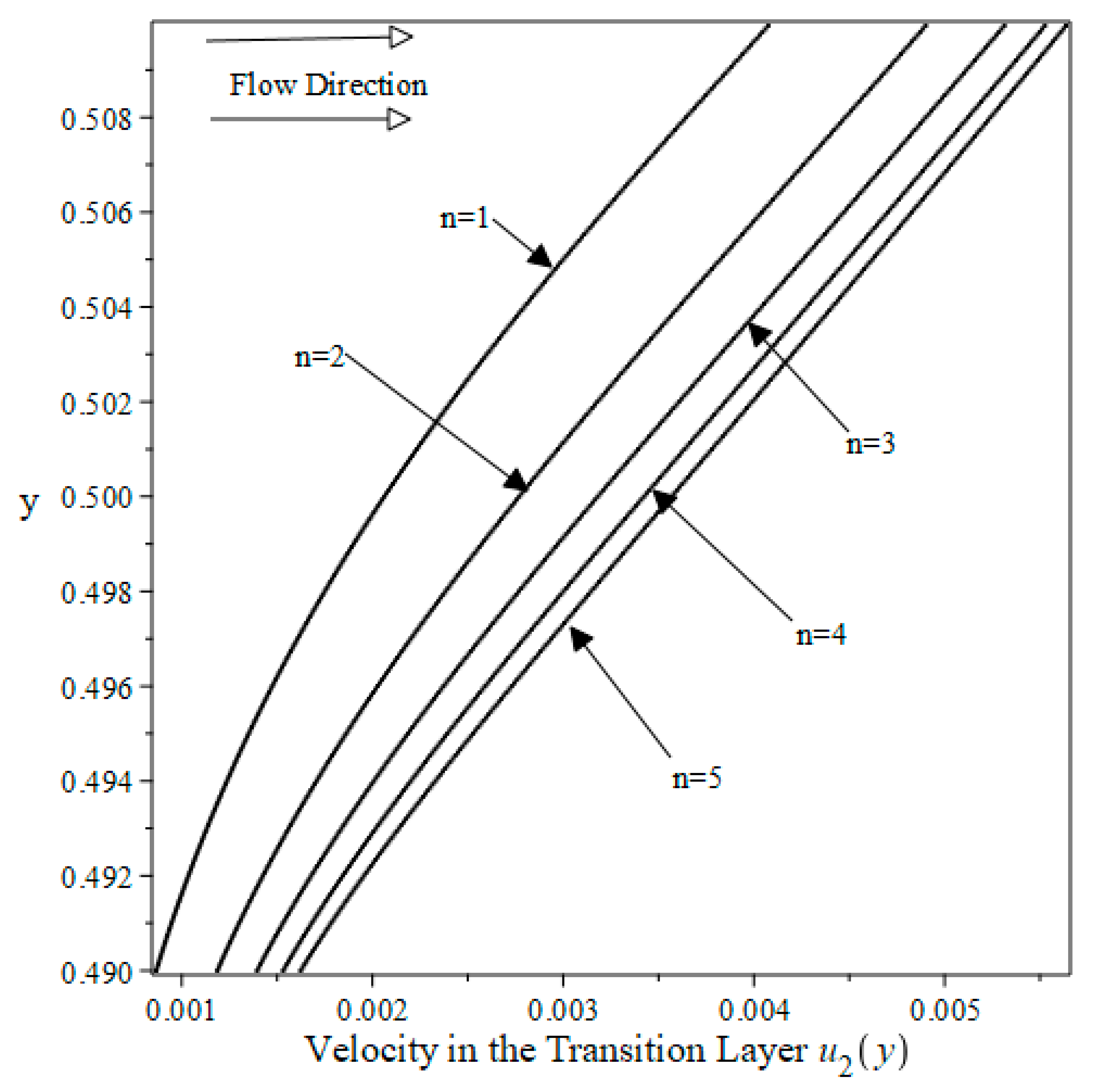
For different values of n, and a fixed value of Da, the velocity profiles are close to each other (due to graph scale) and follow a similar pattern and shape to the profiles of Figure 6. Therefore, to better demonstrate the relative magnitudes of velocities for various values of n, velocity profiles are sketched over the span of the thin transition layer 0.49 η ξ 0.51 , illustrated in Figure 7. The increase in permeability in the transition layer with increasing n is accompanied by an increase in velocity, as Figure 7 demonstrates.

3.3. Velocity at the Interfaces

At the lower and upper interfaces, y = ξ and y = η , respectively, velocity expressions are obtained from Equations (25), (26), and (38), and take the form
u 1 η = η 2 2 + c 1 η + d 1
u 2 η = c 2 A n 0 + d 2 B n 0
u 3 ξ = c 3 exp λ 3 ξ + d 3 exp λ 3 ξ + 1 M 3 λ 3 2
u 2 ξ = c 2 A n ( η ξ ) τ n + d 2 B n ( η ξ ) τ n + π 2 p sin p π M 2   ( τ n ) 2   N n ( η ξ τ n )
The velocity at the lower and upper interfaces for thick and thin transition layers, for different values of Da and different values of n, are given in Table 1 and Table 2. In Table 1, velocity at the upper interface is illustrated for the thick transition layer only, since the behavior is similar for the thin layer, for n = 1, 2, 3, and various values of Da.
As n increases, for a fixed value of Da, interfacial velocity increases since permeability increases as we approach the upper interface. This behavior is consistent for all values of Da shown. Interfacial velocity consistently increases with increasing Da for any fixed value of n, as expected.
In Table 2, velocity at the lower interface is illustrated for the thin transition layer, only, since the behavior is similar for the thick layer, for n = 1, 2, 3 and various values of Da.
As n increases, for a fixed value of Da, interfacial velocity decreases. This is due to the velocity continuity condition at the lower interface where the velocity in the homogeneous, constant permeability layer has the effect of slowing down the flow velocity at the interface.
This behavior is consistent for all values of Da shown. Interfacial velocity consistently increases with increasing Da for any fixed value of n, since Da is defined in terms of a fixed, reference permeability.
Agreement between the values computed using Equations (50) and (51) was for more than 12 significant digits, which indicates that the current formulation and computations are accurate. The same goes for using Equations (52) and (53). In Table 1 and Table 2 we retained the first 8 digits for illustration.

3.4. Shear Stress at the Interfaces

At the lower and upper interfaces, y = ξ and y = η , respectively, shear stress expressions are obtained from Equations (25), (26), and (38), and take the form
d u 1 d y ( η ) = c 1 η
d u 2 d y η = c 2 τ n A n 0 d 2 τ n B n 0
d u 3 d y ξ = c 3 λ 3 exp λ 3 ξ d 3 λ 3 exp λ 3 ξ
d u 2 d y ξ = c 2 τ n A n ( η ξ ) τ n d 2 τ n B n η ξ τ n π 2 p sin p π M 2   τ n   N n ( η ξ τ n ) .
Shear stress values at the lower and upper interfaces for different middle layer thickness, and for n = 1, 2, 3, are given in Table 3a,b, which furnish the following observations:
1-
For a given Da, the value of the shear stress at the upper interface decreases with increasing n for the thick layer. However, it increases with increasing n for the thin layer.
2-
For a given Da, the value of the shear stress at the upper interface increases with increasing n for the thin layer and decreases with increasing n for the thick layer.
3-
The thin layer experiences a higher sheer than the thick layer at the upper interface with increasing n.
4-
The thick layer experiences a higher sheer than the thin layer at the lower interface when n deviates from 1.

3.5. Mean Velocity Across the Layers

The dimensionless mean velocities across the lower and upper layers are defined, respectively, as
u ¯ 1 = η 1 u 1 d y = 1 6 η 3 1 c 1 2 η 2 1 d 1 ( η 1 )
u ¯ 3 = 0 ξ u 3 d y = c 3 λ 3 e λ 3 ξ 1 d 3 λ 3 e λ 3 ξ 1 + ξ M 3 λ 3 2
Dimensionless mean velocity in the transition layer is obtained from (38) and can be written as:
u ¯ 2 = ξ η u 2 d y = 1 τ n   ( η ξ ) τ n 0 c 2 A n t + d 2 B n t + π 2 p sin p π M 2   ( τ n ) 2   N n ( t ) d t
where t = ( η y ) τ n .
The dimensionless mean velocity across the configuration (that is, across the three layers) is defined as
u ¯ = u ¯ 1 + u ¯ 2 + u ¯ 3
and represents a measure of the overall volume flux through the channel configuration.
The above expressions are evaluated using Maple (see Appendix A) and the values are listed in for n = 1 and n = 2 in Table 4a,b for different transition layer thicknesses and Da = 1, 0.1, and 0.01, so that we can compare our results with those obtained by Nield and Kuznetsov [1]. To make the comparison, we reformulated and solved the flow problem using the same configuration as that of Nield and Kuznetsov [1]. Agreement between the results is evident from Table 4a,b.
For a given transition layer thickness and a given value of n, the total volume flux decreases with decreasing Da. This is due to flow retardation for smaller Da. For a given Da, the total volume flux increases with increasing n.

4. Conclusions

In this study, we considered the problem of flow through a free-space channel over a porous layer in the presence of a transition porous layer. This problem was treated by Nield and Kuznetsov [1] to illustrate the characteristics of the flow when the transition layer is a Brinkman layer of variable permeability, described as the reciprocal of a linear polynomial. In this study, we introduced a generalized form of the permeability function that involves the reciprocal of the nth degree of a linear polynomial. This choice of permeability function resulted in the inhomogeneous, generalized Airy differential equation. We provided the solution to the resulting differential equation in terms of a generalized Nield–Kuznetsov function, together with a computational procedure to evaluate the arising special functions. For the case of n = 1, the current problem reduces to the one considered by Nield and Kuznetsov [1], and our results agree with their results for total volume flux across the tri-layer configuration.
All computations in this work employ dimensionless quantities, while experimental data might employ physical and measurable quantities. This implies that experimental results might not be directly compared with results in this work. However, it should be quite easy to resolve the current model with actual physical data and obtain results that can be compared to experimental results. Tao et al. [3] were successful in solving the tri-layer model with the permeability model of Nield and Kuznetsov [1], while employing physical, dimensional values of parameters. A similar approach can be used for the model introduced in this work.
Highlights of this work may be stated as follows:
1-
The introduction of a generalized permeability function that provides modeling flexibility and validity for a small Darcy number, and possible control over permeability amplification in the transition layer.
2-
Obtaining the general and particular solutions to the resulting inhomogeneous, generalized Airy equation through the introduction of a generalized Nield–Kuznetsov function.
3-
Providing an evaluation procedure for the arising generalized Airy’s functions and the generalized Nield–Kuznetsov function.

Author Contributions

The authors contributed equally to this research. Conceptualization, M.H.H. and M.S.A.Z.; methodology, M.H.H. and M.S.A.Z.; software, M.S.A.Z.; validation, M.H.H. and M.S.A.Z.; formal analysis, M.H.H. and M.S.A.Z.; investigation, M.H.H. and M.S.A.Z.; resources, M.H.H.; data curation, M.S.A.Z.; writing—original draft preparation, M.H.H.; writing—review and editing, M.S.A.Z.; project administration, M.H.H. All authors have read and agreed to the published version of the manuscript.

Funding

This research received no external funding.

Data Availability Statement

All data was created using MAPLE and is included in this work.

Conflicts of Interest

The authors declare no conflicts of interest.

Appendix A

This appendix details the Maple computational procedure used to obtain the semi-analytical solution for the boundary value problem discussed in the main text. The implementation is performed using Maple 2021.0. The solution is constructed in three sub-domains with interface matching, utilizing symbolic and numerical features of Maple.
  • Software Version
All computations were performed using Maple 2021.0, developed by Maplesoft. Compatibility with this version is assumed for all syntax and function behaviors used.
Step 1: Initialize the Maple Environment and Load the Necessary Plotting Package.
Restart; with(plots):

Initialization and Parameter Definition
n := 2:          # Nonlinearity parameter
Da := 0.01:       # Darcy number
eta := 0.51:      # Right interface point
xi := 0.49:       # Left interface point
p := 1/(n + 2):    # Exponent used in similarity transformation
M2 := 1:         # Constant related to Region II
M3 := 1:         # Constant related to Region III
K := 300:         # Number of grid points for numerical output

Step 2: Compute Scaling Parameters and Constants
tau := evalf(1/(M2*Da*(eta – xi)^n)^(1/(n + 2))):
lambda3 := evalf(1/sqrt(Da)):
Define Constants Needed for Transformations and Interface Matching:
An0 := evalf(p^(1 - p)/GAMMA(1 - p)):
Bn0 := evalf(p^(1/2 - p)/GAMMA(1 - p)):
dAn0 := evalf(-p^p/GAMMA(p)):
dBn0 := evalf(-p^(p - 1/2)/GAMMA(p)):

Step 3: Define Special Functions and Their Derivatives
An := x -> evalf(2*p*sin(p*Pi)*x^(1/2)*BesselK(p, 2*p*x^(1/2/p))/Pi):
Bn := x -> evalf((p*x)^(1/2)*(BesselI(p, 2*p*x^(1/2/p)) + BesselI(-p, 2*p*x^(1/2/p)))):
dAn := x -> evalf(-2*p*sin(p*Pi)*x^(1/2*n + 1/2)*BesselK(p - 1, 2*p*x^(1/2/p))/Pi):
dBn := x -> evalf(p^(1/2)*x^(1/2*n + 1/2)*(BesselI(p - 1, 2*p*x^(1/2/p)) + BesselI(1 - p, 2*p*x^(1/2/p)))):

Step 4: Compute OF THE Integral Function Using Maple Bulid functions:
Nn := x -> evalf(An(x)*int(Bn(t), t = 0 .. x) - Bn(x)*int(An(t), t = 0 .. x)):
dNn := x -> evalf(dAn(x)*int(Bn(t), t = 0 .. x) - dBn(x)*int(An(t), t = 0 .. x)):

Step 5: Assemble and Solve Linear System

Interface Conditions Give Rise to a 6 × 6 system:
X := Matrix(6, 6, [[1, 1, 0, 0, 0, 0],
[eta, 1, -An0, -Bn0, 0, 0],
[1, 0, tau*dAn0, tau*dBn0, 0, 0],
[0, 0, An(tau*(eta - xi)), Bn(tau*(eta - xi)), -exp(lambda3*xi), -exp(-lambda3*xi)],
[0, 0, tau*dAn(tau*(eta - xi)), tau*dBn(tau*(eta - xi)), lambda3*exp(lambda3*xi), -lambda3*exp(-lambda3*xi)],[0, 0, 0, 0, 1, 1]]):

C := Vector([1/2,
eta^2/2,
eta,
1/(M3*lambda3^2) - Pi/(2*sqrt(p)*sin(p*Pi)*M2*tau^2)*Nn(tau*(eta - xi)),
-Pi/(2*sqrt(p)*sin(p*Pi)*M2*tau)*dNn(tau*(eta - xi)),
-1/(M3*lambda3^2)]):

S   : = ( X 1 ) . C:
c1 := S[1]:
d1 := S[2]:
c2 := evalf(S[3]): d2 := evalf(S[4]):
c3 := evalf(S[5]): d3 := evalf(S[6]):

Step 6: Define Piecewise Solutions
u1 := x -> -1/2*x^2 + c1*x + d1:               # Region I
u2 := x -> c2*An((eta - x)*tau) + d2*Bn((eta - x)*tau) +       # Region II
1/2*Pi*Nn((eta - x)*tau)/(sqrt(p)*sin(p*Pi)*M2*tau^2):
u3 := x -> c3*exp(lambda3*x) + d3*exp(-lambda3*x) + 1/lambda3^2: # Region III

Step 7: Numerical Evaluation and Visualization:

xvals := [seq(xi + (eta - xi)*i/K, i = 0 .. K - 1)]:
points := [seq([x, u2(x)], x in xvals)]:
P1 := plot(u1(x), x = eta .. 1, color = black):
P2 := pointplot(points, symbol = point, symbolsize = 1, color = black):
P3 := plot(u3(x), x = 0 .. xi, color = black):
P := display(P1, P2, P3):
tf := plottools:-transform((x, y) -> [y, x]):
plots:-display(tf(P), labels = [“u(y)”, “y”]):

References

  1. Nield, D.A.; Kuznetsov, A.V. The effect of a transition layer between a fluid and a porous medium: Shear flow in a channel. Transp. Porous Med. 2009, 78, 477–487. [Google Scholar] [CrossRef]
  2. Brinkman, H.C. A Calculation of the viscous force exerted by a flowing fluid on a dense swarm of particles. Appl. Sci. Res. 1947, A1, 27–34. [Google Scholar] [CrossRef]
  3. Tao, J.; Yao, J.; Huang, Z. Analysis of the laminar ow in a transition layer with variable permeability between a free-fluid and a porous medium. Acta Mech. 2013, 224, 1943–1955. [Google Scholar] [CrossRef]
  4. Nield, D.A.; Bejan, A. Convection in Porous Media, 5th ed.; Springer: New York, NY, USA, 2017. [Google Scholar]
  5. Bottaro, A. Flow over natural or engineered surfaces: An adjoint homogenization perspective. J. Fluid Mech. Perspect. 2019, 877, P1. [Google Scholar] [CrossRef]
  6. Angot, P.; Goyeau, B.; Ochoa-Tapia, J.A. A nonlinear asymptotic model for the inertial flow at a fluid-porous interface. Adv. Water Res. 2021, 149, 103798. [Google Scholar] [CrossRef]
  7. Hernandez-Rodriguez, R.; Angot, P.; Goyeau, B.; Ochoa-Tapia, J.A. Momentum transport in the free fluid-porous medium transition layer: The one-domain approach. Chem. Eng. Sci. 2022, 248, 117111. [Google Scholar] [CrossRef]
  8. Alazmi, B.; Vafai, K. Analysis of fluid flow and heat transfer interfacial conditions between a porous medium and a fluid layer. Int. J. Heat Mass Transf. 2001, 44, 1735–1749. [Google Scholar] [CrossRef]
  9. Vafai, K.; Thiyagaraja, R. Analysis of flow and heat transfer at the interface region of a porous medium. Int. J. Heat Mass Transf. 1987, 30, 1391–1405. [Google Scholar] [CrossRef]
  10. Kaviany, M. Laminar flow through a porous channel bounded by isothermal parallel plates. Int. J. Heat Mass Transf. 1985, 28, 851–858. [Google Scholar] [CrossRef]
  11. Whitaker, S. The Method of Volume Averaging, Theory and Applications of Transport in Porous Media; Kluwer Academic Publications: Dordrecht, The Netherlands, 1999; Volume 13. [Google Scholar]
  12. Bousquet-Melou, P.; Goyeau, B.; Quintard, M.; Fichot, F.; Gobin, D. Average momentum equation for interdentritic flow in a solidifying columnar mushy zone. Int. J. Heat Mass Transf. 2002, 45, 3651–3665. [Google Scholar] [CrossRef]
  13. Angot, P.; Goyeau, B.; Ochoa-Tapia, J.A. Asymptotic modeling of transport phenomena at the interface between a fluid and a porous layer: Jump conditions. Phys. Rev. E 2017, 95, 063302. [Google Scholar] [CrossRef]
  14. Kashkuli, S.; Mahjoob, S.; Vafai, K. Numerical analysis of liquid jet impingement through confined uniform cooling channels employing porous metal foams. Transp. Porous Med. 2025, 152, 13. [Google Scholar] [CrossRef]
  15. Goyeau, B.; Lhuillier, D.; Velarde, M.G. Momentum transport at a fluid-porous interface. Int. J. Heat Mass Transf. 2003, 46, 4071–4081. [Google Scholar] [CrossRef]
  16. Beavers, G.S.; Joseph, D.D. Boundary conditions at a naturally permeable wall. J. Fluid Mech. 1967, 30, 197–207. [Google Scholar] [CrossRef]
  17. Nield, D.A. The Beavers–Joseph boundary condition and related matters: A historical and critical note. Transp. Porous Med. 2009, 78, 537–540. [Google Scholar] [CrossRef]
  18. Ehrhardt, M. An Introduction to Fluid-Porous Interface Coupling; Weierstrass Institute for Applied Analysis and Stochastics: Berlin, Germany, 2010. [Google Scholar]
  19. Rudraiah, N. Coupled parallel flows in a channel and a bounding porous medium of finite thickness. J. Fluids Eng. ASME 1985, 107, 322–329. [Google Scholar] [CrossRef]
  20. Rudraiah, N. Flow past porous layers and their stability. In Encyclopedia of Fluid Mechanics, Slurry Flow Technology; Gulf Publishing: Houston, TX, USA, 1986; pp. 567–647. [Google Scholar]
  21. Hill, A.A.; Straughan, B. Poiseuille flow in a fluid overlying a porous medium. J. Fluid Mech. 2008, 603, 137–149. [Google Scholar] [CrossRef]
  22. Sahraoui, M.; Kaviany, M. Slip and no-slip velocity boundary conditions at interface of porous, plain media. Int. J. Heat Mass Transf. 1992, 35, 927–943. [Google Scholar] [CrossRef]
  23. Jamet, D.; Chandesris, M. Boundary conditions at a planar fluid-porous interface for a Poiseuille flow. Int. J. Heat Mass Transf. 2006, 49, 2137–2150. [Google Scholar]
  24. Jamet, D.; Chandesris, M. Boundary conditions at a fluid-porous interface: An a priori estimation of the stress jump coefficients. Int. J. Heat Mass Transf. 2007, 50, 3422–3436. [Google Scholar]
  25. Parvazinia, M.; Nassehi, V.; Wakeman, R.J.; Ghoreishy, M.H.R. Finite element modelling of flow through a porous medium between two parallel plates using the Brinkman equation. Transp. Porous Med. 2006, 63, 71–90. [Google Scholar] [CrossRef]
  26. Neale, G.; Nader, W. Practical significance of Brinkman’s extension of Darcy’s law: Coupled parallel flows within a channel and a bounding porous medium. Can. J. Chem. Eng. 1974, 52, 475–478. [Google Scholar] [CrossRef]
  27. Ochoa-Tapia, J.A.; Whitaker, S. Momentum transfer at the boundary between a porous medium and a homogeneous fluid: I) Theoretical Development. Int. J. Heat Mass Transf. 1995, 3, 2635–2646. [Google Scholar] [CrossRef]
  28. Ochoa-Tapia, J.A.; Whitaker, S. Momentum transfer at the boundary between a porous medium and a homogeneous fluid: II) Comparison with experiment. Int. J. Heat Mass Transf. 1995, 3, 2647–2655. [Google Scholar] [CrossRef]
  29. Roach, D.C.; Hamdan, M.H. Interfacial velocities, slip Parameters and other theoretical expressions arising in the Beavers and Joseph condition. WSEAS Trans. Fluid Mech. 2022, 17, 68–78. [Google Scholar] [CrossRef]
  30. Vafai, K. Analysis of the channeling effect in variable porosity media. ASME J. Energy Resour. Technol. 1986, 108, 131–139. [Google Scholar] [CrossRef]
  31. Nield, D.A. The boundary correction for the Rayleigh-Darcy problem: Limitations of the Brinkman equation. J. Fluid Mech. 1983, 128, 37–46. [Google Scholar] [CrossRef]
  32. Nield, D.A. The limitations of the Brinkman-Forchheimer equation in modeling flow in a saturated porous medium and at an interface. Int. J. Heat Fluid Flow 1991, 12, 269–272. [Google Scholar] [CrossRef]
  33. Morad, M.R.; Khalili, A. Transition layer thickness in a fluid-porous medium of multi-sized spherical beads. Exp. Fluids 2009, 46, 323–330. [Google Scholar] [CrossRef]
  34. Goharzadeh, A.; Khalili, A.; Jorgensen, B.B. Transition layer thickness at a fluid-porous interface. Phys. Fluids 2005, 17, 057102. [Google Scholar] [CrossRef]
  35. Duma, T.; Shavit, U. A solution of the laminar ow for a gradual transition between porous and fluid domains. Water Resour. Res. 2010, 46, 09517. [Google Scholar]
  36. Rees, D.A.S.; Pop, I. Vertical free convection in a porous medium with variable permeability effects. In. J. Heat Mass Transf. 2000, 43, 2565–2571. [Google Scholar] [CrossRef]
  37. Siginer, D.A.; Bakhtiyarov, S.I. Flow in porous media of variable permeability and novel effects. J. Appl. Mech. 2001, 68, 312–319. [Google Scholar] [CrossRef]
  38. Roach, D.C.; Hamdan, M.H. On the Sigmoid function as a variable permeability model for Brinkman equation. WSEAS Trans. Appl. Theor. Anal. (WSEAS) 2022, 17, 29–38. [Google Scholar] [CrossRef]
  39. Hamdan, M.H.; Kamel, M.T. On the Ni(x) integral function and its application to the Airy’s non homogeneous equation. Appl. Math. Comput. 2011, 21, 7349–7360. [Google Scholar] [CrossRef]
  40. Abu Zaytoon, M.S.; Hamdan, M.H. Weber equation model of flow through a variable permeability porous core bounded by fluid layers. J. Fluids Eng. Trans. ASME 2022, 144, 041302. [Google Scholar] [CrossRef]
  41. Swanson, C.A.; Headley, V.B. An extension of Airy’s equation. SIAM J. Appl. Math. 1967, 15, 1400–1412. [Google Scholar] [CrossRef]
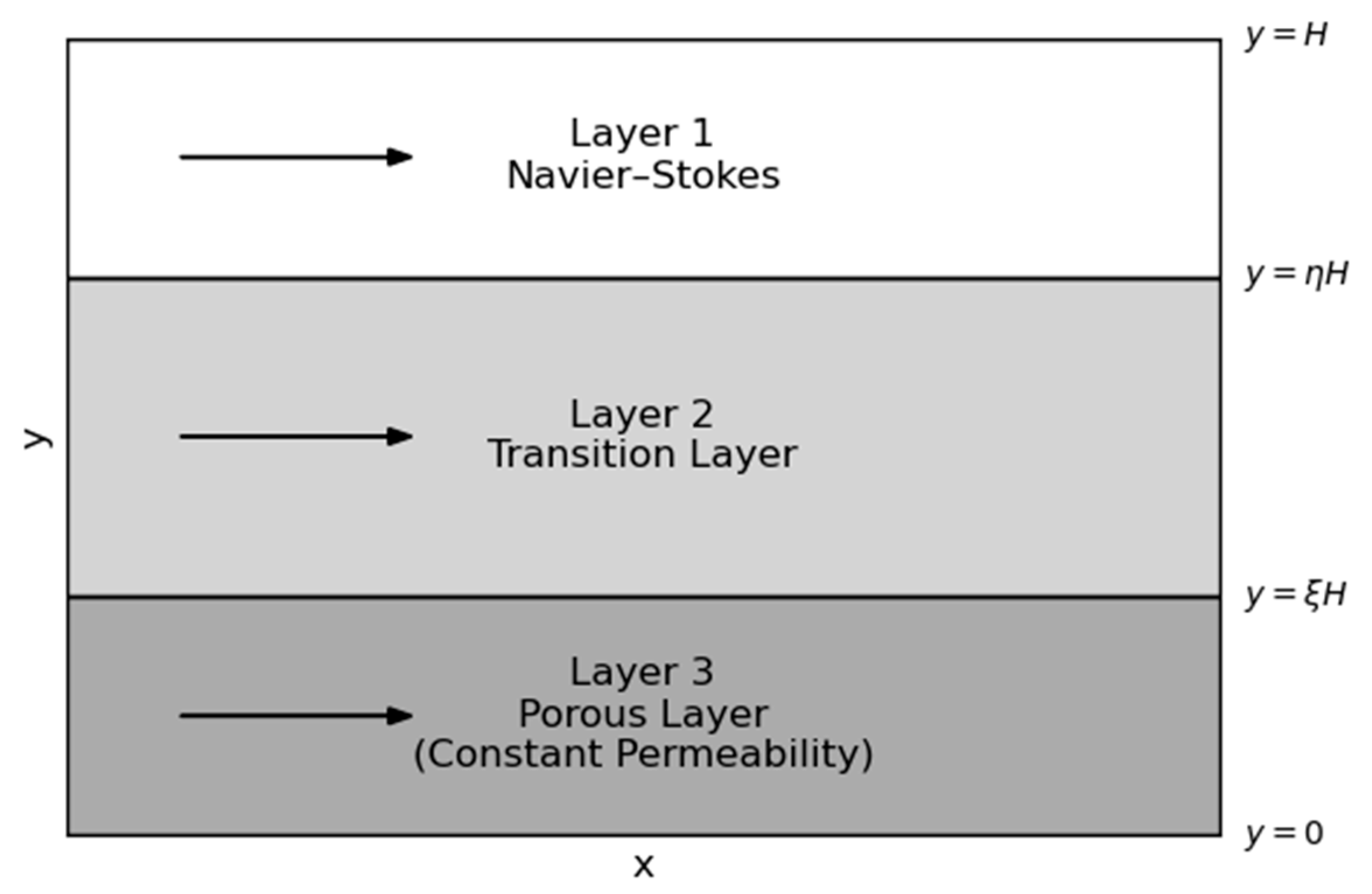
Figure 1. Representative sketch of a tri-layer channel.
Fluids 10 00151 g001
Figure 2. Dimensionless permeability distribution. Thick layer; Da = 1; n = 1, 2, 3, 4, 5.
Fluids 10 00151 g002
Figure 3. Dimensionless permeability distribution. Thin layer; Da = 1; n = 1, 2, 3, 4, 5.
Fluids 10 00151 g003
Figure 4. Dimensionless permeability distribution. Thin layer; n = 1; various values of Da.
Fluids 10 00151 g004
Figure 5. Dimensionless velocity profiles in the thin layer. n = 1 and low values of Da.
Fluids 10 00151 g005
Figure 6. Dimensionless Velocity Profiles in the Thin Layer. n = 2 and low values of Da.
Fluids 10 00151 g006
Figure 7. Dimensionless velocity profiles in the thin transition layer. Da = 0.0001 and various values of n.
Fluids 10 00151 g007
Table 1. Dimensionless velocity at the upper interface for thick layer.
n u 1 η = u 2 ( η ) Da = 0.01Da = 0.001Da = 0.0001Da = 0.00001
1 u 1 η = u 2 ( η ) 0.021149940.012332740.006497200.00321735
2 u 1 η = u 2 ( η ) 0.024866390.017389990.011331480.00699674
3 u 1 η = u 2 ( η ) 0.026733160.020509630.014981830.01049763
Table 2. Dimensionless velocity at the lower interface for thin layer.
n u 3 ξ = u 3 ( ξ ) Da = 0.01Da = 0.001Da = 0.0001Da = 0.00001
1 u 2 ξ = u 3 ( ξ ) 0.015704510.005216850.000865810.00002779
2 u 2 ξ = u 3 ( ξ ) 0.013594400.0053362970.00118670.00006497
3 u 2 ξ = u 3 ( ξ ) 0.012177740.005269910.001395040.00011395
Table 4. (a). Mean velocity across the channel for thick layer, n = 1, 2 and different Da. (b). Mean velocity across the channel for thin layer, n = 1, 2 and different Da. * Results obtained by Nield and Kuznetsov [1].
(a)
n = 10.07939500
0.0794 *
0.056926820.02071123
0.0207 *
n = 20.087441410.064036060.02670879
(b)
n = 10.07940428
0.0794 *
0.057351280.02355505
0.0236 *
n = 20.079459510.057593420.0238459
Table 3. (a) Shear stress at the upper interface. (b) Shear stress at the lower interface.
(a)
Da = 0.01
Thin Layer
Da = 0.01
Thick Layer
n = 10.210533240.10321682
n = 20.215855930.09206747
n = 30.219405780.08646717
(b)
Da = 0.01
Thin Layer
Da = 0.01
Thick Layer
n = 10.058540850.02721478
n = 20.037437390.04813607
n = 30.023269290.06526954
Disclaimer/Publisher’s Note: The statements, opinions and data contained in all publications are solely those of the individual author(s) and contributor(s) and not of MDPI and/or the editor(s). MDPI and/or the editor(s) disclaim responsibility for any injury to people or property resulting from any ideas, methods, instructions or products referred to in the content.