Article

A Method for Measuring the Rheology of a Non-Newtonian Fluid Based on the Analysis of the Recirculation Angle of Secondary Flows in a Curved U-Shaped Channel

by
Alexander S. Lobasov
1,2,
Andrey V. Minakov
1,2 and
Sergey A. Filimonov
1,2,*
1
School of Engineering Physics and Radio Electronics, Siberian Federal University, 660074 Krasnoyarsk, Russia
2
Kutateladze Institute of Thermophysics SB RAS, 630090 Novosibirsk, Russia
*
Author to whom correspondence should be addressed.
Fluids 2025, 10(3), 65; https://doi.org/10.3390/fluids10030065
Submission received: 21 December 2024 / Revised: 21 February 2025 / Accepted: 6 March 2025 / Published: 8 March 2025

Abstract

:
The field of hydrodynamics, specifically microfluidics, is currently undergoing rapid development, with significant progress being made in the creation of new devices and technologies that outperform their macroscopic counterparts. Concurrently, determining the parameters of a non-Newtonian fluid is becoming an important task in many areas of industry and production, particularly in the oil industry. Both the drilling fluids (needed to create wells) and the polymer-based displacers and surfactants (needed to extract oil) have non-Newtonian properties. This paper presents a method for determining the indices of consistency and flow behaviour of the non-Newtonian fluid (power-law model) based on the analysis of secondary Dean vortices generated in a curved channel. This phenomenon is conveniently described using the recirculation angle. The structure of the flow of non-Newtonian fluids in a U-shaped micromixer has been studied. The dependence of the recirculation angle on the fluid flow rate was obtained for different fluid parameters. A universal correlation was proposed to describe the dependence of the inverse Dean number on the recirculation angle of the flow. The consistency and flow behaviour indices of the power-law model of non-Newtonian fluids found using the above correlation can be measured in the experiments.

1. Introduction

Currently, for various reasons, there is revolutionary development of microsystem technology for various purposes. Microsystem technology has obvious advantages (energy efficiency and low material consumption) and has been actively used in a wide variety of applications: when creating new computer equipment samples, in various biomedical technologies, and in the pharmaceutical and chemical industries, etc. A significant part of microsystem equipment is, either way, connected with the flows of liquids and gases in microchannels. Fluid flows in microchannels are characterized by the significant influence of capillary forces and wall effects on flow regimes and heat and mass transfer processes. Under these conditions, modes uncommon for large diameter channels are implemented. Microchannels with dimensions of about 100 μm are now widely used in micro-heat exchangers for cooling electronics, in microreactors for the highly efficient synthesis of chemical products, in medicine and pharmaceuticals as laboratories on a chip, and in the production of new medicines, etc. Fluid flows in microchannels are also widespread in nature. These are the processes of substance transport in plants and living organisms, the multiphase filtration of fluids in microporous reservoirs of oil and gas, and much more. The variety of microchannel applications has lead to a large number of studies on this topic. A new interdisciplinary science, microfluidics, has emerged to describe the behaviour of flows of liquids and gases in microscopic channels, with their sizes ranging from 100 nm to 500 μm.
The mixing of fluids is the basic process in most microfluidic devices (chemical microreactors, analyzers of chemical and biological substances, drug transport systems, and microfluidic heat exchangers, etc.) [1,2,3,4,5,6,7,8,9,10,11,12,13,14,15,16,17,18,19,20,21,22,23,24,25,26,27,28,29,30,31,32,33,34,35,36]. In macroscopic flows, mixing usually occurs in a turbulent mode. However, in microfluidic devices, the flows are usually laminar, and mixing there is limited by molecular diffusion. In order to intensify mixing, special devices—micromixers—are used. Micromixers are one of the key elements of many micro- and nanoelectromechanical systems (MEMS and NEMS). To date, a large number of different micromixers have been developed. There are passive and active ways to intensify mixing in micromixers (e.g., reviews [1,2,3,4,5,6] as well as monographs [34,35,36]). In passive mixers, mixing intensification is achieved by increasing the residence time of the mixture in the mixer, or the geometric features of the mixing channel (inserts, bends, and constrictions, etc.). According to these principles, passive micromixers are divided into parallel mixing micromixers (T- and Y-shaped microchannels), sequential mixing micromixers, focusing micromixers, and mixers with chaotic mixing. In addition, active mixers have recently become widespread. Active mixers superimpose some external disturbances (acoustic, electric, or magnetic vibrations, etc.) upon the flow. One of the widely used methods of active mixing is to set flow pulsations at the inlet to the mixer.
Despite the huge practical interest and significant number of works in this field, the structure and properties of flows in micromixers have been studied insufficiently. Experimental studies on mixing processes in micromixers in the vast majority of cases are limited to the visual observation of the mixing pattern when varying certain parameters. Only in recent years have works actively employing modern micro-PIV and micro-LIF methods to study the local characteristics of flow and mixing in microchannels appeared. Due to the extremely small size of the channels and the difficulties in ensuring optical access to them, the widespread use of these methods to study the structure of flows in microflows is limited. At the same time, in order to optimize the mixing process in microfluidic mixers, there is a need for detailed information about the flow structure and flow modes. For these purposes, computational fluid dynamics (CFDs) methods are actively used to optimize the operation of micromixers. In accordance with the literature review, numerical modelling has become the main tool in the field [1,2,3,4,5,6,7,8,9,10,11,12,13,14,15,16]. The Reynolds numbers are usually small, and the flows are laminar in most cases. However, despite the small size of the channels, turbulent flows also occur in microfluidic devices [11,12]; their modelling is realized with direct numerical simulation (DNS) methods. Notably, at relatively high values of Reynolds numbers (of the order of 1000), a number of new interesting phenomena occur in microchannels; they should be further studied both from a fundamental point of view and for practical purposes (e.g., our works [23,24,25,26,27]). A large number of works have been devoted to the optimization of certain types of micromixers [17,18,19,20,21,22]. Over the past fifteen years, various ways to intensify mixing in microfluidic mixers have been considered, including by complicating the geometric shape of the mixing channel. At the same time, despite all the variety in passive mixers, the most widespread ones are micromixers based on the following principles of mixing intensification: diffusion (mixing in long channels), alternate separation and fusion of flows, chaotic advection, and vortex mixing (Dean vortices, etc.).
As mentioned above, micromixers are the main components in any complex microfluidic device. In analytical chemistry, microfluidics have given rise to a laboratory on a chip (lab-on-a-chip)—a microfluidic device that allows for several multistage chemical analyses on a single microchip [37]. This also includes the concept of µTAS (miniaturized total analysis system), which involves examining a sample in the immediate vicinity of the production site using various sensors integrated on a single microchip (chromatography, pH, zeta potential, spectroscopy, and PVT analysis, etc.) [38]. The ultimate goal of these approaches is to combine all the functions of a chemical laboratory in a single microfluidic chip. In addition, microchannel technologies are widely used in chemistry [38,39,40] for the precise chemical synthesis of substances on flow-through microreactors with high specific velocity, studies of the kinetics of chemical reactions under conditions close to an ideal mixing reactor, obtaining complex emulsions and dispersed systems with encapsulated droplets of immiscible fluids, the filtration of chemical synthesis products, obtaining gas microbubbles and foams, and conducting catalytic reactions with a catalyst applied to the walls of microchannels, in particular, for the synthesis of liquid hydrocarbons from natural gas, etc.
It is a common phenomenon that the fluids employed in such systems frequently demonstrate non-Newtonian properties. Illustrative examples encompass drilling fluids, polymer-based displacers and surfactants in the oil and gas industry, along with numerous biological fluids, including blood, lymph, cerebrospinal, and intercellular fluid and cell cytoplasm, etc. Consequently, a significant proportion of the scientific literature is dedicated to the investigation of the flow and mixing of non-Newtonian fluids, in addition to their properties and the mutual influence they exert on each other [41,42]. A number of papers have been published that discuss the flows inside channels and flows around bodies at very low Reynolds numbers [43,44]. Other papers discuss the flow of concrete [45,46] and the heat transfer of waxy crude oil [47]. Furthermore, there are papers that discuss the flow and mixing of such fluids in microchannels [48,49,50] and micromixers [30,51,52]. Furthermore, studies pertaining to the properties of non-Newtonian fluids, along with the development of rheometers for the purpose of their analysis, assume equal significance [53,54,55].
In the present study [56], the novel concept of measuring the viscosity of Newtonian fluids is proposed and validated. This is achieved by analyzing the behaviour of Dean vortices in a 180-degree curved microfluidic channel. Additionally, the hypothesis was formulated that this rheometer could also be utilized to measure the properties of non-Newtonian fluids. The development of such a microfluidic rheometer requires a detailed study of the flow structure features in the curved channels of non-Newtonian media. In this regard, this work systematically investigates the influence of fluid flow and rheological parameters on the flow regimes of a non-Newtonian viscoelastic fluid in a U-shaped microchannel, as well as on the flow structure and behaviour of Dean vortices in the channel. This is achieved through the use of numerical modelling (CFDs).

2. Numerical Procedure

2.1. Basic Assumptions and Governing Equations

Computational fluid dynamics (CFDs) methods are used as the main approach to solving the tasks. This paper considers the incompressible flows of multicomponent fluids, which are described using a hydrodynamic approach. Within the framework of this approach, microflows are modelled by solving a system of Navier–Stokes equations:
ρ t + ( ρ v ) = 0 ,   ρ v t + ( ρ v v ) = P + τ ,
where ρ is the density of the fluid, P is the pressure, v is its velocity, and τ is the viscous stress tensor.
To model non-Newtonian flows, this work uses a well-known approach [30,57,58], in which the medium is considered a non-linear viscous fluid with the introduction of the effective viscosity of the fluid μ ( γ ˙ ) , generally depending on the shear rate. In this case, the viscous stress tensor is defined as τ = μ ( γ ˙ )   ε , and the shear rate γ ˙ is the second invariant of the strain rate tensor:
γ ˙ = 1 2 i j ε i ε j                     ε i j = u i x j + u j x i .
Here, ui,j are the components of the velocity vector.
The medium under consideration can be either a viscous Newtonian fluid or a non-Newtonian viscoplastic fluid, with its behaviour described by the most common rheological model of a power-law fluid. Depending on the rheology of the medium, the effective viscosity has the following form:
μ γ ˙ = k for a Newtonian medium (k is the molecular viscosity of the fluid);
μ γ ˙ = k γ ˙ n 1 for a power-law model, where n and k are the coefficients of the model (consistency index and flow behaviour index, respectively).
The viscosity and density of the mixture are determined through the mass fraction of the components of the mixture f and the molecular viscosities μ1,2, as well as the partial densities ρ1,2 of the pure components:
μ = f   μ 1 + 1 f   μ 2                     1 ρ = f ρ 1 + 1 f ρ 2 ,
with the evolution of mass concentrations being determined by the following equation:
ρ f t + ρ f v = ρ D f .
The no-slip conditions were used as boundary conditions on the channel walls for the velocity vector components. The applicability of this type of boundary condition for channels of the order of 50 μm is shown in [21,22,23,24,25,26,27,28,29,30,31,32,33,34,35,36].
An unstructured three-dimensional grid (Figure 1) consisting of 1,000,000 nodes was used for calculations. A preliminary study of the effect of the numerical grid refinement was performed. The considered refinement is shown to be sufficient to obtain a convergent solution.
Systematic computational studies of the mixing processes of two non-Newtonian fluids in a U-shaped microchannel have been carried out. The channel width was w = 920 μm, its height was h = 500 μm, and the radius of curvature was 1 cm. The influence of the flow rate of fluids, the consistency index, and the flow behaviour index was investigated. The flow rates of fluids at the inputs were set equally and ranged from 2 mL/min to 20 mL/min. The consistency index ranged from 0.006 Pa·sn to 0.6 Pa·sn, and the flow behaviour index ranged from 0.4 to 0.8.

2.2. The Numerical Method

To solve the system of equations described above, a software package Ansys Fluent 2021 R2 for computational fluid dynamics problems was used. A detailed description of the numerical algorithm is given in the works [24,25,31,32,57], and further, the main issues of the numerical methodology are set forth. The difference analogue of the convective diffusion Equations (1) and (2) is found using the finite volume method [59,60,61] for structured multiblock grids. In this case, the resulting scheme automatically turns out to be conservative. The essence of the method is to divide the computational domain into control volumes and integrate the initial conservation equations for each of them to obtain finite difference ratios. The approximation of the convective terms of the transport Equations (1) and (2) is made using the second-order upwind schemes QUICK [62] and TVD [61], respectively. An implicit second-order scheme is used to approximate the nonstationary terms of the equations of hydrodynamics. Diffusion flows and source terms are approximated by finite volume analogues of the central difference relations with the second order of accuracy. The connection between the velocity and pressure fields, which ensures the fulfilment of the continuity equation, is realized using the SIMPLEC procedure on combined grids [59]. To eliminate pressure field oscillations, the Rhie–Chow approach is used. The monotonizer is to be introduced into the equations for pressure correction [63] in this approach. The difference equations obtained as a result of discretization of the initial system of differential equations are solved iteratively using an algebraic multigrid solver [64].

3. Results and Discussion

The study considered a curved U-shaped microchannel, with a height h and a width w. The flow in such a microchannel is described by the Reynolds and Dean numbers. Despite numerous studies of the rheological properties of non-Newtonian fluids, there is still no single way to determine a characteristic as basic as the Reynolds number. The most common formula is as follows:
Re = ρ u 2 n d h n k
where u is the velocity of the fluid and dh is the hydraulic diameter of the channel. The latter is a characteristic number that depends on the geometry of the channel cross-section and is determined by the formula:
d h = 4 S P ,
where S = w·h and P = 2·(w + h) are the cross-sectional area and the perimeter of the channel, respectively.
The Dean number is a criterion of similarity in hydrodynamics, expressing the ratio of the transverse fluid flow, arising from the curvature of the channel, to the longitudinal flow:
De = Re d h 2 R ,
where R represents the curvature of the channel.
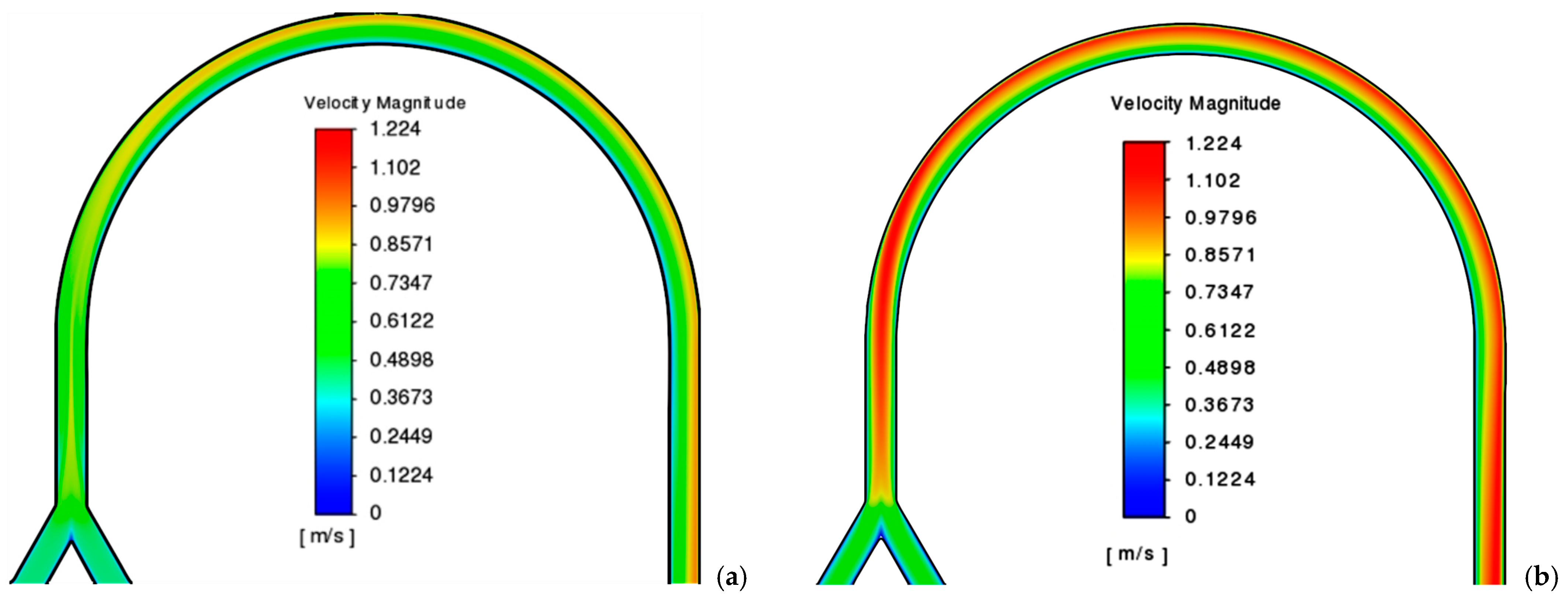
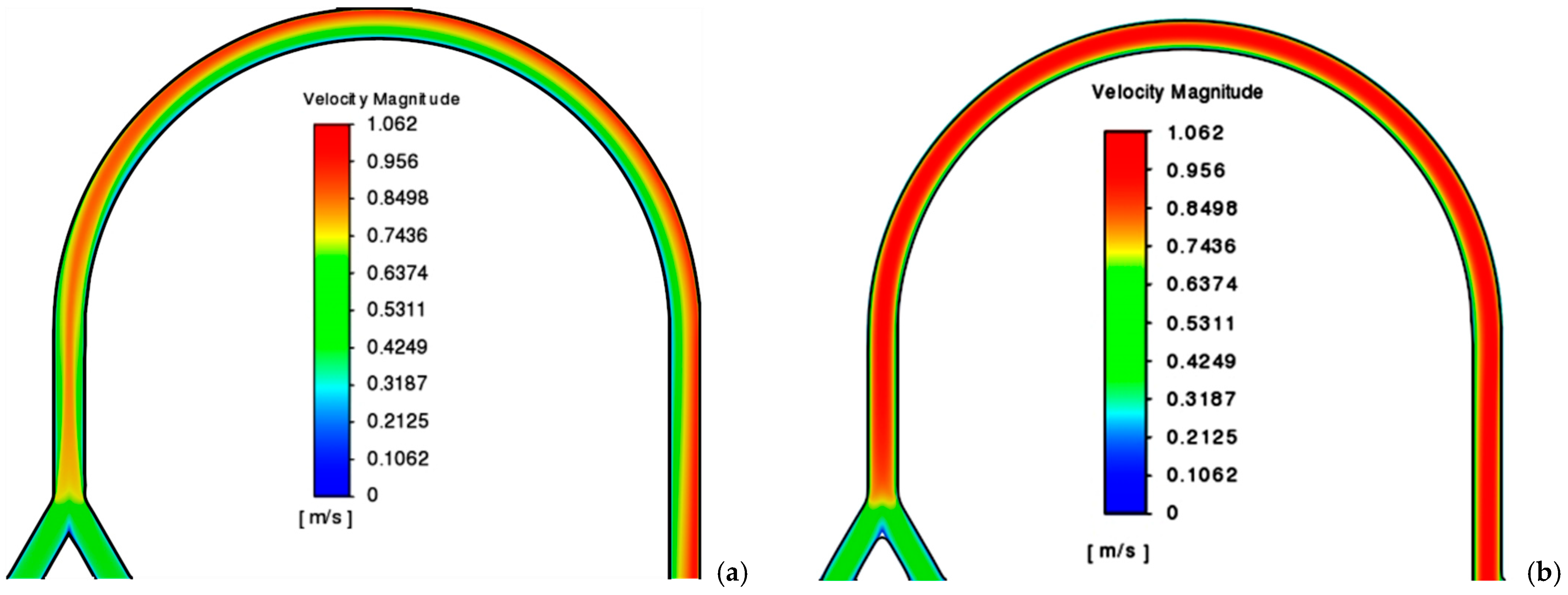
In this paper, the flow of two power-law fluids with the following parameters have been studied: the consistency index set to 0.006 Pa·sn, 0.06 Pa·sn, and 0.6 Pa·sn and the flow behaviour index set to 0.4, 0.6, and 0.8. The flow rates for both fluids at the inlet were the same and equal to 2 mL/min, 10 mL/min, and 20 mL/min. As a result of calculations, distributions of the velocity modulus in the central longitudinal section of the channel were obtained and shown for individual cases in Figure 2, Figure 3 and Figure 4. Apparently, the shape of the fluid flow in the U-shaped channel is influenced by both the parameters of the fluid and its flow rate. From these figures, it can be seen that an increase in the flow rate leads to the formation of a converging flow in the area of the merging of two fluids, as well as to a more uniform distribution of velocity over the channel width. An increase in the flow behaviour index affects the distribution of the velocity modulus non-linearly, namely, its maximum heterogeneity is observed for a value of n = 0.6, which decreases at a value of n = 0.8, and the most uniform distribution is established for n = 0.4. The effect of the consistency index is also non-linear. Thus, when it increases from a value of 0.006 Pa·sn to a value of 0.06 Pa·sn, a pronounced central jet is formed at the beginning of the channel to later press against the outer wall, and at k = 0.6 Pa·sn, a velocity distribution is observed to be almost identical to the flow in the non-curved channel.
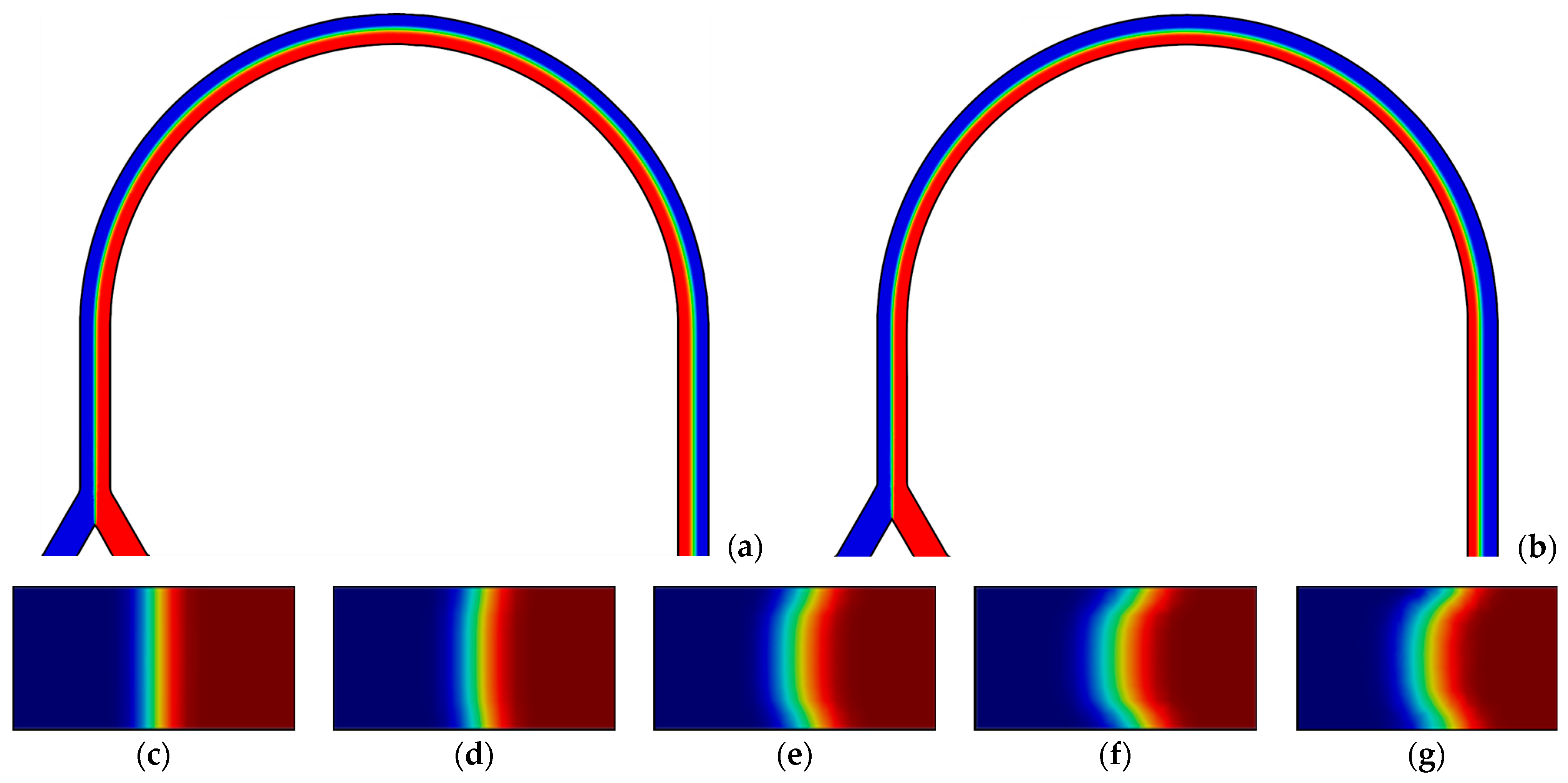
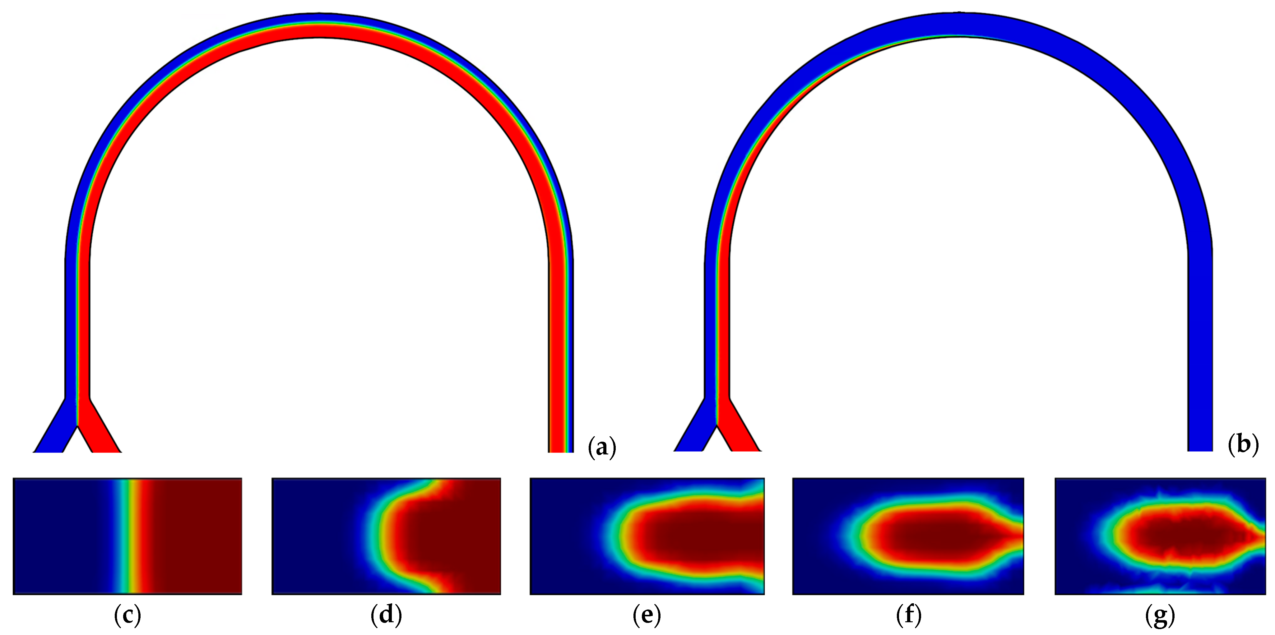
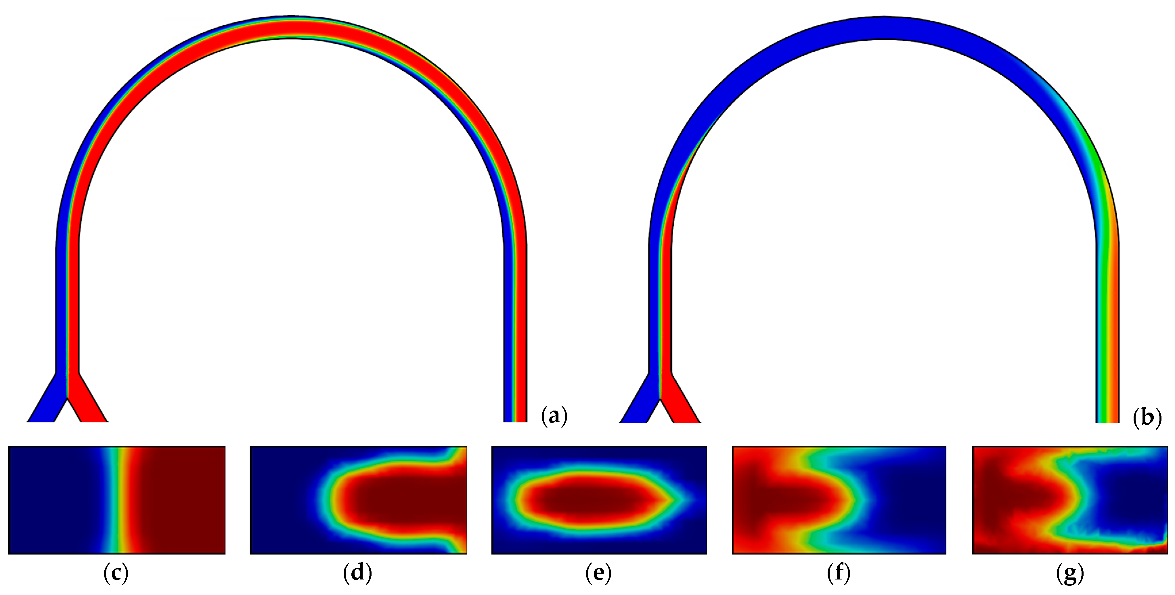
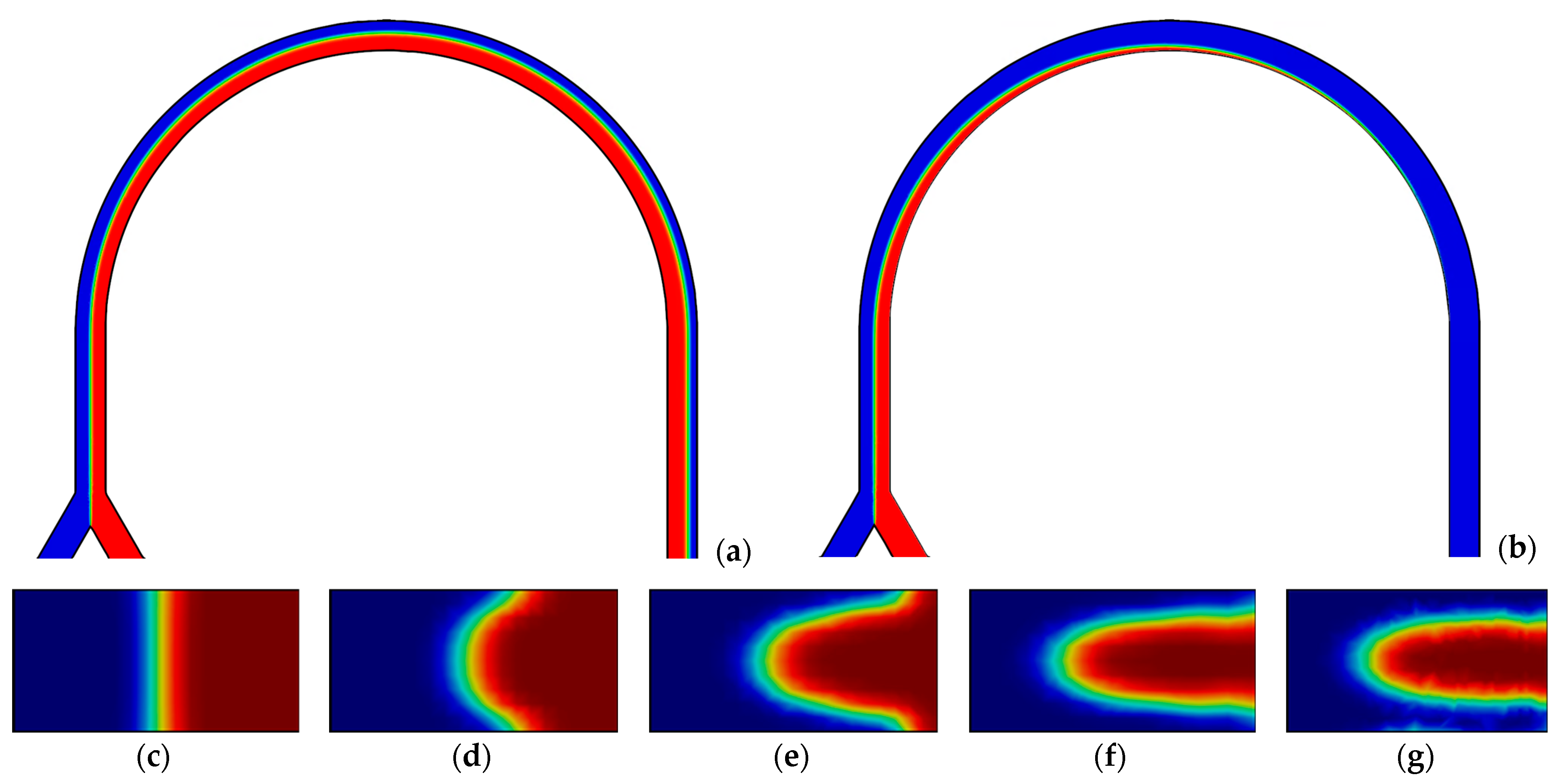
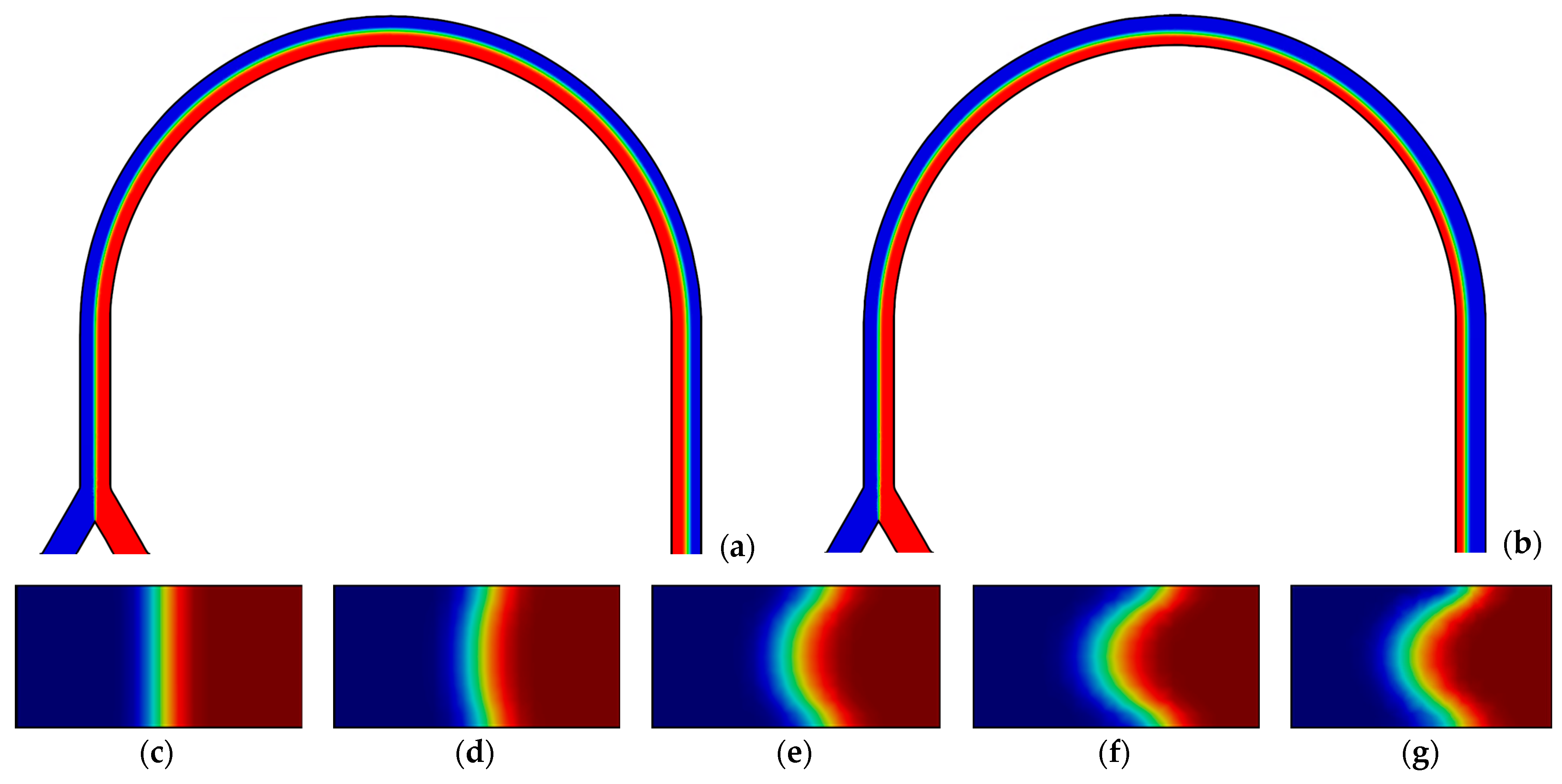
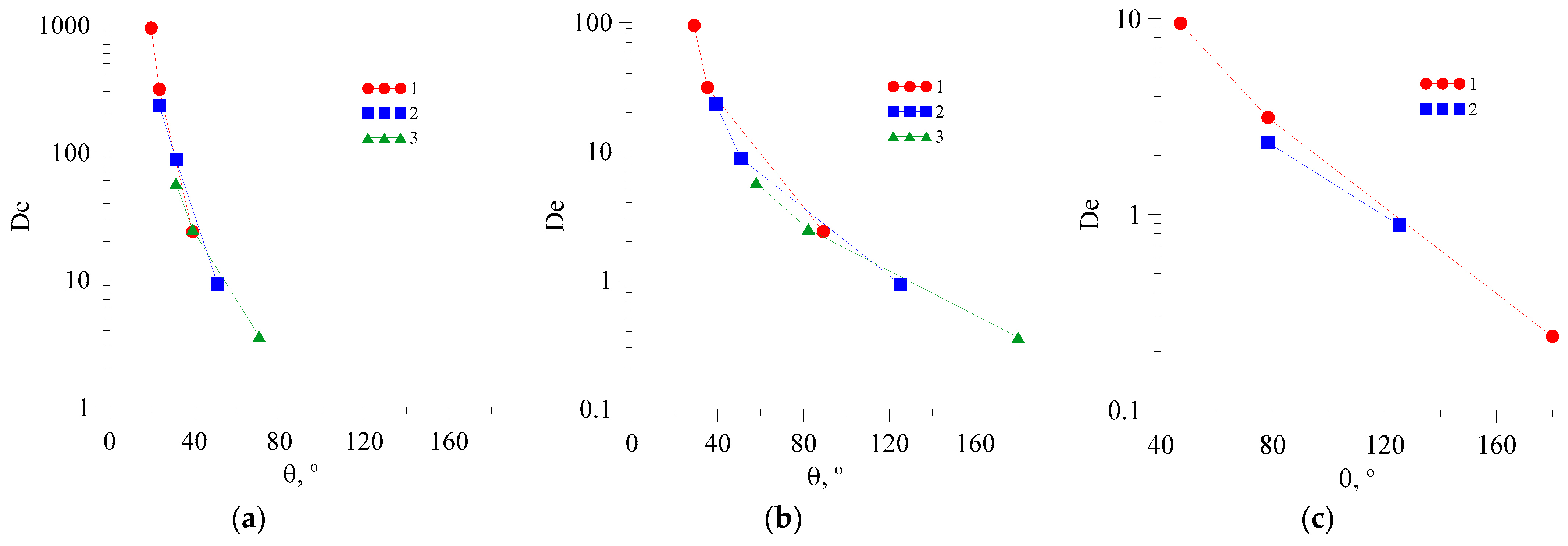
In addition, concentrations were obtained in the longitudinal sections and several cross-sections of the microchannel, and on their basis the values of the flow recirculation angle for each of the cases were derived. For some cases, Figure 5, Figure 6, Figure 7, Figure 8, Figure 9, Figure 10 and Figure 11 show the distributions of the components’ concentration in the longitudinal section of the channel, as well as in several cross-sections of the U-shaped bend at different distances from the beginning of the channel curvature. In these figures, the red colour corresponds to an 100% concentration of one fluid, the blue colour corresponds to an 100% concentration of the other fluid, and the green colour corresponds to their complete mixing. By analyzing these figures, the following conclusions may be drawn: (1) an increase in the consistency index leads to an increase in the value of the flow recirculation angle (Figure 5, Figure 6 and Figure 7); (2) an increase in the flow rate leads to a decrease in the value of the flow recirculation angle (Figure 7, Figure 8 and Figure 9); and (3) an increase in the flow behaviour index leads to an increase in the value of the flow recirculation angle (see Figure 9, Figure 10 and Figure 11). In addition, in some cases, the increase in the value of the recirculation angle of the flow was found to be so great that the U-shaped curvature (180°) was not enough for this recirculation to appear in this micromixer. The same conclusions are drawn from the analysis of the dependence of the value of the recirculation angle of the flow on the flow rate for various values of the coefficients of the power-law model shown in Figure 12. Obviously, for the case of n = 0.8, k = 0.6 Pa·sn, the recirculation mode does not occur at any flow rate, and for the case of n = 0.6, k = 0.6 Pa·sn, it takes place only for a flow rate of 2 mL/min.
To describe the flows in the curved channels and the recycling phenomenon, in addition to the Reynolds number, as mentioned above, the Dean number is used, which is determined via Equation (5). Secondary vortices appear in a curved channel when the Dean number reaches a certain critical value De* [17]. In the literature, one can find a rather wide range of critical values of the Dean number for the curved channels of different shapes: 0.1 < De* < 36. Calculations have shown that in a U-shaped microchannel, the first barely distinguishable Dean vortices appear at a value of De ≈ 0.3.
Similar processes of the emergence and evolution of secondary Dean vortices in non-curved channels with T-shaped junctions have been widely considered in the literature [17,31,32]. Several different flow regimes have been identified, including steady stratified flow, steady symmetric vortex flow, steady asymmetric vortex flow (engulfment), and periodic flow. These depend on the Reynolds number and other parameters.
The low Reynolds numbers are associated with creeping stratified flow, which is characterized by a weak degree of mixing. An increase in the Reynolds number within the mixer results in the formation of a pair of symmetrical horseshoe vortices (Dean vortices), which emerge from the left end wall of the mixer and propagate into the mixing channel. This is what is referred to as a steady symmetric vortex flow regime. In such a case, the flow is symmetrical relative to the central longitudinal plane of the mixer. Each such horseshoe vortex is situated at the interface between the corresponding fluids, and does not cross the boundary between miscible fluids. Consequently, the interface between the two media remains almost flat. Upon reaching the critical value, the flow structure in the mixer undergoes a sudden and significant transformation as the Reynolds number continues to increase. A pair of horseshoe vortices are observed to turn on an angle of 30° in relation to the central longitudinal plane of the mixer as a result of the development of the Taylor–Gertler instability, which is caused by a quarter-turn of each fluid. This is a steady asymmetric vortex flow regime. The rearrangement of the flow within the mixer channel results in the formation of a layered S-shaped structure comprising miscible fluids. The interface of miscible fluids in such a layered structure is highly developed, resulting in a significant enhancement in mixing efficiency. When the flow transitions from the symmetric flow regime to the engulfment flow regime, the mixing efficiency exhibits a significant increase of several tens of times. The initial Dean vortices in a T-mixer emerge at a Dean number of approximately 28.
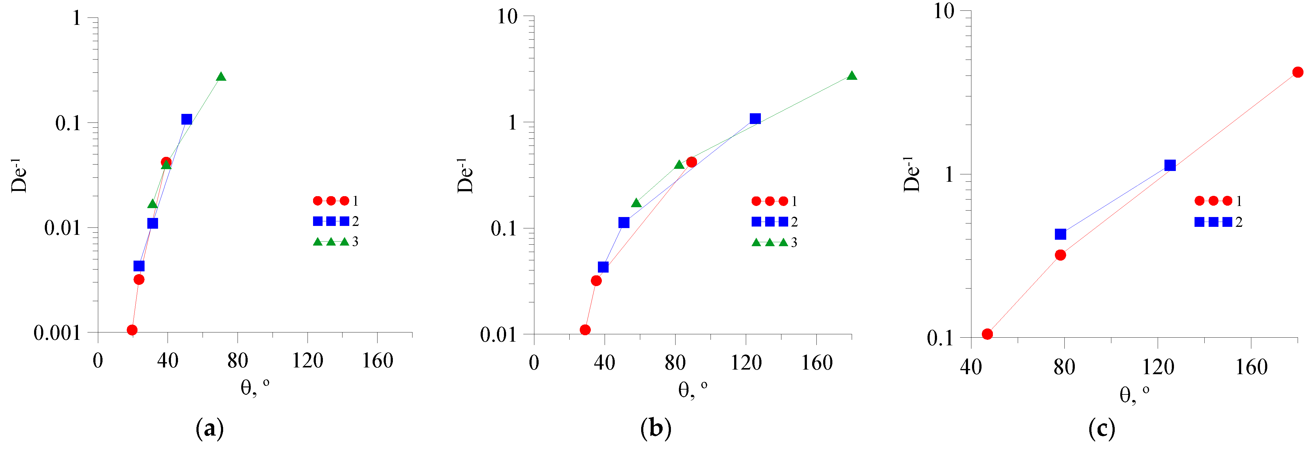
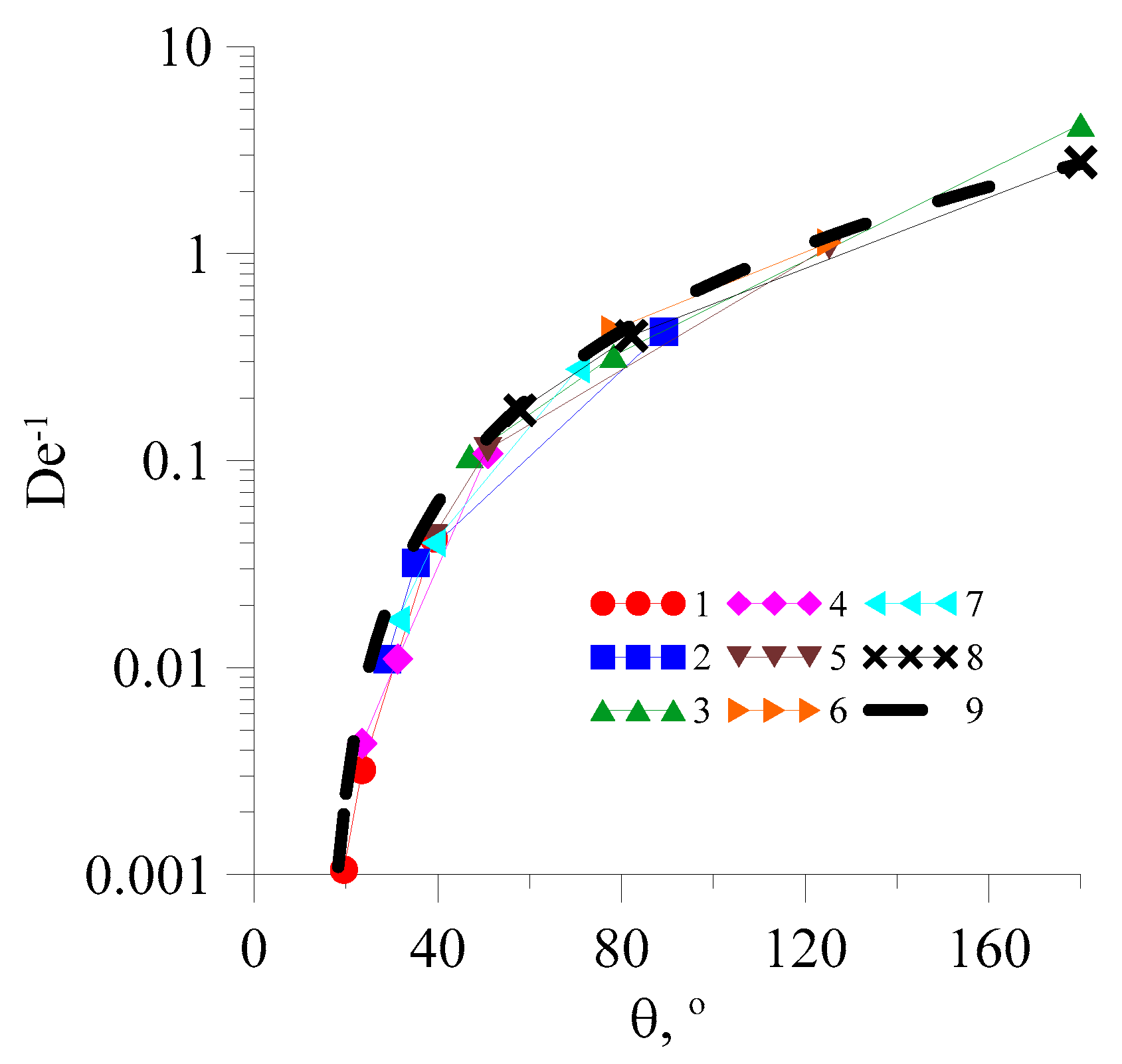
Therefore, Figure 13 illustrates the dependencies of the Dean numbers on the value of the recirculation angle of the flow. It should be noted that the graphs do not include the data points for which the recirculation angle exceeds the limit of 180 degrees. It is evident from this figure that the graphs begin to collapse into one curve. In the referenced work [56], it was noted that the greatest interest lies in the dependence of the inverse Dean number on the value of the recirculation angle, as illustrated in Figure 14. By collecting all these graphs in one figure (Figure 15), one may see that they all fall on one curve, which can be approximated via a correlation of the form:
De 1 θ = a θ c b ,
where a = 10–4, b = 2, and c = 15.
Thus, by substituting (3) into (5) and (5) into (6), one can obtain a system of equations of the form:
1 a θ 1 c b = ρ u 1 2 n d h n k d h 2 R 1 a θ 2 c b = ρ u 2 2 n d h n k d h 2 R .
By solving this system, it is possible to obtain the values of the coefficients of the power-law model n and k, depending on the measured values of the recirculation angle of the flow:
n θ = 2 ln a θ 1 c b a θ 2 c b ln u 1 u 2 k θ = ρ u 1 2 n θ 1 d h n θ 1 a θ 1 c b d h 2 R
The high accuracy of measuring this angle is a key factor, since the functions for n and k are significantly non-linear.
In summary, a methodological approach is hereby proposed for the determination of the properties of non-Newtonian fluids, comprising a series of sequential steps: (1) Pump a non-Newtonian fluid with unknown parameters (n, k) through a micromixer with a flow rate Q1 set equally for both inlets; (2) Determine the recirculation angle θ1; (3) Pump a non-Newtonian fluid with unknown parameters (n, k) through a micromixer with a flow rate Q2 set equally for both inlets; (4) Determine the recirculation angle θ2; (5) Use relations (8) to obtain the parameters of the non-Newtonian fluid (n, k).The flowchart of this sequence is shown in Figure 16.

4. Conclusions

Determining the viscosity of a non-Newtonian fluid is an important and urgent task. In this paper, systematic computational studies of the mixing of two non-Newtonian fluids in a U-shaped microchannel have been carried out. The influence of the flow rate of fluids in the range from 2 mL/min to 20 mL/min, the consistency index in the range from 0.006 Pa·sn to 0.6 Pa·sn, and the flow behaviour index in the range from 0.4 to 0.8 have been studied. As a result, an increase in flow rate was found to lead to a more uniform distribution of velocity across the channel width, as well as to a decrease in the value of the recirculation angle of the flow. An increase in the consistency index has a non-linear effect on the distribution of the velocity modulus. Thus, when it increases from a value of 0.006 Pa·s n to a value of 0.06 Pa·sn, a pronounced central jet is formed at the beginning of the channel to further press against the outer wall, and at k = 0.6 Pa·sn, the velocity distribution is observed to be almost identical to the flow in the non-curved channel. At the same time, an increase in the consistency index increases the value of the recirculation angle of the flow. The influence of the flow behaviour index also affects the distribution of the velocity modulus non-linearly, i.e., its maximum heterogeneity is observed for a value of n = 0.6 to decrease at a value of n = 0.8, and the most uniform distribution is established for n = 0.4. In addition, an increase in the exponent leads to an increase in the value of the recirculation angle of the flow, and in some cases, the latter is so great that the recirculation fails to appear in this micromixer.
Based on the analysis of the obtained data, we have proposed a universal correlation of the following form: De 1 θ = a θ c b , where a = 10−4, b = 2, and c = 15. With its use, it is possible to obtain the values of the coefficients of the power-law model n and k, depending on the measured values of the recirculation angle of the flow. The simplicity of use, speed of measurement and acquisition of results, the requirement of only a small sample size for research, and the ability to integrate the rheometer directly into the flow are all advantages of the method under consideration. In order to determine the consistency index and the flow index, two measurements of the recirculation angles must be conducted at different fluid flow rates (while ensuring that the fluid flow rates at both inlets are equal to each other). The required values are then calculated using the formulas proposed in this article. Rheometers of this type will be in demand in the fields of medicine and oil and gas, among others. In the future, conducting a series of experimental studies on the micromixers manufactured by us in an identical setting and comparing the calculated and experimental data is planned. Thus, the considered micromixer is usable as a viscometer to determine the parameters of a non-Newtonian fluid.

Author Contributions

Conceptualization, A.S.L. and A.V.M.; methodology, A.S.L. and A.V.M.; software, A.S.L. and S.A.F.; validation, A.S.L. and A.V.M.; formal analysis, A.S.L.; investigation, A.S.L. and A.V.M.; resources, A.V.M.; data curation, A.S.L. and A.V.M.; writing—original draft preparation, A.S.L.; writing—review and editing, A.S.L., A.V.M. and S.A.F.; visualization, A.S.L. and S.A.F.; supervision, A.S.L. and A.V.M.; project administration, A.S.L.; funding acquisition, A.V.M. All authors have read and agreed to the published version of the manuscript.

Funding

The research was conducted in fulfilment of the state assignment of the Ministry of Science and Higher Education of the Russian Federation (No. FSRZ-2020-0012).

Data Availability Statement

The raw data supporting the conclusions of this article will be made available by the authors on request.

Conflicts of Interest

The authors declare no conflicts of interest. The funders had no role in the design of the study; in the collection, analyses, or interpretation of data; in the writing of the manuscript; or in the decision to publish the results.

Abbreviations

The following abbreviations are used in this manuscript:
CFDsComputational fluid dynamics
DNSDirect numerical simulation
MEMSMicroelectromechanical systems
NEMSNanoelectromechanical systems
µTASMiniaturized total analysis system
PVTPressure–Volume–Temperature

References

  1. Tabeling, P. Introduction to Microfluidics; Oxford University Press: Oxford, UK, 2005; 301p. [Google Scholar]
  2. Karniadakis, G.; Beskok, A.; Aluru, N. Microflows and Nanoflows: Fundamentals and Simulation; Springer: Berlin/Heidelberg, Germany, 2005; 817p. [Google Scholar]
  3. Karnik, R. Microfluidic mixing. In Encyclopedia of Microfluidics and Nanofluidics; Li, D., Ed.; Springer: Berlin/Heidelberg, Germany, 2008; pp. 1177–1186. [Google Scholar] [CrossRef]
  4. Jeong, G.; Chung, S.; Kim, C.; Lee, S. Applications of micromixing technology. Analyst 2010, 135, 460–473. [Google Scholar] [CrossRef] [PubMed]
  5. Cai, G.; Xue, L.; Zhang, H.; Lin, J.; Jianhan, L. A Review on Micromixers. Micromachines 2017, 8, 274. [Google Scholar] [CrossRef]
  6. Kim, K.-Y.; Ansari, M.A.; Afzal, A. Passive Micromixers. Micromachines 2018, 174, 250. [Google Scholar] [CrossRef]
  7. Stroock, A.D.; Dertinger, S.K.; Whitesides, G.M.; Ajdari, A. Patterning flows using grooved surfaces. Anal. Chem. 2002, 74, 5306–5312. [Google Scholar] [CrossRef] [PubMed]
  8. Vanka, S.P.; Luo, G.; Winkler, C.M. Numerical study of scalar mixing in curved channels at low Reynolds number. AIChE J. 2004, 50, 2359–2368. [Google Scholar] [CrossRef]
  9. Aubin, J.; Fletcher, D.F.; Xuereb, C. Design of micromixers using CFD modeling. Chem. Eng. Sci. 2005, 60, 2503–2516. [Google Scholar] [CrossRef]
  10. Lin, Y.C.; Chung, Y.C.; Wu, C.Y. Mixing enhancement of the passive microfluidic mixer with J-shaped baffles in the tee channel. Biomed. Microdev. 2007, 9, 215–221. [Google Scholar] [CrossRef]
  11. Hoffmann, M.; Schluter, M.; Rubiger, N. Experimental investigation of liquid–liquid mixing in T-shaped micro-mixers using µ-LIF and µ-PIV. Chem. Eng. Sci. 2006, 61, 2968–2976. [Google Scholar] [CrossRef]
  12. Mansur, E.A.; Mingxing, Y.E.; Yundong, W.; Youyuan, D. A state-of-the-art review of mixing in microfluidic mixers. CIESC J. 2008, 16, 503–516. [Google Scholar] [CrossRef]
  13. Bokenkamp, D.; Desai, A.; Yang, X. Microfabricated silicon mixers for submillisecond quench-flow analysis. Anal. Chem. 1998, 70, 232–236. [Google Scholar] [CrossRef]
  14. Gobby, D.P.; Angeli, A. Mixing characteristics of T-type microfluidic mixers. J. Micromech. Microeng. 2001, 11, 126–132. [Google Scholar] [CrossRef]
  15. Engler, M.; Kockmann, N.; Kiefer, T.; Woias, P. Numerical and experimental investigations on liquid mixing in static micromixers. Chem. Eng. J. 2004, 101, 315–322. [Google Scholar] [CrossRef]
  16. Telib, H.; Manhart, M.; Iollo, A. Analysis and low-order modeling of the inhomogeneous transitional flow inside a T-mixer. Phys. Fluids 2004, 16, 2717–2731. [Google Scholar] [CrossRef]
  17. Lobasov, A.S. Features of the Flow and Mixing Modes of Fluids in a T-Shaped Microchannel. Ph.D. Thesis, Tomsk State University, Tomsk, Russia, 19 December 2018. [Google Scholar]
  18. Galletti, C.; Brunazzi, E.; Mauri, R. Unsteady mixing of binary liquid mixtures with composition-dependent viscosity. Chem. Eng. J. 2017, 164, 333–343. [Google Scholar] [CrossRef]
  19. Soleymani, A.; Kolehmainen, E.; Turunen, I. Numerical and experimental investigations of liquid mixing in T-type micromixers. Chem. Eng. J. 2007, 135, 219–228. [Google Scholar] [CrossRef]
  20. Fani, A.; Camarri, S.; Salvetti, M.V. Unsteady asymmetric engulfment regime in a T-mixer. Phys. Fluids 2014, 26, 074101-1–074101-18. [Google Scholar] [CrossRef]
  21. Rudyak, V.Y.; Minakov, A.V.; Gavrilov, A.A.; Dekterev, A.A. Modeling of flows in micromixers. Thermophys. Aeromech. 2010, 17, 565–576. [Google Scholar] [CrossRef]
  22. Minakov, A.V.; Rudyak, V.Y.; Gavrilov, A.A.; Dekterev, A.A. On optimization of mixing process of liquids in microchannels. J. SFU Math. Phys. Series 2010, 3, 146–156. [Google Scholar]
  23. Minakov, A.V.; Rudyak, V.Y.; Gavrilov, A.A.; Dekterev, A.A. Mixing in a T-shaped micromixer at moderate Reynolds numbers. Thermophys. Aeromech. 2012, 19, 385–395. [Google Scholar] [CrossRef]
  24. Minakov, A.V.; Lobasov, A.S.; Dekterev, A.A. Simulation of hydrodynamics and convective heat transfer in microchannels. Comp. Cont. Mech. 2012, 5, 481–488. [Google Scholar] [CrossRef]
  25. Lobasov, A.S.; Minakov, A.V. Numerical simulation of heat and mass transfer processes in microchannels using CFD-package σFlow. Comp. Res. Mod. 2012, 4, 781–792. [Google Scholar] [CrossRef]
  26. Minakov, A.V.; Yagodnicyna, A.A.; Lobasov, A.S.; Rudyak, V.Y.; Bilsky, A.V. Experiment Calculated Investigation of fluids Mixing in T-Channel. Nano Microsys. Technol 2013, 3, 18–21. [Google Scholar]
  27. Minakov, A.V.; Rudyak, V.Y.; Dekterev, A.A.; Gavrilov, A.A. Investigation of slip boundary conditions in the T-shaped microchannel. Int. J. Heat Fluid Flow 2013, 43, 161–169. [Google Scholar] [CrossRef]
  28. Rudyak, V.Y.; Minakov, A.V. Modeling and optimization of Y-type micromixers. Micromachines 2014, 5, 886–912. [Google Scholar] [CrossRef]
  29. Lobasov, A.S.; Minakov, A.V.; Rudyak, V.Y. Study of the Mixing Regimes of a Fluid and a Nanofluid in a T-shaped Micromixer. J. Eng. Phys. Thermophys. 2018, 91, 124–135. [Google Scholar] [CrossRef]
  30. Lobasov, A.S.; Minakov, A.V.; Rudyak, V.Y. Flow Modes of Non-Newtonian Fluids with Power-Law Rheology in a T-Shaped Micromixer. Theor. Found. Chem. Technol. 2018, 52, 393–403. [Google Scholar] [CrossRef]
  31. Lobasov, A.S.; Minakov, A.V. Analyzing mixing quality in a T-shaped micromixer for different fluids properties through numerical simulation. Chem. Eng. Proc. Proc. Intens. 2018, 124, 11–23. [Google Scholar] [CrossRef]
  32. Lobasov, A.S.; Minakov, A.V.; Kuznetsov, V.V.; Rudyak, V.Y.; Shebeleva, A.A. Investigation of mixing efficiency and pressure drop in T-shaped micromixers. Chem. Eng. Proc. Proc. Intens. 2018, 134, 105–114. [Google Scholar] [CrossRef]
  33. Minakov, A.V.; Lobasov, A.S.; Shebeleva, A.A.; Shebelev, A.V. Analysis of hydraulic mixing efficiency in widespread models of micromixers. Fluids 2020, 5, 211. [Google Scholar] [CrossRef]
  34. Rudyak, V.Y.; Aniskin, V.M.; Kuznetsov, V.V.; Maslov, A.A.; Minakov, A.V.; Mironov, S.G. Modeling of Micro and Nanoflows; SIBSTRIN: Novosibirsk, Russia, 2014. [Google Scholar]
  35. Rudyak, V.Y.; Minakov, A.V. Modern Problems of Micro and Nanofluidics; Nauka: Novosibirsk, Russia, 2016. [Google Scholar]
  36. Rudyak, V.Y.; Aniskin, V.M.; Maslov, A.A.; Minakov, A.V.; Mironov, S.G. Micro and Nanoflows. Modeling and Experiments; Springer: Berlin/Heidelberg, Germany, 2018; 241p. [Google Scholar] [CrossRef]
  37. Manz, A.; Graber, N.; Widmer, H.M. Miniaturized total chemical analysis systems: A novel concept for chemical sensing. Sens. Actuat. B Chem. 1990, 1, 244–248. [Google Scholar] [CrossRef]
  38. Elvira, K.S.; i Solvas, X.C.; Wootton, R.C.R.; de Mello, A.J. The past, present and potential for microfluidic reactor technology in chemical synthesis. Nat. Chem. 2013, 5, 905–915. [Google Scholar] [CrossRef]
  39. Yew, M.; Ren, Y.; Koh, K.S.; Sun, C.; Snape, C. A Review of state-of-the-art microfluidic technologies for environmental applications: Detection and remediation. Glob. Chall. 2018, 3, 1800060. [Google Scholar] [CrossRef]
  40. Convery, N.; Gadegaard, N. 30 years of microfluidics. Micro Nano Eng. 2019, 2, 76–91. [Google Scholar] [CrossRef]
  41. Wu, W.-T.; Massoudi, M. Recent Advances in Mechanics of Non-Newtonian Fluids. Fluids 2020, 5, 10. [Google Scholar] [CrossRef]
  42. Leusheva, E.; Brovkina, N.; Morenov, V. Investigation of Non-Linear Rheological Characteristics of Barite-Free Drilling Fluids. Fluids 2021, 6, 327. [Google Scholar] [CrossRef]
  43. Pantokratoras, A. A Note on the Drag Coefficient of Steady Flow of Non-Newtonian, Power-Law Fluids across Unbounded Two-Dimensional Bodies at Low Reynolds Numbers. Fluids 2017, 2, 5. [Google Scholar] [CrossRef]
  44. Nimura, T.; Tsukahara, T. Viscoelasticity-Induced Instability in Plane Couette Flow at Very Low Reynolds Number. Fluids 2022, 7, 241. [Google Scholar] [CrossRef]
  45. Jeyaraj, J.A.; Perez, A.; Zayed, A.; Mullins, A.G.; Tejada-Martinez, A.E. Computational Fluid Dynamics Modeling of Concrete Flows in Drilled Shafts. Fluids 2024, 9, 13. [Google Scholar] [CrossRef]
  46. Jirout, T.; Krupica, A.; Kolomijec, A. CFD Analysis of Ultra-High-Performance Concrete Rheological Tests. Fluids 2024, 9, 45. [Google Scholar] [CrossRef]
  47. Yu, G.; Yu, B.; Liang, Y.; Wang, M.; Joshi, Y.; Sun, D. A new general model for phase-change heat transfer of waxy crude oil during the ambient-induced cooling process. Numer. Heat Transfer. Part A Appl. 2017, 71, 511–527. [Google Scholar] [CrossRef]
  48. Toshimitsu, M.; Yonemoto, Y.; Kawahara, A. Pressure Change for Single- and Two-Phase Non-Newtonian Flows through Sudden Contraction in Rectangular Microchannel. Fluids 2021, 6, 440. [Google Scholar] [CrossRef]
  49. Rubio Martínez, A.; Chávez Castellanos, A.E.; Noguez Méndez, N.A.; Aragón Rivera, F.; Pliego Díaz, M.; Sigalotti, L.D.G.; Vargas, C.A. Flow Modeling of a Non-Newtonian Viscous Fluid in Elastic-Wall Microchannels. Fluids 2024, 9, 77. [Google Scholar] [CrossRef]
  50. Raihan, M.K.; Jagdale, P.P.; Wu, S.; Shao, X.; Bostwick, J.B.; Pan, X.; Xuan, X. Flow of Non-Newtonian Fluids in a Single-Cavity Microchannel. Micromachines 2021, 12, 836. [Google Scholar] [CrossRef] [PubMed]
  51. Mahammedi, A.; Tayeb, N.T.; Kim, K.-Y.; Hossain, S. Mixing Enhancement of Non-Newtonian Shear-Thinning Fluid for a Kenics Micromixer. Micromachines 2021, 12, 1494. [Google Scholar] [CrossRef]
  52. Bayareh, M.; Jafari Ghahfarokhi, N. Micromixing of Non-Newtonian Fluids in a Passive Micromixer with an Inner Eccentric Cylindrical Obstacle. Iran. J. Chem. Chem. Eng. 2024, 43, 3350–3356. [Google Scholar] [CrossRef]
  53. Carravetta, A.; Fecarotta, O.; Martino, R.; Morani, M.C. Rheological Characterization of Non-Newtonian Mixtures by Pressure Pipe Tests. Fluids 2021, 6, 419. [Google Scholar] [CrossRef]
  54. Magnon, E.; Cayeux, E. Precise Method to Estimate the Herschel-Bulkley Parameters from Pipe Rheometer Measurements. Fluids 2021, 6, 157. [Google Scholar] [CrossRef]
  55. Cayeux, E. Calibration of Thixotropic and Viscoelastic Shear-Thinning Fluids Using Pipe Rheometer Measurements. Fluids 2024, 9, 23. [Google Scholar] [CrossRef]
  56. Pryazhnikov, M.I.; Yakimov, A.S.; Denisov, I.A.; Pryazhnikov, A.I.; Minakov, A.V.; Belobrov, P.I. Fluid Viscosity Measurement by Means of Secondary Flow in a Curved Channel. Micromachines 2022, 13, 1452. [Google Scholar] [CrossRef]
  57. Gavrilov, A.A.; Minakov, A.V.; Dekterev, A.A.; Rudyak, V.Y. A numerical algorithm for modeling laminar flows in an annular channel with eccentricity. J. App. Ind. Math. 2011, 5, 559. [Google Scholar] [CrossRef]
  58. Gavrilov, A.A.; Minakov, A.V.; Dekterev, A.A.; Rudyak, V.Y. Numerical algorithm for fully developed laminar flow of a non-Newtonian fluid through an eccentric annulus. Comput. Technol 2012, 17, 44–56. [Google Scholar]
  59. Patankar, S. Numerical Heat Transfer and Fluid Flow; CRC Press: Boca Raton, FL, USA, 1980. [Google Scholar] [CrossRef]
  60. Bystrov, Y.A.; Isaev, S.A.; Kudryavtsev, N.A.; Leontiev, A.I. Numerical Modeling of Vortex Intensification of Heat Transfer in Tube Bundle; Sudostroienie: St. Petersburg, Russia, 2005. [Google Scholar]
  61. Ferziger, J.H.; Peric, M. Computational Methods for Fluid Dynamics; Springer: Berlin/Heidelberg, Germany, 2002; 423p. [Google Scholar]
  62. Leonard, B.P. A stable and accurate convective modeling procedure based on quadratic upstream interpolation. Comp. Math. Appl. Mech. Eng. 1979, 19, 59. [Google Scholar] [CrossRef]
  63. Rhie, C.M.; Chow, W.L. Numerical study of the turbulent flow past an airfoil with trailing edge separation. AIAA J. 1983, 21, 1525. [Google Scholar] [CrossRef]
  64. Trottenberg, U.; Oosterlee, C.W.; Schüller, A. Multigrid; Academic Press Inc.: San Diego, CA, USA, 2001; 631p. [Google Scholar]
Figure 1. Numerical grid and problem geometry. The direction of flow is indicated by the circle arrow, while the direction of the view is indicated by the straight arrows.
Fluids 10 00065 g001
Figure 2. Distribution of the velocity modulus in the longitudinal section of the channel at Q: (a) 2 mL/min (Re = 132.4; De = 23.8); (b) 10 mL/min (Re = 1738.3; De = 312.9); and (c) 20 mL/min (Re = 5296.5; De = 948.4). k = 0.006 Pa·sn, n = 0.4.
Fluids 10 00065 g002
Figure 3. Distribution of the velocity modulus in the longitudinal section of the channel at n: (a) 0.6 (Re = 1294.3; De = 233); (b) 0.8 (Re = 317.9; De = 57.2). Q = 20 mL/min, k = 0.006 Pa·sn.
Fluids 10 00065 g003
Figure 4. Distribution of the velocity modulus in the longitudinal section of the channel at k: (a) 0.06 Pa·sn (Re = 527; De = 94.8); (b) 0.6 Pa·sn (Re = 52.7; De = 9.5). Q = 20 mL/min, n = 0.4.
Fluids 10 00065 g004
Figure 5. Concentration distribution in the longitudinal section of the channel: (a) central; (b) on the wall. Cross-sections of the channel located at an angle: (c) 0°; (d) 45°; (e) 90°; (f) 135°; and (g) 180°. Q = 2 mL/min, k = 0.006 Pa·sn, n = 0.4 (Re = 132.4; De = 23.8).
Fluids 10 00065 g005
Figure 6. Concentration distribution in the longitudinal section of the channel: (a) central; (b) on the wall. Cross-sections of the channel located at an angle: (c) 0°; (d) 45°; (e) 90°; (f) 135°; and (g) 180°. Q = 2 mL/min, k = 0.06 Pa·sn, n = 0.4 (Re = 13.2; De = 2.4).
Fluids 10 00065 g006
Figure 7. Distribution of concentrations in the longitudinal section of the channel: (a) central; (b) on the wall. Cross-sections of the channel located at an angle: (c) 0°; (d) 45°; (e) 90°; (f) 135°; and (g) 180°. Q = 2 mL/min, k = 0.6 Pa·sn, n = 0.4 (Re = 1.3; De = 0.2).
Fluids 10 00065 g007
Figure 8. Concentration distribution in the longitudinal section of the channel: (a) central; (b) on the wall. Cross-sections of the channel located at an angle: (c) 0°; (d) 45°; (e) 90°; (f) 135°; and (g) 180°. Q = 10 mL/min, k = 0.6 Pa·sn, n = 0.4 (Re = 17.4; De = 3.1).
Fluids 10 00065 g008
Figure 9. Concentration distribution in the longitudinal section of the channel: (a) central; (b) on the wall. Cross-sections of the channel located at an angle: (c) 0°; (d) 45°; (e) 90°; (f) 135°; and (g) 180°. Q = 20 mL/min, k = 0.6 Pa·sn, n = 0.4 (Re = 52.7; De = 9.5).
Fluids 10 00065 g009
Figure 10. Concentration distribution in the longitudinal section of the channel: (a) central; (b) on the wall. Cross-sections of the channel located at an angle: (c) 0°; (d) 45°; (e) 90°; (f) 135°; and (g) 180°. Q = 20 mL/min, k = 0.6 Pa·sn, n = 0.6 (Re = 12.9; De = 2.3).
Fluids 10 00065 g010
Figure 11. Concentration distribution in the longitudinal section of the channel: (a) central; (b) on the wall. Cross-sections of the channel located at an angle: (c) 0°; (d) 45°; (e) 90°; (f) 135°; and (g) 180°. Q = 20 mL/min, k = 0.6 Pa·sn, n = 0.8 (Re = 3.2; De = 0.6).
Fluids 10 00065 g011
Figure 12. Dependence of the value of the recirculation angle of the flow on the fluid flow rate: (a) k = 0.006 Pa·sn; (b) 2—k = 0.06 Pa·sn; and (c) k = 0.6 Pa·sn. 1—n = 0.4, 2—n = 0.6, 3—n = 0.8.
Fluids 10 00065 g012
Figure 13. Dependence of the Dean number on the value of the recirculation angle of the flow: (a) k = 0.006 Pa·sn; (b) 2—k = 0.06 Pa·sn; and (c) k = 0.6 Pa·sn. 1—n = 0.4, 2—n = 0.6, 3—n = 0.8.
Fluids 10 00065 g013
Figure 14. Dependence of the inverse Dean number on the value of recirculation angle of the flow: (a) k = 0.006 Pa·sn; (b) 2—k = 0.06 Pa·sn; and (c) k = 0.6 Pa·sn. 1—n = 0.4, 2—n = 0.6, 3—n = 0.8.
Fluids 10 00065 g014
Figure 15. Dependence of the inverse Dean number on the value of the recirculation angle of the flow: 1—n = 0.4, k = 0.006 Pa·sn; 2—n = 0.4, k = 0.06 Pa·sn; 3—n = 0.4, k = 0.6 Pa·sn; 4—n = 0.6, k = 0.006 Pa·sn; 5—n = 0.6, k = 0.06 Pa·sn; 6—n = 0.6, k = 0.6 Pa·sn; 7—n = 0.8, k = 0.006 Pa·sn; 8—n = 0.8, k = 0.06 Pa·sn; and 9—correlation (6).
Fluids 10 00065 g015
Figure 16. The step-by-step flowchart of the proposed methodology.
Fluids 10 00065 g016
Disclaimer/Publisher’s Note: The statements, opinions and data contained in all publications are solely those of the individual author(s) and contributor(s) and not of MDPI and/or the editor(s). MDPI and/or the editor(s) disclaim responsibility for any injury to people or property resulting from any ideas, methods, instructions or products referred to in the content.