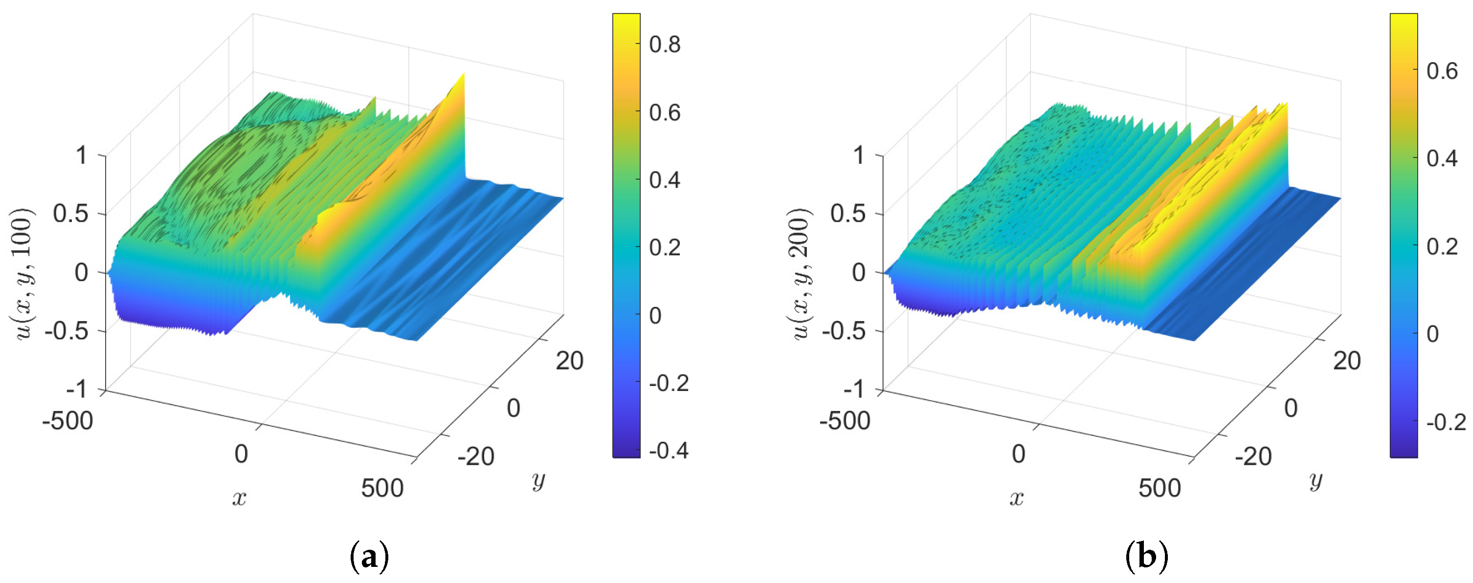
Abstract
In a recent paper, denoted by MG24 in this text, we used a modified Korteweg–de Vries (KdV) equation to describe the evolution of wind-driven water wave packets in shallow water. The modifications were several forcing/friction terms describing wave growth due to critical-level instability in the air, wave decay due to laminar friction in the water at the air–water interface, wave growth due to turbulent wave stress in the air near the interface, and wave decay due to a turbulent bottom boundary layer. The outcome was a KdV–Burgers type of equation that can be a stable or unstable model depending on the forcing/friction parameters. In most cases that we examined, many solitary waves are generated, suggesting the formation of a soliton gas. In this paper, we extend that model in the horizontal direction transverse to the wind forcing to produce a similarly modified Kadomtsev–Petviashvili equation (KPII for water waves in the absence of surface tension). A modulation theory is described for the cnoidal and solitary wave solutions of the unforced KP equation, focusing on the forcing/friction terms and the transverse dependence. Then, using similar initial conditions to those used in MG24, that is a sinusoidal wave with a slowly varying envelope, but supplemented here with a transverse sinusoidal term, we find through numerical simulations that the radiation field upstream is enhanced, but that a soliton gas still emerges downstream as in MG24.
1. Introduction
The Korteweg–de Vries (KdV) equation is widely used to model surface waves in shallow water. However, there has been surprisingly little interest in using it to study wind-generated waves. Recent notable exceptions are the examination of ocean data by Costa et al. [1], and the works by Zdyrski and Feddersen [2], Manna and Latifi [3] using an unstable KdV–Burgers equation, that is, a KdV equation with a wind-forcing term. Recently, we used a similar approach in Maleewong and Grimshaw [4] (hereafter referred to as MG24). We derived and analysed a KdV equation modified with several forcing/friction terms. These represented the critical-level instability theory of Miles [5] for the growth of wind waves; a forcing term modelling turbulent wave stress in the air at the water surface; and two frictional terms, a laminar boundary layer at the water surface and a model of turbulent bottom stress. For wind waves, a major feature of the KdV equation is that it is uni-directional, and a widely used extension is the Kadomtsev–Petviashvili equation (KPII for water waves in the absence of surface tension), which accounts for weak spatial dependence in the transverse direction. Hence, here we extend our derived KdV–Burgers equation to a KP–Burgers equation, containing the same forcing/friction terms.
Like the KdV equation, the KP equation is integrable with multi-soliton solutions and many fascinating soliton interactions, sometimes called web-solutions; see Biondini and Pelinovsky [6], Chakravarty and Kodama [7], and the many papers by these latter authors and their colleagues. However, these are not directly our concern here; instead, our purpose is to examine how the soliton gas solutions found in MG24 behave under transverse perturbation using our KP–Burgers extension of the KdV–Burgers equation. We note that the KdV solitary wave is stable in the KPII framework.
In Section 2, we present the KP–Burgers equation with forcing/friction modifications as developed in MG24. Then, in Section 3 we describe wave propagation, using an analogous approach to that in MG24. In Section 3.1, we present the well-known cnoidal wave and solitary wave solutions of KPII. Then, in Section 3.2 we present the Whitham modulation theory, using the conservation laws for mass and energy together with that for conservation of waves. In Section 3.3, we describe a modulated solitary wave train. Then, in Section 4 we present some numerical simulations of the KP–Burgers equation, and compare the outcomes with the modulation theory. The numerical scheme is described in the Appendix A. We conclude with a summary and discussion in Section 5.
2. KP–Burgers Equation
The KP–Burgers (KPB) equation is obtained by adding a weak y-dependence to the KdV–Burgers (KdVB) equation of MG24. The outcome is expressed here in the same non-dimensional variables as in MG24.
The left-hand side on its own is the well-known KPII equation, and like its KdV counterpart is expressed in a reference frame moving in the positive x-direction with the linear long-wave speed. The full linear dispersion relation for water waves expressed in dimensional variables is, in the absence of surface tension, in water of depth h, with wavenumbers k and l in the x- and y-directions, and . To obtain the KdV and KP limits, this is expanded around for small k and l, yielding . Reverting to time and space variables yields the linear terms on the left-hand side of Equation (1), expressed here in the scaled, non-dimensional time and space variables . The nonlinear term is found by a well-known asymptotic amplitude expansion, and u is a non-dimensional scaled wave amplitude. The spatial domain is , , with zero boundary conditions at infinity. In the numerical simulations, these domains are replaced by and , with periodic boundary conditions and with frictional sponge layers added near the boundaries, analogous to that used in MG24 for the KdVB equation.
The forcing/friction term on the right-hand side of Equation (1) is the same as in MG24. Summarising briefly, as above, is the dimensional linear long-wave speed, h is the undisturbed depth, are the air/water densities, respectively, is the kinematic viscosity, is a wind surface drag coefficient, is a bottom drag coefficient, is a typical wave amplitude, is a reference wind velocity introduced by Miles [5], is a scaling velocity for the surface wave stress in the air, and K and are numerical factors introduced to make the non-dimensional scaling suitable for shallow-water waves of small amplitude. The first term in has two parts: the first part is due to the critical-level instability of Miles [5], and the second part describes damping due to a laminar frictional boundary layer at the water surface. The second term describes a nonlinear instability due to turbulent wave stress in the air at the interface. The third term is a decay term modelling turbulent bottom stress.
The initial condition is a sinusoidal function designed to produce a wave packet, with many solitary waves, resembling a soliton gas as found in the KdVB simulations of MG24. The initial conditions reported here are as follows:
is the initial wave amplitude, and are the initial wavenumbers. Both cases (A) and (B) are symmetric in y, and have zero mean in the x- and y-directions. Case (B), with , is a small y-dependent perturbation to the x-dependent initial condition of MG24. In the numerical simulations, which are on a periodic domain , the initial condition is combined with envelopes and with long length scales such that and . We usually set , as in MG24, corresponding in dimensional coordinates to a 5-second wave in water of depth , while varies in the range . is chosen so that at ; see Section 4. In most cases, is omitted; that is, we set and apply periodic boundary conditions at .
The expression for v in terms of u is best given by the symmetric integral Ablowitz and Villarroel [8]:
M is the mass along the x-direction and in general depends on . But here Equation (1), like the unforced KP equation, has a mass constraint, , obtained by letting in Equation (1). This in turn implies that is independent of y for . Further, the boundary conditions as then show that . Although the initial condition Equation (4) may not satisfy this constraint, ref. Molinet et al. [9] showed that nevertheless the solution of Equation (1) satisfies the constraint in all . Physically, the mass travels to infinity in the y-direction infinitely fast at . When the boundary conditions at infinity are replaced by periodic boundary conditions, , and again is independent of y for , and imposing the condition that yields . But if instead it is only required that u is periodic in , then can vary with t. The global mass is and is likewise zero for , except for purely periodic boundary conditions at .
The KPB Equation (1) has an energy conservation law:
Hence, we define an energy along the x-direction,
and then obtain the energy law:
The global energy is and is conserved when there is no forcing/friction term, ; otherwise it grows or decays depending on the sign of the domain integral of .
The KPB equation (1) can be reduced to a KdVB equation by seeking solutions which depend only on the time t and the slanted coordinate X:
is the slope relative to the x-axis and is a constant in this reduction. Hence, the modulated solitary and cnoidal waves in the KdV–Burgers equation of MG24 are solutions here in the slanted coordinate X.
3. Wave Propagation
3.1. Cnoidal Waves
In the absence of the forcing/friction terms, the KP–Burgers Equation (1) reduces to the KP equation when it has well-known periodic and solitary wave solutions, the same as in the KdV equation, but propagation at an angle to the x-axis; see Biondini and Pelinovsky [6], Osborne [10], Ablowitz et al. [11], Grava et al. [12], Ryskamp et al. [13] for comprehensive accounts and modulation theory. Here, our concern, as in MG24, is the effect of the forcing/friction term on the wave evolution. Hence, we use the Whitham modulation approach of averaging conservation laws, noting that Osborne [10], Ablowitz et al. [11], Grava et al. [12], Ryskamp et al. [13] exploited the integrability of the unforced KP equation in various ways, a technique not available here due to the forcing/friction term.
As is customary in modulation theory, we assume that the wave parameters, amplitude, wavenumbers, etc., vary slowly with ; formally, a small parameter should be used to define this slow variation but it is not explicitly used here, although we note that it would not be connected to the small parameters implicitly used in the derivation of the KPB Equation (1). First, we define a phase with wavenumbers and frequency , where
where is the phase speed in the direction normal to the wave front, and is the slope of the wave front. The equations for conservation of waves come from eliminating from Equation (11):
The modulation equation for S is
Equation (13) is formally independent of the magnitudes of k and l but depends on the other wave parameters which are contained in V.
The remaining modulation theory parallels that in MG24 for the KdVB equation, but is briefly summarised here for convenience. Thus, we seek a modulated wave of the form which is periodic in with period and where the dependence on is slowly varying and expressed through the wave parameters. We define a wave average by
The wave is then decomposed into a periodic wave with zero mean, and a mean level D:
We recall that the explicit dependence in is slowly varying. Correspondingly, is decomposed into a periodic wave with zero mean and a mean level :
From the energy Equation (9), we define the wave energy by
which is a slowly varying function of .
On extracting the fast dependence on , the KPB Equation (1) reduces at leading order in the implicit slow variation to
The same outcome comes from the KdV equation (10), with expressed in terms of the slanted coordinate , with no other fast y-dependence; the slope in Equation (10) is now replaced with S. That is, and then , . In effect, if is replaced by V, then Equation (18) is the same equation as that used in MG24 to describe the modulated cnoidal wave. Hence, here this is given by
At leading order, the corresponding expression for is found from Equation (16), . In Equations (19) and (20), is the Jacobi elliptic function of modulus m () and are the complete elliptic integrals of the first and second kinds, respectively. The cnoidal wave Equation (19) is periodic in with a period , which defines . The wave energy is given by
The expression is used here as in Grimshaw and Yuan [14] and in MG24, and depends only on the modulus m.
When the modulus , , , and the cnoidal wave Equation (19) collapses to a linear sinusoidal wave:
On the other hand, when the modulus , , and . The cnoidal wave Equation (19) becomes a solitary wave train, defined on a periodic lattice, and riding on a background level D.
In this limit, but and stay finite. but remains finite and is given by
3.2. Modulated Waves
The cnoidal wave parameters are slowly varying functions of and are reduced to four by the relations in Equation (20). Similarly to MG24’s equations, describing their evolution are the two wave conservation equations (12) and two equations describing the conservation of mass and energy.
The conservation of mass equation is found from the wave average of Equation (1) and yields an equation for the mean level D:
The slowly varying terms (on the left-hand side) and , (on the right-hand side) have been omitted because they are much smaller than the retained terms due to the slow variations in . The effect of the bottom stress term with coefficient is expected to cause as , most clearly evident when D and E depend only on t. The final modulation equation is found by taking the wave average of the conservation of energy, Equation (9), expressed here in terms of and D, with eliminated using Equation (25):
Note that E depends only on A and m. Next, using the cnoidal wave Equation (19) the x and y fluxes are given by
when , , and , corresponding to a linear frequency of and hence a group velocity with components and , in the x- and y-directions, respectively.
On the other hand, when , . Since , the mean-level Equation (25) reduces to an equation for alone and yields a solution independently of the other modulation parameters. Hence, D can be regarded as known in this limit. In order to simplify the subsequent analysis of a modulated solitary wave train, we set in the following analysis unless stated otherwise. As in Grimshaw and Yuan [14], in the limit it is necessary to take account of terms proportional to , where , noting that , and stays finite. The outcome is found after replacing E with in Equation (26):
As in MG24, is the solitary wave train limit of . The last term on the right-hand side of Equation (30), proportional to , is unexpected. Although in this limit, and S may remain finite.
3.3. Solitary Wave Train
For a solitary wave train, the modulation equations are Equations (13) and (30), combined with an equation for the wavenumber l if needed. If there is no -dependence, then are constants and solutions can be found which depend on t only. These are described in MG24 and represent wave growth for the terms in and wave decay for the terms in .
In order to examine the effect of y-dependence in the system of Equations (13) and (30), we seek solutions S and , which depend only on . Since with this assumption k is a constant, , and the system becomes
The system has a symmetry, , and so henceforth in the remainder of this subsection we assume that . In terms of Riemann invariants, the system becomes
We note that and , and so and propagate in the positive and negative y-directions, respectively. In the absence of the forcing/friction term on the right-hand side, we may set , leaving a solvable Hopf equation for , describing propagation in with speed , which can then be expressed as a function of .
Since Equations (13), (30) and (33) for seem not to be exactly integrable, we examine two limiting cases. First, suppose that , when . Then, suitable Riemann invariants are , . In the reduction, and . As S increases, increases, and consequently increases. Secondly, suppose that when . Then, suitable Riemann invariants are . In the reduction, , . Again, as increases, S increases, and consequently increases. We conclude from the qualitative agreement between these two approximations that, in general, a y-modulation will lead to an increase in the amplitude and an increase in the slope S.
Finally, we suppose that the system of Equations (13) and (30) depends only on , where : The same transformation with constant slope used to reduce the KPB equation (1) to the KdVB equation (10) but now applied to the slow variables . The outcome is
Equation (34) has a solution and then Equation (35) reduces to the same modulated solitary wave train analysed in MG24. The conclusions obtained there can now be applied here. Briefly, in the absence of the forcing/friction term, , Equation (35) is a nonlinear hyperbolic equation which can be implicitly solved with Riemann invariants with possible wave steepening. The effect of the forcing/friction term is to cause wave growth or decay depending on the relative magnitudes of the coefficients . Briefly, on its own, the term with coefficient causes according to on a timescale proportional to ; the term with coefficient causes on a timescale proportional to ; the third term, with coefficient , causes exponential decay to zero on a timescale proportional to .
4. Numerical Simulations
The numerical scheme to solve the KPB Equation (1) is a spectral Fourier method with an integrating factor technique; see Klein and Roidot [15]. The periodic domain along the -axes is , . We use a large domain in the x-direction, so is large, but we vary , but it is also large. The code was successfully tested using the known multi-soliton solutions of the unforced KPII equation; see Chakravarty and Kodama [7], Kao and Kodama [16], for instance. A description of the code is in Appendix A.
In the numerical simulations, the initial conditions, Equation (4), are expressed on the periodic domain:
is the sinusoidal function in Equation (4) of Section 1, with wavenumbers and . As anticipated in Section 1, and are wave envelopes with length scales and . and are smoothing functions designed to ensure that on and near the boundaries and . In an infinite domain, , . In some of the displayed results, we removed ; that is, we set and used periodic conditions at . In general, we expect the solutions of Equation (1) to have emerging wavenumbers such that , and so we choose accordingly. As advised in Section 1, we set as in MG24, corresponding in dimensional coordinates to a 5 s wave in water of depth 10 m, while varies in the range .
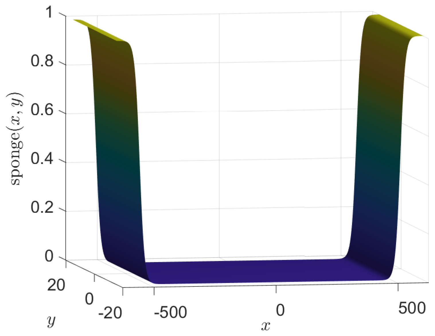
We show only a representative sample of the numerical results, in which the sponge layer in the x-direction is Equation (A7), with settings , , and ; a plot of the sponge layer is shown in Figure 1; there is no sponge layer in the y-direction in the displayed results. Cases 1 and 2 use the initial condition A and case 3 the second initial condition, B. After testing the sensitivity of the numerical resolution, we set and , the numbers of Fourier modes are and , and the time step is for all cases shown.
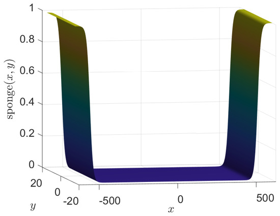
Figure 1.
The sponge layer near the ends of the x-domain.
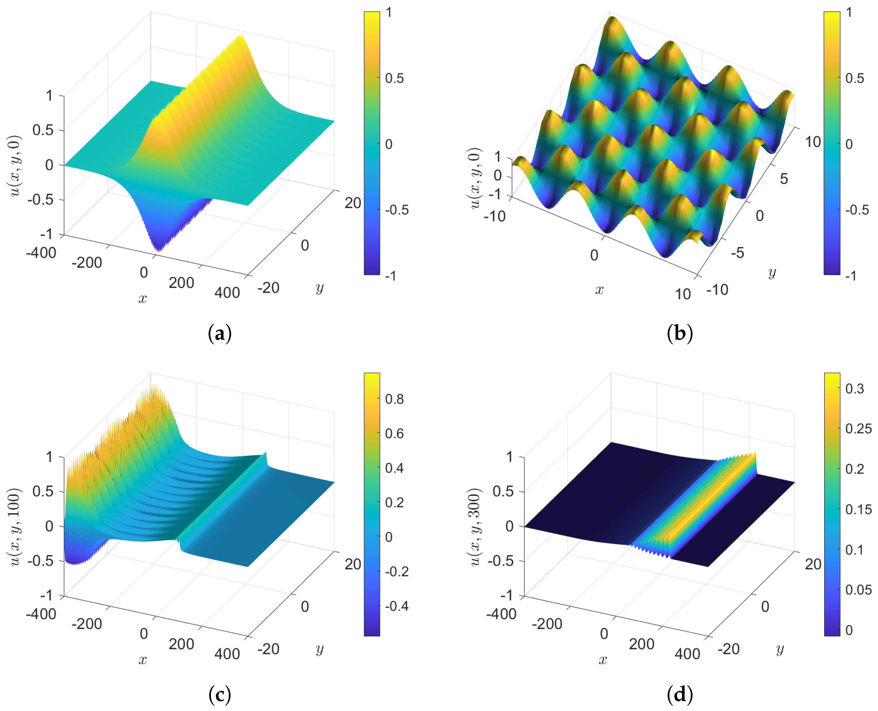
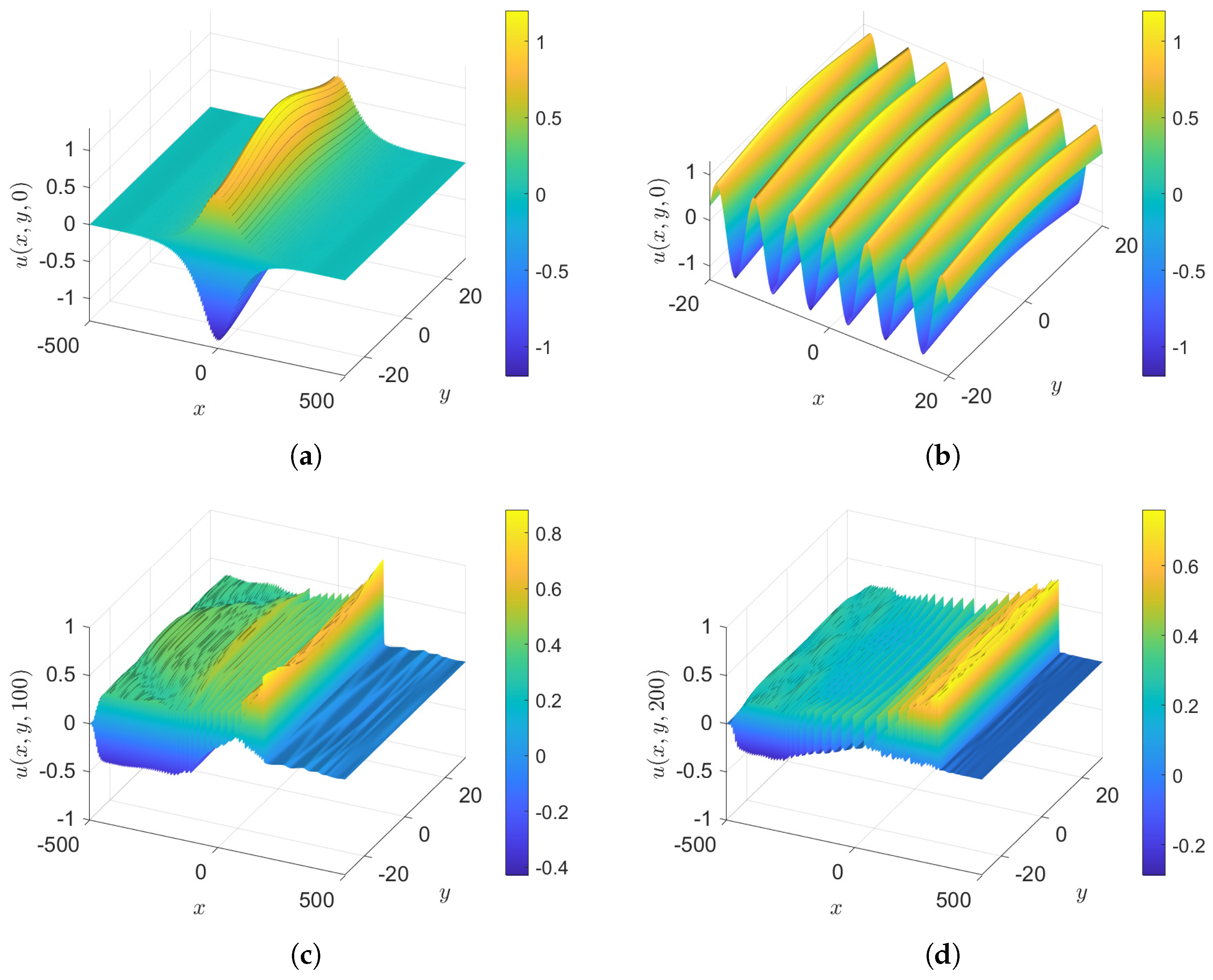
- Case 1: , with and , so that the initial condition, Equation (36), is . The results at various times for unforced cases are shown in Figure 2. The initial y-dependent sinusoidal function shapes the large radiation field in the y-direction, while in the x-direction it is primarily due to the envelope , and moves upstream, leaving the formation of a soliton gas downstream, which has no perceptible y-dependence, as clearly seen at .
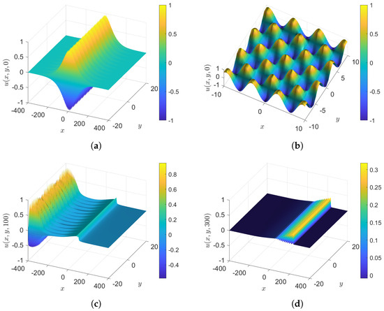 Figure 2. Case 1: The initial condition is , . (a) Perspective at ; (b) zoom at , (c) , and (d) .
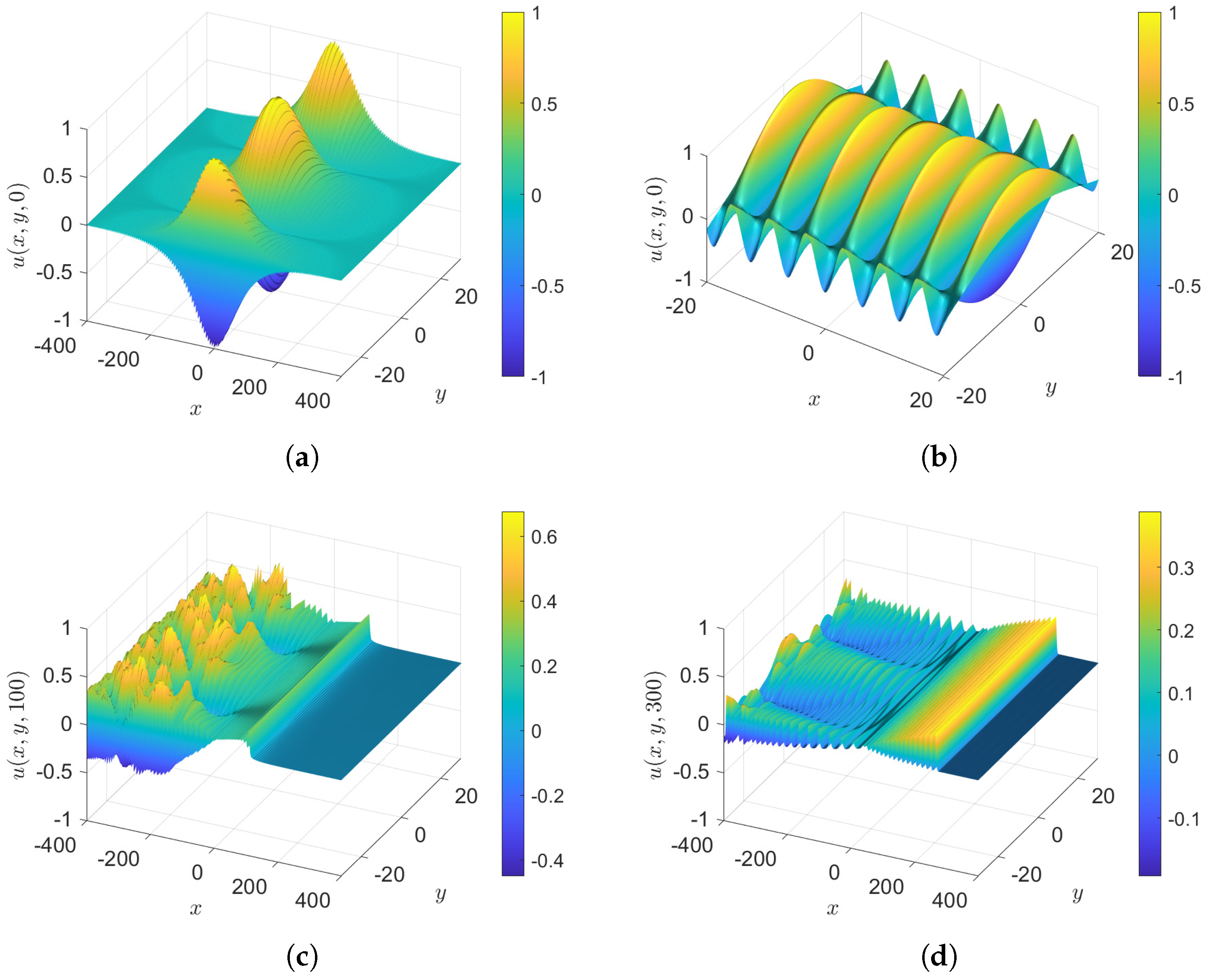
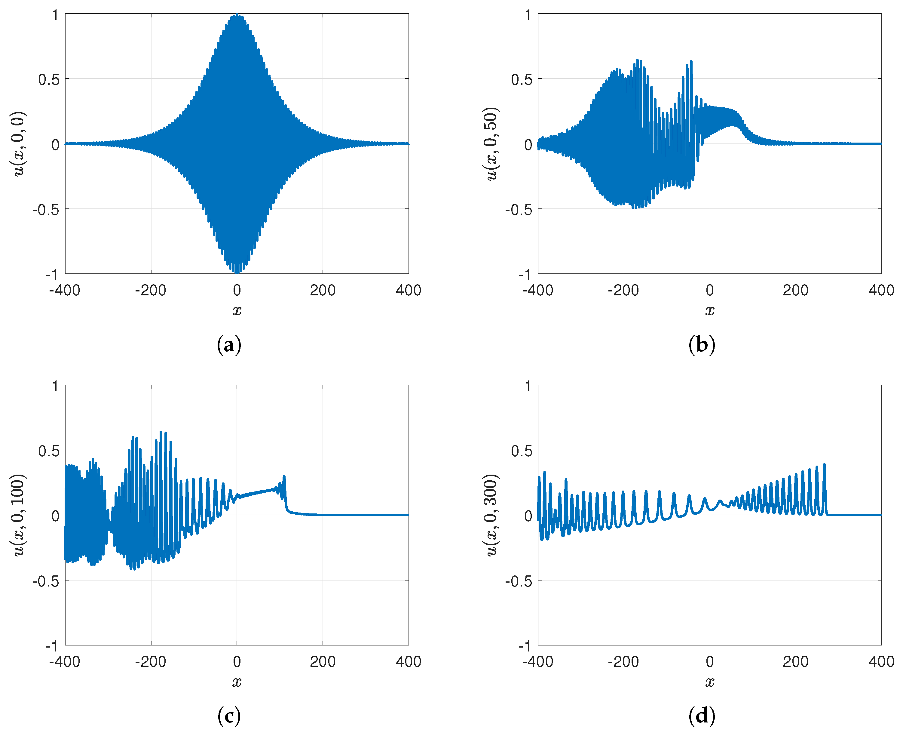
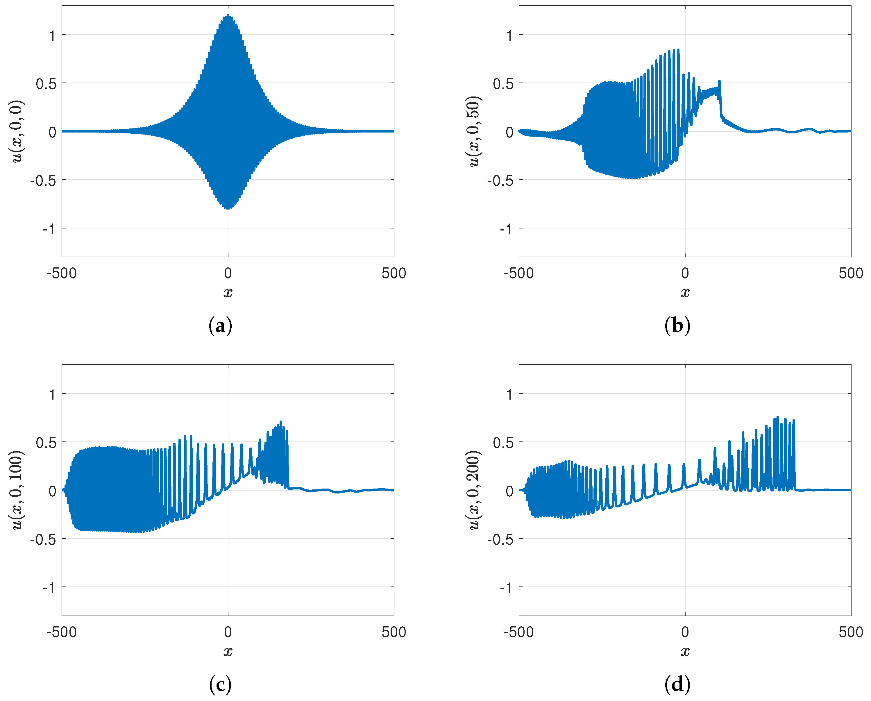
- Case 2: , with and , so that the initial condition, Equation (36), is . The difference from case 1 is that is greatly reduced, and in the sub-cases to follow we consider . Surface plots of unforced cases, , are shown in Figure 3 and the wave elevations along the x-axis when , both at various times, are shown in Figure 4. The outcome is similar to case 1 but with a slower sinusoidal y-dependence in the initial condition, which leads to some noise in the y-direction in the radiation field. However, this does not affect the y-independent soliton gas emerging downstream, as can be seen at .
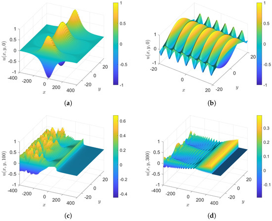 Figure 3. Case 2: The initial condition is , . (a) Perspective at ; (b) zoom at , (c) , and (d) .
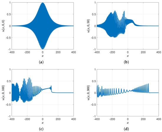 Figure 4. Case 2: The initial condition is , . The wave elevation along the x-axis when and (a) , (b) , (c) , and (d) .
We also tried a case when the initial condition had a mean level; that is, . The outcome, is comparable with case 2 above, and downstream solitons emerge as in MG24. We note here that if the x-envelope is replaced with a y-envelope, that is, , then high oscillations propagate in the y-direction.
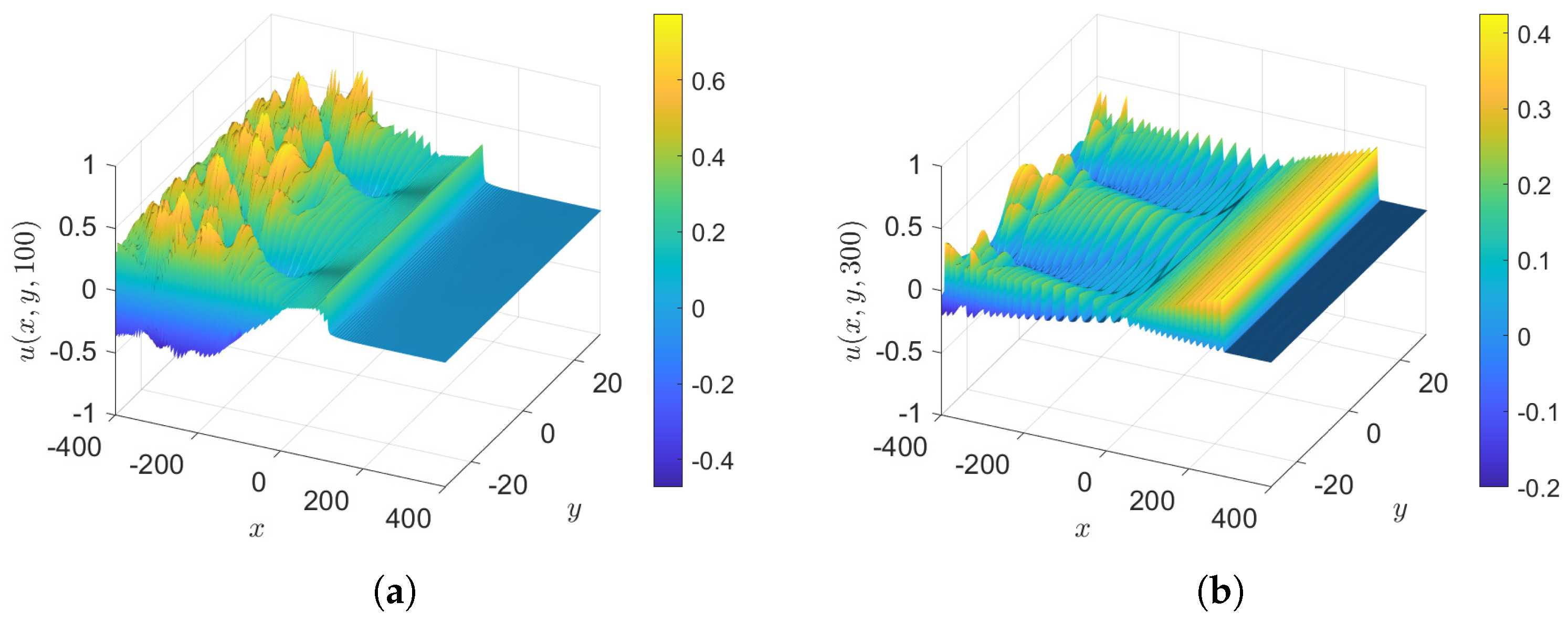
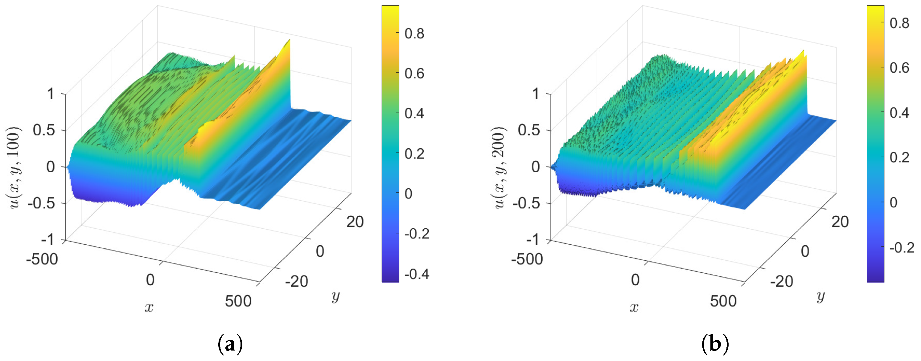
- Case 2.1: , with as in case 2, so that the initial condition is again . The results at various time are shown in Figure 5. This is similar to case 2, but with the expected wave growth due to .
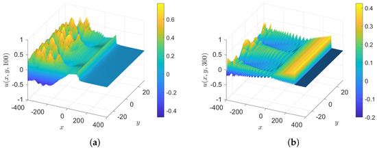 Figure 5. Case 2.1: The initial condition is , , . (a) and (b) .
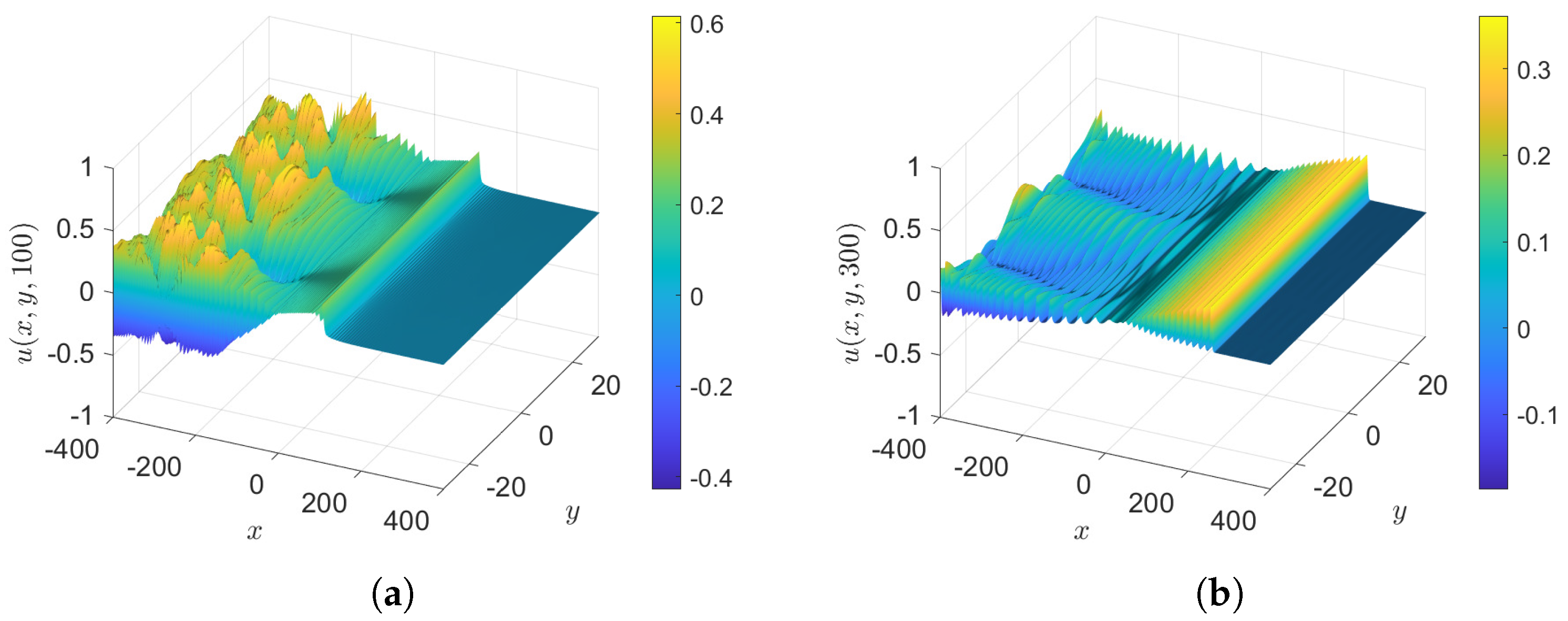
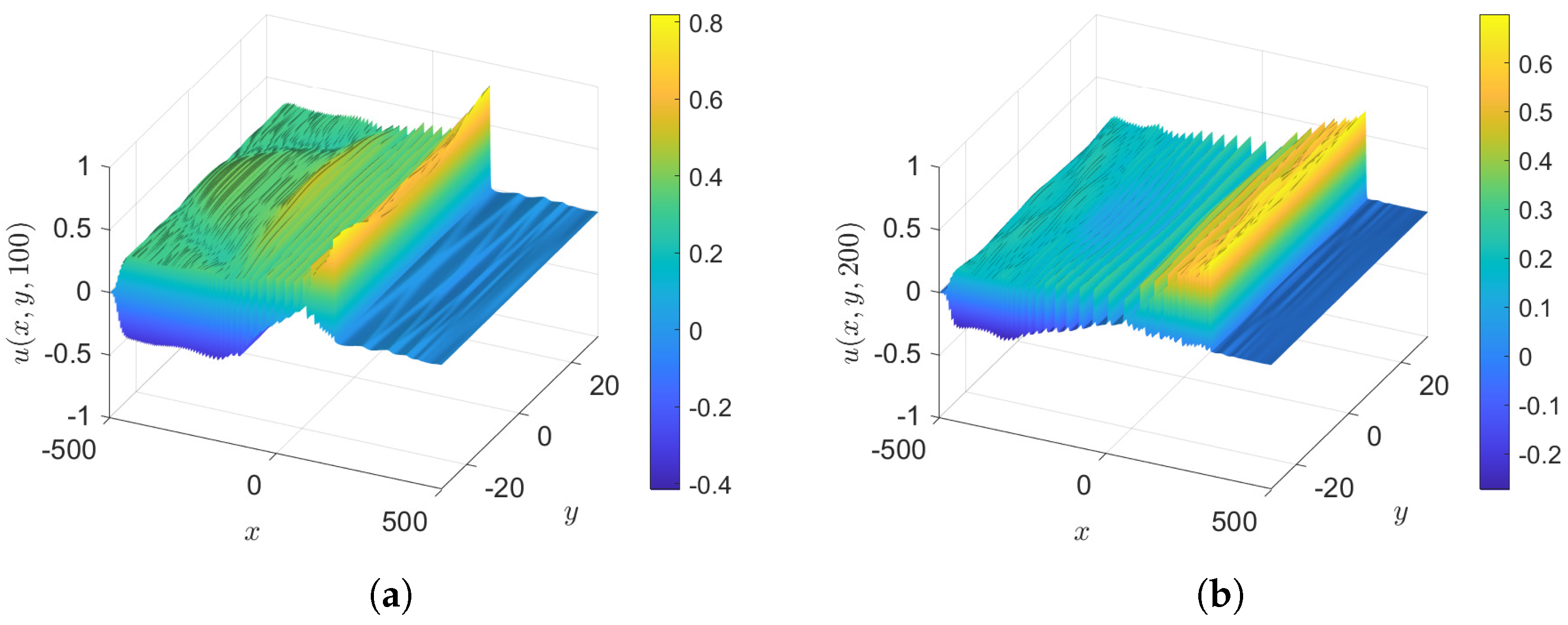
 - Case 2.2: , with as in case 2, so that the initial condition is again . The results at various times are shown in Figure 6. This is similar to case 2, but with the expected wave decay due to .
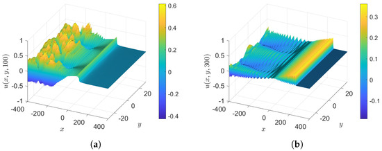 Figure 6. Case 2.2: The initial condition is , , . (a) and (b) .
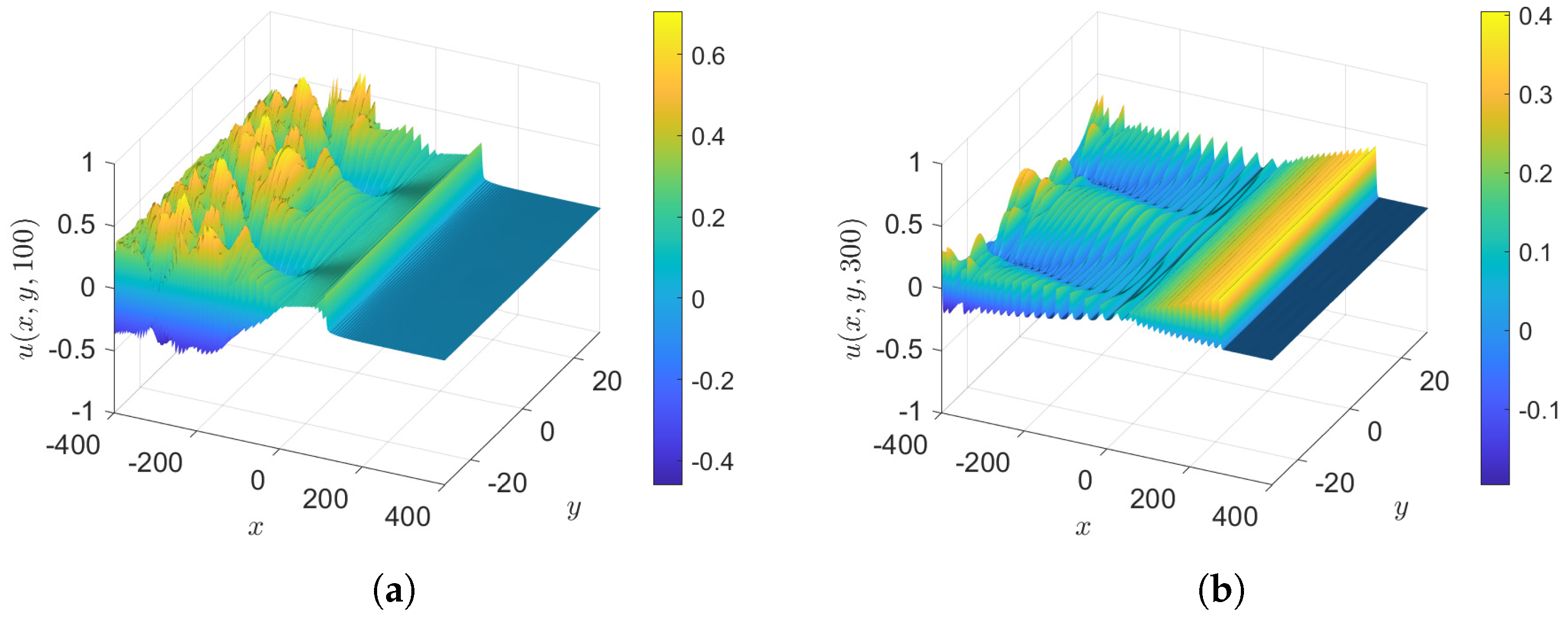
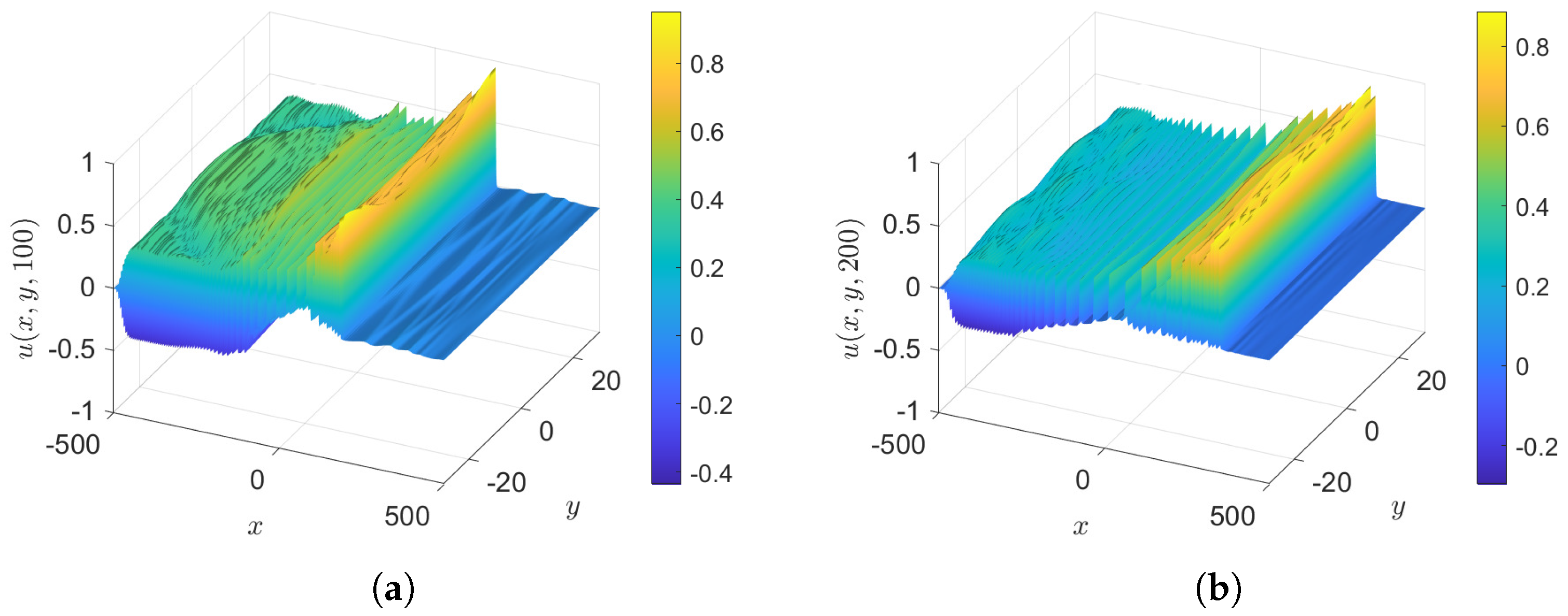
- Case 2.3: , with as in case 2, so that the initial condition is again . The results at various times are shown in Figure 7. This is similar to case 2, but with the expected growth due to .
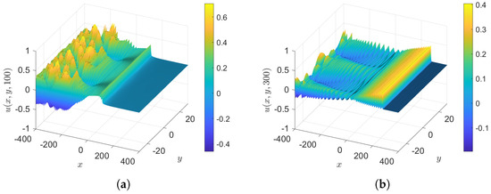 Figure 7. Case 2.3: The initial condition is , , . (a) and (b) .
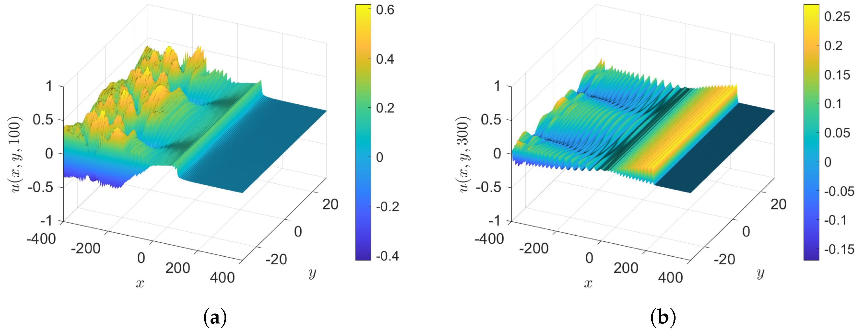
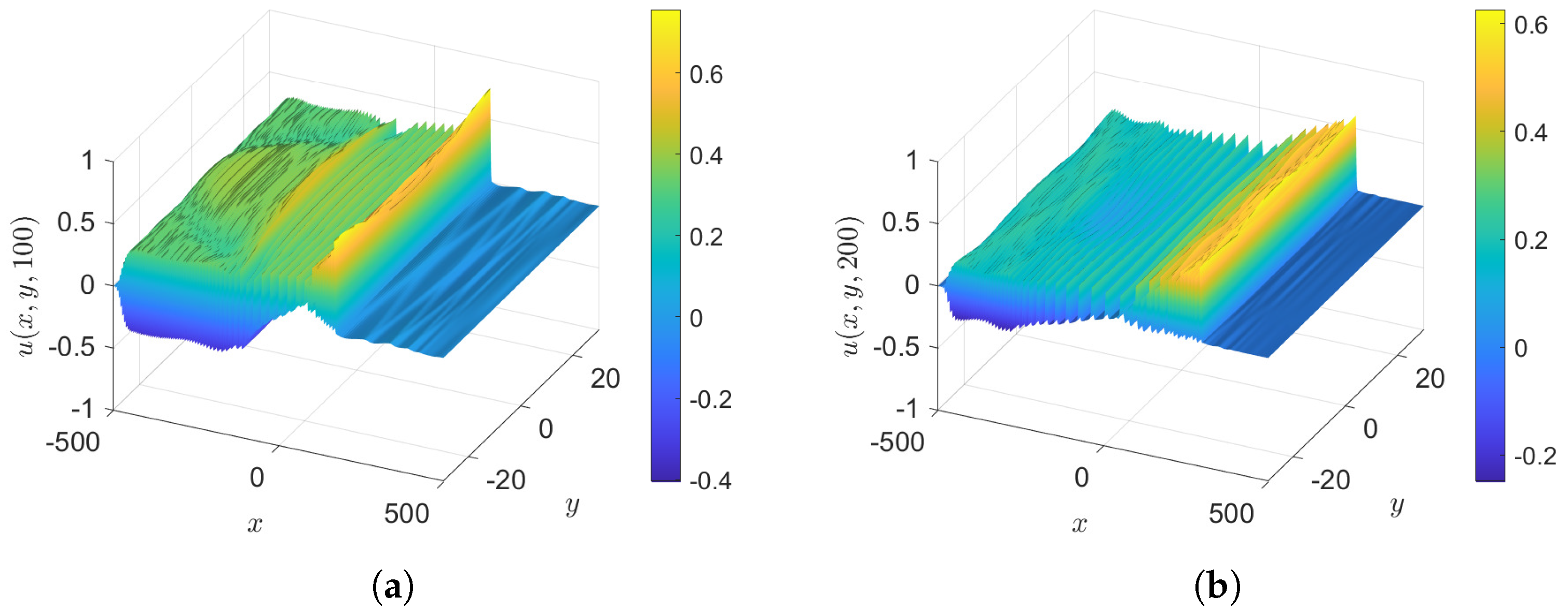
 - Case 2.4: . with as in case 2, so that the initial condition is again . The results at various times are shown in Figure 8. This is similar to case 2, but with the expected decay due to .
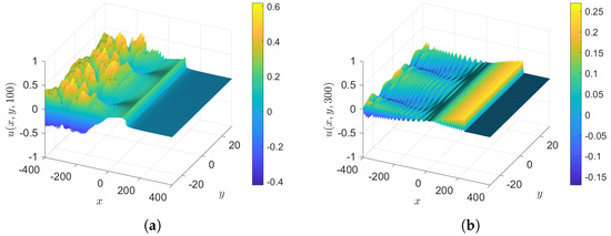 Figure 8. Case 2.4: The initial condition is , . (a) and (b) .
 - Case 2.5: , with as in case 2, so that the initial condition is again . The results at various times are shown in Figure 9. This case shows the dominant effect from bottom friction over , since the wave amplitude is decaying and the growth factors are suppressed, similar to the behaviour in MG24.
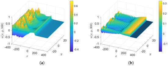 Figure 9. Case 2.5: The initial condition is , . (a) and (b) .
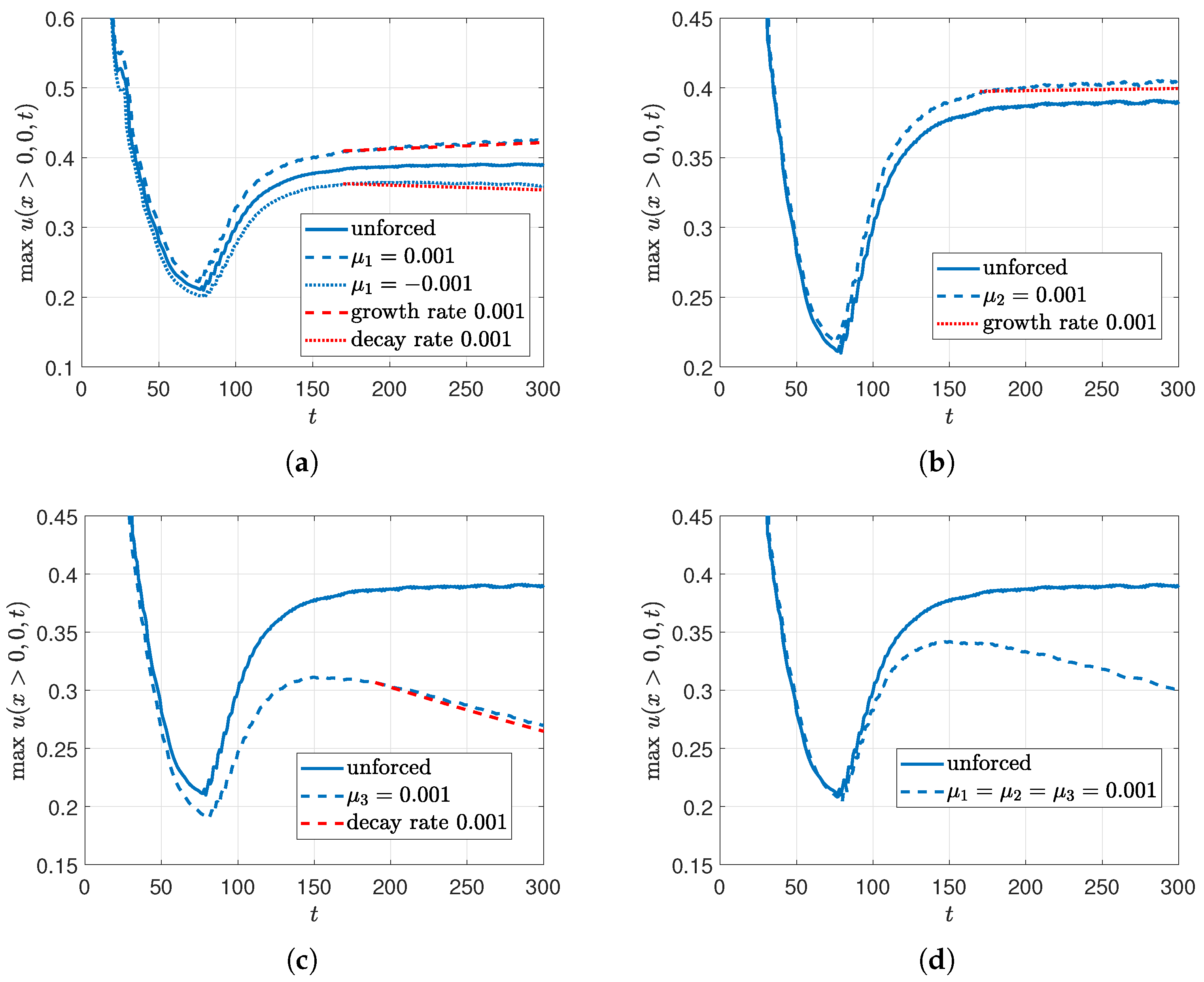
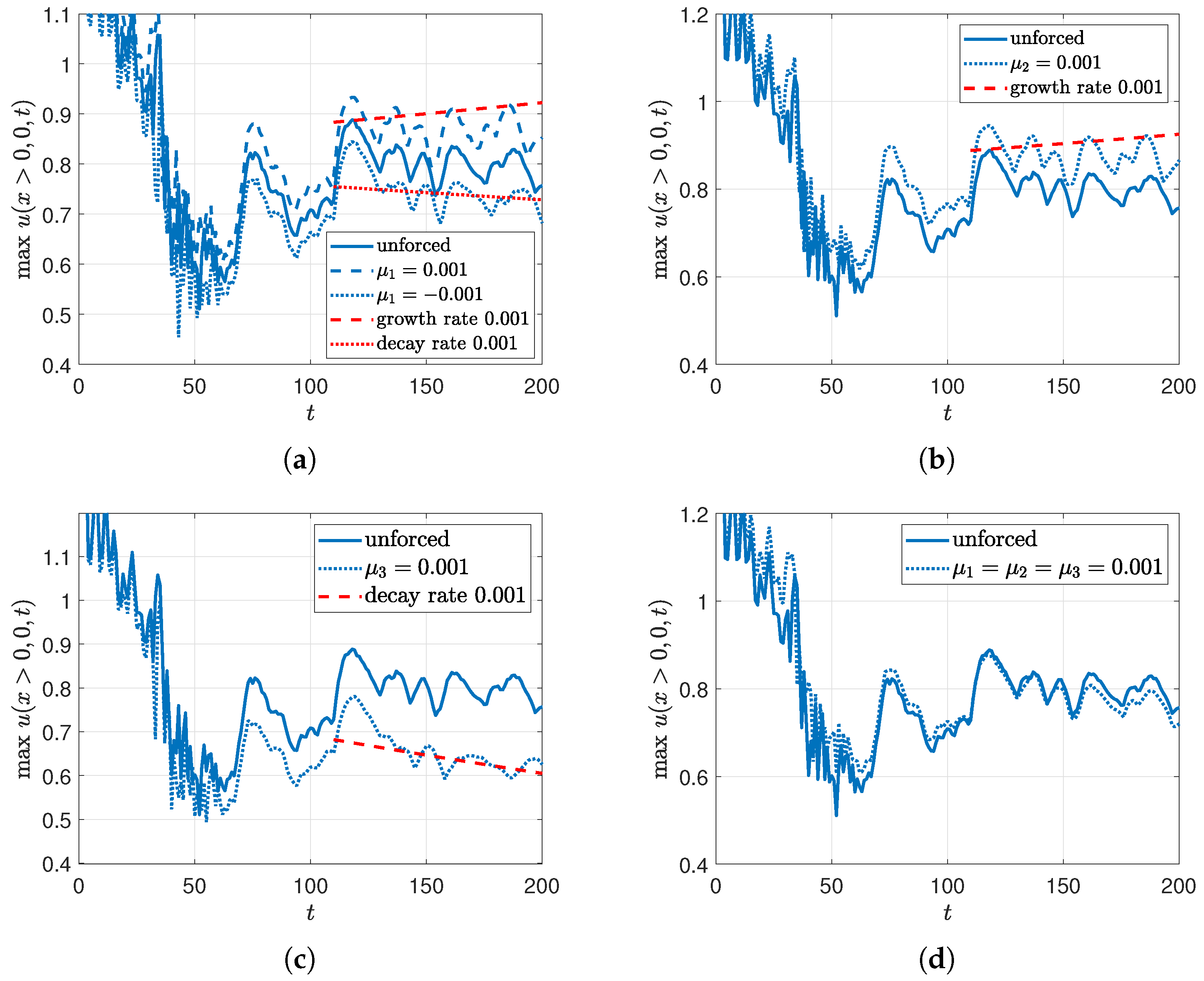
- Maximum amplitude, case 2: Figure 10 shows the tracking of the maximum value of , compared with the modulation theory of Section 3.3. Since the downstream solitons are apparently independent of y, the growth and decay rates are from the expressions in MG24. Overall, the maximum amplitudes are about half those in MG24, due to the greater radiation field.
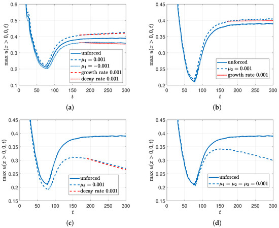 Figure 10. The initial condition is , tracking the maximum value of . (a) ; (b) ; (c) ; (d) .
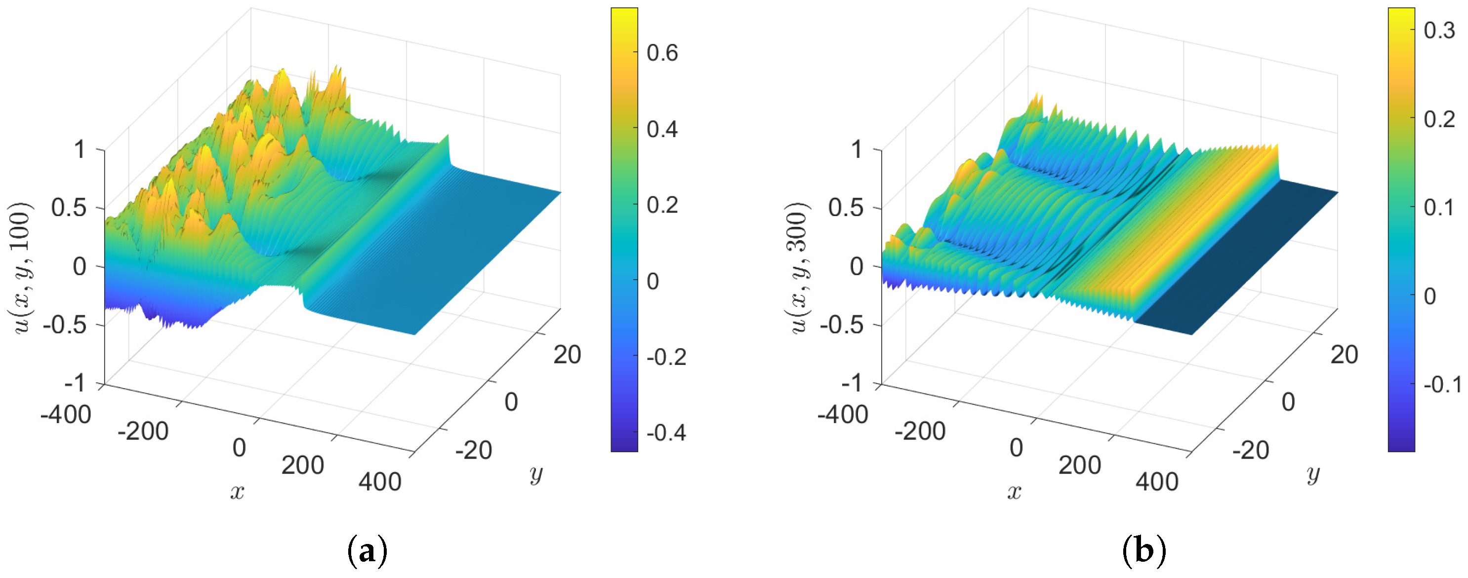
 - Case 3: , with and , so that the initial condition, Equation (36), is . Surface plots of unforced cases, , are shown in Figure 11 at various times and the wave elevations along the x-axis when are shown in Figure 12. The outcome is different to cases 1 and 2, with more oscillations in x of the generated train of solitons downstream, leading to a y-independent soliton gas emerging downstream, as can be seen at . The soliton amplitudes are larger than in cases 1 and 2. The amplitudes of the solitons in case 3 is about , comparable with MG24, while it is about 0.3–0.4 in cases 1 and 2. Hence, the soliton speeds are larger, and we stop the simulation at an earlier time, , to avoid the solitons approaching the right-hand x-boundary, where the sponge layer is applied. This is to avoid a misunderstanding in the tracking of the maximum soliton amplitude downstream.
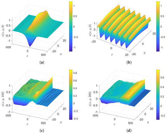 Figure 11. Case 3: The initial condition is , . (a) Perspective at ; (b) zoom at , (c) , and (d) .
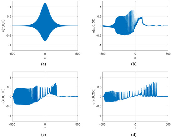 Figure 12. Case 3: The initial condition is , . The wave elevation along the x-axis when . (a) , (b) , (c) , and (d) .
 - Case 3.1: , with as in case 3, so that the initial condition is again . The results at various times are shown in Figure 13. This is similar to case 3, but with the expected wave growth due to .
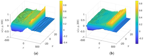 Figure 13. Case 3.1: The initial condition is , , . (a) and (b) .
 - Case 3.2: , with as in case 3, so that the initial condition is again . The results at various times are shown in Figure 14. This is similar to case 3, but with the expected wave decay due to .
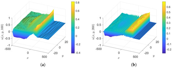 Figure 14. Case 3.2: The initial condition is , , . (a) and (b) .
 - Case 3.3: , with as in case 3, so that the initial condition is again . The results at various times are shown in Figure 15. This is similar to case 3, but with the expected growth due to .
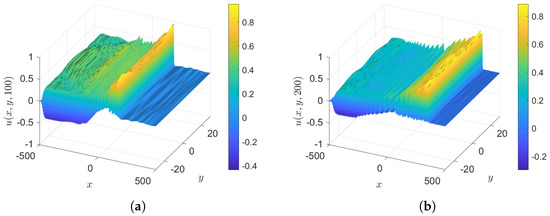 Figure 15. Case 3.3: The initial condition is , , . (a) and (b) .
- Case 3.4: , with as in case 3, so that the initial condition is again . The results at various times are shown in Figure 16. This is similar to case 3, but with the expected decay due to .
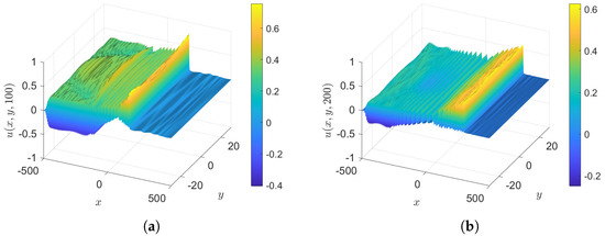 Figure 16. Case 3.4: The initial condition is , . (a) and (b) .
 - Case 3.5: , with as in case 3, so that the initial condition is again . The results at various times are shown in Figure 17.
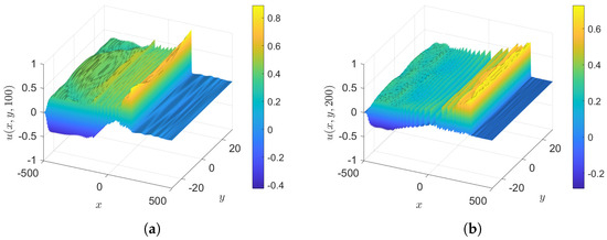 Figure 17. Case 3.5: The initial condition is , . (a) and (b) .
 - Maximum amplitude, case 3: Figure 18 shows the tracking of the maximum value of . Case 3, with a perturbation initial condition, leads to larger amplitudes than in the previous cases 1 and 2, as suggested by the modulation analysis of Section 3.3. However, the tracking maximum amplitude in case 3 is rather oscillatory, not monotonic as in case 2, indicating that this small y perturbation has slightly affected the growth or decay of the soliton amplitudes. Overall, the trends in the growth or decay rates in MG24 using modulation theory still give an indication of the numerical outcome. Curiously, when all the forcing terms are applied, the growth or decay of the leading soliton amplitude is not clearly seen for ; see Figure 18d. But the appearance of the maximum amplitude decreasing can be seen when , starting to show the effect of .
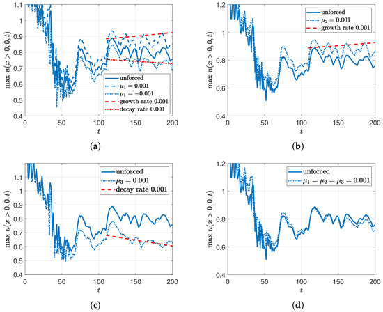 Figure 18. The initial condition is ; tracking the maximum value of . (a) , ; (b) ; (c) ; (d) .
5. Summary and Discussion
In this paper, we have extended the KdV–Burgers (KdVB) equation presented in [17] (MG24) to describe the evolution of wind-driven shallow-water waves by incorporating weak transverse dependence using the well-known Kadomtsev–Petviashvili (KPII) extension of the KdV equation. The outcome is Equation (1) in Section 2, which we have called the KP–Burgers (KPB) equation. Our objective is to examine how wind-generated shallow-water waves evolve in a two-dimensional horizontal space, and how the forcing/friction terms, Equations (2) and (3), in the KPB equation determine wave growth or decay. As in MG24, the forcing terms are due to the critical-level instability theory of Miles [5] (coefficient ), and a representation of turbulent wave stress in the air near the surface (coefficient ). The friction terms are due to a laminar boundary layer at the water surface (coefficient ), and a representation of turbulent bottom stress (coefficient ).
Our main aim was to examine the effect of transverse dependence on the soliton gas found in MG24 for the KdVB equation. Hence, in Section 3 we extended the modulation theory of MG24 for a periodic wave packet, emphasising, as in MG24, the solitary wave train limit. Although the modulation equations are now partial differential equations in time and two horizontal space dimensions, we established using various approximations and Riemann invariants to show that, as in MG24, the wind forcing coefficient with and wind wave stress with cause wave growth, and that dissipation occurs when , and that bottom stress with causes the wave amplitude to decay exponentially in time.
Numerical simulations are described in Section 4; the numerical scheme is an integrating-factor Fourier spectral method, described in the Appendix A. The theoretical predictions from the modulation theory are confirmed by these numerical simulations, using initial conditions, Equation (36), which are transverse modifications of the wave packet initial conditions used in MG24. We find that the KPB Equation (1) leads to the generation of a solitary wave train which forms a soliton gas, similar to the findings in MG24 for the one-dimensional case. The soliton gas remains stable even under transverse perturbations, although the presence of transverse perturbations amplifies the radiation field upstream. Interestingly, we note that Ablowitz and Curtis [18] found that a web-solution of the KPII equation perturbed by a reduction from the Benney–Luke equation developed an enhanced radiation field.
We conclude that the KdVB equation of MG24 and the KPB Equation (1) studied here are useful tools for studying wind waves in shallow water. Operationally, wind wave prediction is commonly based on the Hasselmann equation for the wave spectrum, which is in turn based on the four-wave resonant interactions in the Zakharov equation. These equations were developed for water of finite or infinite depth, and Zakharov [19] has shown that in the shallow-water limit they are formally valid only for for narrow or broad wave packets, respectively; here, , and h are the dimensional wavenumber, amplitude, and depth, respectively. This limitation is quite severe and suggests that in shallow water a different approach is needed. One possibility is to examine a Boussinesq system which is isotropic in the horizontal plane, unlike the KdVB equation or the KPB Equation (1). Ref. Onorato et al. [20] developed a kinetic theory of the original Boussinesq equations and compared it with the shallow-water limit of the Hasselmann equation with promising results, although issues about resonances in shallow water remain. Nevertheless, this would seem to be a fruitful direction for future research.
Author Contributions
Conceptualization, R.G.; methodology R.G.; software, M.M.; validation, R.G. and M.M.; formal analysis, R.G.; investigation, R.G. and M.M.; writing—original draft preparation R.G. and M.M.; writing—review and editing, R.G. and M.M.; visualization, M.M. All authors have read and agreed to the published version of the manuscript.
Funding
This research received no external funding.
Data Availability Statement
The raw data supporting the conclusions of this article will be made available by the authors on request.
Conflicts of Interest
The authors declare no conflicts of interest.
Appendix A. Numerical Scheme
The KPB Equation (1) is solved numerically using a spectral Fourier method with the integrating factor technique; see Klein and Roidot [15]. The periodic domains along the x and y-axes are and , respectively, where are multiples of , . The number of Fourier modes along the x- and y-axes are denoted by and , respectively. The arrays of wavenumbers in the x- and y-directions are denoted by and respectively.
Let , and . In case is very small, , we set . Let , then Equation (A1) becomes
Equation (A2) is an ordinary differential equation in , which can be solved in time by the Runge–Kutta method. After finding , we can find and finally can take the inverse Fourier transform of to obtain at every time step.
The Runge–Kutta method is applied to update the solution in the Fourier space,
where each is calculated as follows:
Here, f represents the combination of the nonlinear functions and in Equation (A2).
To handle aliasing from nonlinear terms, a dealiasing technique is applied when calculating and in Equation (A3); see Boyd [21]. We define the dealiasing function by , where mask is given by
We then use instead of in Equation (A3) when using the dealiasing process.
The boundary conditions in both the x- and y-domains are periodic in the Fourier basis. Since we investigate envelope waves and trains of solitons mainly travel along the x-direction, we apply the sponge layer technique to absorb radiating waves moving to the far field near the x-boundaries while maintaining periodicity. The sponge layer function in the x-direction is defined by
where , controls the width of the sponge layer from the ends of boundaries, is the magnitude of the sponge layer, and controls the smoothness. This sponge function is replicated uniformly across the y-direction. Hence, we obtain the sponge layer function in two dimensions, denoted by . We have not applied a sponge layer in the y-direction, leaving this as periodic in the smaller domain of y.
We cannot apply the sponge layer directly in the Fourier space of the Runge–Kutta method, and so instead we apply the sponge layer in the physical space. At each time step after obtaining from Equation (A3), we calculate
Then, we apply the sponge layer to zero out the updated solutions near the x-boundaries by
Finally, is transformed back into the Fourier space again to update for the next time step.
In the Fourier spectral space, formally the global mass is , and there is no equation for ; see Equation (A1). As explained in the discussion of the mass constraint following Equation (6) in Section 2, when we require that on the boundaries , then . But, as explained there, if we only require that u is periodic in y, then can vary with t.
References
- Costa, A.; Osborne, A.R.; Resio, D.T.; Alessio, S.; Chrivi, E.; Saggese, E.; Bellomo, K.; Long, C.E. Soliton turbulence in shallow water ocean surface waves. Phys. Rev. Lett. 2014, 113, 108501. [Google Scholar] [CrossRef] [PubMed]
- Zdyrski, T.; Feddersen, F. Wind-induced changes to surface gravity wave shape in shallow water. J. Fluid Mech. 2021, 903, A27. [Google Scholar] [CrossRef]
- Manna, M.A.; Latifi, A. Korteweg de Vries Burger equation with Jeffreys wind wave interaction: Blow-up and breaking of soliton-like solutions in finite time. Fluids 2023, 8, 231–244. [Google Scholar] [CrossRef]
- Maleewong, M.; Grimshaw, R. Evolution of water wave packets by wind in shallow water. J. Fluid Mech. 2024, 996, A4. [Google Scholar] [CrossRef]
- Miles, J.W. On the generation of surface waves by shear flows. J. Fluid Mech. 1957, 3, 185–204. [Google Scholar] [CrossRef]
- Biondini, G.; Pelinovsky, D.E. Kadomtsev-Petviashvili equation. Scholarpedia 2008, 3, 6539. [Google Scholar] [CrossRef]
- Chakravarty, S.; Kodama, Y. Classification of the line-soliton solutions of KPII. J. Phys. A Math. Theor. 2008, 41, 275209. [Google Scholar] [CrossRef]
- Ablowitz, M.J.; Villarroel, J. On the Kadomtsev-Petviashvili equation and associated constraints. Stud. Appl. Math. 1991, 85, 195–231. [Google Scholar] [CrossRef]
- Molinet, L.; Saut, J.C.; Tzvetkov, N. Remarks on the mass constraint for KP-type equations. SIAM J. Math. Anal. 2007, 39, 627–641. [Google Scholar] [CrossRef][Green Version]
- Osborne, A.R. Shallow water cnoidal wave interactions. Nonlinear Processes Geophys. 1994, 1, 241–251. [Google Scholar] [CrossRef]
- Ablowitz, M.J.; Biondini, G.; Wang, Q. Whitham modulation theory for the Kadomtsev Petviashvili equation. Proc. Roy. Soc. A 2017, 473, 20160695. [Google Scholar] [CrossRef] [PubMed]
- Grava, T.; Klein, C.; Pittori, G. Numerical study of the Kadomtsev-Petviashvili equation and dispersive shock waves. Proc. Roy. Soc. A 2018, 474, 20170458. [Google Scholar] [CrossRef]
- Ryskamp, S.; Hoefer, M.; Biondini, G. Modulation theory for soliton resonance and Mach reflection. Proc. Roy. Soc. A 2022, 478, 20210823. [Google Scholar] [CrossRef]
- Grimshaw, R.; Yuan, C. The propagation of internal undular bores over variable topography. Phys. D 2016, 333, 200–207. [Google Scholar] [CrossRef][Green Version]
- Klein, C.; Roidot, K. Fourth order time-stepping for Kadomtsev-Petviashvili and Davey-Stewartson equations. SIAM J. Sci. Comput. 2011, 33, 3533–3556. [Google Scholar] [CrossRef]
- Kao, C.Y.; Kodama, Y. Numerical study of the KP equation for non-periodic waves. Math. Comput. Simul. 2012, 82, 1185–1218. [Google Scholar] [CrossRef]
- Maleewong, M.; Grimshaw, R. Evolution of water wave groups in water of finite depth. J. Fluid Mech. 2024, 985, A2. [Google Scholar] [CrossRef]
- Ablowitz, M.J.; Curtis, C.W. On the evolution of perturbations to solutions of the Kadomtsev Petviashvilli equation using the Benney Luke equation. J. Phys. A Math. Theor. 2011, 44, 195202. [Google Scholar] [CrossRef]
- Zakharov, V.E. Statistical theory of gravity and capillary waves on the surface of a finite-depth fluid. Eur. J. Mech. B/Fluids 1999, 18, 327–344. [Google Scholar] [CrossRef]
- Onorato, M.; Osborne, A.R.; Jannsen, P.A.E.M.; Resio, D. Four-wave resonant interactions in the classicalquadratic Boussinesq equations. J. Fluid Mech. 2009, 618, 263–277. [Google Scholar] [CrossRef]
- Boyd, J.P. Chebyshev and Fourier Spectral Methods; Dover: New York, NY, USA, 2001. [Google Scholar]
Disclaimer/Publisher’s Note: The statements, opinions and data contained in all publications are solely those of the individual author(s) and contributor(s) and not of MDPI and/or the editor(s). MDPI and/or the editor(s) disclaim responsibility for any injury to people or property resulting from any ideas, methods, instructions or products referred to in the content. |
© 2025 by the authors. Licensee MDPI, Basel, Switzerland. This article is an open access article distributed under the terms and conditions of the Creative Commons Attribution (CC BY) license (https://creativecommons.org/licenses/by/4.0/).

