Article

An Application of Upwind Difference Scheme with Preconditioned Numerical Fluxes to Gas-Liquid Two-Phase Flows

1
Interdisciplinary Graduate School of Agriculture and Engineering, University of Miyazaki, Miyazaki 889-2192, Japan
2
Department of Mechanical Engineering, University of Miyazaki, Miyazaki 889-2192, Japan
*
Author to whom correspondence should be addressed.
Fluids 2025, 10(2), 38; https://doi.org/10.3390/fluids10020038
Submission received: 30 November 2024 / Revised: 26 January 2025 / Accepted: 30 January 2025 / Published: 1 February 2025
(This article belongs to the Special Issue Advances in Multiphase Flow Science and Technology, 2nd Edition)

Abstract

:
A time-consistent upwind difference scheme with a preconditioned numerical flux for unsteady gas-liquid multiphase flows is presented and applied to the analysis of cavitating flows. The fundamental equations were formulated in general curvilinear coordinates to apply to diverse flow fields. The preconditioning technique was applied specifically to the numerical dissipation terms in the upwinding process without changing the time derivative terms to maintain time consistency. This approach enhances numerical stability in unsteady multiphase flow computations, consistently delivering time-accurate solutions compared to conventional preconditioning methods. A homogeneous gas-liquid two-phase flow model, third-order Runge-Kutta method, and the flux difference splitting upwind scheme coupled with a third-order MUSCL TVD scheme were employed. Numerical tests of two-dimensional gas-liquid single- and two-phase flows over backward-facing step with different step height and flow conditions successfully demonstrated the capability of the present scheme. The calculations remained stable even for flows with a very low Mach number of 0.001, typically considered incompressible flows, and the results were in good agreement with the experimental data. In addition, we analyzed unsteady cavitating flows at high Reynolds numbers and confirmed the effectiveness and applicability of the present scheme for calculating unsteady gas-liquid two-phase flows.

1. Introduction

Gas-liquid multiphase flows, where liquid and gas phases coexist, have garnered continuous interest in fields such as mechanical engineering, naval and marine engineering, and nuclear engineering. These flows are found in problems such as cavitation in fluid machinery (such as rocket engine turbopumps and high-speed underwater vehicles), boiling in nuclear reactor cooling systems, free surface flows, underwater explosions, and sloshing in storage tanks. Gas-liquid multiphase flows exhibit a mix of compressible and incompressible flow characteristics, with a wide range of density and sound speed changes. These properties induce local changes in the type of differential equation of the governing equations, making their numerical analysis is very difficult. In many cases, numerical analysis for gas-liquid two-phase flow has been attempted mainly using a two-fluid model and a pseudo-single-phase homogeneous medium model. The two-fluid model is divided into interface-tracking methods, such as front-tracking [1] and Arbitrary Lagrangian-Eulerian (ALE) [2] methods, and interface-capturing methods, including the volume-of-fluid (VOF) [3,4,5] and level set [6] methods. This model captures the gas-liquid interface with high accuracy and is widely used to analyze bubbly flows in boiling problems, and free surface flows. However, depending on the methods, this model requires a sufficient number of grids to resolve the interface, and the governing equations for the gas and liquid phases are solved separately, resulting in a large computational load and making it unsuitable for analyzing complex, high-speed flows, such as those inside fluid machinery. In contrast, the homogeneous medium model represents a multiphase state by treating the gas and liquid phases within a computational cell as a single homogeneous medium. While it cannot accurately capture the interfaces, this model offers a reduced computational load due to its pseudo-single-phase treatment. Its versatility makes it a preferred choice for most simulations in the design and development of fluid machinery. As seen above, each model has its advantages and disadvantages, but with appropriate selection, they have been successfully applied to their respective engineering problems.
Another important issue in calculating these flows is the simultaneous consideration of both compressible and incompressible flow properties. However, numerical methods designed exclusively for either compressible or incompressible flow methods face inherent limitations in calculating flows that contain both compressible and incompressible properties. In recent years, attention has been focused on the preconditioning method [7,8] for this issue. By introducing preconditioning techniques into the fundamental equations for multiphase flows and developing a numerical method that takes into account pseudo-sound speeds, it has become possible to analyze these types of flows, including cavitating flows [9,10,11]. However, conventional preconditioning methods generally modify the time derivative terms, which, while improving accuracy and convergence in steady-flow computations, introduce challenges to time accuracy in unsteady flow simulations. These problems have been resolved by introducing a dual time-step procedure and improving the preconditioning method to be time-consistent, allowing unsteady flows to be computed [12,13,14,15]. However, although this dual time-step preconditioning method is useful for solving unsteady flows, it requires long computing times to obtain the solutions.
Recently, to reduce the computing times and increase computational efficiency, the present authors [16] proposed a stable and effective upwind scheme, applying preconditioning for solving unsteady gas-liquid multiphase flow problems. In this scheme, because only numerical dissipation terms in the upwinding process are modified using a preconditioning matrix, without modifying the time derivative terms, this scheme always provides a time-consistent solution. The effectiveness and applicability of this scheme in unsteady flow computations were confirmed through its application to one-dimensional (1-D) gas-liquid two-phase shock tube flow problems.
In this paper, we extend the previously proposed effective upwind scheme [16] to a two-dimensional (2-D) time-consistent scheme to solve unsteady gas-liquid two-phase flows and investigate its validity and capability for multidimensional problems. The fundamental equations are derived in a general curvilinear coordinate system to be applied in a variety of flow fields. To obtain a stable and accurate treatment of gas-liquid interfaces, the third-order MUSCL TVD scheme is applied. The flux Jacobian matrix, its eigenvalues, and eigenvectors for upwinding are derived by introducing preconditioning. 2-D gas-liquid two-phase flows in backward-facing step channels with different expansion ratios and different flow conditions, including cavitation numbers, are computed. The effectiveness and capability of the present scheme for multidimensional flow problems are evaluated.

2. Numerical Methods

2.1. Governing Equations

In this study, the governing equations for 2-D gas-liquid two-phase flow are compressible Navier-Stokes equations, which express mixture mass, momentum, energy, and gas-phase mass conservation equations in a curvilinear coordinate system [15] and can be written as follows:
Q t + F i ξ i = F ν i ξ i + S   with   Q = J ρ ρ u ρ v e ρ Y ,   F i = J ρ U i ρ u U i + ξ i / x p ρ v U i + ξ i / y p ρ U i H ρ U i Y , F ν i = J 0 ξ i / x j τ x j ξ i / x j τ y j ξ i / x j u k τ k j + κ T / x j 0   ( i ,   j ,   k = 1 ,   2 ) ,   S = J 0 0 0 0 S e S c , and   J = x ξ y η x η y ξ .
where Q and F i ( F , G ) are conservative variables and flux vectors, respectively. F ν i ( F v , G v ) and S indicate diffusion and source terms, respectively. ρ , p , T , Y , and e denote the mixtured density, pressure, temperature, quality of vapor, and total energy, respectively. u i ( u , v ) and U i ( U , V ) present physical and contravariant velocity components defined by U i = ( ξ i / x j ) u j . τ i j and κ are the stress tensor and coefficient of thermal conductivity, respectively. H is the enthalpy defined by H = ( e p ) / ρ . J is the Jacobian for the transformation from Cartesian coordinates x i ( x , y ) to curvilinear coordinates ξ i ( ξ , η ) . S e and S c in source terms indicate the rates of evaporation (vapor generation) and condensation (vapor conversion to liquid), respectively. Furthermore, the following equation of state, derived using a homogeneous equilibrium model for gas-liquid mixture [17], is applied:
ρ = p p + p c K 1 Y p T + T c + R Y p + p c T
In the above equation, K , p c , and T c represent the liquid, pressure, and temperature constants for water, respectively, and R is the gas constant. In this two-phase flow model, the apparent compressibility is taken into account, and the speed of sound c in two-phase media is derived as c 2 = ρ C p / ( ρ / T + ρ C p ρ / p ) [16]. Here, C p is the specific heat capacity at a constant pressure of the gas-liquid two-phase medium. Additionally, the relation between the local void fraction α and quality of the vapor Y is given as
α = R Y p + p c T K 1 Y p T + T c + R Y p + p c T

2.2. Preconditioned Governing Equations

Gas-liquid multiphase flows, such as cavitating flows, contain properties of both incompressible and compressible flows and are very difficult to solve using either the compressible or incompressible flow method alone. To solve such flows, it is computationally expedient to revise compressible flow methods so that incompressible flows with an extremely low Mach number can be solved. For this, artificial compressibility methods [18,19] and preconditioning methods [20] have been developed. Originally, these methods are designed to deal with steady flow problems and are not suitable for time-dependent problems because the time consistency of the time derivative terms are destroyed by the preconditioning. Recently, the preconditioning method has been improved with a dual time-stepping method [13,15,21], making it possible to compute time dependent flow problems. However, even though this improved preconditioning method can solve unsteady flow problems, it takes significant computational time to obtain a meaningful solution. To avoid such shortcomings, we recently proposed a stable and efficient preconditioning method for unsteady gas-liquid multiphase flows [16].
This research extends this time-consistent preconditioning method to a 2-D flow method in general curvilinear coordinate systems. To achieve this, a similar approach to the previously proposed method is adopted [16] by rewriting the governing Equation (1). Specifically, the transformation of the unknown variables from conserved variables Q to primitive variables W as follows:
Γ w 1 W t + F i ξ i = R where   R = F ν i ξ i + S ,   W = [ p ,   u , v ,   T ,   Y ] T   and   Γ w 1 = Q W .
Then preconditioning of this equation is done by replacing the transform matrix Γ w 1 in Equation (4) with the preconditioning matrix Γ p 1 to treat both incompressible and compressible flow problems. Here, Γ p 1 is derived by adding the vector θ 1 , u , v , H , Y T to the first column of the transform matrix Γ w 1 [9,13] as follows:
Γ p 1 = J θ + ρ / p 0 0 ρ / T ρ / Y u θ + ρ / p v θ + ρ / p ρ 0 0 ρ u ρ / T v ρ / T u ρ / Y v ρ / Y H θ + ρ / p 1 ρ u ρ v ρ C p + H ρ / T H ρ / Y Y θ + ρ / p 0 0 Y ρ / T ρ + Y ρ / Y
where θ is a preconditioning weight parameter designed to handle all the incompressible and compressible flows and defined as 1 / a 2 1 / c 2 with a a 2 = m i n [ c 2 , max u i 2 , β U 0 2 ] . β is an empirical constant, and U 0 is a reference velocity such as an inlet mean velocity.

2.3. Upwinding and Numerical Flux

In this paper, to improve numerical stability in the computation of two-phase multiphase flows with large density changes, an upwinding on the advection terms is implemented using Roe’s flux-difference splitting (FDS) scheme [22]. In this case, the derivative of flux vectors F in Equation (4) with respect to ξ at point l , for example, can be written as ( F / ξ ) l = ( F l + 1 / 2 F l 1 / 2 ) / ξ , and the numerical flux F l ± 1 / 2 is approximated as:
F l ± 1 / 2 = 1 2 F ( Q l ± 1 / 2 L ) + F ( Q l ± 1 / 2 R ) | A | l ± 1 / 2 ( Q l ± 1 / 2 R Q l ± 1 / 2 L )
In Equation (6), the Roe matrix | A | l ± 1 / 2 is a numerical dissipation terms consisting of the flux Jacobian matrix A ( = F / Q ) for numerical stability in upwinding processes, and it is evaluated by the Roe-average [22]. Conversely, as explained in our previous paper [16], preconditioning Equation (4) using the preconditioning matrix Γ p 1 instead of the transform matrix Γ w 1 , and subsequently linearizing the flux vectors using the flux Jacobian matrix and rewriting them into hyperbolic form, yields the following preconditioned governing equations:
W t + A ^ i W ξ i = Γ p R   with   A ^ i = Γ p A i Γ w 1
where A ^ i are preconditioned flux Jacobian matrices and Γ p is the inverse matrix of Γ p 1 . In the upwinding, the advection term of the system W is transformed back into a conservative system of variables Q [16]. Hence, the derivative of the flux vector F / ξ is transformed by using A ^ as
F ξ = Γ p 1 A ^ Γ w Q ξ = A ~ Q ξ
where, Γ w is the inverse matrix of Γ w 1 . Therefore, similar to Equation (6), by applying Roe’s FDS to Equation (8), the preconditioned numerical fluxes F l ± 1 / 2 can be written as follows:
F l ± 1 / 2 = 1 2 F ( Q l ± 1 / 2 L ) + F ( Q l ± 1 / 2 R ) A ~ l ± 1 / 2 ( Q l ± 1 / 2 R Q l ± 1 / 2 L )
Meanwhile, in computing A ~ in Equation (9), the properties of the matrix A ^ are utilized. The preconditioned matrix A ^ has real eigenvalues and can be diagonalized in the form A ^ = L ^ Λ ^ L ^ 1 . Ultimately, the preconditioned numerical flux F l ± 1 / 2 in Equation (9) is derived as follows:
F l ± 1 / 2 = 1 2 F ( Q l ± 1 / 2 L ) + F ( Q l ± 1 / 2 R ) { Γ p 1 L ^ | Λ ^ | L ^ 1 Γ w } l ± 1 / 2 ( Q l ± 1 / 2 R Q l ± 1 / 2 L )
where Λ ^ in the numerical dissipation term is a diagonal matrix of characteristic speeds (eigenvalues) of the preconditioned matrix A ^ , and L ^ and L ^ 1 are matrices consisting of the left eigenvectors of A ^ and their inverses, respectively. Λ ^ and L ^ are concretely derived as follows:
Λ ^ = U 0 0 0 0     0 U + c ~ 0 0 0     0 0 U 0 0     0 0 0 U c ~ 0     0 0 0 0 U   and   L ^ = 1 1 0 1 0     0 ξ x l + ξ y ξ x l ξ y     0 ξ y l + ξ x ξ y l ξ x     ρ C p 0 0 0 0     0 0 0 0 1
where,
± c ~ = 1 / 2 B B 2 + 4 A c 2 g 11 , A = ρ / T + ρ C p ρ / p ρ / T + ρ C p ( θ + ρ / p ) ,   B = U ρ C p θ ρ / T + ρ C p ( θ + ρ / p ) , l ± = ρ c 2 A / ± c ~ ,   g 11 = ξ x 2 + ξ y 2   and   ξ x = ξ x ,   ξ y = ξ y .
In Equation (11), when θ = 0 without preconditioning, the apparent sound speed ± c ~ becomes ± c g 11 , and the eigenvalues and eigenvectors of the preconditioned flux Jacobian matrix are returned to their traditional form of A for nonpreconditioned system. As shown in Equation (5), because θ is controlled according to the speed of flow and the stiff problems are eliminated, Equation (4) employing the preconditioned numerical flux of Equation (10) for upwinding can solve flows with both incompressible and compressible flow characteristics [9,13]. The derivative of G with respect to η can be obtained in a similar manner.
Meanwhile, conserved variables Q l + 1 / 2 L and Q l + 1 / 2 R in Equation (10) are reconstructed from the primitive variables W l + 1 / 2 L and W l + 1 / 2 R , which are obtained using the MUSCL TVD scheme [23] as follows:
      W l + 1 / 2 L = W l + 1 / 4 { 1 κ D + W l 1 / 2 + 1 + κ D W l + 1 / 2 } W l + 1 / 2 R = W l + 1 1 / 4 { 1 κ D W l + 3 / 2 + 1 + κ D + W l + 1 / 2 }
where,
D + W l 1 / 2 = m i n m o d δ W l 1 / 2 , b δ W l + 1 / 2 , D W l + 1 / 2 = m i n m o d δ W l + 1 / 2 , b δ W l 1 / 2 , δ W l + 1 / 2 = W l + 1 W i   and m i n m o d x , y = s i g n x m a x 0 , m i n x , y s i g n x .
In Equation (9), the linear combination parameter κ and limiter b are selected according to the accuracy of the scheme and TVD stability condition [24]. Here, κ is 1 / 3 and b is 4 for the 3rd-order TVD scheme.

2.4. Time Integration

As explained in Section 2.2, as preconditioning the time-derivative term results in a loss of time-consistency, they must be time-integrated while preserving the original time-derivative terms in the unsteady flow computation. Therefore, in this paper, instead of the preconditioned Equation (7), we integrate the governing Equation (4) with only the preconditioned numerical dissipation term to solve gas-liquid multiphase flows with low Mach numbers. This is done by applying the preconditioned numerical fluxes of Equation (8) during upwinding, the governing Equation (4) maintain time-consistency. Thus, unlike the conventional preconditioning methods [15,25,26], the present numerical scheme always provides a time-consistent solution.
In the time integration of governing Equation (4), the following third-order explicit Runge-Kutta method in a finite difference discretization is employed:
W 1 = W n + Δ t Γ w L Q n W 2 = 3 4 W n + 1 4 W 1 + Δ t Γ w L Q 1 W n + 1 = 1 3 W n + 2 3 W 2 + Δ t Γ w L Q 2
where the superscript n indicates the n -th time level, L Q = F i / ξ i + R , and F i / ξ i represents the preconditioned fluxes constructed by Equation (8). Γ w ( = W / Q ) is the transformation matrix. Thus, the time integration of Equation (13) yields a time-accurate solution for unsteady problems. Furthermore, as the primitive variables are directly obtained, the behavior of pressure and propagation of acoustic waves in incompressible and multiphase flows can be more properly simulated [13]. In the next section, the stability and efficiency results of the proposed numerical scheme are presented.

3. Numerical Results

3.1. Computational Setup

The present numerical scheme was applied and validated in 2-D laminar and turbulent flows over a backward-facing step. This backward-facing step channel flow is often used as a benchmark problem [27,28] to check the stability, accuracy, and efficiency of numerical schemes, and contains a basic flow regime exhibiting both separation and reattachment, which are important flow phenomena in fluid dynamics as well as engineering.
The computational domain is a one-side sudden expansion channel, as shown in Figure 1. In this figure, H 1 , H 2 , and h denote the upstream channel height, downstream channel height, and step height, respectively. L 1 , L 2 , and X r represent channel inlet length, channel outlet length, and reattachment length, respectively. Three channel geometries to simulate experimental conditions [27,29] are presented in Table 1. For boundary conditions, a Poiseuille flow profile for Case 1 and fully-developed turbulent flow profiles for Cases 2 and 3 were prescribed at the inlet. The Dirichlet condition of pressure at the outlet and von Neumann condition for the pressure along with the no-slip conditions on solid walls were imposed. A body-fitted curvilinear coordinate grid clustered near the walls was generated. Figure 2 shows an example of the computational grid for Case 2 with 201 × 51 grid points. For this study, the Reynolds number Re is defined using the step height h and inlet mean velocity U 0 . Moreover, the expansion ratio E R is defined as the ratio of downstream to upstream channel height ( E R = H 2 / H 1 ).

3.2. Low Reynolds Number Flow (Case 1)

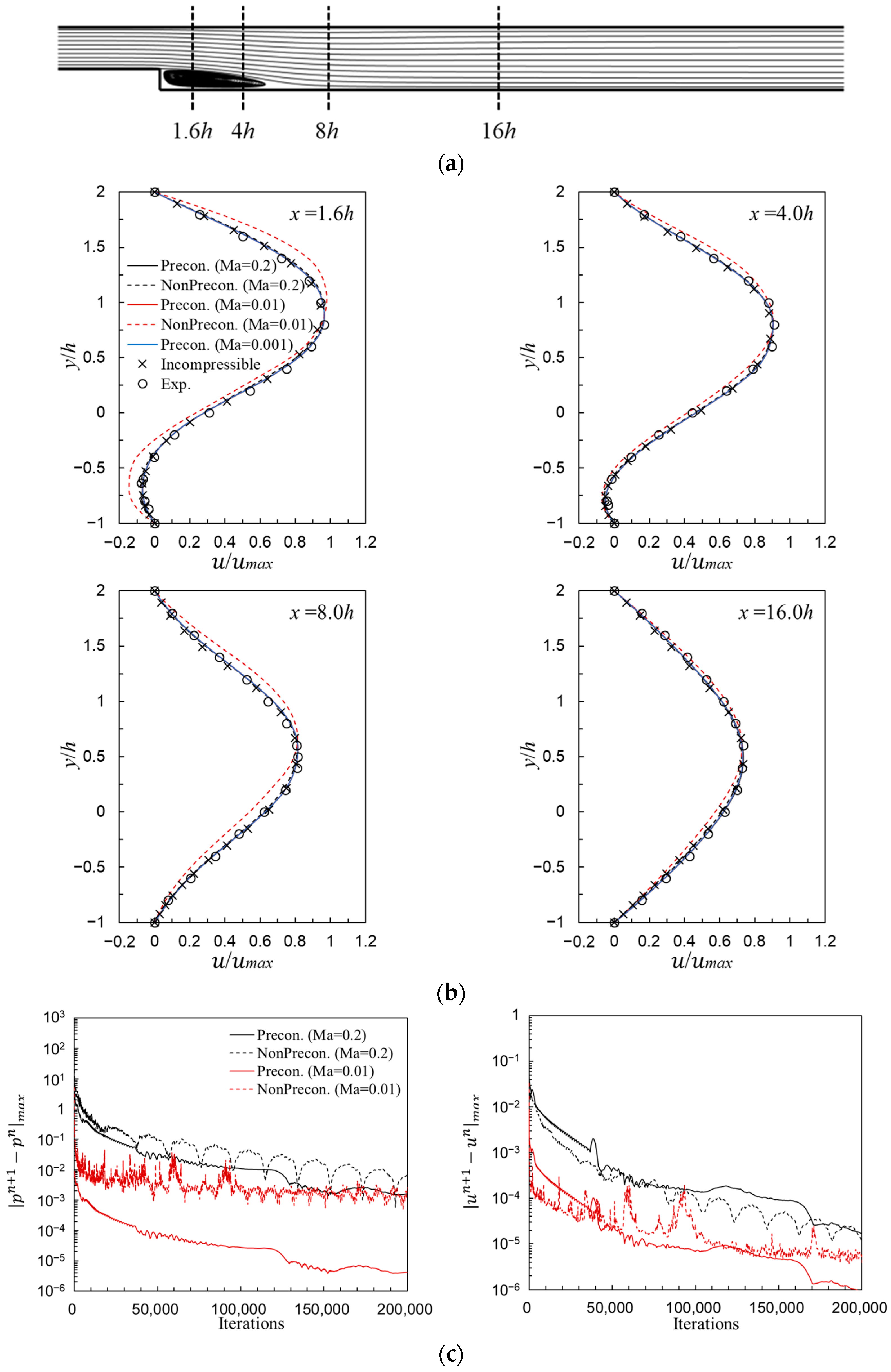
The laminar gas-phase flow at R e = 100 in Case 1 was calculated in the range of inlet Mach number M a = 0.001~0.2 to evaluate the applicability of the present scheme to flows with low Reynolds and low Mach numbers. The computational results of this step channel flow are shown in Figure 3. Figure 3a depicts the monitoring locations of the velocity profiles, and the profiles at these locations are plotted in Figure 3b. The velocity is normalized by the maximum inlet velocity of u m a x . In Figure 3b, we show the streamwise velocity profiles obtained with a non-dimensional time step of 4.2 × 10⁻⁴, except for the non-preconditioned method with M a = 0.01. The results obtained at different Mach numbers overlap indicating that the present preconditioned scheme was successful in simulating a very low Mach number flow up to M a = 0.001 with separation and recirculation. These results agree for all domain regions with experimental data [30] and results obtained by an incompressible flow solver [31]. Flows with M a = 0.2 can be calculated using the compressible flow scheme without preconditioning. However, as the Mach number was reduced to M a = 0.01, the non-preconditioned scheme diverged and failed to compute due to instability. As the time step was decreased by 4.2 × 10⁻⁵, the calculation was successful, but the results show a large discrepancy with the experimental values, as shown in Figure 3b. Moreover, as Mach number was further reduced to 0.001, the calculation without preconditioning was impossible from the start.
Figure 3c shows convergence histories of maximum residuals of pressure | p n + 1 p n | m a x and streamwise velocity | u n + 1 u n | m a x for the calculation in Figure 3b. It is observed that preconditioning the numerical stability terms improves both the convergence rate and numerical stability compared to the case without preconditioning. These improvements are more significant at lower Mach numbers. The present scheme with preconditioned numerical flux is more stable and provides more accurate results than that without preconditioning.

3.3. High Reynolds Number Flow (Cases 2 and 3)

At low Reynolds number flow, we examined the present scheme using the moderately high Reynolds number flows of Cases 2 and 3. The geometries of the flow channel are the same as those of [29], and the Reynolds number range from 61,000 to 128,000. These flows are probably turbulence flows, but at first step, they were calculated without a turbulent model and on a relatively fine grid with 201 × 51 grid points, as there was concern that the inconsistency between the turbulence model and numerical method may lead to uncertainty in identifying the inherent feature of the present scheme.
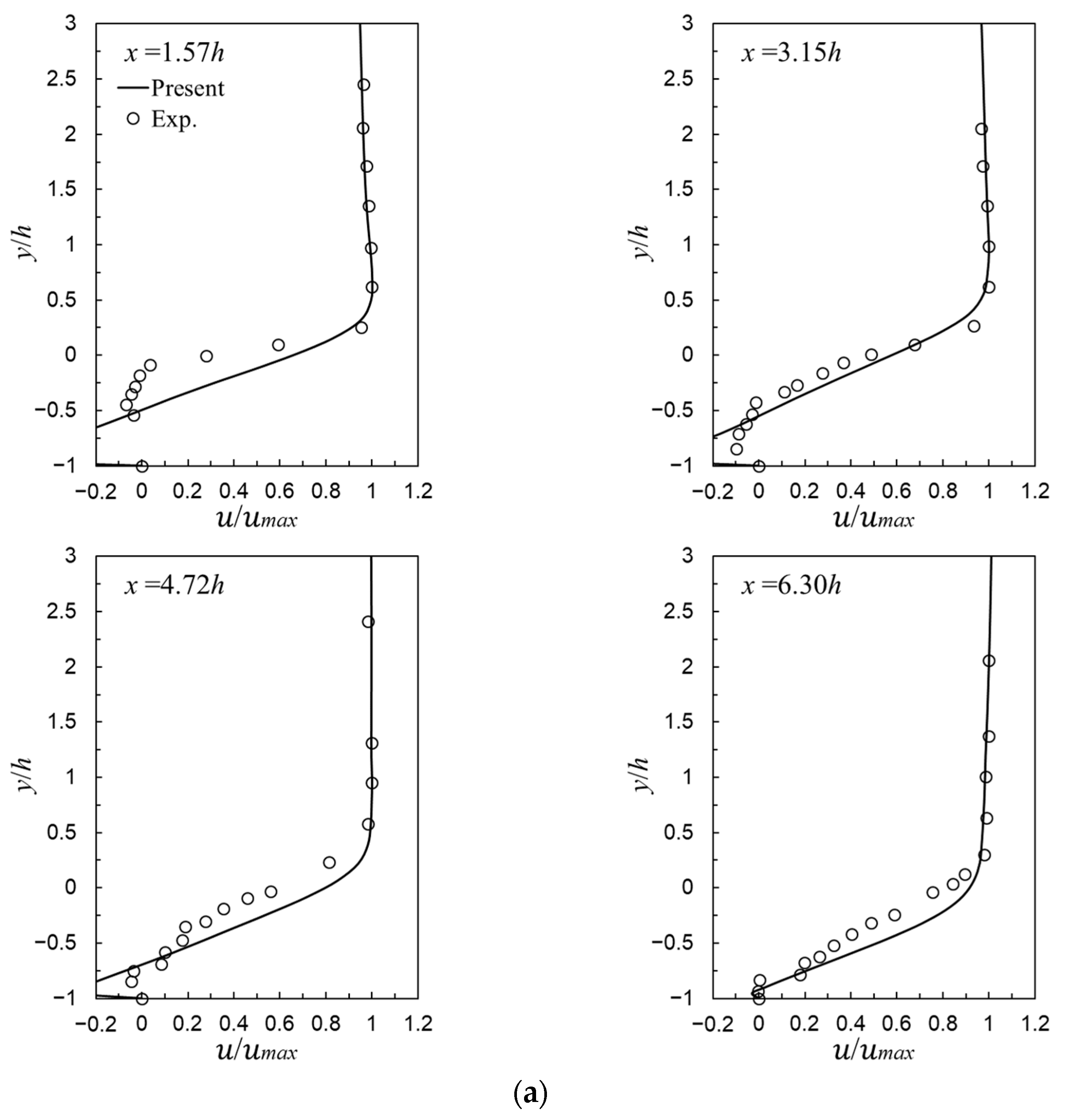
Figure 4 shows streamwise mean velocity profiles for liquid-phase (water) flow observed at several downstream sections of x / h = 0.95~6.30 from the step at R e = 68,000, E R = 1.14 (Figure 4a) and at R e = 61,000, E R = 1.07 (Figure 4b). The velocity profiles were normalized by the maximum velocity of u m a x at the respective sections. Compared with the experimental results [29], the results obtained by the preconditioned scheme show marginal discrepancies in the inner region of the boundary layer, but are fairly well-predicted even at these high Reynolds numbers. In both cases, the length of primary separation behind the step was predicted to be longer than the experimental value, and was longer in Case 2 with the larger expansion ratio. These differences are thought to be due to the difficulty in reproducing the inflow velocity distribution used in the experiments, problems with the turbulence model, and the three-dimensionality of the flow. Therefore, further consideration is needed in actual flow analysis in field applications.
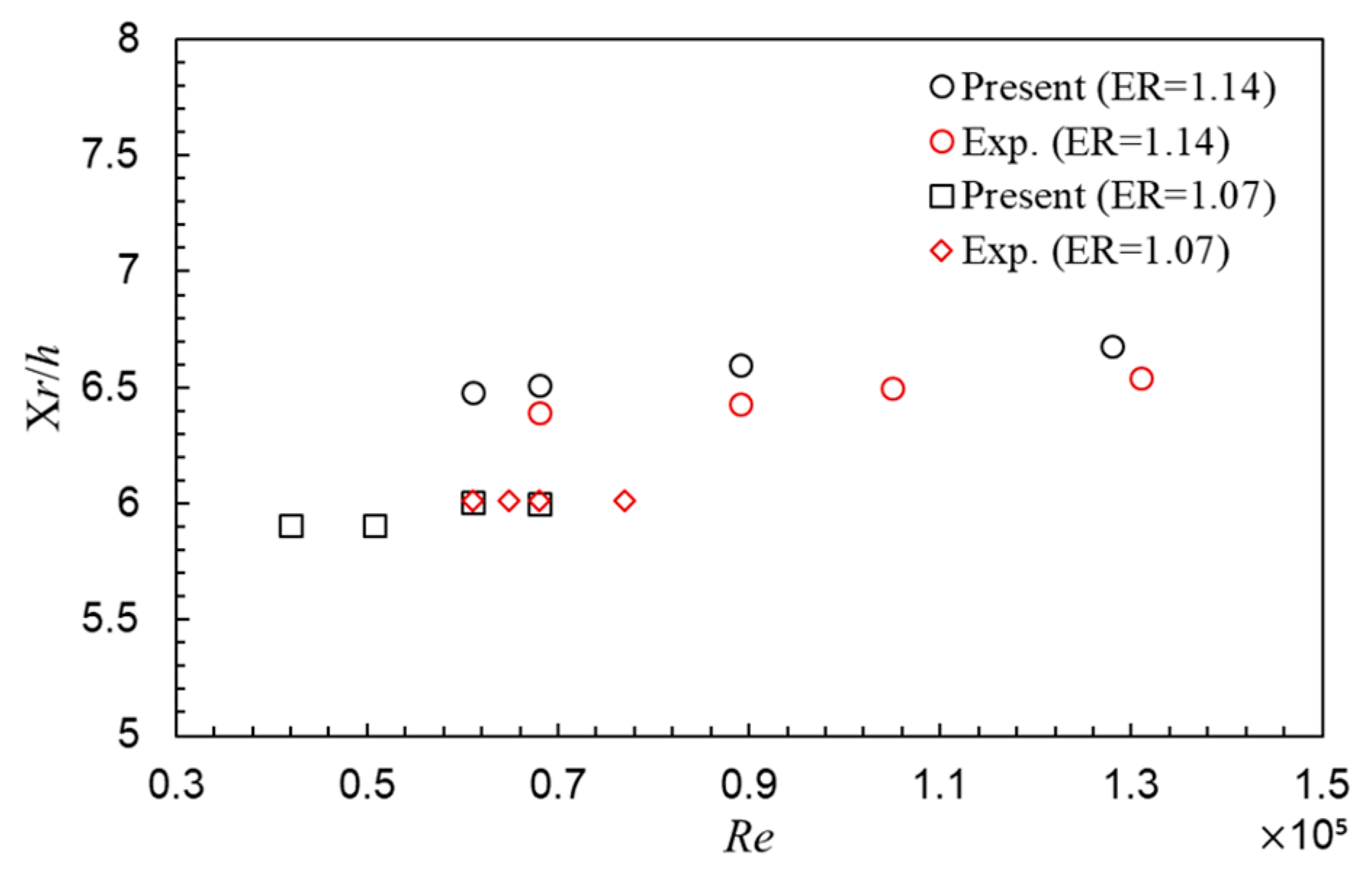
To further validate the applicability of the present scheme, Figure 5 depicts the variation of reattachment length X r . The reattachment length is an important parameter for evaluating the overall performance of the numerical scheme. The present scheme predicts X r very well compared to the experiments. However, the present results are slightly overestimated in E R = 1.14 compared to the experiments [29]. Nonetheless, the tendencies of both are almost the same. It is observed that unlike low Reynolds number flows, the Reynolds number dependence of X r is marginal for high Reynolds number flows in the range tested of this work. That is, in high Reynolds number flows, the effect of R e on X r becomes negligible. Moreover, the present scheme successfully simulates that X r should be short in a stepped channel flow where E R is small [32].

3.4. Gas-Liquid Two-Phase Flows with Cavitation (Case 3)

Finally, the present scheme with preconditioning was applied to a gas-liquid two-phase flow with several cavitation numbers σ , defined by σ = 2 ( p 0 p v ) / ρ 0 U 0 2 , using mean values upstream of the channel and vapor pressure p v . In cavitating flow, the calculations were performed using an isothermal condition because the temperature changes are very small. The initial void fraction of α = 1% was applied, and the two terms S e and S c accounting for the mass transfer effects were neglected.
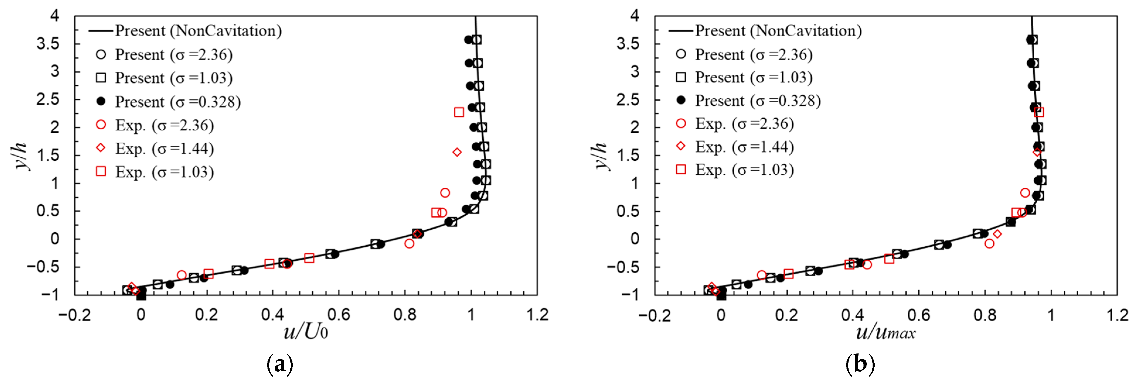
Figure 6 depicts mean streamwise velocity profiles at x = 5.2 h , R e = 64,800, and different cavitation numbers for the channel of E R = 1.07. We show two comparative plots because there is uncertainty in the reference velocity u r e f used for normalization in the experiments. One is the plot normalized by the inlet mean velocity U 0 (Figure 6a), and the other is that normalized by maximum velocity u m a x at the section of x = 5.20 h (Figure 6b). These figures present the velocity distribution changes for different σ in nearly-single-phase flows. In Figure 6a,b, we observe that the comparison between the distributions obtained by the present scheme is similar to that obtained in the experiments by Balachandar [29]. For the tested cavitation numbers σ 1.03, the velocity profiles have little effect on σ , because for this flow, cavitation occurs at approximately at σ < 0.85 [29]. However, in the case of a two-phase flow with cavitation with σ = 0.328 and a maximum void fraction of α = 8%, the velocity distribution outside the boundary layer was predicted to be slightly slower.
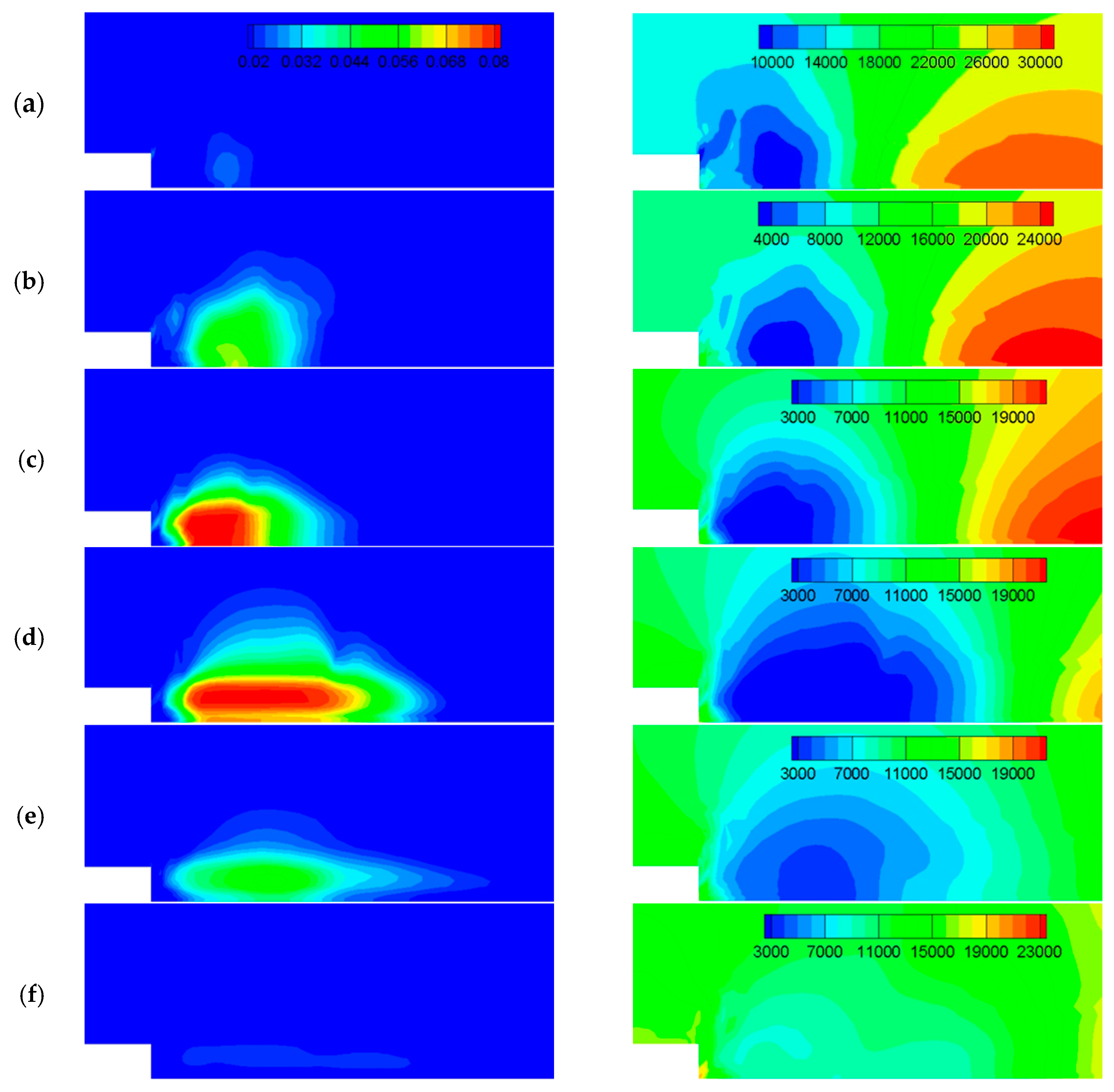
Figure 7 depicts a time series of instantaneous void fraction and pressure distribution for the cavitating flow with σ = 0.328 examined in Figure 6. The illustrations show that the development and shedding process of vortex cavitation occur near the recirculation region behind step. The vortex cavitation formed in the center of the primary vortex (Figure 7a) grows with decreasing pressure (Figure 7b,c). Once the cavity reaches its maximum length and thickness (Figure 7d), the cavitation begins to decay and shed due to the re-entrant liquid flow from the rear of the cavity and the recovery of pressure (Figure 7e), and eventually disappears (Figure 7f). After that, the shedding cycle starts again quasiperiodically. This cavitating flow pattern is similar to that observed in experiments [33], and it facilitates understand the void fraction and pressure distributions inside the cavity.
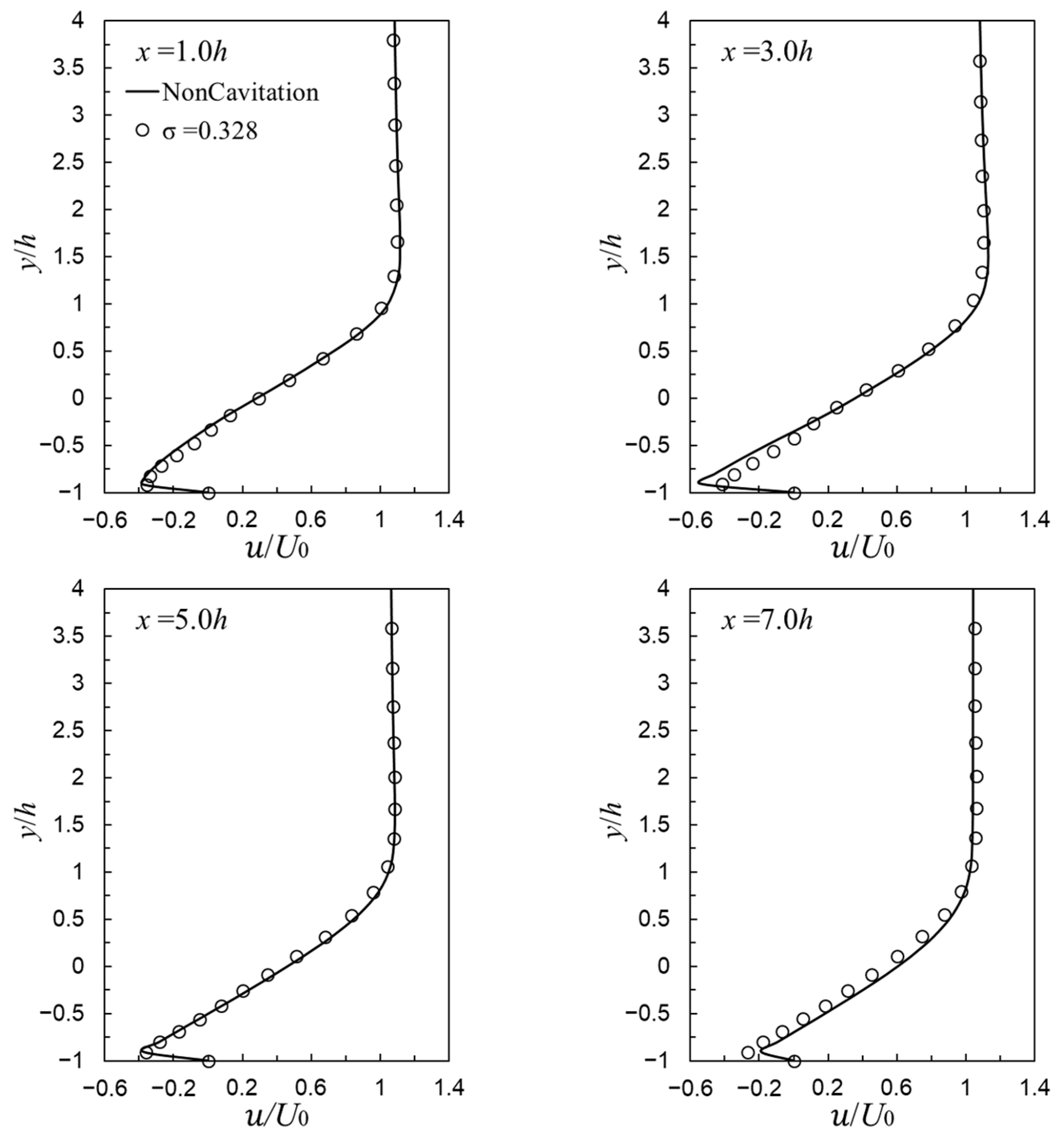
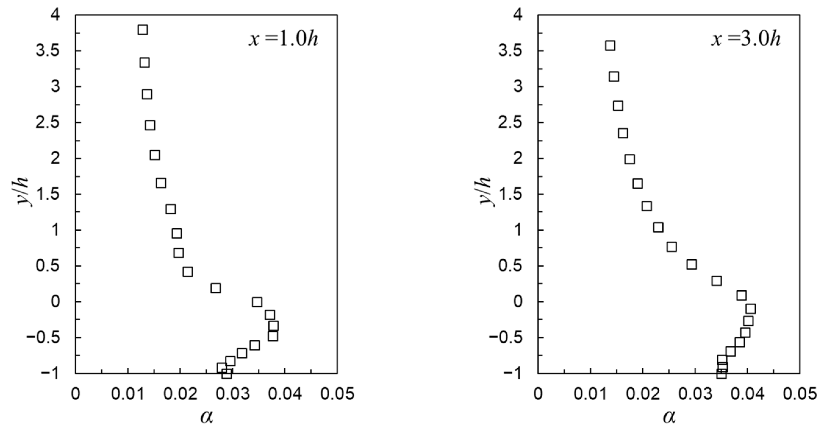
For this cavitating flow, Figure 8 and Figure 9 show the time-averaged streamwise velocity and void fraction distributions for one period of Figure 7 at several streamwise sections around the primary vortex. From Figure 8, it is observed that in this shedding cycle, as cavitation occurs, near the reattachment point, the thickness of the separation bubble slightly increases compared to the case without cavitation, and the reattachment length is also expected to be higher. While the reverse velocities near the step within the recirculation region are somewhat slower than those without cavitation. Furthermore, from Figure 9, we can confirm the average spatial distribution of cavities shown in Figure 7 as well as their magnitude, length, and thickness. As observed above, the present scheme successfully simulated the unsteady phenomena of the formation, development, and shedding of the cavitation.
Figure 10 shows another computational result of void fraction and pressure distributions at R e = 31,000 and σ = 1.420 for E R = 1.07 channel. In this computation, the initial void fraction α of 10% was applied, which is significantly larger than the dissolved air content of the tap water used in the water tunnel experiments (approximately 2% at 15 °C [34]). The flow velocity was controlled to avoid unnatural shock waves in the experiments due to the influence of the initial void fraction. A process in which the gaseous cavitation generated in the low-pressure region near the center of the primary vortex behind the step grows and sheds is similar to that shown in Figure 7. However, the scale of the cavitation is smaller since σ is larger [17]. It was confirmed that the present scheme can stably simulate gas-liquid two-phase flows with cavitation even with a relatively large initial void fraction.

4. Conclusions

To analyze unsteady gas-liquid multiphase flows, a time-consistent upwind difference scheme was presented and applied to 2-D flow problems through a backward-facing step channel. In this study, the governing equations were derived in general curvilinear coordinates to apply to a variety of flow fields. To maintain time consistency for unsteady problems and enhance the numerical stability in calculations of gas-liquid flows with incompressible and compressible flow properties, the fundamental equations were preconditioned only in the numerical dissipative terms without modifying the time derivative terms. Therefore, the proposed scheme provides a time-consistent solution compared with conventional preconditioning methods. Furthermore, the fundamental equations with the primitive unknown variables were time integrated without introducing any pseudo-time steps, so that the present scheme can reduce computing time compared with the dual time-step method and improve simulations of the behavior of gas-liquid multiphase flows with the incompressible flow characteristics. The governing equations were solved using a third-order explicit Runge-Kutta method and the flux difference splitting finite-difference scheme combined with a third-order MUSCL TVD scheme.
Through numerical experiments for various 2-D single-phase and gas-liquid two-phase flows with different flow conditions, including cavitation numbers, the acceptability and capability of the present scheme were demonstrated. In particular, the present scheme was successfully applied to flows with very low Mach numbers of 0.001 and two-phase flows with different cavitation numbers. It was also confirmed that the preconditioned stability term significantly improves the convergence rate and numerical stability of steady and unsteady flow computations. Furthermore, the effectiveness and applicability of the present scheme in calculating unsteady gas-liquid multiphase flows was observed through numerical simulations of unsteady cavitating flows at high Reynolds numbers.
Since engineering problems often fall within the turbulent regime, future research is need to accurately estimate the effects of turbulence. Moreover, further validation of the scheme is also required so that the scheme can be applied to multiphase flow models such as phase change and boiling models.

Author Contributions

Conceptualization, methodology, B.S.; validation, investigation, T.Z. and B.S.; writing—original draft preparation, writing—review and editing, T.Z. and B.S.; visualization, T.Z.; supervision, B.S. All authors have read and agreed to the published version of the manuscript.

Funding

This research received no external funding.

Data Availability Statement

Some data in the manuscript will be made available through request to the corresponding author.

Acknowledgments

This work was partly supported by JSPS KAKENHI Grant Numbers JP20K04288 and JP23K03662.

Conflicts of Interest

The authors declare no conflicts of interest.

References

  1. Unverdi, S.O.; Tryggvason, G. A Front-tracking Method for Viscous, Incompressible, Multi-Fluid Flows. J. Comput. Phys. 1992, 100, 25–37. [Google Scholar] [CrossRef]
  2. Nomura, T. ALE Finite Element Computations of Fluid-Structure Interaction Problems. Comput. Methods Appl. Mech. Eng. 1994, 112, 291–308. [Google Scholar] [CrossRef]
  3. Hirt, C.W.; Nichols, B.D. Volume of Fluid (VOF) Method for the Dynamics of Free Boundaries. J. Comput. Phys. 1981, 39, 201–225. [Google Scholar] [CrossRef]
  4. Tomiyama, A.; Sou, A.; Minagawa, H.; Sakaguchi, T. Numerical Analysis of a Single Bubble with VOF Method. Trans. JSME Ser. B 1991, 57, 2167–2173. [Google Scholar] [CrossRef]
  5. Ito, K.; Kunugi, T.; Ezure, T.; Tanaka, M.; Ito, D.; Saito, Y. An Improved Pressure Calculation Method for Simulations of Gas–Liquid Two-Phase Flows on Unstructured Meshes. Multiph. Sci. Technol. 2019, 31, 109–131. [Google Scholar] [CrossRef]
  6. Sussman, M.; Smereka, P.; Osher, S. A Level Set Approach for Computing Solutions to Incompressible Two-Phase Flow. J. Comput. Phys. 1994, 114, 146–159. [Google Scholar] [CrossRef]
  7. Turkel, E. Preconditioned Methods for Solving the Incompressible and Low Speed Compressible Equations. NASA LRC Contractor Report, NASA CR-178086; 1986. Available online: https://ntrs.nasa.gov/citations/19860016597 (accessed on 29 January 2025).
  8. Merkle, C.L.; Feng, J.Z.; Buelow, P.E.O. Computational Modelling of the Dynamics of Sheet Cavitation. In Proceedings of the 3rd International Symposium on Cavitation, Grenoble, France, 7–l0 April 1998. [Google Scholar]
  9. Edwards, J.R.; Liou, M.-S. Low-diffusion Flux-splitting Methods for Flows at All Speeds. In Proceedings of the 13th Computational Fluid Dynamics Conference, Snowmass Village, CO, USA, 29 June–2 July 1997. [Google Scholar] [CrossRef]
  10. Seo, J.H.; Moon, Y.J.; Shin, B.R. Prediction of Cavitation Flow Noise by Direct Numerical Simulation. J. Comput. Phys. 2008, 227, 6511–6531. [Google Scholar] [CrossRef]
  11. Dittakavi, N.; Chunekar, A.; Frankel, S. Large Eddy Simulation of Turbulent-cavitation Interactions in a Venturi Nozzle. ASME J. Fluids Eng. 2010, 132, 121301-1–121301-11. [Google Scholar] [CrossRef]
  12. Shuen, J.S.; Chen, K.H.; Choi, Y.H. A Time-accurate Algorithm for Chemical Non-equilibrium Viscous Flows at All Speeds. In Proceedings of the 28th Joint Propulsion Conference and Exhibit, Nashville, TN, USA, 6–8 July 1992. [Google Scholar] [CrossRef]
  13. Weiss, J.M.; Smith, W.A. Preconditioning Applied to Variable and Constant Density Flows. In Proceedings of the 25th AIAA Fluid Dynamics Conference, Colorado Springs, CO, USA, 20–23 June 1994. [Google Scholar] [CrossRef]
  14. Venkateswaran, S.; Merkle, L. Dual Time Stepping and Preconditioning for Unsteady Computations. In Proceedings of the 33rd AIAA Aerospace Sciences Meeting, Reno, NV, USA, 9–12 January 1995. [Google Scholar] [CrossRef]
  15. Shin, B.R.; Yamamoto, S.; Yuan, X. Application of Preconditioning Method to Gas–liquid Two-phase Flow Computations. ASME J. Fluids Eng. 2004, 126, 605–612. [Google Scholar] [CrossRef]
  16. Zhao, T.; Shin, B.R. Upwind Scheme Using Preconditioned Artificial Dissipation for Unsteady Gas–liquid Two-phase Flow and Its Application to Shock Tube Flow. J. Appl. Fluid Mech. 2024, 17, 1806–1819. [Google Scholar] [CrossRef]
  17. Shin, B.R.; Iwata, Y.; Ikohagi, T. A Numerical Study of Unsteady Cavitating Flows Using a Homogenous Equilibrium Model. Comput. Mech. 2003, 30, 388–395. [Google Scholar] [CrossRef]
  18. Chorin, A.J. A Numerical Method for Solving Incompressible Viscous Flow Problems. J. Comput. Phys. 1967, 2, 12–26. [Google Scholar] [CrossRef]
  19. Kwak, D.; Chang, J.L.C.; Shanks, S.P.; Chakravarty, S.R. A three dimensional Incompressible Navier-Stokes Flow Solver Using Primitive Variables. In Proceedings of the 22nd AIAA Aerospace Sciences Meeting, Reno, NV, USA, 9–12 January 1984. [Google Scholar] [CrossRef]
  20. Choi, Y.H.; Merkle, C.L. The Application of Preconditioning in Viscous Flows. J. Comput. Phys. 1993, 105, 207–223. [Google Scholar] [CrossRef]
  21. Yoo, Y.-L.; Kim, J.-C.; Sung, H.-G. Homogeneous Mixture Model Simulation of Compressible Multi-phase Flows at All Mach Number. Int. J. Multiph. Flow 2021, 143, 103745. [Google Scholar] [CrossRef]
  22. Roe, P.L. Approximate Riemann Solvers, Parameter Vectors, and Difference Scheme. J. Comput. Phys. 1981, 43, 357–372. [Google Scholar] [CrossRef]
  23. van Leer, B. Towards the Ultimate Conservative Difference Scheme (v) A Second-order Sequel to Godunov’s Method. J. Comput. Phys. 1979, 32, 101–136. [Google Scholar] [CrossRef]
  24. Shin, B.R. Stable Numerical Method Applying a Total Variation Diminishing Scheme for Incompressible Flow. AIAA J. 2003, 41, 49–55. [Google Scholar] [CrossRef]
  25. Turkel, E.; Fiterman, A.; van Leer, B. Preconditioning and the Limit of the Compressible to the Incompressible Flow Equations for Finite Difference Schemes. In Frontiers of Computational Fluid Dynamics 1994; Caughey, D.A., Hafez, M.M., Eds.; John Wiley and Sons: Chichester, NY, USA, 1995; pp. 215–234. [Google Scholar]
  26. Liou, M.-S.; Edwards, J.R. Numerical Speed of Sound and its Application to Schemes for All Speeds. In Proceedings of the 14th AIAA Computational Fluid Dynamics Conference, Norfolk, VA, USA, 1–5 November 1999. [Google Scholar] [CrossRef]
  27. Morgan, K.; Jaques, P.; François, T. Analysis of Laminar Flow Over a Backward Facing Step, Notes on Numerical Fluid Mechanics; Vieweg + Teubner Verlag: Wiesbaden, Germany, 1984; Volume 9, pp. 245–267. [Google Scholar] [CrossRef]
  28. Kim, J.; Kline, S.J.; Johnston, J.P. Investigation of a Reattaching Turbulent Shear Layer: Flow Over a Backward-facing Step. J. Fluids Eng. 1980, 102, 302–308. [Google Scholar] [CrossRef]
  29. Balachandar, R. Characteristics of Separated Flows Including Cavitation Effects. Ph.D. Thesis, Concordia University, Montreal, Canada, March 1990. [Google Scholar]
  30. Kueny, J.L.; Binder, G. Viscous Flow over Backward Facing Steps an Experimental Investigation. In Analysis of Laminar Flow over a Backward Facing Step, Notes on Numerical Fluid Mechanics; Morgan, K., Periaux, J., Thomasset, F., Eds.; Vieweg+Teubner Verlag: Wiesbaden, German, 1984; Volume 9, pp. 32–47. [Google Scholar] [CrossRef]
  31. Shin, B.R.; Ikohagi, T.; Daiguji, H. An Unsteady Implicit SMAC Scheme for Two-Dimensional Incompressible Navier-Stokes Equations. Trans. JSME Ser. B 1993, 36, 598–606. [Google Scholar] [CrossRef]
  32. Eaton, J.K.; Johnston, J.P. A Review of Research on Subsonic Turbulent Flow Reattachment. AIAA J. 1981, 19, 1093–1100. [Google Scholar] [CrossRef]
  33. Bhatt, A. Unsteady Cavitation in Separating and Re-attaching Shear Flows. Ph.D. Thesis, University of Michigan, Ann Arbor, MI, USA, January 2021. [Google Scholar]
  34. Numachi, F. Über die Kavitationsentstehung mit besonderem Bezug auf den Luftgehalt des Wassers. Ing. Arch. 1936, 7, 396–409. [Google Scholar] [CrossRef]
Figure 1. Schematic of backward-facing step flow.
Fluids 10 00038 g001
Figure 2. Computation grid of backward-facing step flow for E R = 1.14.
Fluids 10 00038 g002
Figure 3. Computational results of a backward-facing step channel for gas phase flow at R e = 100, and E R = 1.5: (a) Streamline and cross-sections for measurement; (b) Streamwise velocity profiles at several Mach numbers; (c) Convergence histories.
Fluids 10 00038 g003
Figure 4. Comparison of streamwise velocity profiles in a backward-facing step channel for liquid phase flow: (a) Streamwise velocity profiles at R e = 68,000, E R = 1.14; (b) Streamwise velocity profiles at R e = 61,000, E R = 1.07.
Fluids 10 00038 g004aFluids 10 00038 g004b
Figure 5. Variation of reattachment length with Reynolds number and expansion ratio.
Fluids 10 00038 g005
Figure 6. Streamwise velocity distributions at x = 5.20 h for R e = 64,800, E R = 1.07, and different cavitation numbers: (a) Velocity profiles normalized by the inlet mean velocity U 0 ; (b) Velocity profiles normalized by the maximum velocity u m a x at x = 5.20 h .
Fluids 10 00038 g006
Figure 7. Time evolution of void fraction (left) and pressure (right) distribution at R e = 64,800, σ = 0.328, and initial α = 1% for E R = 1.07 channel. (a) T 0 ms. (b) T 0 + 10 ms. (c) T 0 + 20 ms. (d) T 0 + 50 ms. (e) T 0 + 70 ms. (f) T 0 + 80 ms.
Fluids 10 00038 g007
Figure 8. Computational results of mean streamwise velocity distributions at different streamwise sections at R e = 64,800, σ = 0.328, and initial α = 1% for E R = 1.07 channel.
Fluids 10 00038 g008
Figure 9. Computational results of mean void fraction distributions at different streamwise sections at R e = 64,800, σ = 0.328, and initial α = 1% for E R = 1.07 channel.
Fluids 10 00038 g009aFluids 10 00038 g009b
Figure 10. Time evolution of void fraction (left) and pressure (right) distribution at R e = 31,000, σ = 1.420, and initial α = 10% for E R = 1.07 channel. (a) T 0 ms. (b) T 0 + 30 ms. (c) T 0 + 60 ms. (d) T 0 + 160 ms. (e) T 0 + 220 ms. (f) T 0 + 260 ms.
Fluids 10 00038 g010
Table 1. Computational conditions of backward-facing step channel.
CaseExpansion
Ratio
Inlet
Length
Outlet
Length
Reynolds
Number
Grid Points
E R L 1 L 2 R e
11.5 9 h 48 h 10090 × 21
21.14 10 h 100 h 61,000~128,000201 × 51
31.07 20 h 200 h 31,000~77,000201 × 51
Disclaimer/Publisher’s Note: The statements, opinions and data contained in all publications are solely those of the individual author(s) and contributor(s) and not of MDPI and/or the editor(s). MDPI and/or the editor(s) disclaim responsibility for any injury to people or property resulting from any ideas, methods, instructions or products referred to in the content.