Article

Transonic Aerodynamic Performance Analysis of a CRM Joined-Wing Configuration †

School of Engineering, University of the West of England, Bristol BS16 1QY, UK
*
Author to whom correspondence should be addressed.
This paper is an extended version of our paper published in Hanman, P.; Yao, Y.; Bouferrouk, A. Aerodynamics of a CRM Joined-Wing Configuration at Transonic Speeds. In Proceedings of the 57th 3AF International Conference on Applied Aerodynamics, Bordeaux, France, 29–31 March 2023.
Fluids 2025, 10(2), 27; https://doi.org/10.3390/fluids10020027

Submission received: 6 November 2024 / Revised: 10 January 2025 / Accepted: 23 January 2025 / Published: 25 January 2025
(This article belongs to the Special Issue Drag Reduction in Turbulent Flows, 2nd Edition)

Abstract

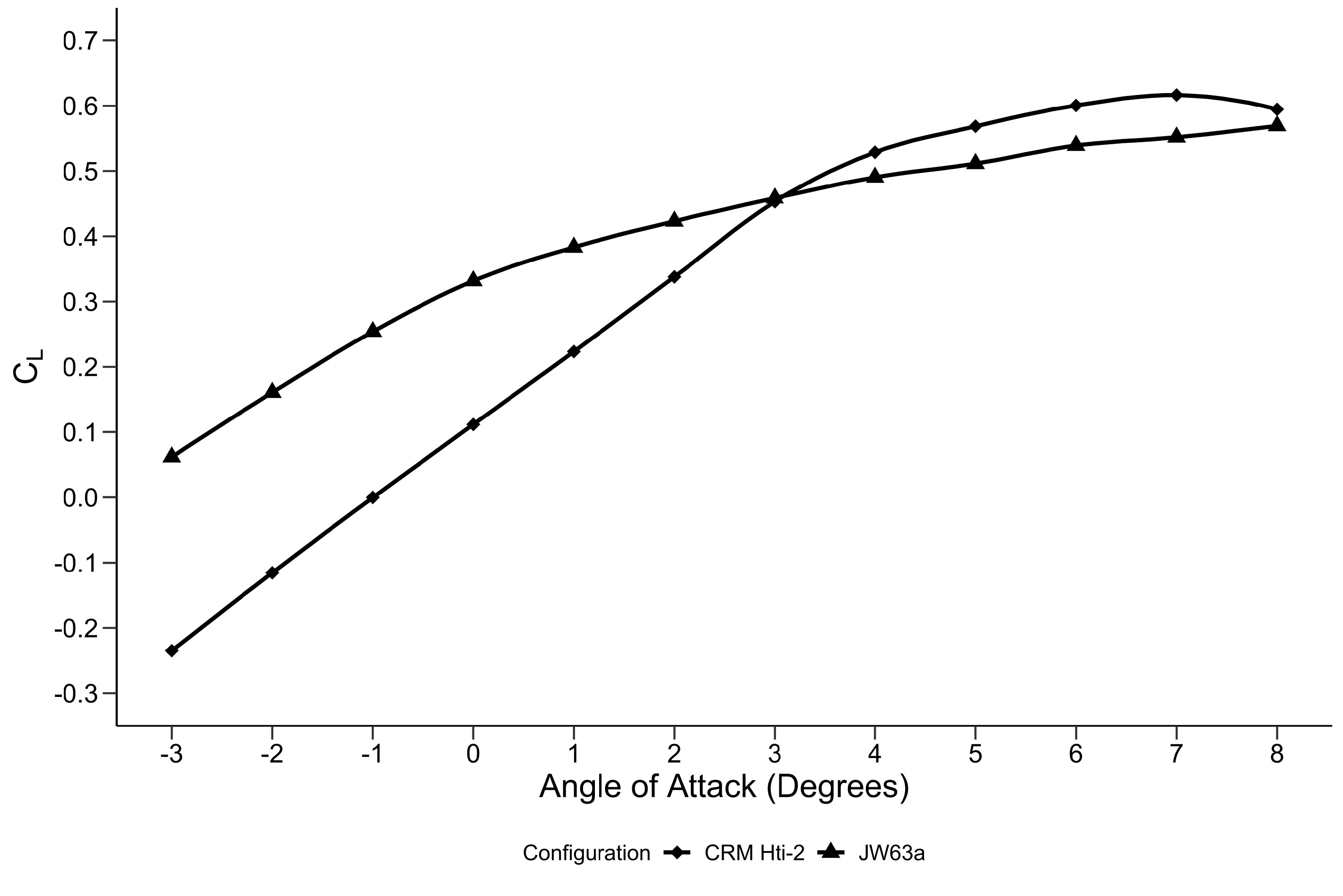
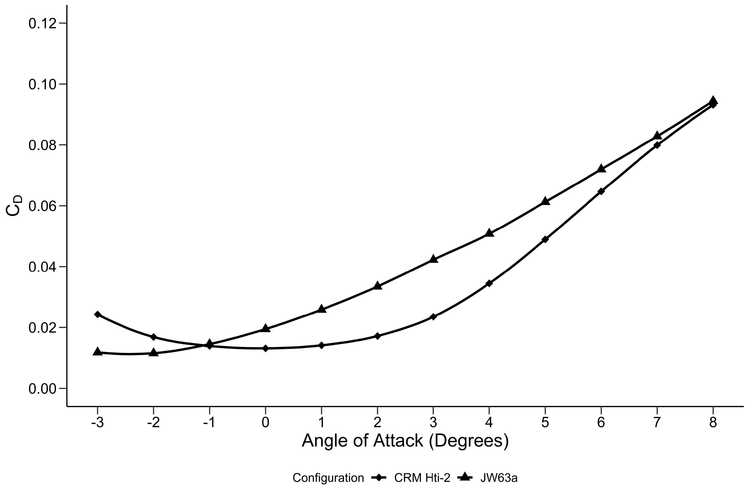
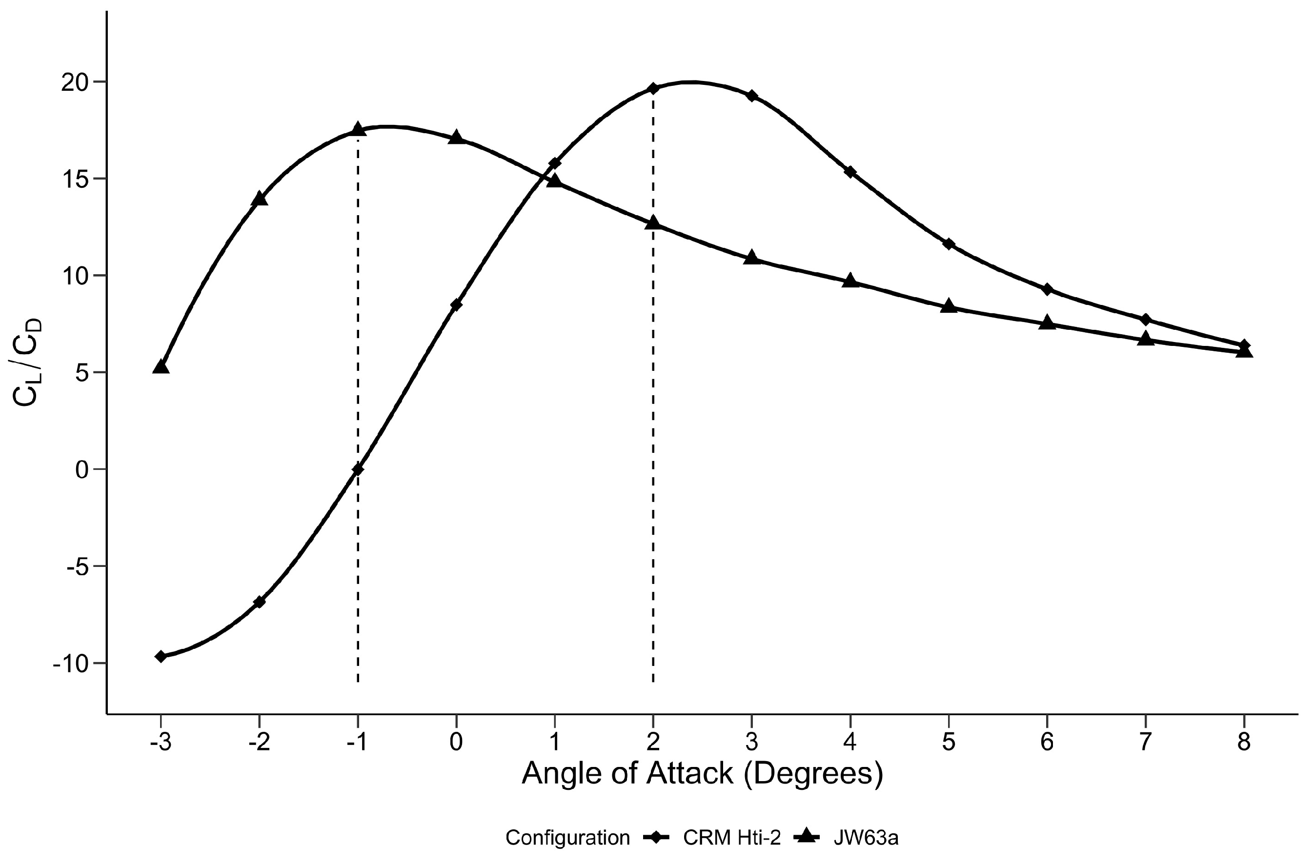
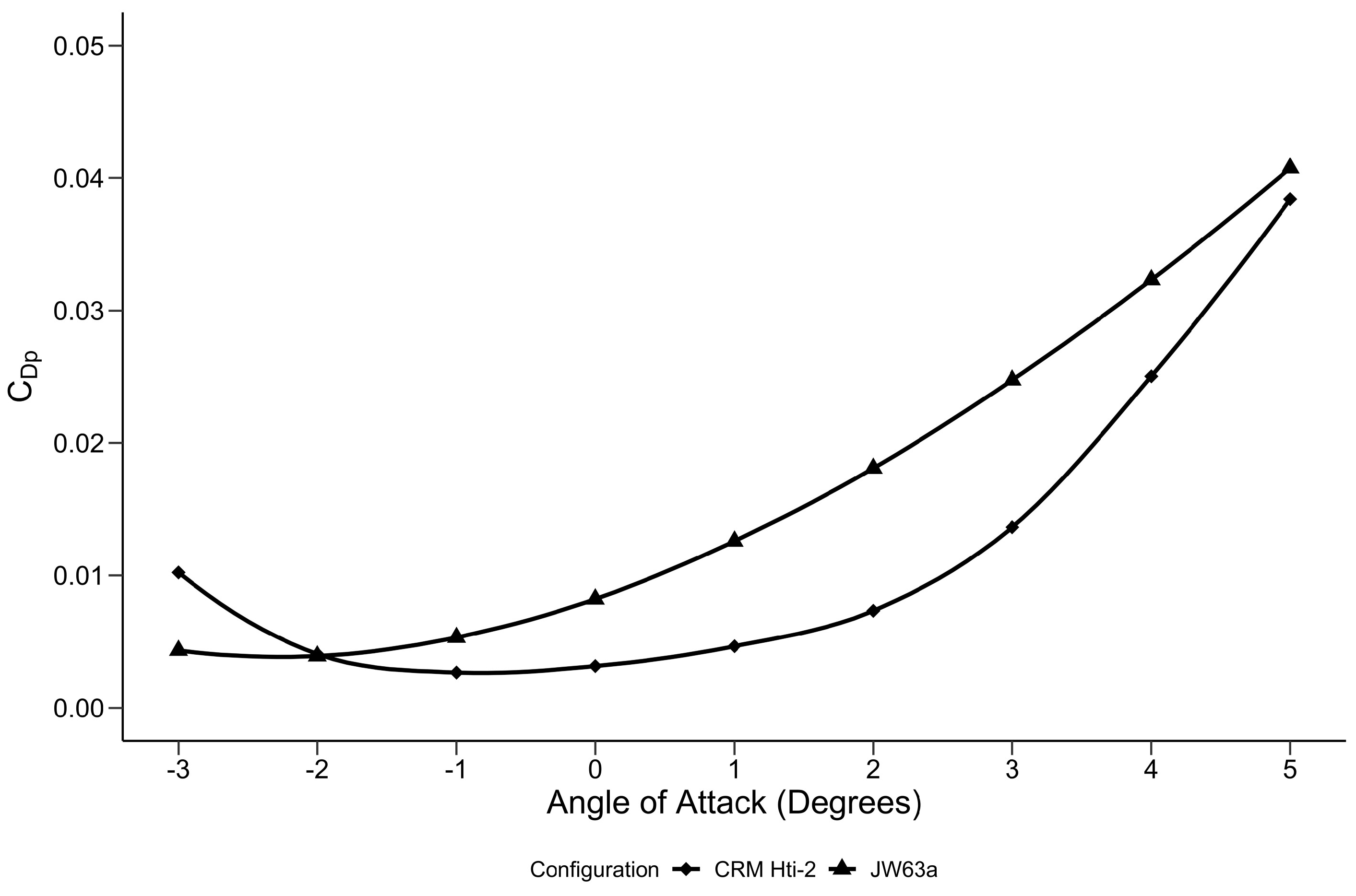
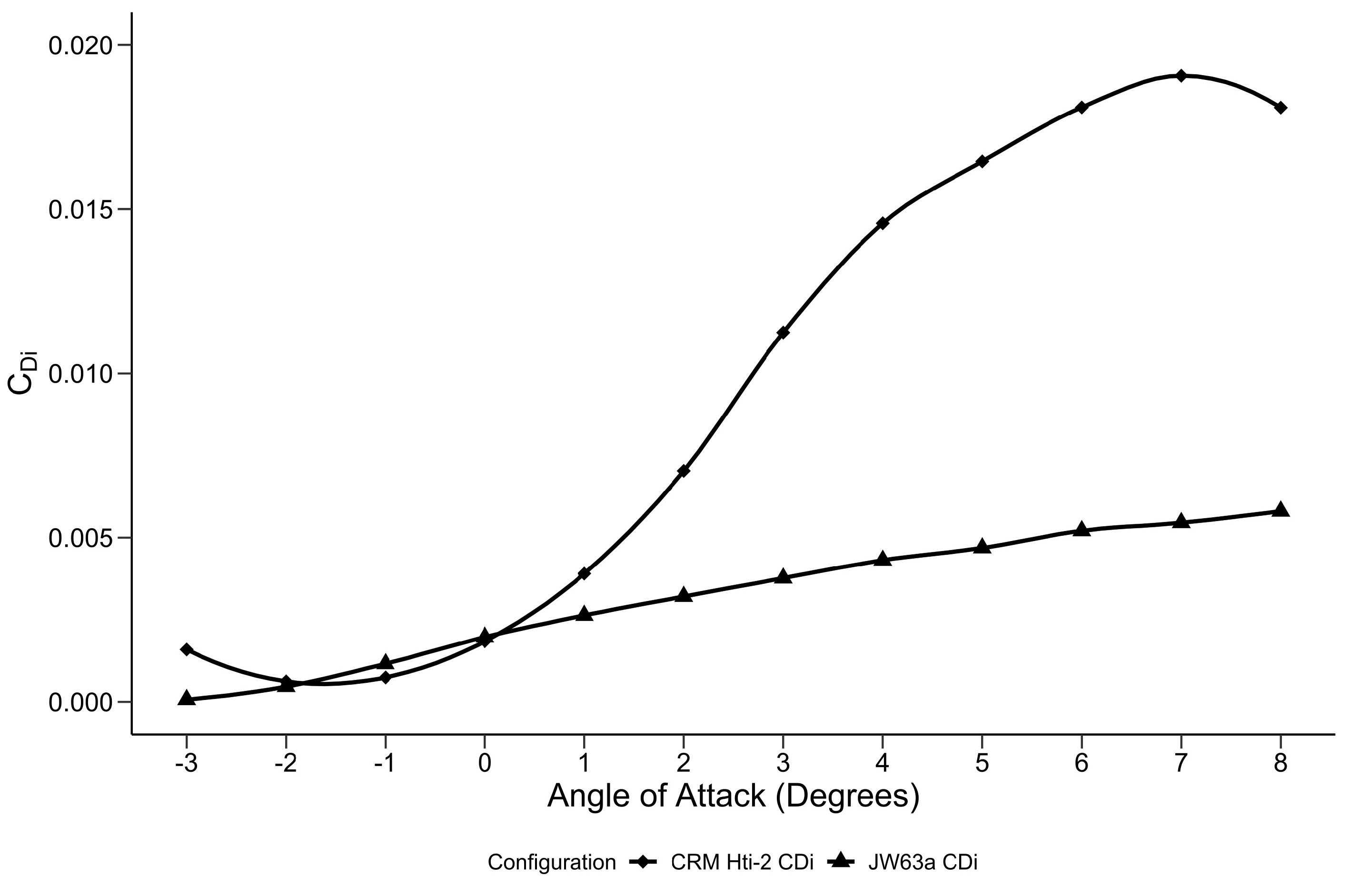
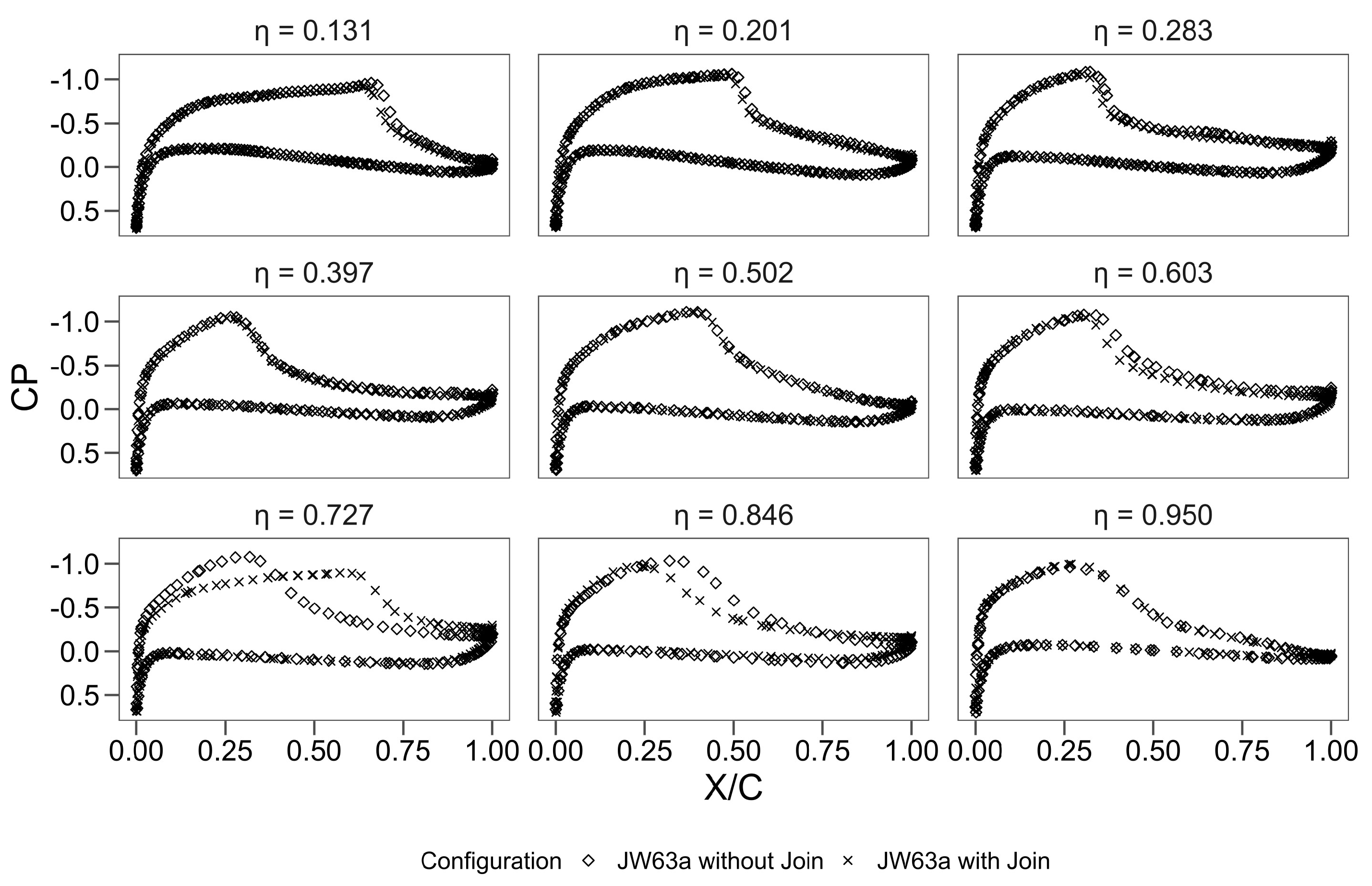
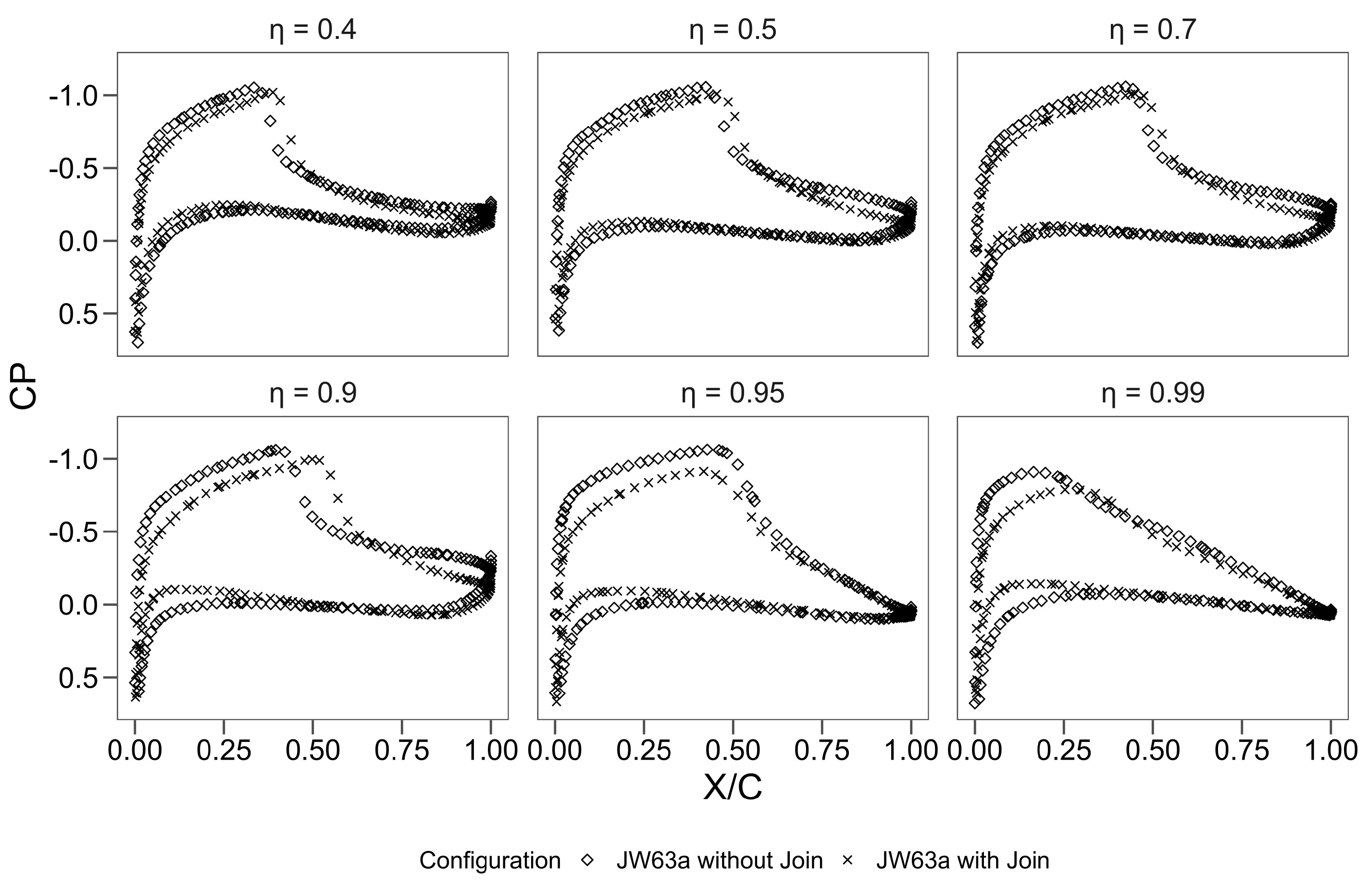
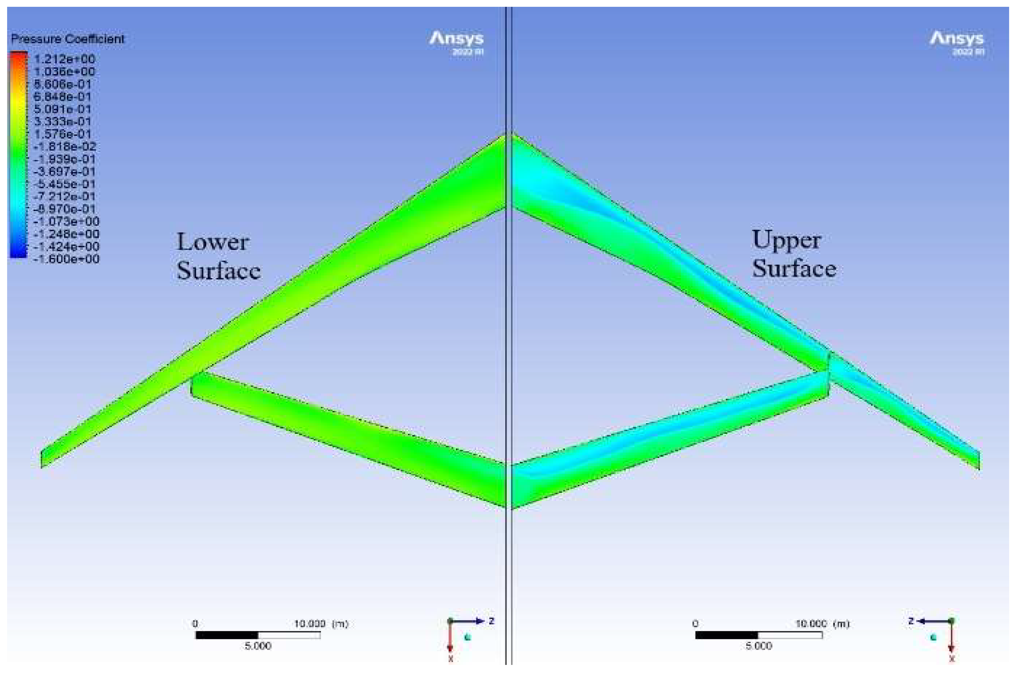
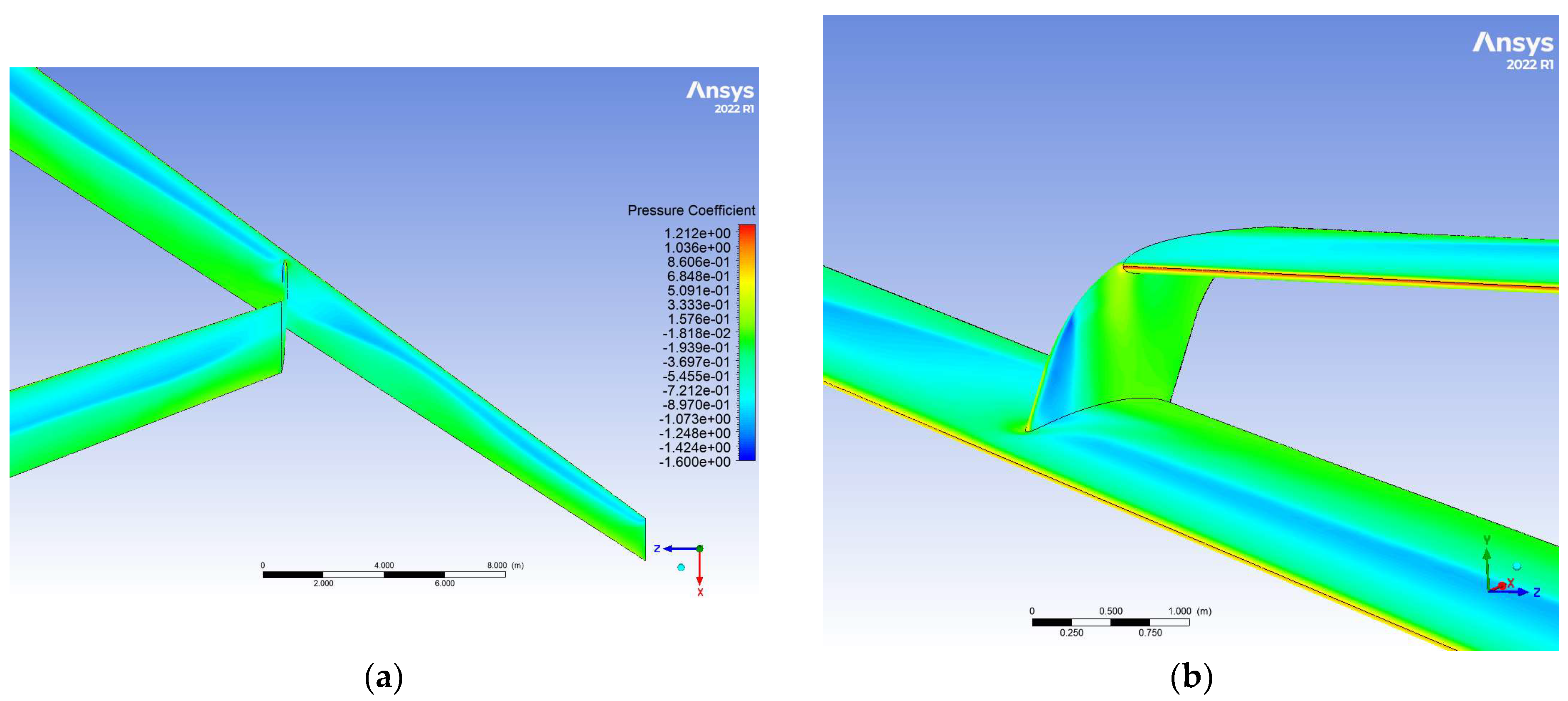
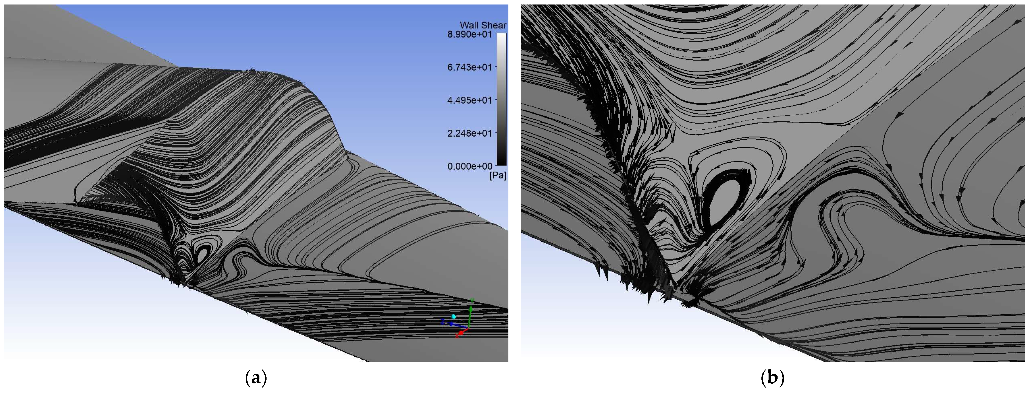
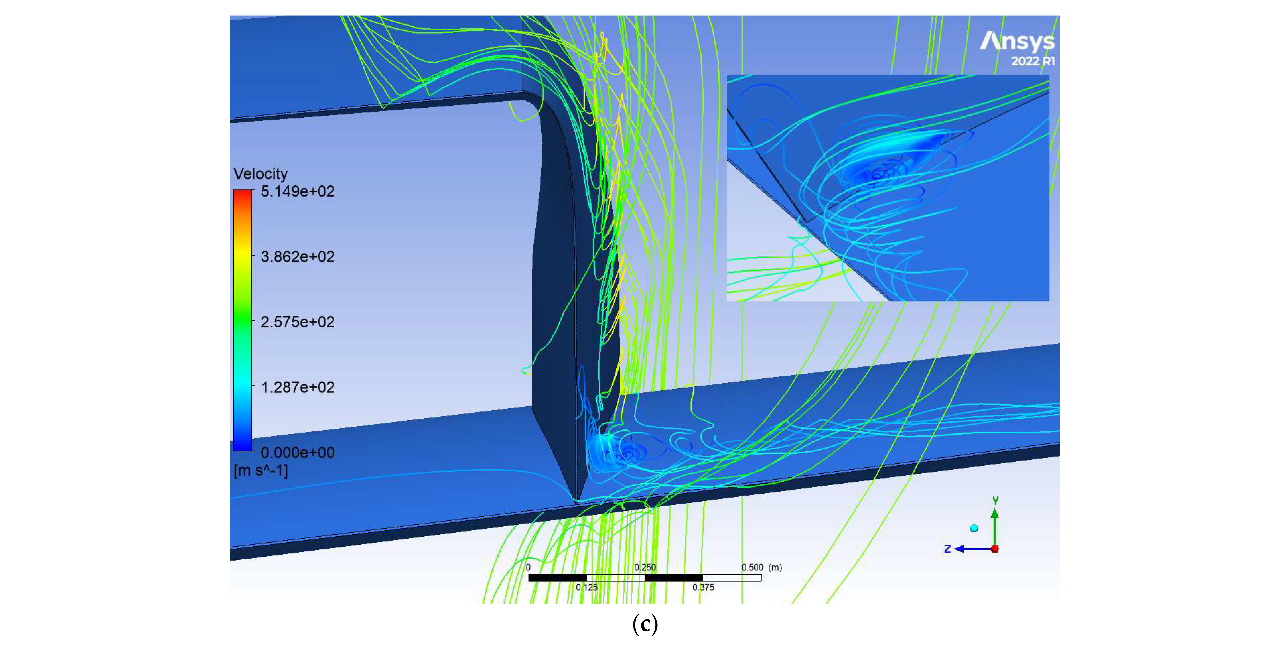
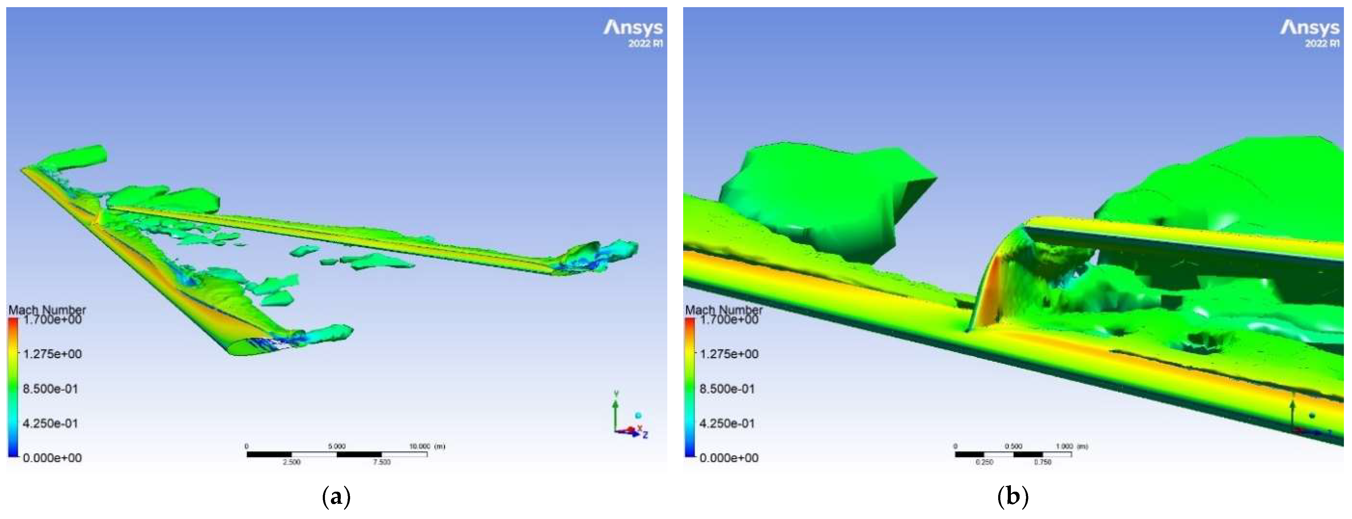
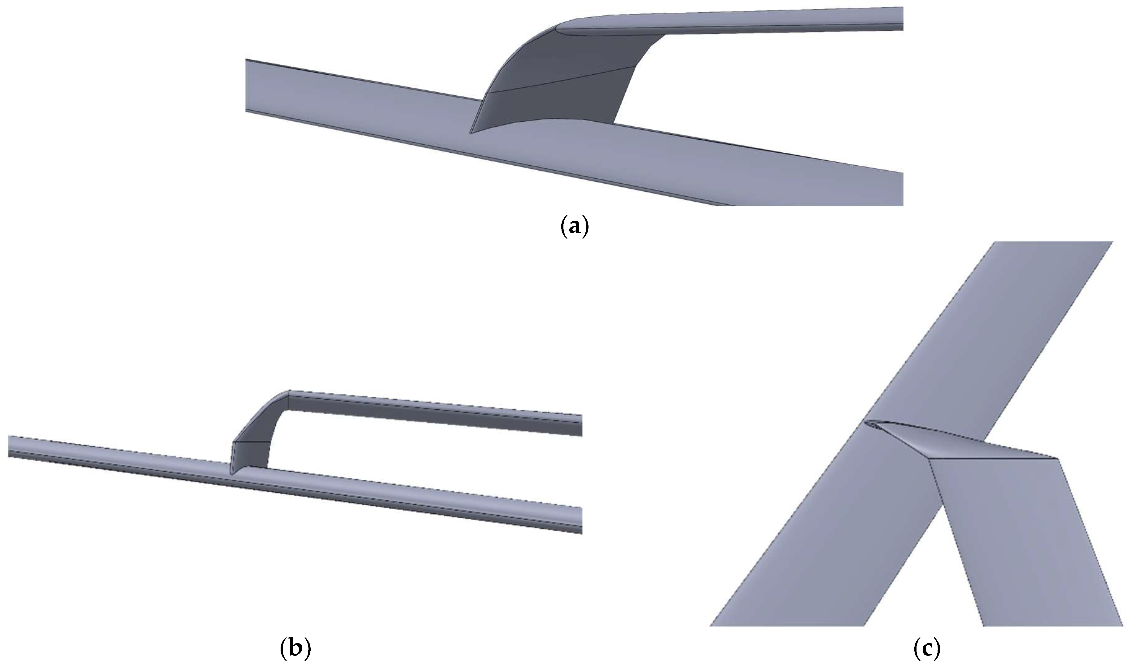
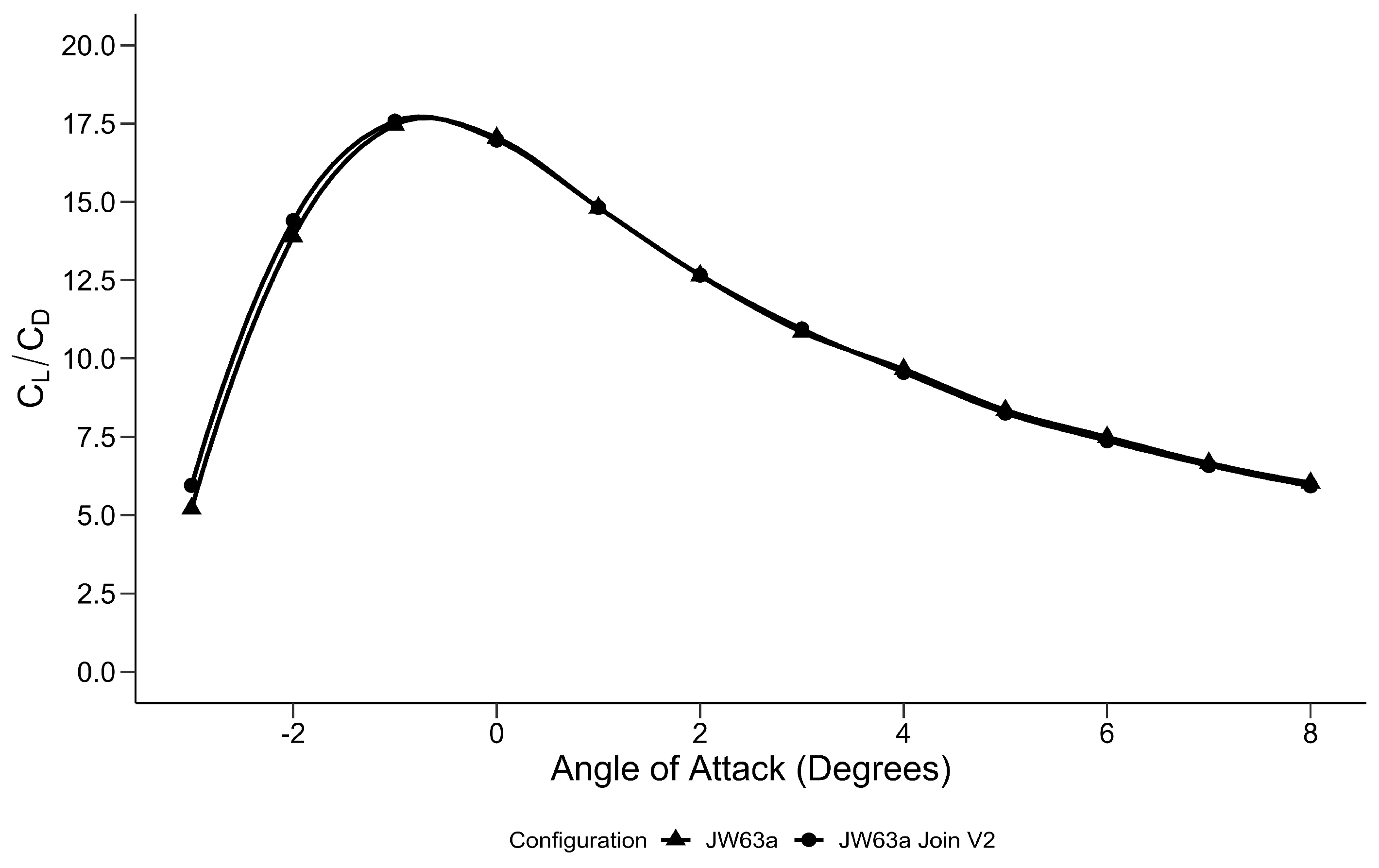
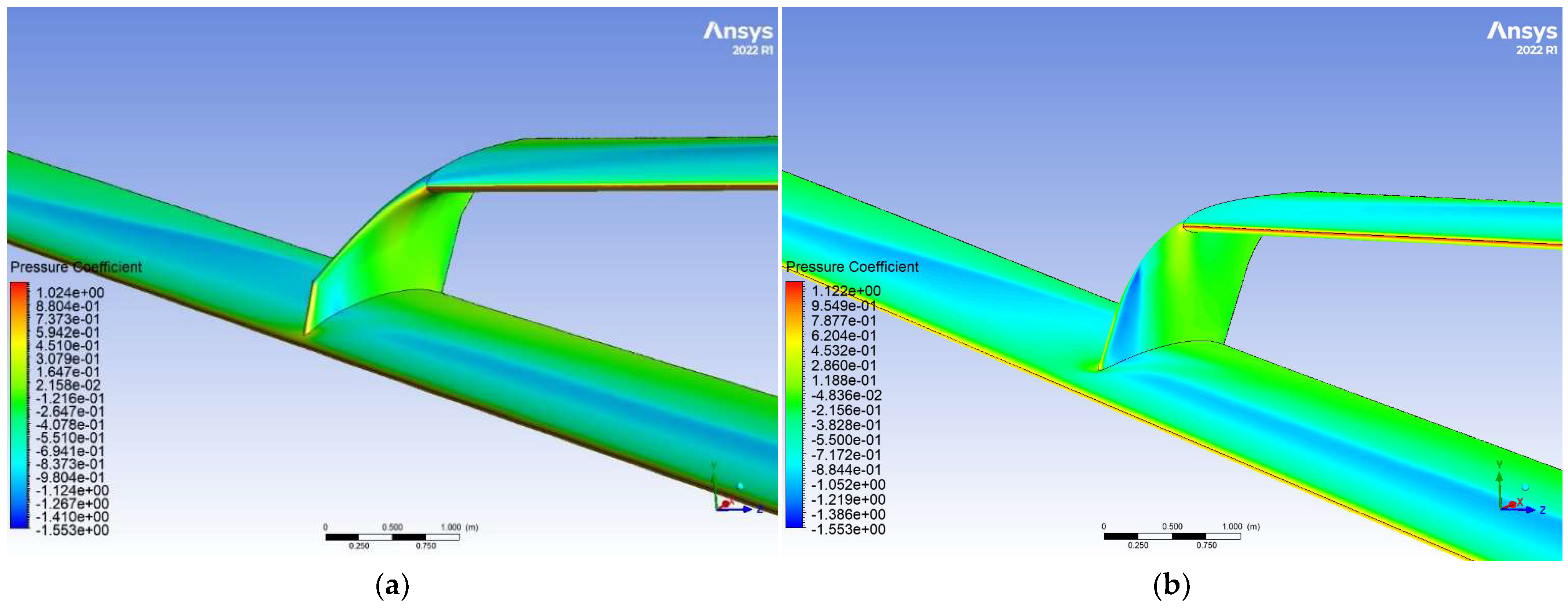
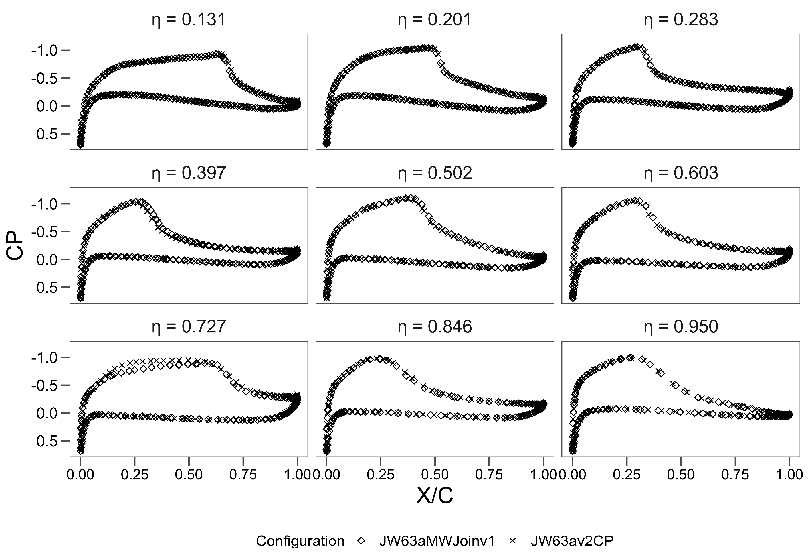
This study examines the aerodynamic performance of a joined-wing (JW) aircraft design based on the NASA Common Research Model (CRM), aiming to assess its potential for efficient commercial transport or cargo aircraft at transonic speed (Mach 0.85). The CRM wing, optimised for transonic flight, was transformed into a JW design featuring a high-aspect-ratio main wing. An initial parametric study using the vortex lattice minimum drag panel method identified viable designs. The selected JW configuration, comprising front and rear wings joined by a vertical fin, was analysed using ANSYS Fluent to understand flow interactions and aerodynamic performance. At an angle of attack (AoA) of −1°, the JW design achieved a peak lift-to-drag ratio (L/D) of 17.45, close to the CRM’s peak L/D of 19.64 at 2°, demonstrating competitive efficiency. The JW’s L/D exceeded the CRM’s between AoA −3° and 0.8°, but the CRM performed better above 0.8°, with differences decreasing at a higher AoA. Based on induced drag alone, the JW outperformed the CRM across AoA −3° to 8°, but flow complications restricted its L/D advantage to a small, low AoA range. A strong shock on the vertical fin’s inboard side due to high incoming flow speed delayed shock formation on the main wing near the joint. Optimising the vertical fin shape slightly improved L/D, suggesting potential for further enhancements or that other design factors significantly affect JW performance. This study provides insights into JW aerodynamics at transonic speeds, revealing its potential benefits and challenges compared to the CRM design.
Keywords: joined wing; high aspect ratio; computational fluid dynamics; common research model; vortex lattice minimum drag; transonic aerodynamics joined wing; high aspect ratio; computational fluid dynamics; common research model; vortex lattice minimum drag; transonic aerodynamics