Article

Liquid–Liquid Flow and Mass Transfer Enhancement in Tube-in-Tube Millireactors with Structured Inserts and Advanced Inlet Designs

1
College of Material Engineering, Fujian Agriculture and Forestry University, Fuzhou 350108, China
2
Fujian Fiber Inspection Center, Fuzhou 350026, China
3
School of Chemical Engineering and Technology, Tianjin University, Tianjin 300350, China
*
Authors to whom correspondence should be addressed.
Fluids 2025, 10(2), 26; https://doi.org/10.3390/fluids10020026
Submission received: 2 December 2024 / Revised: 3 January 2025 / Accepted: 23 January 2025 / Published: 24 January 2025
(This article belongs to the Special Issue Mass Transfer in Multiphase Reactors)

Abstract

:
Liquid–liquid mass transfer is crucial in chemical processes like extraction and desulfurization. Traditional tube-in-tube millireactors often overlook internal flow dynamics, focusing instead on entry modifications. This study explores mass transfer enhancement through structured inserts (twisted tapes, multi-blades) and inlet designs (multi-hole injectors, T-mixers). Using high-speed imaging and water–succinic acid–butanol experiments, flow patterns and mass transfer rates were analyzed. Results show annular and dispersion flows dominate under tested conditions with structured inserts lowering the threshold for dispersion flow. Multi-hole injectors improved mass transfer by over 40% compared to T-mixers in plain tubes, while C-tape inserts achieved the highest volumetric mass transfer coefficient (2.43 s−1) due to increased interfacial area and droplet breakup from energy dissipation. This approach offers scalable solutions to enhance tube-in-tube millireactor performance for industrial applications.

1. Introduction

Mass transfer between liquid phases is essential in numerous chemical engineering processes, such as biphasic reactions, emulsion formation, gasoline desulfurization, and liquid–liquid extraction [1]. Microreactors have gained significant attention for their ability to intensify liquid–liquid mass transfer thanks to their small dimensions, large interfacial areas, precise fluid control, enhanced mixing, modular design, and superior safety and controllability [2]. However, the narrow channels of microreactors often limit throughput, posing challenges for industrial-scale applications.
Tube-in-tube millireactors provide a promising alternative by combining small characteristic dimensions and high specific surface areas with significantly enhanced throughput [3,4]. Typically, these reactors consist of inner and outer tubes with reactions occurring in the annular space between them. The radial dimension of this annular channel is in the submillimeter range, while its circumferential dimension can extend to several centimeters, offering a cross-sectional area substantially larger than that of conventional microchannel reactors. Additionally, their circular tube structure ensures excellent pressure resistance and allows assembly using T-junctions or flanges. Tube-in-tube microreactors have been effectively employed in various processes, including nanomaterial synthesis [5,6], emulsification [7,8], and gas absorption and reaction systems [9,10].
Tube-in-tube millireactors have demonstrated significant potential in improving liquid–liquid mass transfer. For example, Li et al. [11] developed a pore-array tube-in-tube microreactor (PA-TMC) and evaluated its performance using a water–benzoic acid–kerosene system. This reactor achieved an overall volumetric mass transfer coefficient (KLa) ranging from 3.6 to 153 min−1, substantially surpassing conventional stirred tanks and packed columns. Despite these advancements, current research on tube-in-tube reactors largely focuses on inlet mixing, often neglecting the importance of maintaining effective two-phase [12] flow disturbance within the annular channel. This limitation can result in rapid flow stabilization and a significant decline in mass transfer efficiency.
Unlike single-phase processes, where near-complete mixing is often achieved near the inlet, two-phase mass transfer requires the entire channel length for effective interaction. To address this challenge, strategies such as incorporating series micro-mixers or designing intricate channel geometries are commonly employed [13,14,15]. These approaches aim to enhance energy dissipation throughout the reactor while minimizing droplet coalescence and preventing the reformation of stratified or slug flows. Notable examples include the continuous plate reactors developed by Lonza and Corning [16]. And static mixers are also used to enhance two-phase mass transfer [17,18,19,20], such as Kenics, Sulzer and BTR. Furthermore, Plouffe et al. investigated the effects of various solvent pairs [13] and micro-mixer structures [21], concluding that the dispersed flow regime generally delivers the highest mass transfer efficiency. In this regime, the mass transfer coefficient is primarily governed by the average energy dissipation rate and the solvent pair properties rather than the reactor’s geometry. These findings emphasize that the optimal design for microreactors targeting rapid liquid–liquid reactions should focus on achieving dispersed flow with minimal energy dissipation.
To reduce droplet size, increase interfacial area, and enhance mass transfer, this study integrates various insert structures and multi-hole injection feeds into the annular channels of tube-in-tube milli-reactors. While previous studies have demonstrated the effectiveness of these reactors in single-phase mixing and heat transfer [3,22], their performance under liquid–liquid two-phase flow conditions remains largely unexplored. This research investigates the influence of curvature-based and collision-based insert components on flow patterns and mass transfer in liquid–liquid systems. In two-phase systems, inlet conditions play a critical role in achieving dispersed flow. The initial stage of droplet formation significantly impacts droplet size, velocity, and subsequent mass transfer efficiency downstream with up to 3–50% of total mass transfer potentially occurring at the inlet [23]. To evaluate the effects of inlet conditions, this study employs two distinct feed mechanisms: multi-hole injectors and T-type mixers. By elucidating how inlet structures and internal components influence flow patterns, this work addresses a key research gap in the field of tube-in-tube microreactors. Additionally, it provides valuable insights that lay the groundwork for future industrial applications, where optimizing mass transfer and flow patterns is essential for process intensification.

2. Materials and Methods

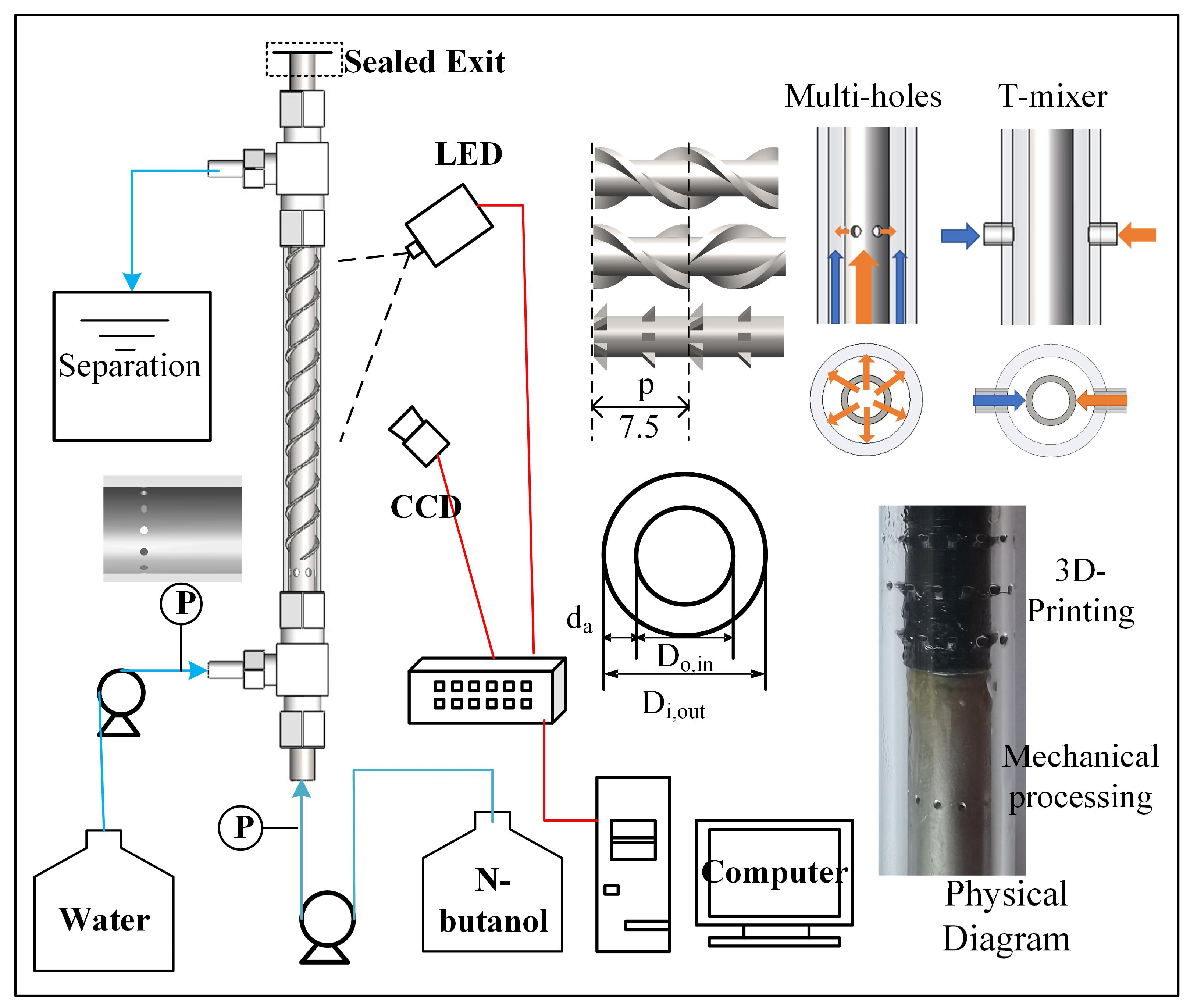
2.1. Visualization Experiments

High-speed imaging, renowned for its simplicity and direct observation capabilities, was extensively utilized to study two-phase flow dynamics in this experiment, as depicted in Figure 1. The organic phase (n-butanol) and the aqueous phase (water) were pre-saturated by stirring overnight prior to introduction into the reactor. Both phases were pumped using high-performance liquid chromatography (HPLC) systems with flow rates ranging from 6 mL/min to 80 mL/min. After mixing at a designated point, the mixture was allowed to stabilize while flowing through the main channel. To mitigate strong reflections from the small-diameter circular tubes, an LED cold light source with minimized intensity illuminated the observation section. Flow patterns were captured using a Dantec high-speed CCD camera, which is capable of operating at a maximum frame rate of 85 Hz with shutter speeds ranging from 1/110 s to 1/110,000 s.
The experiments included two feed methods: the multi-hole injection feed method, where the aqueous phase entered the outer tube, while the organic phase was introduced into the inner tube and jetted into the annular channel through micro-holes on the inner tube wall; and the T mixer, where both phases were introduced into the annular channel via a T-type mixer from opposite sides.
The experimental study examined several channel structures: a plain tube, a helical twisted tape tube (N-tape), a crossed helical twisted tape tube (C-tape), and a multi-blades tube (M-blades), all fabricated via UV-cured 3D printing. The setup was vertically aligned with fluids entering from the bottom and exiting from the top. The inner tube had an outer diameter of 3 mm, while the outer tube had an inner diameter of 5 mm. Each twisted tape segment measured 7.5 mm in length, and the multi-blade structure featured rows of six blades each, which was inclined at 45° and rotated 30° relative to adjacent rows. The total length of the reactor was 500 mm.

2.2. Characterization of the Mass Transfer Performance

The liquid–liquid mass transfer efficiency of the reactor was studied using the n-butanol–water system with succinic acid as the transferring solute. This system is recommended by the European Federation of Chemical Engineering as a standard for liquid–liquid extraction testing [24]. Materials used in the experiment included succinic acid (99%, Shanghai Macklin), n-butanol (99%, Tianjin Damao), and deionized water. Prior to the experiment, the deionized water and n-butanol were mutually saturated to ensure that succinic acid was the sole transferring component. The properties of saturated water (aqueous phase) and saturated n-butanol (organic phase) at 293 K are listed in Table 1. At the start of the experiment, succinic acid was dissolved into the organic phase at a mass concentration of 2 wt%.
The experimental apparatus used for measuring the mass transfer coefficient in two-phase flow is identical to that utilized in visualization studies. A separatory funnel at the outlet allows for the separation of the organic and aqueous phases post-experimentation. Flow rates for both phases are maintained between 6 mL/min and 80 mL/min. To ensure complete wetting of the internal surfaces, the apparatus is flushed with the aqueous phase at a low rate for 5 min before each experiment. After setting the flow rates, the experimental duration is established to be at least three times the theoretical residence time to ensure that steady-state conditions are achieved. If this period is less than two minutes, the duration is extended to a minimum of two minutes. Following their passage through the reaction system, the mixed phases enter the separatory funnel, where the aqueous phase is collected at the bottom for analysis. The concentration of succinic acid in the aqueous phase is determined via titration with a 0.1 mol/L sodium hydroxide solution. Each operational condition is replicated at least three times to ensure reliability with three samples collected and analyzed per trial. The resulting measurements indicate that the average standard deviation of the succinic acid concentration is below 5.4%.
In addition to the primary mass transfer processes occurring within the mixer and reaction channel, significant secondary mass transfer is also observed in the separatory funnel. To accurately quantify the mass transfer exclusively within the reactor, it is essential to mitigate and correct for effects emanating from the collection area. To address this, the improved time extrapolation method developed by Li et al. [26] was employed. During the experiment, samples were taken at time intervals equivalent to 1, 2, and 3 times the residence time. These concentration measurements were plotted against time, and a regression line was fitted through the data points. This line was subsequently extrapolated backward to the Y-axis to determine the initial concentration of succinic acid at the reactor outlet, effectively isolating the reactor’s intrinsic mass transfer characteristics.

2.3. Data Simplification

The capillary number ( C a ) is the ratio of viscous force to interfacial tension and is proportional to velocity:
C a = μ u γ
where u is the apparent velocity, μ represents viscosity, and γ represents interfacial tension.
The Reynolds number ( R e ) measures the relative strength of inertial forces and viscous forces, therefore,
Re = ρ d h u μ
where ρ is the density, and dh represents the hydraulic diameter.
The Weber number ( W e ) is the product of Re and Ca. It represents the ratio of inertial forces to interfacial tension and is proportional to the square of the velocity.
W e = ρ d h u 2 γ
The Bond number ( B o ) is the ratio of buoyancy to interfacial forces:
B o = Δ ρ d h 2 g γ
where Δ ρ represents the density difference, and g is the gravitational acceleration.
To investigate the effects of inlet configuration and channel design on mass transfer performance, the volumetric mass transfer coefficients k 1 a 1 for the T-junction and multi-hole feed section, as well as the overall reactor volumetric mass transfer coefficient k 2 a 2 , were calculated based on the aqueous solution:
k 1 a 1 = C a q , 1 C a q , 0 t 1 C a q , 0 C a q , 0 C a q , 1 C a q , 1 ln C a q , 0 C a q , 0 / C a q , 1 C a q , 1
k 2 a 2 = C a q , 2 C a q , 0 t 2 C a q , 0 C a q , 0 C a q , 2 C a q , 2 ln C a q , 0 C a q , 0 / C a q , 2 C a q , 2
where C a q , i represents the molar concentration of succinic acid in the aqueous phase. Subscripts 0, 1, and 2 correspond to the mixer inlet, mixer outlet, and the outlet of the annular reactor system, respectively. The equilibrium concentration C a q , i * is calculated as follows:
C a q , i = C o r , i λ
where λ = 1.17 is the partition coefficient of succinic acid between the organic and aqueous phases [24]. The concentration of succinic acid in the organic phase, C o r , i , is calculated using the mass balance equation:
Q o r C o r , 0 + Q a q C a q , 0 = Q o r C o r , i + Q a q C a q , i
Additionally, the overall extraction rate E quantifies the extent of extraction within the reactor. It is expressed as the ratio of the concentration difference between the inlet and outlet to the maximum possible concentration difference between the inlet concentration and the equilibrium concentration of the two phases.
E ( % ) = 100 C a q , i C a q , o C a q , i C a q
The volume flow ratio ( q ) is shown below:
q = Q a q Q o r
The inlet mass transfer contribution rate (y) measures the percentage of mass transfer occurring in the inlet section relative to the total mass transfer within the reactor. Both feeding methods are calculated under plain annular tube conditions.
y = C a q , 1 C a q , 0 C a q , 2 C a q , 0
C a q , 1 and C a q , 2 represent the aqueous phase concentrations at the mixer outlet and reactor outlet, respectively.
The average energy dissipation rate is shown below:
ε ¯ = Δ P Q t o t ρ c V R = Δ P ρ c τ

3. Results and Discussion

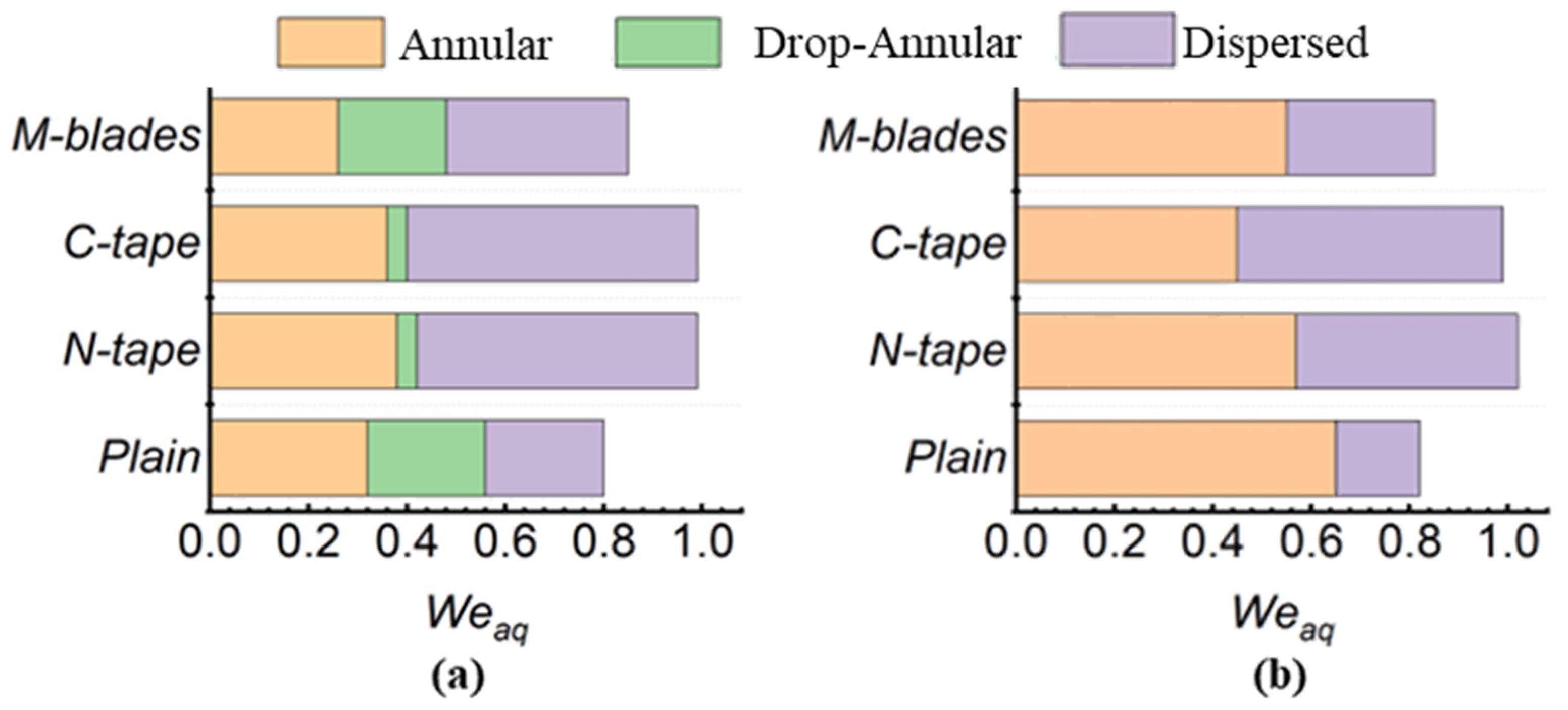
3.1. Two-Phase Flow Patterns in Tube-in-Tube Millireactors

The investigation into two-phase flow patterns within an annular millireactor was conducted across total flow rates ranging from 0 to 160 mL/min, as shown in Figure 2. Within this range, stratified and annular flows were the predominant flow patterns. At higher flow rates, droplet detachment from the main flow occurred, leading to a droplet-annular flow. As flow rates increased further, the annular flow destabilized, producing droplets significantly smaller than the channel diameter. These droplets eventually transitioned into a dispersed flow, becoming too small to be visible to the naked eye. Interestingly, unlike prior literature where droplet flow typically precedes stratified flow, our observations revealed a direct transition to stratified flow. With increased organic phase flow rates, the flow enveloped the inner tube, establishing a stable annular flow. Observational challenges were particularly pronounced in tube-in-tube millireactors compared to empty tube or plate reactors, as the inner tube obstructed light and caused significant scattering, degrading image quality.
Within our study, annular and dispersed flows were the primary patterns observed, each with distinct characteristics and potential applications. A consistent transition from annular to dispersed flow was noted as the flow velocities increased. The inner tube, fabricated via 3D printing from a photocurable resin, exhibited oleophilic properties that enhanced the organic phase’s adhesion to the tube surface, promoting stable annular flow. Although annular flow typically has limited mass transfer efficiency due to its smaller contact area, it facilitates a distinct phase interface crucial for controlled solute transfer and precise two-phase contact time [27]. To improve extraction efficiency in annular flow, adjustments to flow rates and increased contact length are necessary to optimize residence time. However, viscosity differences between phases can create pressure gradients that destabilize the interface, requiring a balance between reactor length and pressure drop [12]. Stability may be further enhanced by incorporating microstructures, such as micropillars or rough walls, to maintain the interface [28]. Dispersed flow, characterized by its superior mass transfer efficiency due to the maximal two-phase contact area, is ideal for enhancing mass transfer. Achieving dispersed flow at lower flow rates can be facilitated by introducing obstacles that increase local energy dissipation and reduce droplet size while avoiding curved structures [21]. However, dispersed flow poses challenges in controlling contact time and achieving uniform droplet distribution, necessitating strategies to maintain consistent droplet sizes.
Figure 3 shows the two-phase flow patterns in a water–n-butanol system within a tube-in-tube millireactor, which were classified using the Weber number ( W e ) [2]. At lower flow rates with multi-hole injection, annular flow dominates. As flow rates increase, droplets detach, transitioning the flow to a dispersed state. The channel structure significantly influences the Weber number thresholds for these transitions. In an empty annular tube, droplets detach when the aqueous Weber number ( W e a q ) exceeds 0.32, which is facilitated by micro-hole feed structures. At W e a q = 0.56, rapid droplet detachment transitions the flow to dispersed. In the N-tape tube, twisted tape guides droplets along the inner wall coated with the organic phase, raising the detachment threshold to W e a q = 0.44. This aligns with studies showing curvature promotes parallel flow and delays detachment. The C-tape tube, combining swirling and shearing effects, requires W e a q = 0.36 for detachment but transitions to dispersed flow at W e a q = 0.40. In contrast, multi-fin structures induce collisions, lowering detachment to W e a q = 0.26, but stabilize the flow with dispersal occurring at W e a q = 0.48. These results highlight the critical role of structure in flow dynamics and transitions.
The extensive annular flow observed in this study is due to the low interfacial forces of the n-butanol–water system and the influence of gravity. Low interfacial forces hinder droplet and slug flow formation, especially in channels with larger hydraulic diameters. The reactor’s dimensions (2 mm diameter, centimeter-level circumference) further reduce interfacial force effects. Gravity, confirmed by Bond numbers ( B o > 0.1), drives the dominant annular flow [23]. Variations in flow patterns across structures (N-tape, multi-blades, plain tube) reflect increasing gravitational effects ( B o = 0.14, 0.19, 0.23) and decreasing interfacial forces, expanding the annular flow regime.
Figure 3b illustrates the flow pattern diagram for two fluid streams introduced via a T-type mixer, which provides greater stability compared to the multi-hole injection method. Within the examined range, this approach prevented droplet detachment, allowing a seamless transition from annular to dispersed flow. Notably, the transition from annular to dispersed flow occurred at a higher aqueous Weber number ( W e a q ), highlighting the significant influence of inlet conditions on droplet formation dynamics. In contrast, the multi-hole injection method, characterized by higher outlet velocities, generates pronounced localized shear forces that facilitate droplet breakup. This mechanism leads to an earlier onset of dispersed flow at lower channel flow rates. However, with the T-type mixer, the colliding fluid streams impact the inner tube wall, and at lower flow rates, fail to produce sufficient localized turbulence. Instead, the streams merge directly onto the inner tube surface, quickly establishing a stable annular flow. The inner tube modifies the dynamics at the collision point by dampening kinetic energy, favoring the stabilization of annular flow. As flow velocity increases and surpasses a critical kinetic energy threshold, the annular flow interface destabilizes, resulting in a transition to dispersed flow. This dynamic interplay underscores the importance of inlet design in influencing flow patterns and transitions within tube-in-tube millireactors.

3.2. Mass Transfer Capability of the Inlet Section

3.2.1. Contribution of Mass Transfer in the Inlet Section

In traditional extraction processes, inlet design mainly ensures uniform fluid distribution, with minimal impact on mass transfer, especially in systems with large dimensions. However, in microreactors, where space is limited, micromixers like T-type mixers significantly enhance two-phase mass transfer. This has spurred research into how inlet designs affect performance. Using the method proposed by Li et al. [26], the mass transfer contribution rate ( y ) of the inlet section was calculated, providing a quantitative measure of its impact and emphasizing its importance in microreactor efficiency.
Figure 4 demonstrates that the y of the multi-hole injection system consistently exceeds that of the T-type mixer across the studied Reynolds number range. Specifically, y values for the multi-hole system range from 68% to 90% compared to 22% to 60% for the T-type mixer. These findings align with Li et al.’s observations that increasing channel length from 100 mm to 1000 mm results in only marginal improvements in extraction rates, confirming that most two-phase mass transfer occurs in the inlet stage. The multi-hole injection system’s superior performance is due to two key mechanisms: it significantly increases local energy dissipation, which directly enhances the mass transfer rate, and it reduces the size of organic phase droplets at the inlet, resulting in a more uniform distribution of the organic phase and an expanded interfacial contact area. Functionally, the multi-hole injection system resembles an array of micro T-mixers with each pore measuring 0.2 mm—significantly smaller than the 2 mm characteristic size of the T-type mixer. This reduction in pore size substantially increases the interfacial contact area, thereby improving mass transfer efficiency and explaining the multi-hole system’s superior performance.
In the plain tube-in-tube millireactor with a straight reaction channel, mass transfer in the inlet section is lower than in capillary systems with T-type mixers, even if their characteristic dimensions are 1 mm or below. Yao et al. [29] reported higher mass transfer efficiency (35–85%) in T-type mixers, which was attributed to direct collision and fluid engulfment. In contrast, the tube-in-tube system sprays phases onto the inner tube wall, reducing energy dissipation and interfacial surface area, especially during scaling up. Multi-hole injection designs can recreate microscale phase interactions in larger reactors, mitigating efficiency losses.
A limitation of the previous method for determining inlet section mass transfer contribution is its inaccuracy near mass transfer limits or equilibrium. To overcome this, Li et al.’s [26] equilibrium concentration ( C a q e q ) was adopted, representing the succinic acid concentration in the aqueous phase at liquid–liquid equilibrium.
y e q = C a q , 1 C a q , 0 C a q e q C a q , 0
Figure 5 illustrates the relationship between equilibrium mass transfer efficiency ( y e q ) and the Re for two different inlet structures in the tube-in-tube millireactor. Due to the high extraction rates observed, mass transfer is often equilibrium-limited, making the equilibrium-based formula particularly relevant for designing small-scale reactors. Unlike the direct relationship between y and Re, the y e q versus Re curve initially decreases and then increases for both inlet configurations. This behavior reflects a trade-off between the mass transfer time (or residence time) and the volumetric mass transfer coefficient.
As Re increases by elevating the superficial velocity, the mass transfer time decreases, reducing residence time, but local energy dissipation increases, enhancing the mass transfer coefficient. At lower flow rates, the increased volumetric mass transfer coefficient does not fully compensate for the shortened mass transfer time, resulting in an overall decline in y e q . However, at higher flow rates, the elevated mass transfer coefficient compensates for the reduced residence time, causing y e q to rise. For the multi-hole injection system, y e q remains above 40% across the entire Re range and exceeds 70% at both low and high superficial velocities, highlighting its superior contribution to mass transfer efficiency. In contrast, the T-type mixer consistently shows y e q values below 40% and is expected to exhibit further declines with increasing reactor diameter. This suggests that specialized designs, such as the multi-hole injection system, are essential to enhance mass transfer capabilities in reactors.

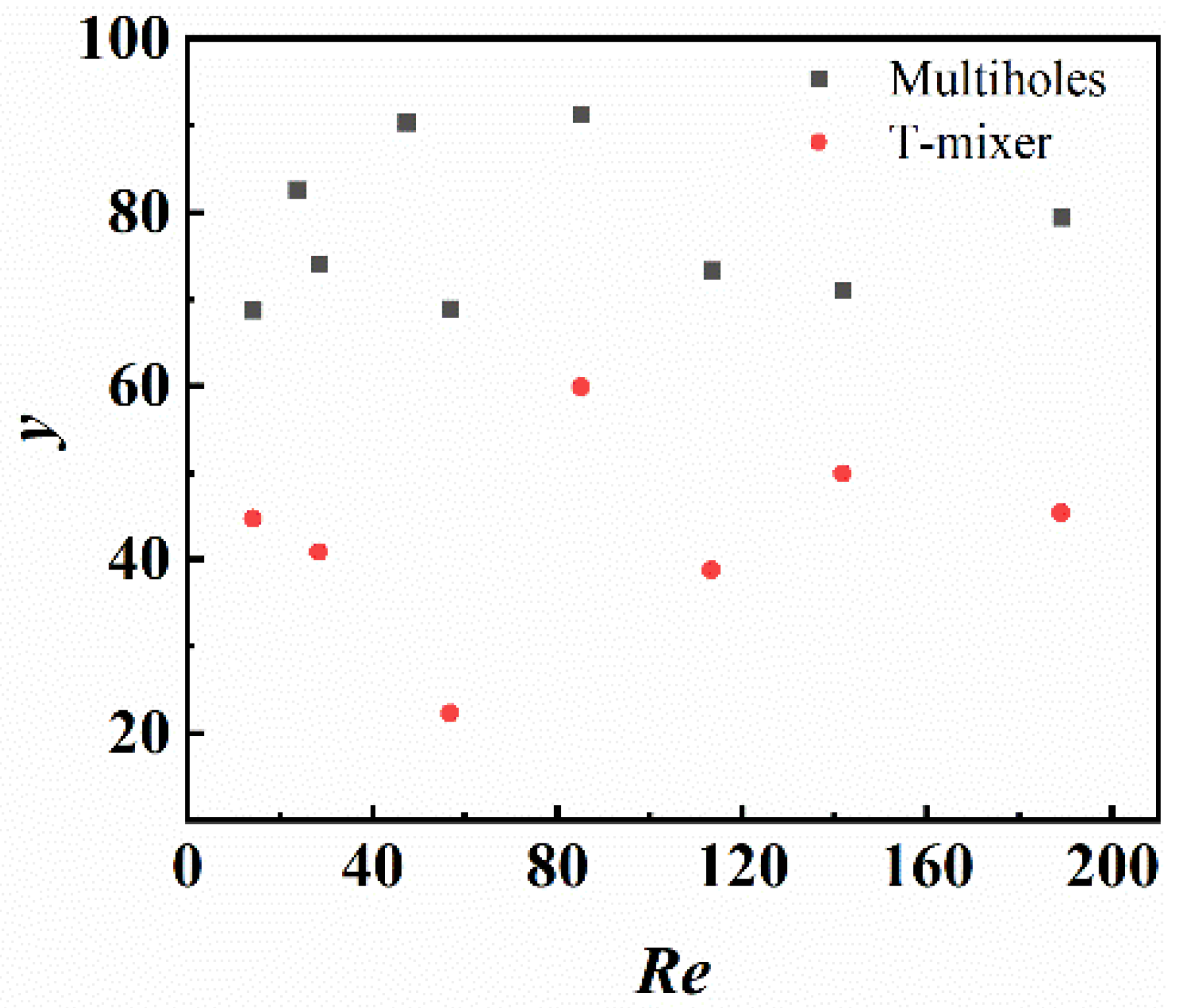
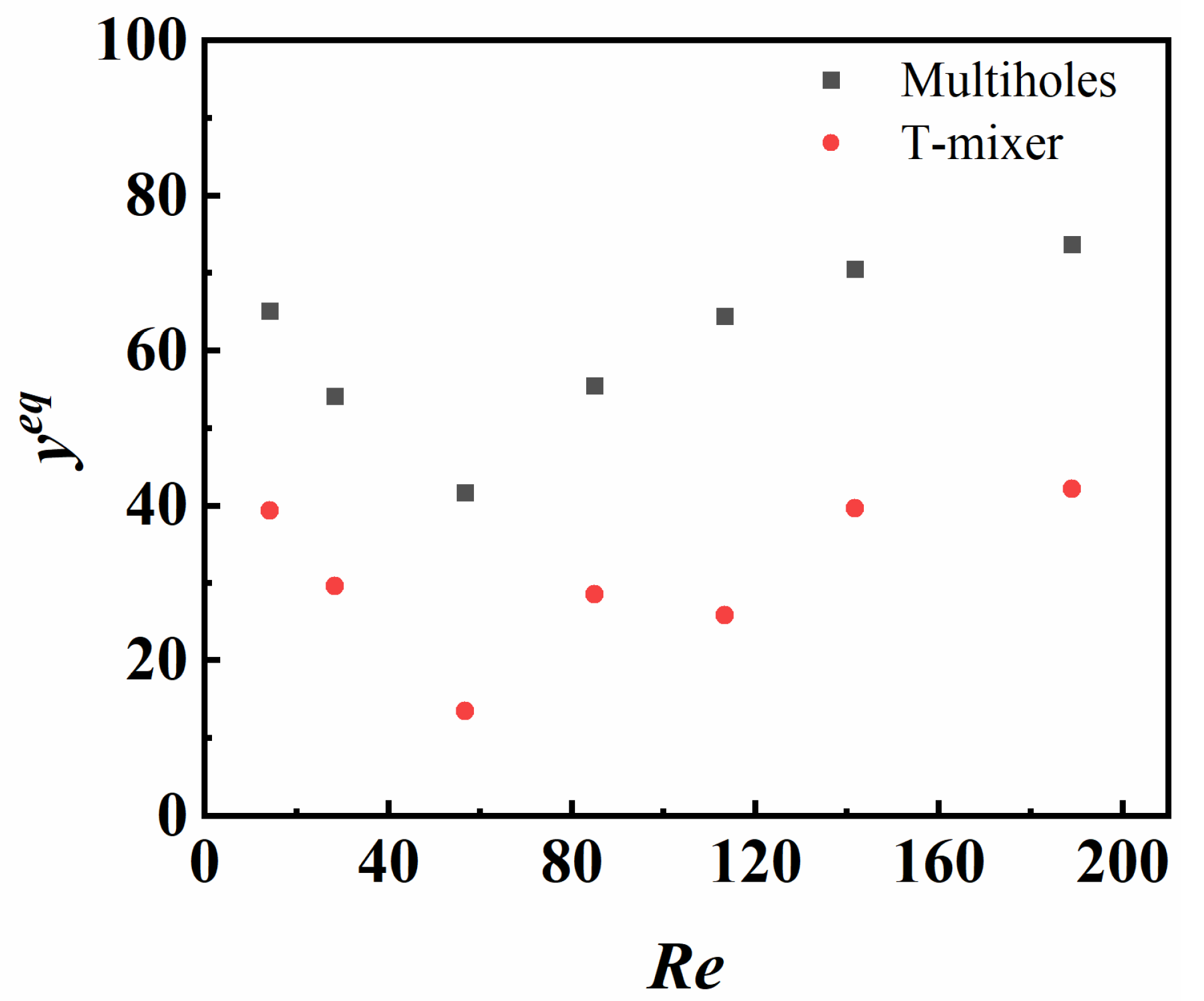
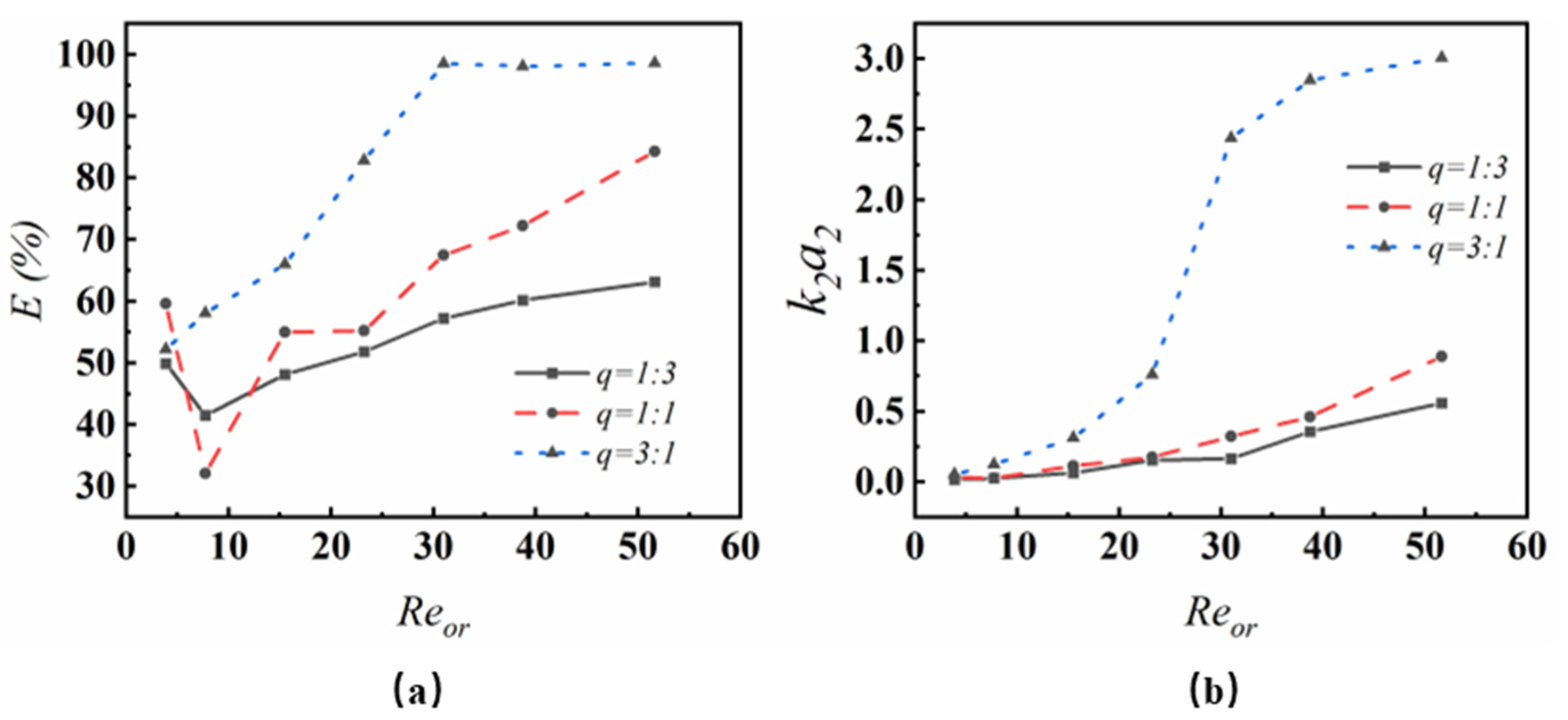
3.2.2. Influence of Apparent Reynolds Number on Mass Transfer in the Inlet Section

Figure 6 illustrates how the overall mass transfer coefficient, k 1 a 1 , varies with the apparent Re for two inlet configurations. For both designs, k 1 a 1 increases with Re; however, the rate of increase is significantly greater for the multi-hole injection configuration. At Re = 180, the k 1 a 1 value for the multi-hole injection is six times higher than that of the T-type mixer, reflecting a substantial enhancement driven by the presence of micro-holes that generate localized turbulence. The local Re within the micro-holes, based on their diameter, exceeds 1000, resulting in the formation of numerous droplets around the micro-hole array, vigorous fluid motion, and localized recirculation zones. These phenomena amplify mass transfer by intensifying the interfacial interaction between phases. Notably, when Re exceeds 120, the k 1 a 1 value for the multi-hole injection shows a dramatic surge, corresponding to a transition from annular-droplet flow to dispersed flow. This transition significantly increases the interfacial contact area between the two phases, further enhancing the overall mass transfer efficiency. The pronounced performance improvement of the multi-hole injection system underscores its ability to leverage micro-scale turbulence and flow transitions to achieve superior mass transfer rates compared to the T-type mixer, particularly at higher flow regimes.
In contrast, the T-type mixer exhibits only minimal increases in k 1 a 1 at lower Re values. However, when Re exceeds 100, a more noticeable rise in k 1 a 1 is observed, which can be attributed to the onset of localized slug flow. According to Sattari-Najafabadi et al. [30], slug flow at low velocities has limited impact on the volumetric mass transfer coefficient and negligible influence on the mass transfer area with internal circulation within the slugs playing a dominant role. As the superficial velocity increases, the intensity of internal circulation within the slugs grows, contributing significantly to the observed rise in k 1 a 1 . Beyond Re > 100, the organic and aqueous phases are sprayed onto the inner tube wall with high kinetic energy, resulting in collisions that stretch, deform, and fold the phase interface. These dynamic interfacial interactions increase the interfacial contact area and promote surface renewal, collectively driving the substantial enhancement in k 1 a 1 . This demonstrates that while the T-type mixer lags behind the multi-hole injection system in overall performance, the interplay of flow dynamics and interfacial phenomena at higher Re values enables a marked improvement in mass transfer efficiency.

3.3. Mass Transfer in the Tube-in-Tube Millireactor System

3.3.1. Effect of Volume Flow Ratio ( q ) on Volumetric Mass Transfer Coefficient in a Plain Tube-in-Tube Millireactor

Figure 7 illustrates the effects of the volume flow ratio ( q ) on the extraction rate ( E ) and volumetric mass transfer coefficient ( k 2 a 2 ) in a smooth tube-in-tube millireactor with a multi-hole organic phase injection. When the organic-phase Reynolds number ( R e o r ) exceeds 15, both E and k 2 a 2 increase with q and R e o r . At R e o r > 30 and q = 3, E approaches 100%, indicating highly efficient extraction. However, for R e o r < 15, the relationship between E , R e o r , and q is non-monotonic, reflecting a trade-off between shortened extraction time and enhanced mass transfer efficiency. In this region, E initially declines but subsequently increases with higher R e o r and q .
Interestingly, k 2 a 2 also increases with q , contrasting with earlier studies. This can be attributed to the experimental design, where adjustments in the aqueous-phase feed rate while maintaining a constant organic-phase flow lead to an increase in the apparent Reynolds number. At lower Reynolds numbers, the flow regime is primarily annular. As q rises, the relative velocity between phases increases, intensifying interfacial wave motion and promoting surface renewal, thereby improving k 2 a 2 . Furthermore, higher total flow rates facilitate an earlier transition to dispersed flow, which is known to exhibit significantly higher mass transfer coefficients compared to annular flow.
The impact of q on the apparent Reynolds number is evident when comparing values at the same R e o r . For q = 3, the apparent Reynolds number is notably higher than for = 1 and three times that for q = 1/3. Once R e o r surpasses 24, k 2 a 2 at q = 3$ markedly exceeds values observed at lower flow ratios, coinciding with the transition to dispersed flow. A comparative empty-tube study revealed that q = 1 achieved E > 90 at R e o r > 40, although performance generally lagged across much of the investigated range. The use of the n-butanol–water system, characterized by its low interfacial tension, results in significantly higher E compared to other systems. Plouffe et al. [21] reported that E for the butanol–water system is over 20 times higher than for toluene–water. When considering organic reactions, the selection of solvents should carefully balance mass transfer capacity with specific reaction requirements. To optimize the reactor’s performance, specialized annular structures are suggested to simultaneously enhance mass and heat transfer capabilities, as supported by the empty-tube study findings.

3.3.2. The Effect of Annular Gap Width on Volumetric Mass Transfer Coefficient in Plain Tube-in-Tube Millireactors

Figure 8 illustrates the effect of varying the annular gap width on mass transfer performance, revealing opposing trends at different flow rates. Below a flow rate of 40 mL/min, the extraction rate ( E ) increases with wider gaps. This enhancement is attributed to the increased residence time provided by larger gap widths, which allows for extended interaction between the phases, thereby facilitating mass transfer. In contrast, at flow rates exceeding 50 mL/min, E decreases with increasing gap width. This decline likely stems from reduced velocities in wider gaps, which impair surface renewal—a critical factor for efficient mass transfer.
Regardless of the flow rate, the volumetric mass transfer coefficient ( k 2 a 2 ) consistently declines as the gap width increases. This trend is primarily due to lower flow velocities in wider gaps, which result in reduced interfacial turbulence and less efficient surface renewal. Additionally, the behavior of the organic phase at the multi-hole mixer outlet is significantly influenced by the gap width. For instance, with a 1.5 mm gap, the dispersed organic phase struggles to penetrate the continuous phase and reach the outer wall, predominantly adhering to an annular flow pattern along the inner wall. This restricted dispersion limits the ability of k 2 a 2 to rise with increasing flow rates.
In contrast, a narrower gap of 0.5 mm facilitates the organic phase’s ability to reach and rebound off the outer wall, generating a chaotic, oscillating dispersion zone. Observations indicate that after exiting the multi-hole outlet, the organic phase tends to cling to the inner wall, promoting annular flow. This dynamic suggests that at narrower gaps, the interaction between the phases is more vigorous, enhancing mass transfer at lower flow rates. However, at higher flow rates, the chaotic movements induced by narrower gaps may disrupt stable phase dispersion, complicating mass transfer efficiency.

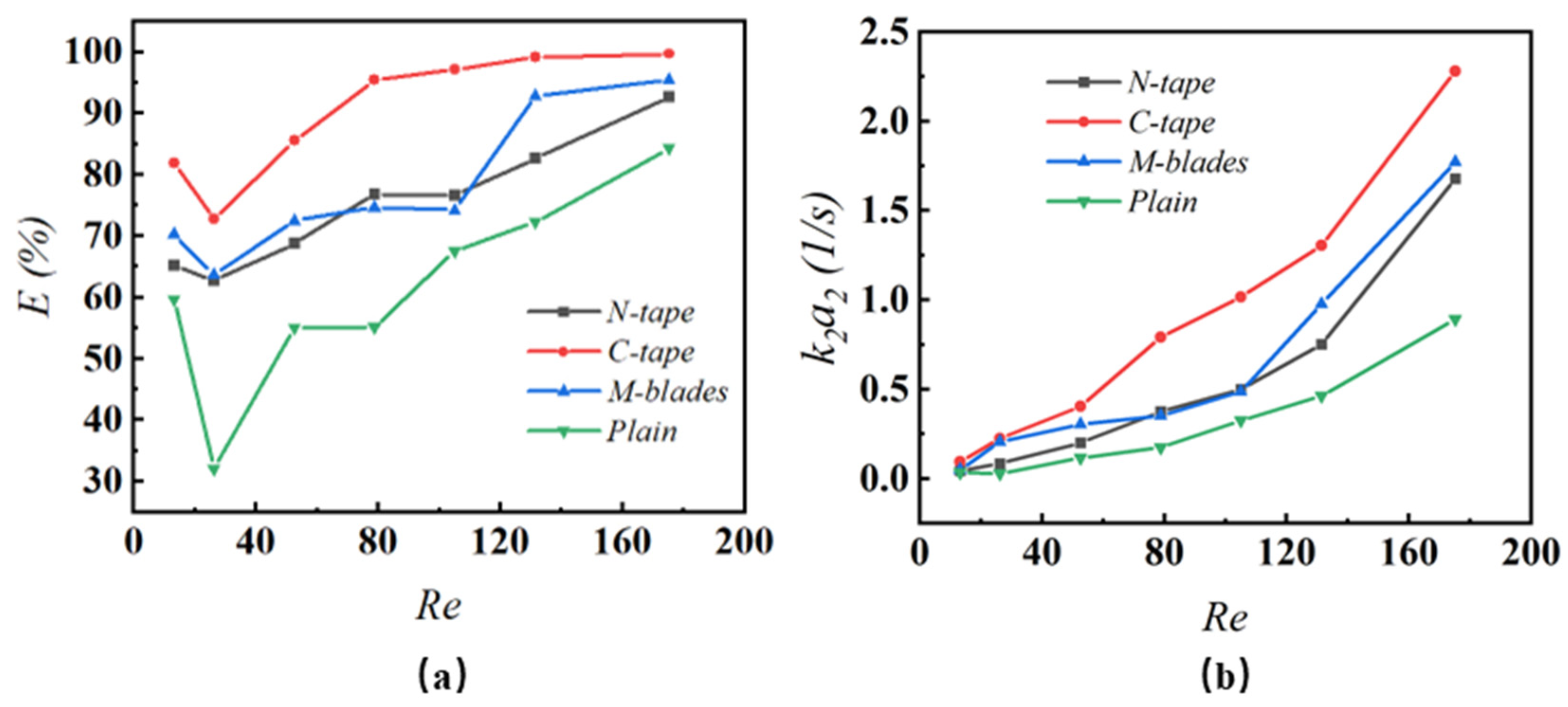
3.3.3. Two-Phase Mass Transfer in Tube-in-Tube Millireactors with Inserts

Figure 9 presents a detailed analysis of the E and k 2 a 2 as functions of the R e in tubular reactors equipped with various channel structures and multi-hole injection systems. The results reveal that at higher R e , the inclusion of internal components such as C-tape significantly enhances mass transfer dynamics, achieving an extraction rate exceeding 90%. A positive correlation between k 2 a 2 and R e is observed, with the C-tape configuration demonstrating superior performance, particularly with E surpassing 90% at R e values greater than 90.
Across all structural designs, the extraction rate follows a consistent trend: it initially increases with R e but subsequently declines as the flow rate continues to rise. At lower flow rates, the annular flow regime dominates, maximizing the interaction time between the two phases and facilitating effective mass transfer. However, as the flow rate increases, the reduced contact time between the phases begins to outweigh the advantages of enhanced interfacial area or improved surface renewal efficiency, resulting in a limitation of E . Despite the presence of specially designed inlets to promote mixing, the extraction rate in the annular flow regime remains inherently restricted.
At higher flow rates, the regime transitions from annular to dispersed flow, which promotes droplet detachment and significantly expands the two-phase contact area. This shift leads to a gradual improvement in the extraction rate. Once the flow fully transitions to the dispersed regime, the mass transfer between the phases approaches equilibrium, optimizing E . For configurations like the C-tape, a plateau in the extraction rate is observed at elevated flow rates, which is a trend consistent with findings reported in previous studies [31].
Figure 9b highlights the significant influence of R e on k 2 a 2 across various reactor designs with the C-tape configuration consistently demonstrating superior performance compared to other structures. A marked increase in k 2 a 2 for the C-tape begins at R e = 60, a threshold where its performance distinctly surpasses that of other designs, which typically do not exhibit similar improvements until R e = 100. By R e = 180, the C-tape achieves a k 2 a 2 value more than double that of a plain tubular reactor. While the N-tape and multi-fin structures perform comparably, both still significantly outperform the plain design.
The enhanced performance of these designs can be attributed to their unique mechanisms for improving mass transfer:
  • N-tape: This configuration features helical fins that induce fluid rotation, effectively increasing the interfacial area and promoting surface renewal, which are critical for mass transfer.
  • Multi-blade structure: Staggered fins in this design create flow disturbances and compression through narrow gaps. By splitting and recombining the flow, this structure extends the flow path and intensifies mass transfer processes.
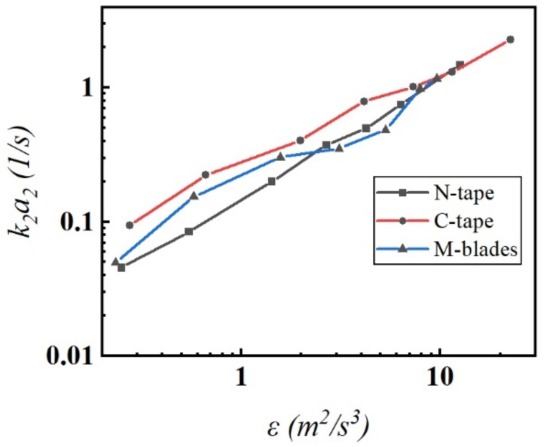
  • C-tape: The most effective design, the C-tape combines fluid rotation and segmentation to induce viscous shear and interfacial deformation. These mechanisms enhance droplet breakup in the dispersed phases, driving the earlier and steeper increase in k 2 a 2 observed with this design.
In dispersed flow conditions, k 2 a 2 is significantly enhanced compared to annular flow, emphasizing the critical role of early flow regime transitions in improving mass transfer efficiency. Droplet generation and size reduction are pivotal in this process, which are driven by energy dissipation. Higher energy dissipation rates enhance eddy collisions and droplet breakup, thinning the boundary layers around droplets, reducing convective resistance, and thereby increasing mass transfer rates [32].
Figure 10 illustrates the relationship between k 2 a 2 and the energy dissipation rate ( ε ¯ ), as derived from Equations (5)–(12), for reactors with multi-hole injection systems across a R e range from 20 to 180. In the regime where R e < 80, the N-tape configuration exhibits lower k 2 a 2 values compared to other designs. This is attributed to its stable flow characteristics, which limit droplet formation. The centrifugal forces generated within the twisted channel structure constrain interfacial contact by reducing droplet dispersion, thereby hindering mass transfer efficiency. At R e > 140, all configurations transition to dispersed flow. In this regime, the dimensions of secondary flow structures become smaller than those of the reactor, resulting in a high-energy environment where k 2 a 2 is primarily governed by the frequency of droplet collisions and the kinetic energy of these interactions, as noted in reference [30]. Under such conditions, the influence of geometry on k 2 a 2 diminishes, and the values across different designs converge at similar ε ¯ levels.
The strategic design goal, particularly for annular gap structures, is to achieve dispersed flow at the lowest possible velocity to maximize energy efficiency in mass transfer. Among the evaluated configurations, the C-tape is the most effective, facilitating the transition to dispersed flow at lower velocities. This highlights its superior capability to achieve optimal mass transfer conditions with minimal energy input.

3.4. Comparison of Tubular Millireactors with Other Designs

Table 2 compares the mass transfer coefficients obtained in this study with those reported in the existing literature, emphasizing the superior performance of tubular reactors in enhancing two-phase mass transfer. These reactors not only surpass other millimeter- and microreactors in mass transfer efficiency but also offer throughput advantages often associated with conventional microreactors. However, the reactors in this study were fabricated using 3D printing technology, raising concerns about material compatibility and heat transfer limitations in practical applications. To address these issues, alternative materials such as metals or PTFE may be necessary to expand the applicability of these designs across diverse chemical processes.
Based on these findings, future research should focus on examining how different reactor materials influence flow patterns and mass transfer efficiencies. This line of investigation will support the customization of reactor designs for specific industrial applications, optimizing their performance to align with the reactive and thermal demands of the processes they are intended to facilitate.

4. Conclusions

This study provides a comprehensive analysis of liquid–liquid mass transfer enhancement in tube-in-tube reactors, emphasizing the role of innovative inlet designs and structured internal components. The integration of helical tapes, crossed tapes, and multi-blade configurations significantly improved flow dynamics, promoting transitions to dispersed flow states at lower Reynolds numbers. Among these, the crossed-tape configuration demonstrated superior performance by inducing fluid rotation and segmentation, resulting in the highest volumetric mass transfer coefficients recorded.
The use of a multi-hole injection inlet emerged as a more effective alternative to traditional T-type mixers. By generating localized turbulence and reducing droplet sizes at the entry section, this design significantly enhanced mass transfer efficiency. Experimental results revealed that the multi-hole injection mechanism accounted for up to 90% of the mass transfer in the reactor’s inlet section, highlighting the pivotal influence of inlet design on optimizing mass transfer performance.
These findings address critical knowledge gaps in understanding two-phase flow dynamics in tube-in-tube reactors and provide scalable strategies for improving liquid–liquid mass transfer efficiency. The advancements presented here have significant implications for the development of efficient and sustainable chemical processes, particularly in industries requiring high-throughput and intensified systems. Future research should explore the impact of different materials and operational conditions on these reactors to further expand their application and optimize their performance across a wider range of chemical processing environments.

Author Contributions

Conceptualization, F.Z. and H.L.; methodology, H.L.; software, H.L.; validation, H.L., F.Z. and J.L.; formal analysis, J.L.; investigation, X.C.; resources, X.P.; data curation, Y.C.; writing—original draft preparation, H.L.; writing—review and editing, H.L.; visualization, H.L.; supervision, H.L.; project administration, H.L.; funding acquisition, R.W. All authors have read and agreed to the published version of the manuscript.

Funding

This research is funded by Fujian Province Guided Science and Technology Plan Project (2022H0031) and Jiangsu Seven Continents Green Chemical Co., Ltd.

Data Availability Statement

Additional data that support the findings of this study are available on request from the corresponding author.

Conflicts of Interest

The authors declare that this study received funding from Jiangsu Seven Continents Green Chemical Co., Ltd. The funder was not involved in the study design, collection, analysis, interpretation of data, the writing of this article or the decision to submit it for publication.

Nomenclature

Ascross-section area, mm2
daannular space size, mm
Dhmicro-hole size, mm
Di,outthe inner diameter of the outer tube, mm
dNhydrodynamic diameter of the tube-in-tube millireactor, mm
Do,inthe outer diameter of the inner tube, mm
HPLChigh-performance liquid chromatography
KLaoverall volumetric mass transfer coefficient, s−1
Llength of the reactor channel, mm
PA-TMCpore-array tube-in-tube microreactor
PrPrandtl number
ReReynolds number for reaction channel
RehReynolds number for micro-hole jet
TKEturbulent kinetic energy, m2/s2
Vinvolume flow rate in inner tube, ml/min
Voutvolume flow rate in outer tube, ml/min
yinlet mass transfer contribution rate
B o bond number
C a capillary number
E overall extraction rate
W e Weber number
g gravitational acceleration
q flow ratio
Greek letters
ΔPfluid pressure drop, Pa
εaverage turbulent dissipation rate, m2/s3
vkinematic viscosity of the fluid, m2/s
μdynamic viscosity, Pa s

References

  1. Ramji, S.; Pushpavanam, S. Liquid-liquid extraction in laminar two-phase stratified flows in capillary microchannels. Chem. Eng. Sci. 2019, 195, 242–249. [Google Scholar] [CrossRef]
  2. Al-Azzawi, M.; Mjalli, F.S.; Husain, A.; Al-Dahhan, M. A Review on the Hydrodynamics of the Liquid-Liquid Two-Phase Flow in the Microchannels. Ind. Eng. Chem. Res. 2021, 60, 5049–5075. [Google Scholar] [CrossRef]
  3. Liu, H.; Jiang, J.; Yang, N.; Xiao, Z.; Yang, X.; Wang, R. Flow and mixing in a tube-in-tube millireactor with multiholes jet and twist tapes. J. Flow Chem. 2022, 12, 353–369. [Google Scholar] [CrossRef]
  4. Liu, H.; Jiang, J.; Wang, C.; Yang, N.; Yang, X.; Wang, R. Investigations of mixing and heat transfer in a structured tube-in-tube millireactor by numerical, experimental and statistical methods. Asia-Pac. J. Chem. Eng. 2022, 18, e2843. [Google Scholar] [CrossRef]
  5. Ke, T.; Le, Y.; Wang, J.-X.; Chu, G.-W.; Chen, J.-F.; Shao, L. Cu nanoparticle preparation in a tube-in-tube microchannel reactor and encapsulation by silica. Mater. Lett. 2010, 64, 1717–1719. [Google Scholar] [CrossRef]
  6. Li, T.; Zhou, Y.; Wang, J.-X.; Shao, L.; Chen, J.-F. High-throughput emulsification in a microporous tube-in-tube microchannel device: O/W emulsion formation. Chem. Eng. J. 2013, 228, 155–161. [Google Scholar] [CrossRef]
  7. Chen, J.-F.; Chen, G.-Z.; Wang, J.-X.; Shao, L.; Li, P.-F. High-Throughput Microporous Tube-in-Tube Microreactor as Novel Gas-Liquid Contactor: Mass Transfer Study. AIChE J. 2011, 57, 239–249. [Google Scholar] [CrossRef]
  8. Pan, M.-Y.; Qian, Z.; Shao, L.; Arowo, M.; Chen, J.-F.; Wang, J.-X. Absorption of carbon dioxide into N-methyldiethanolamine in a high-throughput microchannel reactor. Sep. Purif. Technol. 2014, 125, 52–58. [Google Scholar] [CrossRef]
  9. Sun, B.; Gao, M.; Arowo, M.; Wang, J.; Chen, J.; Meng, H.; Shao, L. Ozonation of Acid Red 14 in the Presence of Inorganic Salts in a Microporous Tube-in-Tube Microchannel Reactor. Ind. Eng. Chem. Res. 2014, 53, 19071–19076. [Google Scholar] [CrossRef]
  10. Sun, B.; Li, P.; Liang, Y.; Arowo, M.; Wang, J.; Meng, H.; Chen, J.; Shao, L. Oxidation of ammonium sulfite by oxygen in a microporous tube-in-tube microchannel reactor. Chem. Eng. J. 2014, 253, 258–263. [Google Scholar] [CrossRef]
  11. Li, W.; Xia, F.; Zhao, S.; Zhang, M.; Li, W.; Zhang, J. Characterization of liquid–liquid mass transfer performance in a novel pore-array intensified tube-in-tube microchannel. AIChE J. 2020, 66, 16839. [Google Scholar] [CrossRef]
  12. Yao, C.; Zhao, Y.; Ma, H.; Liu, Y.; Zhao, Q.; Chen, G. Two-phase flow and mass transfer in microchannels: A review from local mechanism to global models. Chem. Eng. Sci. 2021, 229, 116017. [Google Scholar] [CrossRef]
  13. Plouffe, P.; Roberge, D.M.; Sieber, J.; Bittel, M.; Macchi, A. Liquid-liquid mass transfer in a serpentine micro-reactor using various solvents. Chem. Eng. J. 2016, 285, 605–615. [Google Scholar] [CrossRef]
  14. Plouffe, P.; Macchi, A.; Roberge, D.M. From Batch to Continuous Chemical Synthesis-A Toolbox Approach. Org. Process Res. Dev. 2014, 18, 1286–1294. [Google Scholar] [CrossRef]
  15. Nieves-Remacha, M.J.; Kulkarni, A.A.; Jensen, K.F. Gas-liquid flow and mass transfer in an advanced-flow reactor. Ind. Eng. Chem. Res. 2013, 52, 8996–9010. [Google Scholar] [CrossRef]
  16. Zhang, F.; Cerato-Noyerie, C.; Woehl, P.; Lavric, E.D. Intensified liquid/liquid mass transfer in corning® advanced-flow ™reactors. Chem. Eng. Trans. 2011, 24, 1369–1374. [Google Scholar]
  17. Abrofarakh, M. Effect of incorporating Sulzer SMV static mixers on the performance of direct contact membrane distillation (DCMD): A three-dimensional computational fluid dynamics (CFD) study. Sep. Purif. Technol. 2025, 359, 130606. [Google Scholar] [CrossRef]
  18. Yu, Y.; Wan, H.; Meng, H.; Zhang, P.; Han, Z.; Wang, D. A study of particle motion in Kwerk-type twisted blades: Effect of configuration on particle mixing performance by CFD-DEM. Powder Technol. 2024, 448, 120248. [Google Scholar] [CrossRef]
  19. Meng, H.; Zhang, J.; Yu, Y.; Zhao, Y.; Li, D.; Xiang, K.; Ji, Y. Investigation into Droplet Size Distribution and Turbulent Mixing Enhancement Performance in a Lightnin Static Mixer. Ind. Eng. Chem. Res. 2024, 63, 21062–21077. [Google Scholar] [CrossRef]
  20. Farahani, S.; Movahedirad, S.; Sobati, M.A. Characterization of the oil water two phase flow in a novel microchannel contactor equipped with helical wire static mixer. Sci. Rep. 2024, 14, 23369. [Google Scholar] [CrossRef]
  21. Plouffe, P.; Roberge, D.M.; Macchi, A. Liquid-liquid flow regimes and mass transfer in various micro-reactors. Chem. Eng. J. 2016, 300, 9–19. [Google Scholar] [CrossRef]
  22. Yang, N.; Xiao, Z.; Liu, F.; Jiang, J.; Liu, Z.; Liu, H.; Yang, X.; Wang, R. Enhanced liquid–liquid mass transfer in a monolithic reactor with multi-jet-channel in the circumferential array. Sep. Purif. Technol. 2024, 333, 125749. [Google Scholar] [CrossRef]
  23. Zhang, J.; Wang, Y.; Stevens, G.W.; Fei, W. A state-of-the-art review on single drop study in liquid–liquid extraction: Experiments and simulations. Chin. J. Chem. Eng. 2019, 27, 2857–2875. [Google Scholar] [CrossRef]
  24. Misek, T.; Berger, R.; Schröter, J. Standard test systems for liquid extraction studies. Stand. Test Syst. Liq. Extr. 1985, 46, 10–20. [Google Scholar]
  25. Tang, J.; Zhang, X.; Cai, W.; Wang, F. Liquid-liquid extraction based on droplet flow in a vertical microchannel. Exp. Therm. Fluid Sci. 2013, 49, 185–192. [Google Scholar] [CrossRef]
  26. Li, G.; Shang, M.; Song, Y.; Su, Y. Characterization of liquid–liquid mass transfer performance in a capillary microreactor system. AIChE J. 2018, 64, 1106–1116. [Google Scholar] [CrossRef]
  27. Wu, B.; Li, C.; Zhang, M.; Luo, P. Liquid mixing intensification by adding swirling flow in the transverse jet mixer. AIChE J. 2021, 67, e17276. [Google Scholar] [CrossRef]
  28. Zizzari, A.; Carbone, L.; Cesaria, M.; Bianco, M.; Perrone, E.; Rendina, F.; Arima, V. Continuous flow scalable production of injectable size-monodisperse nanoliposomes in easy-fabrication milli-fluidic reactors. Chem. Eng. Sci. 2021, 235, 116481. [Google Scholar] [CrossRef]
  29. Yao, C.; Ma, H.; Zhao, Q.; Liu, Y.; Zhao, Y.; Chen, G. Mass transfer in liquid-liquid Taylor flow in a microchannel: Local concentration distribution, mass transfer regime and the effect of fluid viscosity. Chem. Eng. Sci. 2020, 223, 115734. [Google Scholar] [CrossRef]
  30. Sattari-Najafabadi, M.; Nasr Esfahany, M.; Wu, Z.; Sunden, B. Mass transfer between phases in microchannels: A review. Chem. Eng. Process. Process Intensif. 2018, 127, 213–237. [Google Scholar] [CrossRef]
  31. Yin, Y.; Guo, R.; Zhu, C.; Fu, T.; Ma, Y. Enhancement of gas-liquid mass transfer in microchannels by rectangular baffles. Sep. Purif. Technol. 2020, 236, 116306. [Google Scholar] [CrossRef]
  32. Lemenand, T.; Dupont, P.; Della Valle, D.; Peerhossaini, H. Comparative efficiency of shear, elongation and turbulent droplet breakup mechanisms: Review and application. Chem. Eng. Res. Des. 2013, 91, 2587–2600. [Google Scholar] [CrossRef]
  33. Woitalka, A.; Kuhn, S.; Jensen, K.F. Scalability of mass transfer in liquid–liquid flow. Chem. Eng. Sci. 2014, 116, 1–8. [Google Scholar] [CrossRef]
Figure 1. Schematic diagram of the experimental setup.
Fluids 10 00026 g001
Figure 2. Flow patterns in the different structured tube-in-tube millireactors from left to right in each subfigure: annular flow, droplet-annular flow, dispersion flow. (a) Plain tube; (b) N-tape; (c) C-tape; (d) M-blade.
Fluids 10 00026 g002
Figure 3. Flow pattern map for the tube-in-tube millireactors with different feed method: (a) multi-hole inject; (b) T-mixer.
Fluids 10 00026 g003
Figure 4. Contribution of the multi-hole or T-mixer on the mass transfer in the tube-in-tube millireactors: Effect of R e on y.
Fluids 10 00026 g004
Figure 5. Contribution of the multi-hole or T-mixer on the mass transfer in the tube-in-tube millireactors: effect of Re on y e q .
Fluids 10 00026 g005
Figure 6. Effect of Re on the total volume mass transfer coefficient k 1 a 1 . in the inlet section, volume flux ratio q = 1 .
Fluids 10 00026 g006
Figure 7. Effect of the volume flux ratio q on (a) the extraction efficiency E and (b)volume mass transfer coefficient k 2 a 2 in the tube-in-tube millireactors.
Fluids 10 00026 g007
Figure 8. Effect of the da on (a) the extraction efficiency E and (b) volume mass transfer coefficient k 2 a 2 in the tube-in-tube millireactors.
Fluids 10 00026 g008
Figure 9. Effect of the R e on (a) the extraction efficiency E and (b) volume mass transfer coefficient k 2 a 2 in the tube-in-tube millireactors.
Fluids 10 00026 g009
Figure 10. Effect of the energy dissipation rate ε on volume mass transfer coefficient k 2 a 2 in the tube-in-tube millireactors.
Fluids 10 00026 g010
Table 1. Physical properties of the working system at 293 ± 1 K.
PhaseDensity [25] (kg/m3)Viscosity [25] (Pa∙s)Interfacial Tension [25] (N/m)
Organic Phase837.010.003440.025
PhaseDensity [25] (kg/m3)Viscosity [25] (Pa∙s)
Table 2. Comparison of liquid–liquid mass transfer coefficients in micro- and milli-scale reactors.
ReactorkLa (s−1)
Microreactor (Teflon) [33]0.15–3.33
Corning LFR [33] [283]0.07–3.65
Corning AFR [33] [283]0.07–3.31
PA-TMC [11]0.06–2.53
C-tape (present study)0.02–2.43
Disclaimer/Publisher’s Note: The statements, opinions and data contained in all publications are solely those of the individual author(s) and contributor(s) and not of MDPI and/or the editor(s). MDPI and/or the editor(s) disclaim responsibility for any injury to people or property resulting from any ideas, methods, instructions or products referred to in the content.

