Abstract
This is the review of CFD (Computational Fluid Dynamics) guidelines for dispersion modeling in the USA, Japan and Germany. Most parts of this review are based on the short report of the special meeting on CFD Guidelines held at the International Symposium on Computational Wind Engineering (CWE2014), University of Hamburg, June 2014. The objective of this meeting was to introduce and discuss the action program to make worldwide guidelines of CFD gas-dispersion modeling. The following six gas-dispersion guidelines including Verification and Validation (V&V) schemes are introduced by each author; (1) US CFD guidelines; (2) COST/ES1006; (3) German VDI (Verein Deutscher Ingenieure) guidelines; (4) Atomic Energy Society of Japan; (5) Japan Society of Atmospheric Environment; (6) Architectural Institute of Japan. All guidelines were summarized in the same format table shown in the main chapters in order to compare them with each other. In addition to the summary of guidelines, the overview of V&V schemes and many guidelines of CFD modeling in the USA are explained.
1. Introduction
Computational Fluid Dynamics (CFD) is widely acknowledged today as a useful tool to assess problems in engineering, process sciences, power production, pharmaceutical and biomedical science, and the geophysical sciences. The breadth of application is revealed by the wide range of applications and specialty fields and the annual conferences found on the internet links of CFD Online [1]. It is also now extensively accepted for regulatory purposes applied to dispersion aspects of nuclear safety, environmental impact assessment, architectural design and ventilation. However, the protocols and regulations concerning CFD application in dispersion modeling are not uniform. The present paper is a review of the existing CFD guidelines applied to its use focusing on atmospheric dispersion modeling.
Air pollution and noxious gas releases are a common problem of commercial, industrial, health facilities, and even residences throughout the world. As a result, engineers and scientists have sought means to predict and mediate the dispersion and transport of such gases. In the past, field scale measurements and fluid modeling with wind- and water-tunnels have been used to study and understand the mixing processes. However, recently, CFD has also become an important tool worldwide in the evaluation and mediation of air pollution and ventilation problems associated with the dispersion of toxic, dangerous and odorous effluents. As a result, there now exist different protocols specified by various nations to assure accuracy and reliability in such predictions. Given the inter-dependence and international nature of many pollution problems, it may eventually be necessary to encourage worldwide guidelines for CFD dispersion calculations. With this in mind, a summary of the existing methodologies seems appropriate.
There already exists a significant body of literature on the state of both physical and numerical modeling of dispersion transport created by an international body of researchers. Recently, several authors have provided in-depth reviews of the state of both dispersion physics and computational wind engineering [2,3,4]. The reader is referred to these articles for background information. This paper will focus, however, on the value of numerical modeling in the dispersion arena, the need for careful software verification and validation (V&V), and the cautious interpretation one should have concerning any predictive models.
One of the advantages of numerical modeling is that despite constraints associated with grid resolution, choice of time increments, turbulence model selection, or specification of boundary conditions, the basic physics of the phenomena are not limited by scale constraints. Thus, simulation of all aspects of atmospheric motions, plume transport or wind loading should be reproduced correctly. In addition, it is possible to examine the interactions of different nonlinear processes to determine their interdependence [5,6]. Recognition of these favorable properties has led to an explosion of new research by wind engineers published in professional and trade journals. Of course, realistically, choices made during numerical simulation do otherwise constrain predictions, and the unfortunate tendency of many CFD advocates to believe implicitly in the realism of their results is implied when critics suggests that CFD really is an acronym for “Colorful Fluid Dynamics”. It is amusing that even a CFD advocate such as Professor Spalding, Imperial College of Science and Technology, has suggested that another acronym for CFD might be “Cheats, Frauds and Deceivers” [7].
Thus, verification and validation (V & V) is required at almost every level of CFD prediction [8,9]. Various criteria for measuring agreement between predictions and full or model-scale measurements are available. These include scatter diagrams, classical ANOVA (Analysis of Variance), pattern comparison tests and weighted average fractional bias plots [10,11]. Several professional organizations have established committees and groups to focus on the quality of and trust in CFD applied to practical situations [9,12,13,14]. Scientists routinely validate their CFD calculations of bluff-body or urban street-canyon configurations by comparing their predictions with measurements taken during field or physical model simulations [15,16,17,18,19,20,21,22,23,24,25]. Such comparisons reveal which configurations can be modeled with confidence, and which situations are less realistic.
Prudence in a fluid or CFD modeler is indicated by the presence of a suspicious nature, cynicism and a “show me” attitude. These are not good traits for a life mate or a best friend, but they are essential if the integrity of the modeling process is to be maintained. When considering numerical modeling, it is wise to remember that all such models are “virtual” reality; thus, they are only as accurate as the imagination and skill brought to the process. Thus, during physical modeling at reduced length scale rations, decisions are often made when selecting instrumentation, facility size, or measurement resolution, that themselves may enhance one characteristic of the flow while degrading others. When we replace a physical situation with a numerical or analytic model, we must select domain size, grid resolution, boundary conditions and turbulence models which are only as good as our understanding. It is unlikely that we will ever be able to resolve the question “Just how reliable are the results?”, “Simulation must be limited by uncertainties in our understanding of the physical phenomena, uncertainties about the initial or boundary conditions, uncertainties about our measuring equipment, uncertainties about our prototype observations, and uncertainty about what we really want to know” [26].
There is a logical and notional approach known as Sargent’s Framework that illuminates the inter-relationships of the steps of scientific model development, computational model verification, and simulation validation. This can replace the earlier approach found in the historic scientific methodology that does not have a place for computing and simulation. A relationship diagram between the steps of such a methodology is shown in Figure 1 [27]. The outer circle together with data validity are the technical processes that must be addressed to show that a model is credible. Assessment activities are spawned from each of these technical processes [28].
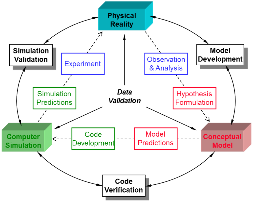
Figure 1.
The “New” scientific method [27].
It is not really possible to say conclusively that our CFD solutions have a known accuracy and reliability. We can only point to our verification and validation bench marks. Even when one has carefully considered equation verification and application validation, there are still issues concerning Error Propagation. Precision with computers does not equate to accuracy. Small errors in initial and boundary conditions can propagate into solutions [29].
One must also realize that validation is a learning process, and the process is never complete. Inherent uncertainties can exist in model physics, initial conditions, boundary conditions, and even turbulent randomness which can exist as a barrier to repeatability of both physical experiments and numerical comparisons.
2. Results and Discussion
2.1. CFD Guidelines Used in the United States
To a large extent, V&V practice in the United States builds upon the experience and recommendations of previous CFD modelers from different disciplines and different fluid mechanics communities. One can also classify advice into several subcategories:
- General Guidelines for Aerodynamic and Fluid Mechanic Codes,
- Guidelines for Physical Modeling that is also relevant for CFD,
- Guidelines for Structural Loading,
- Guidelines for Atmospheric Transport, Dispersion and Diffusion, and
- Guidelines for HVAC (Heating, Ventilation and Air Conditioning), Fire and Natural Ventilation.
The attached Appendix titled: Guidelines for V&V of CFD Commonly Used in the United States provides a list of appropriate papers and reports to be used in satisfying oneself that a proposed model represents reality.
2.2. CFD Guidelines for Nuclear Safety Evaluation Defined by the Atomic Energy Society of Japan (AESJ)
AESJ guidelines [30] were made to utilize CFD models for dispersion calculations for nuclear safety evaluation of radiation dose. In Japan, wind tunnel experiments have been used for nuclear safety evaluation for more than 40 years by Japanese electric power companies. Today, it is customary to utilize CFD models instead of wind tunnel experiments for a preliminary evaluation to confirm the effect of additional structures on gas dispersion.
An outline of the guidelines is summarized in Table 1 in the same format as the other guidelines introduced in this paper. It took two years to complete the guidelines by the JAES (Japan Atomic Energy Society) working group, and one year was consumed to establish a V&V scheme based on comparisons with experimental wind tunnel data. Criteria were integrated from the COST (European Cooperation on Science and Technology) 732 guidelines [31] and the AESJ wind tunnel guidelines [32]. A safety factor is defined to be modified with the final calculated results based on the uncertainty factor of calculated results suggested in the ASME (American Society of Mechanical Engineering) V&V guidelines [33].

Table 1.
Outline of the guidelines defined by Japan Atomic Energy Society.
The AESJ guidelines will be revised periodically every five years based on the established general rules of the AESJ guidelines.
2.3. Best Practice Guidelines Defined by COST Action ES1006 in EU
The COST Action ES1006 was established to pursue a substantial improvement in the implementation of local-scale emergency response tools. The main objective is to evaluate and improve the reliability of local-scale emergency response tools on the basis of a comprehensive, concerted and harmonized cross-national approach. The main focus is the evaluation of the atmospheric dispersion models when used in urban or industrial environments with complex building structures, and their integration in emergency response systems.
The COST ES1006 Action is structured in three Working Groups, whose main activity is hereafter briefly summarized.
Working Group 1—Threats, Models and Data Requirements: characterizes and categorizes existing models as well as typical release scenarios.
Working Group 2—Test, Evaluation and Further Development: defines open and blind test scenarios, tests and assesses different modelling approaches, and outlines scientific strategies for improving the implementation of corresponding tools.
Working Group 3—Applicability, Implementation and Practical Guidance: deals with the practical constraints in the use of local-scale emergency response models.
The Best Practice Guidelines (BPG) [35] are formulated as a concise and focused document that can be straightforwardly consulted by potential users. The most important aspects that guide the final recommendations are summarized above, while, for in-depth analysis, one is referred to the specific and detailed publications documents prepared in the frame of the COST ES1006 Action work. The outline of BPG [35] is summarized in Table 2.
Table 2.
Outline of the best practice guidelines defined by COST Action ES1006.
2.4. CFD Guidelines for Environmental Assessment Defined by the Japan Society for Atmospheric Environment (JSAE)
JSAE guidelines [36] were made to utilize CFD models for environmental impact assessment for relatively short distance dispersion in urban complex. The CFD model used for this purpose is named “Diffusion Model with Computational Fluid Dynamics” abbreviated as DiMCFD to distinguish it from other popular CFD models which are mainly used for the analysis of fluid dynamics. In Japan, Gaussian plume and puff models have been used for the environmental impact assessment in the atmosphere for long time; however, it is apparent that Gaussian models produce large errors for dispersion in urban complex in which there are many buildings and complicated emission sources. Wind tunnel experiments were previously employed for impact assessment in urban areas; however, now relatively few wind-tunnel studies are performed for this purpose because of the higher costs. It is planned to utilize DiMCFD models instead of wind tunnel experiments and to confirm whether the DiMCFD actually give better performance than Gaussian models in urban areas.
Outline of the guidelines is summarized in Table 3 in the same format as the other guidelines introduced in this paper. It took four years to complete the guidelines by the working group of the JSAE. Criteria were also integrated from the COST 732 guidelines [31] and AIJ’s (Architectural Institute of Japan) Guidebook for Practical Applications of CFD to Pedestrian Wind Environment around Buildings [37].
Table 3.
Outline of the guidelines defined by Japan Society for Atmospheric Environment.
2.5. Guidelines for Microscale Modeling Defined by VDI in Germany
In Germany, the Commission on Clean Air within VDI (Verein Deutcher Inginieure) and DIN (Deutsches Institut für Normung) ensures fitness-for-purpose of tools and methods in environmental meteorology through the preparation of technical guidelines. The guideline Prognostic micro-scale wind field models—Evaluation for flow around buildings and obstacles was published in 2005, and the draft review has been published in 2015 for public consultation [40]. The guidelines consider micro scale meteorology models that typically calculate wind, turbulence, temperature, humidity in the vicinity of buildings considering orography and Coriolis force effects. A typical use of this type of model is environmental impact assessment. For this, the results of models evaluated according to this guideline can be used to calculate tracer dispersion. However, a specific guideline for the evaluation of tracer dispersion does not currently exist.
These guidelines ensure fitness-for-purpose of obstacle resolving prognostic models through an evaluation procedure involving three distinct steps: general evaluation, scientific evaluation and validation. The general evaluation checks that the model is comprehensible in the sense that it is well documented and the evaluation is traceable. The scientific evaluation checks the set of equations solved and the physical and numerical properties of the model by requiring e.g., that all three wind components are calculated from prognostic equations and that orographic and obstacle structure is explicitly resolved. It assesses whether Coriolis force, temperature and possibly phase changes are considered depending on the application range. Finally, the model results are validated based on comparisons with results of the same model, with analytic solutions and with wind tunnel data. Here, the guidelines do not distinguish between verification and validation. The comparison metric in all cases is the hit rate q which is calculated as q = (Σni)/N, where ni = 1 if |Pi − Oi|/|Oi| ≤ D or |Pi − Oi| ≤ W, ni = 0, otherwise. Pi and Oi are co-located normalized model results and comparison data, respectively, and N is the number of measurement points. W (absolute allowed deviation) and D (relative allowed deviation) are defined for each test case and the model is required to reach a minimal hit rate for each comparison in order to fulfill the guidelines (see Table 4 below for values). This metric reflects the aim of the guideline to identify fitness-for-purpose rather than ranking models according to their performance. To test fundamental properties such as homogeneity of results over homogeneous terrain, symmetry of the results for symmetric obstacles and stationarity for stationary boundary conditions model results are compared with results of the same model. To ensure that the results are physically realistic, wind profiles for an empty domain are compared with an analytic solution. Finally, several test cases involve the comparison with reference data from wind tunnel measurements. The obstacle configurations include individual obstacles of different shapes (beam, cube, cuboid) as well as one case with a highly complex building configuration corresponding to that of a generic European urban center. The comparison data used in the guideline is based on the CEDVAL (Compilation of Experimental Data for Validation of Microscale Dispersion Models) database (EWTL (Environmental Wind Tunnel Laboratory), 2016) [37].
Table 4.
Outline of the guidelines defined by the Commission on Clean Air (KRdL (Kommission Reinhaltung der Luft)) and German Engineering Society (VDI).
Since their first publication in 2005, the guidelines have been applied to several microscale models [41,42,43,44]. The guidelines are revised when deemed necessary (e.g., when new relevant datasets become available), normally every five years. An update of the guidelines is currently in public consultation.
2.6. Guideline for CFD Modeling Defined by Architectural Institute of Japan
Computer facilities and computational fluid dynamics (CFD) software have significantly improved in recent years; therefore, using CFD to predict and assess the pedestrian wind environment around buildings has become practical at the building design stages. Consequently, guidelines that summarize the important aspects relevant to using the CFD technique for appropriately predicting the pedestrian wind environment are a necessity. In 2008, the Architectural Institute of Japan (AIJ) proposed practical guidelines for applying CFD to the pedestrian wind environment around buildings [45]. These guidelines were based on the results of benchmark tests, in which cross comparisons were conducted between the results of the CFD predictions, wind tunnel tests, and the field measurements of seven test cases. The aim of these seven test cases was to investigate the influence of numerous types of computational conditions for various flow fields [46,47,48]. Researchers worldwide have been referring to these guidelines, as is evident from the 335 citations in ScienceDirect up to 2015.
The abovementioned guidelines and the relevant investigations mainly targeted the problems pertaining to the strong wind around high-rise buildings. However, major environmental problems (urban heat island, thermal environment, air pollution, and particle dispersion, etc.) are often caused in weak wind regions, such as at the back of buildings and within street canyons. Generally, CFD predictions relevant to a weak wind flow region are more challenging than those for an area of strong wind flow. Therefore, although the previous guidelines are quite effective in the pollutant dispersion, the guidelines needed to be re-examined and extended in terms of their applicability to comprehensive environmental problems. Furthermore, while the abovementioned guidelines mainly focus on steady RANS (Reynolds-averaged Navier–Stokes equations) models, it is highly expected to establish appropriate practical guidelines for application of Large Eddy Simulation (LES). For this purpose, the benchmark tests are being re-conducted, using the new reliable experimental database provided by the AIJ group, as well as the previous guidelines. In the benchmark tests, a systematic approach is being taken, i.e., from a simple to a complicated case, and the influence of various computational conditions on the prediction results is being investigated methodically. Parts of the results of the benchmark tests have already been published in scientific literature [49,50,51,52,53,54]. In addition, the endeavor to extend the guidelines to include urban pollutant/thermal dispersion problems is continuing as noted in Table 5.
Table 5.
Outline of the extended AIJ (Architectural Institute of Japan) guidelines (ongoing).
3. Conclusions
The intent of this paper was the review of CFD guidelines used by different national professional bodies as currently proposed to guide the realistic prediction of dispersion and transport in the atmosphere, within and around buildings, terrain features and urban complexes. This paper is not a comprehensive review of CFD modeling techniques, nor is it intended to provide a final specification of best practices to be used by the modeling community. There are many similarities in the protocols currently employed as well as differences between individual guidelines. At some point in the future, it may be possible to arrive at a consensus for an international guideline for dispersion modeling, but, in the meantime, this paper summarizes existing methodologies. The paper provides a basis for discussion and improved guidance.
We discussed CFD guidelines introduced in this paper at the special meeting at Computational Wind Engineering 2014 in the University of Hamburg and obtained the following consensus.
- (1)
- CFD models are very useful tools, but they have many uncertainties.
- (2)
- V&V schemes are valuable tools to minimize these uncertainties.
- (3)
- A generally accepted CFD guideline is necessary for the operational use of CFD models.
Author Contributions
All authors contributed equally to the discussion. Robert Meroney contributed to the chapters of Section 1. Introduction and Section 2.1. CFD Guidelines Used in the United States. Ryohji Ohba contributed to the chapter of Section 2.2. CFD Guidelines for Nuclear Safety Evaluation Defined by the Atomic Energy Society of Japan (AESJ). Bernd Leitl contributed to the chapter of Section 2.3. Best Practice Guidelines Defined by COST Action ES1006 in EU. Hiroaki Kondo contributed to the chapter of Section 2.4. CFD Guidelines for Environmental Assessment Defined by the Japan Society for Atmospheric Environment (JSAE). David Grawe contributed information to the chapter of Section 2.5. Guidelines for Microscale Modeling Defined by VDI in Germany. Yoshihide Tominaga contributed to the chapter of Section 2.6. Guideline for CFD Modeling Defined by Architectural Institute of Japan.
Conflicts of Interest
The authors declare no conflict of interest.
Abbreviation
| AIJ | the Architectural Institute of Japan |
| ANOVA | Analysis of Variance |
| ASME | American Society of Mechanical Engineers |
| BPG | Best Practice Guidelines |
| CEDVAL | Compilation of Experimental Data for Validation of Microscale Dispersion Models |
| CFD | Computational Fluid Dynamics |
| COST | European Cooperation on Science and Technology |
| DiMCFD | Diffusion Model with Computational Fluid Dynamics |
| DIN | Deutsches Institut für Normung (German Institute for Standardization) |
| EWTL | Environmental Wind Tunnel Laboratory |
| HVAC | Heating, Ventilation and Air Conditioning |
| JAES | Japan Atomic Energy Society |
| JSAE | Japan Society for Atmospheric Environment |
| KRdL | Kommision Reinhaltung der Luft |
| V&V | Verification and Validation |
| VDI | Verein Deutscher Ingenieure (The Association of German Engineers) |
Appendix
Guideline for Verification and Validation of CFD Commonly Used in the United States
(Notes prepared by Robert N. Meroney, Colorado State University)
General Guidelines for Aerodynamic and Fluid Mechanic Codes:
- NPARC Alliance. NPARC Alliance CFD Verification and Validation. Available online: http://www.grc.nasa.gov/WWW/wind/valid/homepage.html (accessed on 8 January 2016).
- Glossary of Verification and Validation Terms. Available online: http://www.grc.nasa.gov/WWW/wind/valid/tutorial/glossary.html (accessed on 8 January 2016).
- Verification Validation Cases. Available online: http://www.grc.nasa.gov/WWW/wind/valid/archive.html (accessed on 8 January 2016).
- Tutorials. Available online: http://www.grc.nasa.gov/WWW/wind/valid/tutorial/tutorial.html (accessed on 8 January 2016).
- AIAA. Guide for the Verification and Validation of Computational Fluid Dynamics Simulations; American Institute of Aeronautics and Astronautics: Reston, VA, USA, 1998; p. 19.
- Also see Oberkampf, W.L.; Trucano, T.G. Validation Methodology in Computational Fluid Dynamics; AIAA: Denver, CO, USA, 19–22 June 2000; p. 27.
- Also see Oberkampf, W.L. Verification and validation in computational simulation. In Proceedings of the Transport Task Force Meeting, Salt Lake City, UT, USA, 29 April–2 May 2004; p. 42.
- ASME. Standard for Verification and Validation in Computational Fluid Dynamics and Heat Transfer; ASME: New York, NY, USA, 2009; p. 100.
- Also see Coleman, H.W. An Overview of ASME V&V 20: Standard for Verification and Validation in Computational Fluid Dynamics and Heat Transfer. Available online: http://maretec.ist.utl.pt/html_files/CFD_workshops/html_files_2008/papers/COLEMAN.pdf (accessed on 8 January 2016).
- ASME. Journal of Fluids Engineering Editorial Policy Statement on the Control of Numerical Accuracy . Available online: http://journaltool. asme.org/Templates/JFENumAccuracy.pdf (accessed on 8 January 2016).
- AGARD. A Selection of Experimental Test Cases for the Validation of CFD Codes; AGARD: Neuilly sur Seine, France, 1994; p. 162.
- http://ftp.rta.nato.int/public/PubFullText/AGARD/AR/AGARD-AR-303-VOLUME-1/AGARD-AR-303-VOLUME-1.pdf (accessed on 8 January 2016).
- http://ftp.rta.nato.int/public//PubFullText/AGARD/AR/AGARD-AR-303-VOLUME-2///AGARD-AR-303-VOLUME-2.pdf (accessed on 8 January 2016).
- Stern, F.; Wilson, R.V.; Coleman, H.W.; Paterson, E.G. Verification and Validation of CFD Simulations. Available online: http://www.simman2008.dk/PDF/iihr_407.pdf (accessed on 23 April 2016).
Guidelines for Physical Modeling (also relevant for CFD):
- Snyder, W.H. Guideline for Fluid Modeling of Atmospheric Diffusion; Environmental Protection Agency: Washington, DC, USA, 1981; p. 185.
- Meroney, R.N. Guideline for Fluid Modeling of Liquefied Natural Gas Cloud Dispersion; Gas Research Institute: Chicago, IL, USA, 1986; p. 262.
- Or see Meroney, R.N. Guidelines for Fluid Modeling of Dense Gas Cloud Dispersion. J. Hazard. Mater. 1988, 17, 23–46.
- ASME. Test Uncertainty; ASME PTC 19.1-2005; ASME, United States, 2005; p. 105.
Guidelines for Atmospheric Transport, Dispersion and Diffusion:
- Olesen, H.R. The Model Validation Kit–status and outlook. Int. J. Environ. Pollut. 2000, 14, pp. 65–76.
- Olesen, H.R. User’s Guide to the Model Validation Kit; National Environmental Research Institute, Ministry of the Environment: Copenhagen, Denmark, 2005; p. 72.
- Chang, J.C.; Hanna, S.R. Technical Descriptions and User’s Guide for the BOOT Statistical Model Evaluation Software Package, Version 2.0. Available online: http://www.harmo.org/kit/Download/BOOT_UG.pdf (accessed on 23 April 2016).
- Hangan, H. Experimental, numerical and analytical models for an atmospheric dispersion study. ASCE J. Aerosp. Eng. 1999, 12, 161–167.
- Meroney, R.N. Wind tunnel and numerical simulation of pollution dispersion: A Hybrid approach. In Proceedings of the Croucher Advanced Study Institute, Hong University of Science and Technology, Hong Kong, China, 6–10 December 2004.
- Huber, A.H.; Tang, W.; Flowe, A.; Bell, B.; Kuehlert, K.H.; Schwarz, W. Development and applications of CFD simulations in support of air quality studies involumeving buildings. In Proceedings of the 13th Joint Conference on the Applications of Air Pollution Meteorology with the Air Waste Management Association, Vancouver, BC, Canada, 23–27 August 2004.
Guidelines for HVAC, Fire and Natural Ventilation:
- Hostikka, S. State of the art of CFD fire models. In Proceedings of the 10th International Fire Protection Symposium on “Methods of Fire Safety Engineering”, Hanover, Germany, 6–7 June 2005; p. 15.
- Janssesn, M.L. An Introduction to Mathematical Fire Modeling; CRC Press: Boca Raton, FL, USA, 2000; p. 277.
- Blackmore, B.; Xu, W. Guidelines for Accurate Clean Room CFD Modeling All Relevant Physics and Heat Sources Must Be Considered; Clean Rooms Newsletter. Available online: http://electroiq.com/blog/2006/05/guidelines-for-accurate-cleanroom-cfd-modeling/ (accessed on 23 April 2016)
- McGrattan, K. Computational Fluid Dynamics and Fire Modeling; NIST, Fire Program: Washington, DC, USA, 2001.
- Chen, Q.; Srebic, J. A procedure for Verification, Validation, and Reporting of Indoor Environment CFD Analyses. Available online: https://engineering.purdue.edu/~yanchen/paper/2002-6.pdf (accessed on 8 January 2016).
- Baker, A.J.; Kelso, R.M. On validation of computational fluid dynamics procedures for room air motion predictions. ASHRAE Trans. 1990, 96, 760–774.
- Baker, A.J.; Kelso, R.M.; Gordon, E.B.; Roy, S.R.; Schaub, E.G. Computational fluid dynamics: A two-edged sword. ASHRAE J. 1997, 39, 51–58.
References
- CFD Online. Application Area. Available online: http://www.cfd-online.com/Wiki/Application_areas (accessed on 23 April 2016).
- Lateb, M.; Meroney, R.N. On the use of numerical modelling for near-field pollutant dispersion in urban environments—A review. Environ. Pollut. 2016, 208, 271–283. [Google Scholar] [CrossRef] [PubMed]
- Meroney, R.N.; Derickson, R. Virtual reality in wind engineering: The windy world within the computer. J. Wind Eng. 2014, 11, 11–26. [Google Scholar]
- Meroney, R.N. Ten questions concerning hybrid computational/physical model simulation of wind flow in the built environment. Build. Environ. 2016, 96, 12–21. [Google Scholar] [CrossRef]
- Murakami, S. Current status and future trends in computational wind engineering. J. Wind Eng. Ind. Aerodyn. 1997, 67, 3–34. [Google Scholar] [CrossRef]
- Stathopoulos, T. Computational wind engineering: Is it mature for civil engineering applications? J. Aerosp. Eng. 1999, 12, 111–112. [Google Scholar] [CrossRef]
- Spalding, B. Computational fluid dynamics on the internet. In Proceedings of EUROTEX Workshop on Internet-and Web-Based Computing, Dallas, TX, USA, 13–15 April 1999.
- Castro, I.P.; Graham, J.M.R. Numerical wind engineering: The Way Ahead? Proc. Inst. Civil Eng. Struct. Build. 1999, 134, 275–277. [Google Scholar] [CrossRef]
- Castro, I.P. CFD for External Aerodynamics in the built environment. QNET-CFD Netw. Newslett. 2003, 2, 4–7. [Google Scholar]
- Shin, S.H.; Meroney, R.N. Surface pattern comparability of wind-tunnel simulations of the Thorney Island dense gas dispersion trials. In Air Pollution Modeling and Its Application; van Dop, H., VII, Ed.; Plenum Press: New York, NY, USA, 1989; pp. 77–88. [Google Scholar]
- Shin, S.H.; Meroney, R.N.; Williams, T. Wind tunnel validation for vapor dispersion from vapor detention system. In Proceedings of the International Conference and Workshop on Modeling and Mitigating the Consequences of Accidental Releases of Hazardous Materials, New Orleans, LA, USA, 21–24 May 1991.
- National Aeronautics and Space Administration. NPARC Alliance CFD Verification and Validation. Available online: http://www.grc.nasa.gov/WWW/wind/valid/homepage.html (accessed on 8 January 2016).
- ERCOFTAC. Available online: http://www.ercoftac.org/special_interest_groups /5_environmental_fluid_mechanics/ (accessed on 23 April 2016).
- AIAA. Guide for the Verification and Validation of Computational Fluid Dynamics Simulations; American Institute of Aeronautics and Astronautics: Reston, VA, USA, 1998; p. 19. [Google Scholar]
- Meroney, R.N. Fire whirls and building aerodynamics. In Proceedings of the 11th International Conference on Wind Engineering, Texas Tech University, Lubbock, TX, USA, 2–5 June 2003; p. 3.
- Meroney, R.N. Protocol for CFD prediction of cooling-tower drift in an urban environment. J. Wind Eng. Ind. Aerodyn. 2008, 96, 1789–1804. [Google Scholar] [CrossRef]
- Ohba, R.; Ukeguchi, N.; Okamoto, H. The numerical analysis of the diffusion around structures. In Proceedings of International Clean Air Conference, Rotorua, New Zealand, 17–21 February 1975; p. 10.
- Meroney, R.N. CFD Prediction of airflow in buildings for natural ventilation. In Proceedings of the 11th Americas Conference on Wind Engineering, San Juan, Puerto Rico, 22–26 June 2009; p. 11.
- Meroney, R.N. CFD Prediction of dense gas clouds spreading in a mock urban environment. In Proceedings of the 5th International Symposium on Computational Wind Engineering, Chapel Hill, NC, USA, 23–27 May 2010; p. 8.
- Meroney, R.N.; Neff, D.E. Wind effects on roof-mounted solar photovoltaic arrays: CFD and wind-tunnel evaluation. In Proceedings of the 5th International Symposium on Computational Wind Engineering, Chapel Hill, NC, USA, 23–27 May 2010; p. 8.
- Meroney, R.N.; Letchford, C.W.; Sarkar, P.P. Comparison of numerical and wind tunnel simulation of wind loads on smooth and rough domes immersed in a boundary layer. In Proceedings of the 3rd International Symposium on Computational Wind Engineering, Birmingham, UK, 4–7 September 2000; p. 12.
- Meroney, R.N.; Banks, D.; Chang, C.H. CFD simulation of the progress of fires in building atria, session on computational evaluation of wind effects on buildings. In Proceedings of the ASCE 2002 Structures Congress, Denver, CO, USA, 4–6 April 2002; p. 2.
- Meroney, R.N.; Neff, D.E.; Chang, C.H. Diagnosis of a sick building by the wind doctors. In Proceedings of the Second International Symposium on Advances in Wind and Structures, Busan, Korea, 21–23 August 2002; pp. 43–52.
- Meroney, R.N.; Neff, D.E.; Chang, C.H.; Predoto, R. Computational fluid dynamics and physical model comparisons of wind loads and pedestrian comfort around a high rise building, session on computational evaluation of wind effects on buildings. In Proceedings of the ASCE 2002 Structures Congress, Denver, CO, USA, 4–6 April 2002; p. 2.
- Banks, D.; Meroney, R.N.; Petersen, R.L.; Carter, J.J. Evaluation of FLUENT for predicting concentrations on buildings. In Proceedings of the Annual Meeting of the AWMA (Air and Waste Management Association), San Diego, CA, USA, 14–18 June 2003; p. 11.
- Meroney, R.N. Wind Tunnel and Numerical Simulation of Pollution Dispersion: A Hybrid Approach. Available online: http://www.engr.colostate.edu/~meroney/projects/ASI%20Crocher%20Paper%20Final.pdf (accessed on 5 May 2016).
- Rahaim, C.P.; Oberkampf, W.; Cosner, R.R.; Dominik, D.F. AIAA committee on standards for computational fluid dynamics–Current status and plans for international verification database. In Proceedings of the AIAA Aerospace Sciences Meeting, Reno, NV, USA, 6–9 January 2003; p. 21.
- Knepell, P.L.; Arangno, D.C. Simulation Validation: A Confidence Assessment Methodology; Wiley-IEEE Computer Society Press: Los Alamitos, CA, USA, 1993; p. 168. [Google Scholar]
- Beychok, M.R. Error Propagation in Air Dispersion Modeling, extracted from Fundamentals of Stack Gas Dispersion, Irvine, CA, USA. 2005. Available online: https://en.wikipedia.org/wiki/Fundamentals_of_Stack_Gas_Dispersion (accessed on 8 January 2016).
- Atomic Energy Society of Japan (AESJ). Code for Numerical Model to Calculate the Effective Source Height for Nuclear Power Facilities Safety Analysis; Atomic Energy Society of Japan: Tokyo, Japan, 2011. [Google Scholar]
- Britter, R.; Schatzmann, M. Model Evaluation Guidance and Protocol Document. Available online: http://www.cost.eu/media/publications/07-64-Model-Evaluation-Guidance-and-Protocol-Document (accessed on 8 January 2016).
- Atomic Energy Society of Japan (AESJ). Code for Wind Tunnel Experiments to Calculate the Effective Height of Emitting Source for Nuclear Power Facilities Safety Analysis; Atomic Energy Society of Japan: Tokyo, Japan, 2009. [Google Scholar]
- ASME. Standard for Verification and Validation in Computational Fluid Dynamics and Heat Transfer. Available online: https://www.asme.org/shop (accessed on 23 April 2016).
- University of Hamburg. Environmental Wind Tunnel Laboratory (EWTL) Compilation of Experimental Data for Validation of Microsclae Dispersion Models (CEDVAL, CEDVAL-LES). Available online: https://www.mi.uni-hamburg.de/ewtl (accessed on 8 January 2016).
- The Editorial Board of COST Action ES1006. COST ES1006 Best Practice Guideline. 2015. Available online: http://www.elizas.eu/index.php/documents-of-the-action (accessed on 7 January 2016).
- Japan Society for Atmospheric Environment. Guideline on Atmospheric Environmental Impact Assessment Using CFD Models. 2013. Available online: http://www.jsae-net.org/public/DiMCFD_20131021.pdf (accessed on 8 January 2016).
- Architecture Institute of Japan. Guidebook for Practical Applications of CFD to Pedestrian Wind Environment around Buildings. 2009. Available online: http://www.aij.or.jp/jpn/publish/cfdguide/index_e.htm (accessed on 8 January 2016).
- National Institute of Advanced Industrial Science and Technology. Summary of Wind Tunnel Experiment for Validation of the DiMCFD Model. 2013. Available online: https://unit.aist.go.jp/emtech-ri/ci/research_result/db/01/db_01.html (accessed on 8 January 2016).
- EPA. Guideline on the Development, Evaluation, and Application of Environmental Models. EPA/100/K-09/003; 2009. Available online: https://www.epa.gov/modeling/guidance-document-development-evaluation-and-application-environmental-models (accessed on 23 April 2016). [Google Scholar]
- The Association of German Engineers (VDI). Environmental Meteorology. Prognostic Micro-Scale Wind Field Models. Evaluation for Flow around Buildings and Obstacles. VDI 3783 Part 9. 2015. Available online: http://www.vdi.eu/nc/guidelines/vdi_3783_blatt_9-umweltmeteorologie_prognostische_mikroskalige_windfeldmodelle_evaluierung_fr_gebude_und/ (accessed on 11 February 2016).
- Oettl, D. Quality assurance of the prognostic, microscale wind-field model GRAL 14.8 using wind-tunnel data provided by the German VDI guideline 3783-9. J. Wind Eng. Ind. Aerodyn. 2015, 142, 104–110. [Google Scholar] [CrossRef]
- Grawe, D.; Schlünzen, K.H.; Pascheke, F. Comparison of results of an obstacle resolving microscale model with wind tunnel data. Atmosp. Environ. 2013, 73, 495–509. [Google Scholar] [CrossRef]
- Franke, J.; Sturm, M.; Kalmbach, C. Validation of OpenFOAM 1.6.x with the German VDI guideline for obstacle resolving micro-scale models. J. Wind Eng. Ind. Aerodyn. 2012, 104, 350–359. [Google Scholar]
- Eichhorn, J.; Kniffka, A. The numerical flow model MISKAM: State of development and evaluation of the basic version. Meteorol. Z. 2010, 19, 81–90. [Google Scholar] [CrossRef]
- Tominaga, Y.; Mochida, A.; Yoshie, R.; Kataoka, H.; Nozu, T.; Yoshikawa, M.; Shirasawa, T. AIJ guidelines for practical applications of CFD to pedestrian wind environment around buildings. J. Wind Eng. Ind. Aerodyn. 2008, 96, 1749–1761. [Google Scholar] [CrossRef]
- Mochida, A.; Tominaga, Y.; Murakami, S.; Yoshie, R.; Ishihara, T.; Ooka, R. Comparison of various k-ε model and DSM applied to flow around a high-rise building-report on AIJ cooperative project for CFD prediction of wind environment. Wind Struct. 2002, 5, 227–244. [Google Scholar] [CrossRef]
- Tominaga, Y.; Mochida, A.; Shirasawa, T.; Yoshie, R.; Kataoka, H.; Harimoto, K.; Nozu, T. Cross comparisons of CFD results of wind environment at pedestrian level around a high-rise building and within a building complex. J. Asian Archit. Build. Eng. 2004, 3, 63–70. [Google Scholar] [CrossRef]
- Yoshie, R.; Mochida, A.; Tominaga, Y.; Kataoka, H.; Harimoto, K.; Nozu, T.; Shirasawa, T. Cooperative project for CFD prediction of pedestrian wind environment in the Architectural Institute of Japan. J. Wind Eng. Ind. Aerodyn. 2007, 95, 1551–1578. [Google Scholar] [CrossRef]
- Yoshie, R.; Guoyi, J.; Shirasawa, T.; Chung, J. CFD simulations of gas dispersion around high-rise building in non-isothermal boundary layer. J. Wind Eng. Ind. Aerodyn. 2011, 99, 279–288. [Google Scholar] [CrossRef]
- Tominaga, Y.; Iizuka, S.; Imano, M.; Kataoka, H.; Mochida, A.; Nozu, T.; Ono, Y.; Shirasawa, T.; Tsuchiya, N.; Yoshie, R. Cross comparisons of cfd results of wind and dispersion fields for MUST experiment: Evaluation exercises by AIJ. J. Asian Archit. Build. Eng. 2013, 12, 117–124. [Google Scholar] [CrossRef]
- Yoshie, R.; Okaze, T.; Tominaga, Y.; Shirasawa, T.; Mochida, A. AIJ cooperative project for practical application of CFD to pollutant/thermal dispersion in urban areas (Part 1) Introduction of benchmark tests. In Proceedings of the 6th International Symposium on Computational Wind Engineering (CWE2014), Hamburg, Germany, 8–12 June 2014.
- Shirasawa, T.; Yoshie, R.; Tominaga, Y.; Okaze, T.; Jiang, G.; Imano, M.; Kishida, T.; Mochida, A. AIJ cooperative project for practical application of CFD to pollutant/thermal dispersion in urban areas (Part 2) Pollutant/thermal dispersion behind single building case. In Proceedings of the 6th International Symposium on Computational Wind Engineering (CWE2014), Hamburg, Germany, 8–12 June 2014.
- Yoshie, R.; Okaze, T.; Jiang, G.; Tominaga, Y.; Shirasawa, T.; Imano, M.; Mochida, A. AIJ cooperative project for practical application of CFD to pollutant/thermal dispersion in urban areas (Part 3) Pollutant/thermal dispersion in simple street canyon models. In Proceedings of the 6th International Symposium on Computational Wind Engineering (CWE2014), Hamburg, Germany, 8–12 June 2014.
- Tominaga, Y.; Yoshie, R.; Okaze, T.; Shirasawa, T.; Mochida, A. AIJ cooperative project for practical application of CFD to pollutant/thermal dispersion in urban areas (Part 4): Flow and dispersion fields around building complex in actual urban area. In Proceedings of the 6th International Symposium on Computational Wind Engineering (CWE2014), Hamburg, Germany, 8–12 June 2014.

© 2016 by the authors; licensee MDPI, Basel, Switzerland. This article is an open access article distributed under the terms and conditions of the Creative Commons Attribution license ( http://creativecommons.org/licenses/by/4.0/).